WO2015159954A1 - 排気浄化システム - Google Patents
排気浄化システム Download PDFInfo
- Publication number
- WO2015159954A1 WO2015159954A1 PCT/JP2015/061732 JP2015061732W WO2015159954A1 WO 2015159954 A1 WO2015159954 A1 WO 2015159954A1 JP 2015061732 W JP2015061732 W JP 2015061732W WO 2015159954 A1 WO2015159954 A1 WO 2015159954A1
- Authority
- WO
- WIPO (PCT)
- Prior art keywords
- temperature
- exhaust
- increase rate
- exhaust gas
- urea water
- Prior art date
- Legal status (The legal status is an assumption and is not a legal conclusion. Google has not performed a legal analysis and makes no representation as to the accuracy of the status listed.)
- Ceased
Links
Images


Classifications
-
- F—MECHANICAL ENGINEERING; LIGHTING; HEATING; WEAPONS; BLASTING
- F01—MACHINES OR ENGINES IN GENERAL; ENGINE PLANTS IN GENERAL; STEAM ENGINES
- F01N—GAS-FLOW SILENCERS OR EXHAUST APPARATUS FOR MACHINES OR ENGINES IN GENERAL; GAS-FLOW SILENCERS OR EXHAUST APPARATUS FOR INTERNAL-COMBUSTION ENGINES
- F01N3/00—Exhaust or silencing apparatus having means for purifying, rendering innocuous, or otherwise treating exhaust
- F01N3/08—Exhaust or silencing apparatus having means for purifying, rendering innocuous, or otherwise treating exhaust for rendering innocuous
- F01N3/10—Exhaust or silencing apparatus having means for purifying, rendering innocuous, or otherwise treating exhaust for rendering innocuous by thermal or catalytic conversion of noxious components of exhaust
- F01N3/18—Exhaust or silencing apparatus having means for purifying, rendering innocuous, or otherwise treating exhaust for rendering innocuous by thermal or catalytic conversion of noxious components of exhaust characterised by methods of operation; Control
- F01N3/20—Exhaust or silencing apparatus having means for purifying, rendering innocuous, or otherwise treating exhaust for rendering innocuous by thermal or catalytic conversion of noxious components of exhaust characterised by methods of operation; Control specially adapted for catalytic conversion
- F01N3/206—Adding periodically or continuously substances to exhaust gases for promoting purification, e.g. catalytic material in liquid form, NOx reducing agents
- F01N3/208—Control of selective catalytic reduction [SCR], e.g. by adjusting the dosing of reducing agent
-
- B—PERFORMING OPERATIONS; TRANSPORTING
- B01—PHYSICAL OR CHEMICAL PROCESSES OR APPARATUS IN GENERAL
- B01D—SEPARATION
- B01D53/00—Separation of gases or vapours; Recovering vapours of volatile solvents from gases; Chemical or biological purification of waste gases, e.g. engine exhaust gases, smoke, fumes, flue gases, aerosols
- B01D53/34—Chemical or biological purification of waste gases
- B01D53/92—Chemical or biological purification of waste gases of engine exhaust gases
- B01D53/94—Chemical or biological purification of waste gases of engine exhaust gases by catalytic processes
- B01D53/9404—Removing only nitrogen compounds
- B01D53/9409—Nitrogen oxides
- B01D53/9413—Processes characterised by a specific catalyst
- B01D53/9418—Processes characterised by a specific catalyst for removing nitrogen oxides by selective catalytic reduction [SCR] using a reducing agent in a lean exhaust gas
-
- B—PERFORMING OPERATIONS; TRANSPORTING
- B01—PHYSICAL OR CHEMICAL PROCESSES OR APPARATUS IN GENERAL
- B01D—SEPARATION
- B01D53/00—Separation of gases or vapours; Recovering vapours of volatile solvents from gases; Chemical or biological purification of waste gases, e.g. engine exhaust gases, smoke, fumes, flue gases, aerosols
- B01D53/34—Chemical or biological purification of waste gases
- B01D53/92—Chemical or biological purification of waste gases of engine exhaust gases
- B01D53/94—Chemical or biological purification of waste gases of engine exhaust gases by catalytic processes
- B01D53/9404—Removing only nitrogen compounds
- B01D53/9409—Nitrogen oxides
- B01D53/9431—Processes characterised by a specific device
-
- B—PERFORMING OPERATIONS; TRANSPORTING
- B01—PHYSICAL OR CHEMICAL PROCESSES OR APPARATUS IN GENERAL
- B01D—SEPARATION
- B01D53/00—Separation of gases or vapours; Recovering vapours of volatile solvents from gases; Chemical or biological purification of waste gases, e.g. engine exhaust gases, smoke, fumes, flue gases, aerosols
- B01D53/34—Chemical or biological purification of waste gases
- B01D53/92—Chemical or biological purification of waste gases of engine exhaust gases
- B01D53/94—Chemical or biological purification of waste gases of engine exhaust gases by catalytic processes
- B01D53/9459—Removing one or more of nitrogen oxides, carbon monoxide, or hydrocarbons by multiple successive catalytic functions; systems with more than one different function, e.g. zone coated catalysts
- B01D53/9477—Removing one or more of nitrogen oxides, carbon monoxide, or hydrocarbons by multiple successive catalytic functions; systems with more than one different function, e.g. zone coated catalysts with catalysts positioned on separate bricks, e.g. exhaust systems
-
- B—PERFORMING OPERATIONS; TRANSPORTING
- B01—PHYSICAL OR CHEMICAL PROCESSES OR APPARATUS IN GENERAL
- B01D—SEPARATION
- B01D53/00—Separation of gases or vapours; Recovering vapours of volatile solvents from gases; Chemical or biological purification of waste gases, e.g. engine exhaust gases, smoke, fumes, flue gases, aerosols
- B01D53/34—Chemical or biological purification of waste gases
- B01D53/92—Chemical or biological purification of waste gases of engine exhaust gases
- B01D53/94—Chemical or biological purification of waste gases of engine exhaust gases by catalytic processes
- B01D53/9495—Controlling the catalytic process
-
- F—MECHANICAL ENGINEERING; LIGHTING; HEATING; WEAPONS; BLASTING
- F01—MACHINES OR ENGINES IN GENERAL; ENGINE PLANTS IN GENERAL; STEAM ENGINES
- F01N—GAS-FLOW SILENCERS OR EXHAUST APPARATUS FOR MACHINES OR ENGINES IN GENERAL; GAS-FLOW SILENCERS OR EXHAUST APPARATUS FOR INTERNAL-COMBUSTION ENGINES
- F01N11/00—Monitoring or diagnostic devices for exhaust-gas treatment apparatus
- F01N11/002—Monitoring or diagnostic devices for exhaust-gas treatment apparatus the diagnostic devices measuring or estimating temperature or pressure in, or downstream of the exhaust apparatus
-
- F—MECHANICAL ENGINEERING; LIGHTING; HEATING; WEAPONS; BLASTING
- F01—MACHINES OR ENGINES IN GENERAL; ENGINE PLANTS IN GENERAL; STEAM ENGINES
- F01N—GAS-FLOW SILENCERS OR EXHAUST APPARATUS FOR MACHINES OR ENGINES IN GENERAL; GAS-FLOW SILENCERS OR EXHAUST APPARATUS FOR INTERNAL-COMBUSTION ENGINES
- F01N11/00—Monitoring or diagnostic devices for exhaust-gas treatment apparatus
- F01N11/007—Monitoring or diagnostic devices for exhaust-gas treatment apparatus the diagnostic devices measuring oxygen or air concentration downstream of the exhaust apparatus
-
- F—MECHANICAL ENGINEERING; LIGHTING; HEATING; WEAPONS; BLASTING
- F01—MACHINES OR ENGINES IN GENERAL; ENGINE PLANTS IN GENERAL; STEAM ENGINES
- F01N—GAS-FLOW SILENCERS OR EXHAUST APPARATUS FOR MACHINES OR ENGINES IN GENERAL; GAS-FLOW SILENCERS OR EXHAUST APPARATUS FOR INTERNAL-COMBUSTION ENGINES
- F01N3/00—Exhaust or silencing apparatus having means for purifying, rendering innocuous, or otherwise treating exhaust
- F01N3/08—Exhaust or silencing apparatus having means for purifying, rendering innocuous, or otherwise treating exhaust for rendering innocuous
- F01N3/10—Exhaust or silencing apparatus having means for purifying, rendering innocuous, or otherwise treating exhaust for rendering innocuous by thermal or catalytic conversion of noxious components of exhaust
- F01N3/18—Exhaust or silencing apparatus having means for purifying, rendering innocuous, or otherwise treating exhaust for rendering innocuous by thermal or catalytic conversion of noxious components of exhaust characterised by methods of operation; Control
- F01N3/20—Exhaust or silencing apparatus having means for purifying, rendering innocuous, or otherwise treating exhaust for rendering innocuous by thermal or catalytic conversion of noxious components of exhaust characterised by methods of operation; Control specially adapted for catalytic conversion
-
- B—PERFORMING OPERATIONS; TRANSPORTING
- B01—PHYSICAL OR CHEMICAL PROCESSES OR APPARATUS IN GENERAL
- B01D—SEPARATION
- B01D2251/00—Reactants
- B01D2251/20—Reductants
- B01D2251/206—Ammonium compounds
- B01D2251/2067—Urea
-
- B—PERFORMING OPERATIONS; TRANSPORTING
- B01—PHYSICAL OR CHEMICAL PROCESSES OR APPARATUS IN GENERAL
- B01D—SEPARATION
- B01D2258/00—Sources of waste gases
- B01D2258/01—Engine exhaust gases
- B01D2258/012—Diesel engines and lean burn gasoline engines
-
- F—MECHANICAL ENGINEERING; LIGHTING; HEATING; WEAPONS; BLASTING
- F01—MACHINES OR ENGINES IN GENERAL; ENGINE PLANTS IN GENERAL; STEAM ENGINES
- F01N—GAS-FLOW SILENCERS OR EXHAUST APPARATUS FOR MACHINES OR ENGINES IN GENERAL; GAS-FLOW SILENCERS OR EXHAUST APPARATUS FOR INTERNAL-COMBUSTION ENGINES
- F01N2550/00—Monitoring or diagnosing the deterioration of exhaust systems
- F01N2550/02—Catalytic activity of catalytic converters
-
- F—MECHANICAL ENGINEERING; LIGHTING; HEATING; WEAPONS; BLASTING
- F01—MACHINES OR ENGINES IN GENERAL; ENGINE PLANTS IN GENERAL; STEAM ENGINES
- F01N—GAS-FLOW SILENCERS OR EXHAUST APPARATUS FOR MACHINES OR ENGINES IN GENERAL; GAS-FLOW SILENCERS OR EXHAUST APPARATUS FOR INTERNAL-COMBUSTION ENGINES
- F01N2550/00—Monitoring or diagnosing the deterioration of exhaust systems
- F01N2550/05—Systems for adding substances into exhaust
-
- F—MECHANICAL ENGINEERING; LIGHTING; HEATING; WEAPONS; BLASTING
- F01—MACHINES OR ENGINES IN GENERAL; ENGINE PLANTS IN GENERAL; STEAM ENGINES
- F01N—GAS-FLOW SILENCERS OR EXHAUST APPARATUS FOR MACHINES OR ENGINES IN GENERAL; GAS-FLOW SILENCERS OR EXHAUST APPARATUS FOR INTERNAL-COMBUSTION ENGINES
- F01N2560/00—Exhaust systems with means for detecting or measuring exhaust gas components or characteristics
- F01N2560/02—Exhaust systems with means for detecting or measuring exhaust gas components or characteristics the means being an exhaust gas sensor
- F01N2560/026—Exhaust systems with means for detecting or measuring exhaust gas components or characteristics the means being an exhaust gas sensor for measuring or detecting NOx
-
- F—MECHANICAL ENGINEERING; LIGHTING; HEATING; WEAPONS; BLASTING
- F01—MACHINES OR ENGINES IN GENERAL; ENGINE PLANTS IN GENERAL; STEAM ENGINES
- F01N—GAS-FLOW SILENCERS OR EXHAUST APPARATUS FOR MACHINES OR ENGINES IN GENERAL; GAS-FLOW SILENCERS OR EXHAUST APPARATUS FOR INTERNAL-COMBUSTION ENGINES
- F01N2560/00—Exhaust systems with means for detecting or measuring exhaust gas components or characteristics
- F01N2560/06—Exhaust systems with means for detecting or measuring exhaust gas components or characteristics the means being a temperature sensor
-
- F—MECHANICAL ENGINEERING; LIGHTING; HEATING; WEAPONS; BLASTING
- F01—MACHINES OR ENGINES IN GENERAL; ENGINE PLANTS IN GENERAL; STEAM ENGINES
- F01N—GAS-FLOW SILENCERS OR EXHAUST APPARATUS FOR MACHINES OR ENGINES IN GENERAL; GAS-FLOW SILENCERS OR EXHAUST APPARATUS FOR INTERNAL-COMBUSTION ENGINES
- F01N2610/00—Adding substances to exhaust gases
- F01N2610/02—Adding substances to exhaust gases the substance being ammonia or urea
-
- F—MECHANICAL ENGINEERING; LIGHTING; HEATING; WEAPONS; BLASTING
- F01—MACHINES OR ENGINES IN GENERAL; ENGINE PLANTS IN GENERAL; STEAM ENGINES
- F01N—GAS-FLOW SILENCERS OR EXHAUST APPARATUS FOR MACHINES OR ENGINES IN GENERAL; GAS-FLOW SILENCERS OR EXHAUST APPARATUS FOR INTERNAL-COMBUSTION ENGINES
- F01N2900/00—Details of electrical control or of the monitoring of the exhaust gas treating apparatus
- F01N2900/06—Parameters used for exhaust control or diagnosing
- F01N2900/14—Parameters used for exhaust control or diagnosing said parameters being related to the exhaust gas
- F01N2900/1402—Exhaust gas composition
-
- F—MECHANICAL ENGINEERING; LIGHTING; HEATING; WEAPONS; BLASTING
- F01—MACHINES OR ENGINES IN GENERAL; ENGINE PLANTS IN GENERAL; STEAM ENGINES
- F01N—GAS-FLOW SILENCERS OR EXHAUST APPARATUS FOR MACHINES OR ENGINES IN GENERAL; GAS-FLOW SILENCERS OR EXHAUST APPARATUS FOR INTERNAL-COMBUSTION ENGINES
- F01N2900/00—Details of electrical control or of the monitoring of the exhaust gas treating apparatus
- F01N2900/06—Parameters used for exhaust control or diagnosing
- F01N2900/14—Parameters used for exhaust control or diagnosing said parameters being related to the exhaust gas
- F01N2900/1404—Exhaust gas temperature
-
- F—MECHANICAL ENGINEERING; LIGHTING; HEATING; WEAPONS; BLASTING
- F01—MACHINES OR ENGINES IN GENERAL; ENGINE PLANTS IN GENERAL; STEAM ENGINES
- F01N—GAS-FLOW SILENCERS OR EXHAUST APPARATUS FOR MACHINES OR ENGINES IN GENERAL; GAS-FLOW SILENCERS OR EXHAUST APPARATUS FOR INTERNAL-COMBUSTION ENGINES
- F01N2900/00—Details of electrical control or of the monitoring of the exhaust gas treating apparatus
- F01N2900/06—Parameters used for exhaust control or diagnosing
- F01N2900/16—Parameters used for exhaust control or diagnosing said parameters being related to the exhaust apparatus, e.g. particulate filter or catalyst
- F01N2900/1602—Temperature of exhaust gas apparatus
-
- F—MECHANICAL ENGINEERING; LIGHTING; HEATING; WEAPONS; BLASTING
- F01—MACHINES OR ENGINES IN GENERAL; ENGINE PLANTS IN GENERAL; STEAM ENGINES
- F01N—GAS-FLOW SILENCERS OR EXHAUST APPARATUS FOR MACHINES OR ENGINES IN GENERAL; GAS-FLOW SILENCERS OR EXHAUST APPARATUS FOR INTERNAL-COMBUSTION ENGINES
- F01N2900/00—Details of electrical control or of the monitoring of the exhaust gas treating apparatus
- F01N2900/06—Parameters used for exhaust control or diagnosing
- F01N2900/18—Parameters used for exhaust control or diagnosing said parameters being related to the system for adding a substance into the exhaust
- F01N2900/1806—Properties of reducing agent or dosing system
- F01N2900/1812—Flow rate
-
- Y—GENERAL TAGGING OF NEW TECHNOLOGICAL DEVELOPMENTS; GENERAL TAGGING OF CROSS-SECTIONAL TECHNOLOGIES SPANNING OVER SEVERAL SECTIONS OF THE IPC; TECHNICAL SUBJECTS COVERED BY FORMER USPC CROSS-REFERENCE ART COLLECTIONS [XRACs] AND DIGESTS
- Y02—TECHNOLOGIES OR APPLICATIONS FOR MITIGATION OR ADAPTATION AGAINST CLIMATE CHANGE
- Y02C—CAPTURE, STORAGE, SEQUESTRATION OR DISPOSAL OF GREENHOUSE GASES [GHG]
- Y02C20/00—Capture or disposal of greenhouse gases
- Y02C20/10—Capture or disposal of greenhouse gases of nitrous oxide (N2O)
-
- Y—GENERAL TAGGING OF NEW TECHNOLOGICAL DEVELOPMENTS; GENERAL TAGGING OF CROSS-SECTIONAL TECHNOLOGIES SPANNING OVER SEVERAL SECTIONS OF THE IPC; TECHNICAL SUBJECTS COVERED BY FORMER USPC CROSS-REFERENCE ART COLLECTIONS [XRACs] AND DIGESTS
- Y02—TECHNOLOGIES OR APPLICATIONS FOR MITIGATION OR ADAPTATION AGAINST CLIMATE CHANGE
- Y02T—CLIMATE CHANGE MITIGATION TECHNOLOGIES RELATED TO TRANSPORTATION
- Y02T10/00—Road transport of goods or passengers
- Y02T10/10—Internal combustion engine [ICE] based vehicles
- Y02T10/12—Improving ICE efficiencies
-
- Y—GENERAL TAGGING OF NEW TECHNOLOGICAL DEVELOPMENTS; GENERAL TAGGING OF CROSS-SECTIONAL TECHNOLOGIES SPANNING OVER SEVERAL SECTIONS OF THE IPC; TECHNICAL SUBJECTS COVERED BY FORMER USPC CROSS-REFERENCE ART COLLECTIONS [XRACs] AND DIGESTS
- Y02—TECHNOLOGIES OR APPLICATIONS FOR MITIGATION OR ADAPTATION AGAINST CLIMATE CHANGE
- Y02T—CLIMATE CHANGE MITIGATION TECHNOLOGIES RELATED TO TRANSPORTATION
- Y02T10/00—Road transport of goods or passengers
- Y02T10/10—Internal combustion engine [ICE] based vehicles
- Y02T10/40—Engine management systems
Definitions
- the present invention relates to an exhaust gas purification system, and more particularly to an exhaust gas purification system including a selective reduction catalyst (hereinafter referred to as SCR) for reducing and purifying NOx in exhaust gas.
- SCR selective reduction catalyst
- an exhaust gas purification system equipped with an SCR that selectively reduces and purifies NOx in exhaust gas using ammonia (hereinafter referred to as NH3) generated by hydrolysis from urea water as a reducing agent.
- NH3 ammonia
- the urea water injection amount is feedback controlled so that the NOx value in the exhaust gas becomes a target value based on the sensor value of the NOx sensor provided on the exhaust gas downstream side of the SCR (for example, (See Patent Documents 1 and 2).
- the NH3 adsorbable amount of SCR tends to decrease as the catalyst temperature increases. For this reason, if the exhaust temperature suddenly rises due to forced regeneration of a diesel particulate filter (hereinafter referred to as DPF) or the like, there is a possibility of causing a so-called NH3 slip in which part of NH3 is released from the SCR and released downstream. is there.
- DPF diesel particulate filter
- An object of the present invention is to provide an exhaust purification system that can effectively prevent NH3 slip and erroneous diagnosis when the exhaust temperature suddenly rises.
- an exhaust purification system of the present invention includes a selective reduction catalyst that is provided in an exhaust passage of an internal combustion engine and purifies NOx in exhaust using ammonia generated from urea water as a reducing agent, A NOx sensor provided in an exhaust passage downstream of the selective reduction catalyst, and control means for controlling the urea water injection amount to the selective reduction catalyst and performing abnormality diagnosis based on a detection value of the NOx sensor;
- An exhaust purification system comprising: an exhaust temperature acquisition means for acquiring an exhaust temperature flowing into the selective reduction catalyst; and an exhaust temperature acquired by the exhaust temperature acquisition means from a predetermined first temperature to the first temperature
- a temperature increase rate calculating means for calculating a temperature increase rate until reaching a higher predetermined second temperature, and the temperature increase rate calculated by the temperature increase rate calculating means is higher than a predetermined determination threshold
- the case characterized in that it comprises a prohibiting means for prohibiting an abnormality diagnosis by the control means.
- a low temperature determination unit that calculates an average temperature obtained by averaging the exhaust temperatures acquired within a predetermined period by the exhaust temperature acquisition unit and determines that the low temperature is stable if the average temperature is equal to or lower than the first temperature.
- the temperature increase rate calculating means starts calculating the temperature increase rate when the low temperature determining means determines that the temperature is stable and the exhaust temperature acquired by the exhaust temperature acquiring means exceeds the first temperature. It is preferable to do.
- control means further includes a reducing means for reducing the urea water injection amount
- the prohibiting means comprises an abnormality diagnosis It is preferable that the prohibition is continued for a predetermined period set in accordance with the average temperature, and the reduction means continues to reduce the urea water injection amount for a predetermined period set in accordance with the average temperature.
- the prohibiting means does not execute prohibition of abnormality diagnosis when the exhaust temperature acquired by the exhaust temperature acquiring means does not reach the second temperature from the first temperature within a predetermined standby time
- the reduction means may not reduce the urea water injection amount when the exhaust temperature acquired by the exhaust temperature acquisition means does not reach the second temperature from the first temperature within a predetermined standby time. preferable.
- the second temperature is preferably set at a temperature lower than a temperature at which at least a part of the ammonia adsorbed on the selective reduction catalyst is detached and slips.
- an exhaust manifold 10b of a diesel engine (hereinafter simply referred to as an engine) 10 is connected to an exhaust passage 11 for leading exhaust to the atmosphere.
- an exhaust passage 11 for leading exhaust to the atmosphere.
- a pre-stage post-treatment device 30, a post-stage post-treatment device 40, and the like are provided in order from the exhaust upstream side.
- the pre-stage post-processing apparatus 30 is configured by sequentially arranging an oxidation catalyst (hereinafter referred to as DOC) 31 and a DPF 32 in the catalyst case 30a from the upstream side.
- DOC oxidation catalyst
- a fuel injection device (fuel addition valve) 33 is provided in the exhaust passage 11 upstream of the DOC 31.
- the fuel injection device 33 injects unburned fuel (mainly HC) into the exhaust passage 11 in response to an instruction signal input from an electronic control unit (hereinafter, ECU) 50. Note that this fuel injection device 33 may be omitted when post injection by multi-stage injection of the engine 10 is used.
- ECU electronice control unit
- the DOC 31 is formed by supporting a catalyst component on the surface of a ceramic carrier such as a cordierite honeycomb structure.
- a ceramic carrier such as a cordierite honeycomb structure.
- the DPF 32 is formed, for example, by arranging a large number of cells partitioned by porous partition walls along the flow direction of the exhaust gas and alternately plugging the upstream side and the downstream side of these cells.
- the DPF 32 collects PM in the exhaust gas in the pores and surfaces of the partition walls, and when the amount of accumulated PM reaches a predetermined amount, so-called forced regeneration is performed to remove the PM.
- the forced regeneration is performed by supplying unburned fuel (HC) to the DOC 31 by the fuel injection device 33 or post injection, and raising the exhaust temperature flowing into the DPF 32 to the PM combustion temperature.
- the post-stage post-processing device 40 includes an SCR 41 accommodated in the case 40a. Further, the urea water injection device 60 and the exhaust gas temperature sensor 21 are provided in the exhaust passage 11 upstream of the SCR 41, and the NOx sensor 22 is provided in the exhaust passage 11 downstream of the SCR 41.
- the urea water injection device 60 opens and closes the urea addition valve 61 in accordance with an instruction signal input from the ECU 50, thereby allowing the urea water pump 63 from the urea water tank 62 to enter the exhaust passage 11 upstream of the SCR 41.
- the urea water pumped by is injected.
- the injected urea water is hydrolyzed by exhaust heat to be generated as NH3, and is supplied as a reducing agent to the SCR 41 on the downstream side.
- the SCR 41 is formed by, for example, supporting zeolite or the like on the surface of a ceramic carrier such as a honeycomb structure, and includes a large number of cells partitioned by porous partition walls.
- the SCR 41 adsorbs NH3 supplied as a reducing agent and selectively reduces and purifies NOx from the exhaust gas passing through the adsorbed NH3.
- the exhaust temperature sensor 21 is an example of the exhaust temperature acquisition means of the present invention, and detects the exhaust temperature flowing into the SCR 41 (hereinafter, SCR inlet temperature TEMP_IN ).
- the NOx sensor 22 detects the NOx value in the exhaust gas that has passed through the SCR 41 (hereinafter, the SCR outlet NOx value NOx_OUT ).
- the sensor values of these various sensors 21 and 22 are transmitted to the electrically connected ECU 50.
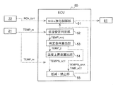
- the ECU 50 performs various controls of the engine 10, the fuel injection device 33, the urea water injection device 60, and the like, and includes a known CPU, ROM, RAM, input port, output port, and the like. Further, as shown in FIG. 2, the ECU 50 partially includes a NOx purification control unit 51, a low temperature stability determination unit 52, a determination condition calculation unit 53, a temperature increase rate calculation unit 54, and a reduction / prohibition unit 55. As a functional element. In the present embodiment, these functional elements are described as being included in the ECU 50, which is an integral piece of hardware. However, any one of these functional elements may be provided in separate hardware.
- the NOx purification control unit 51 feedback-controls the urea water injection amount of the urea water injection device 60 based on the SCR outlet NOx value NOx_OUT input from the NOx sensor 22. Further, the NOx purification control unit 51 also executes an abnormality diagnosis that issues an alarm when the NOx sensor 22 detects an abnormal value due to a significant decrease in the NOx purification performance of the SCR 41, a failure of the urea addition valve 61, or the like.
- the low temperature stability determination unit 52 determines whether or not the exhaust gas temperature flowing into the SCR 41 is stable in a predetermined low temperature state. More specifically, the low temperature stability determination unit 52 averages the SCR inlet temperature TEMP_IN detected by the exhaust temperature sensor 21 within a predetermined period, thereby obtaining the average temperature TEMP_AVE (moving average) within the predetermined period in real time. calculate. Then, (see time T0 ⁇ T1 of FIG. 3) If the average temperature TEMP _ave the calculated is equal to or less than the predetermined low temperature determination temperature TEMP _1, it determines that the low temperature stability of the exhaust gas temperature flowing into the SCR41.
- the low-temperature determination temperature TEMP _1 is preferably set in the range of, for example, about 190 ⁇ 200 ° C..
- the determination condition calculation unit 53 is used for high temperature determination, injection amount reduction / prohibition of diagnosis, which will be described later, (1) high temperature determination temperature TEMP_2 , (2) upper limit temperature The increase rate TEMP% _MAX , (3) the longest standby time TIME_UP , and (4) the processing inhibition time TIME_ACT are calculated.
- High temperature judgment temperature TEMP _2 is an exhaust temperature immediately before the NH3-slip occurs SCR41, is calculated according to the average temperature TEMP _ave.
- the upper limit temperature increase rate TEMP% _MAX is an exhaust temperature increase rate at which NH3 slip may occur in the SCR 41 , and is calculated according to the average temperature TEMP_AVE .
- Longest standby time TIME _up when the exhaust gas temperature has not reached the high temperature judgment temperature TEMP _2, a waiting time to initialize the high-temperature determination temperature TEMP _2 etc., are calculated in accordance with the average temperature TEMP _ave Alternatively, it is set as a predetermined arbitrary time.
- the processing prohibition time TIME_ACT is a time for reducing the urea water injection amount and prohibiting abnormality diagnosis in order to prevent further NH3 slip and erroneous diagnosis when the exhaust gas temperature rapidly rises, and the average temperature TEMP_AVE is The lower the value, the longer it is set.
- Temperature increase rate calculating unit 54 calculates the temperature rise rate in SCR inlet temperature TEMP _IN detected by the exhaust temperature sensor 21 rises from the low temperature determination temperature TEMP _1 to high temperature determination temperature TEMP _2. More specifically, time T1 ⁇ the exhaust temperature SCR inlet temperature TEMP _IN detected by the sensor 21 is low determination temperature TEMP arrival time _1 from the point of exceeding the until it reaches the high temperature determination temperature TEMP _2 TIME _1 ( Figure 3 T2 see) together with clocking by ECU50 internal timer, by dividing the temperature rise ⁇ TEMP obtained by subtracting the low-temperature determination temperature TEMP _1 from high temperature judgment temperature TEMP _2 in arrival time tIME _1, calculates the actual temperature increase rate TEMP% _ACT To do.
- the reduction / prohibition unit 55 reduces the urea water injection amount by the NOx purification control unit 51 and prohibits abnormality diagnosis when there is a possibility of NH3 slip. More specifically, if the actual temperature increase rate TEMP% _ACT calculated by the temperature increase rate calculation unit 54 is equal to or higher than the upper limit temperature increase rate TEMP% _MAX that may cause NH3 slip, the SCR inlet temperature TEMP_IN is high. determination (see time T2 ⁇ T3 in FIG. 3) temperature TEMP _2 from when he exceeds to the processing prohibition time tIME _ACT has elapsed, it prohibits the abnormality diagnosis with reducing urea water injection amount. This effectively prevents NH3 slip and erroneous diagnosis when the exhaust temperature suddenly rises.
- step (hereinafter, simply referred to as “S”) 100 the exhaust temperature flowing into the SCR 41 based on the average temperature TEMP_AVE obtained by moving average of the SCR inlet temperature TEMP_IN detected by the exhaust temperature sensor 21 within a predetermined period. Is determined to be stable in a predetermined low temperature state. If the average temperature TEMP _ave is less cold judgment temperature TEMP _1 (Yes), the exhaust gas temperature flowing into the SCR41 is it is determined that the low temperature stability, the control proceeds to S110.
- S the average temperature TEMP_AVE obtained by moving average of the SCR inlet temperature TEMP_IN detected by the exhaust temperature sensor 21 within a predetermined period. Is determined to be stable in a predetermined low temperature state. If the average temperature TEMP _ave is less cold judgment temperature TEMP _1 (Yes), the exhaust gas temperature flowing into the SCR41 is it is determined that the low temperature stability, the control proceeds to S110.
- SCR inlet temperature TEMP _IN detected by the exhaust temperature sensor 21 whether or not exceeded the low temperature determination temperature TEMP _1 is determined. If SCR inlet temperature TEMP _IN exceeds the low determination temperature TEMP _1 (Yes), the process proceeds to S130 to start the time measurement by the timer.
- SCR inlet temperature TEMP _IN detected by the exhaust temperature sensor 21 whether or not reached a high temperature judgment temperature TEMP _2 is determined. If SCR inlet temperature TEMP _IN does not reach the high temperature determination temperature TEMP _2 (No), the process proceeds to S140.
- the count time TIME _2 timer started from S120 whether reaches the maximum waiting time TIME _up is determined. If measured time TIME _2 has reached the maximum waiting time TIME _UP (Yes), the gradual because the temperature rise in a by NH3 slip is unlikely to occur, this control various judgments calculated in S110 proceeds to S300 The condition is initialized and returned.
- SCR inlet temperature TEMP _IN has reached the high temperature determination temperature TEMP _2 in S130 (Yes)
- the process proceeds to S200.
- step S210 it is determined whether there is a possibility that NH3 slip may occur in the SCR 41 due to a rapid temperature rise. If the actual temperature increase rate TEMP% _ACT calculated in S200 is less than the upper limit temperature increase rate TEMP% _MAX (No), this is a gradual temperature increase and the possibility of NH3 slip is low, so this control proceeds to S300. In step S110, various determination conditions calculated in step S110 are initialized and returned. On the other hand, if the actual temperature increase rate TEMP% _ACT is equal to or higher than the upper limit temperature increase rate TEMP% _MAX (Yes), the possibility of NH3 slip is high, and thus the present control proceeds to S220.
- the urea water injection amount by the NOx purification control unit 51 is reduced until the processing prohibition time TIME_ACT elapses from the time of S130 in order to prevent an excessive NH3 slip from being generated due to a rapid temperature increase and a misdiagnosis. And abnormal diagnosis is prohibited. Thereafter, when the processing prohibition time TIME_ACT elapses, the present control proceeds to S300, and the various determination conditions calculated in S110 are initialized and returned.
- the upper limit temperature increase rate actual temperature increase rate TEMP% _ACT to SCR inlet temperature TEMP _IN reaches from the low temperature determination temperature TEMP _1 high temperature determination temperature TEMP _2 indicates the possibility of NH3 slip If TEMP% _MAX or more, the urea water injection amount is reduced and the abnormality diagnosis is prohibited until the processing prohibition time TIME_ACT elapses. Accordingly, it is possible to reliably prevent the occurrence of NH3 slip and erroneous diagnosis when the exhaust gas temperature rapidly rises, such as during DPF forced regeneration. Moreover, since excessive injection of urea water is prevented, exhaust pipe corrosion caused by urea water adhesion or the like, performance deterioration of the SCR 41, and the like can be effectively suppressed.
- the urea water injection amount is reduced.
- the NH3 adsorption amount of the SCR 41 is close to the adsorption possible amount, the urea water injection is temporarily interrupted. Also good.
- the engine 10 is not limited to a diesel engine, and can be widely applied to other internal combustion engines such as a gasoline engine.
Landscapes
- Engineering & Computer Science (AREA)
- Chemical & Material Sciences (AREA)
- Chemical Kinetics & Catalysis (AREA)
- Combustion & Propulsion (AREA)
- Health & Medical Sciences (AREA)
- Mechanical Engineering (AREA)
- General Engineering & Computer Science (AREA)
- Environmental & Geological Engineering (AREA)
- Analytical Chemistry (AREA)
- General Chemical & Material Sciences (AREA)
- Oil, Petroleum & Natural Gas (AREA)
- Biomedical Technology (AREA)
- Toxicology (AREA)
- Exhaust Gas After Treatment (AREA)
- Exhaust Gas Treatment By Means Of Catalyst (AREA)
Abstract
排気浄化システムに関し、排気温度が急上昇した際のNH3スリップや誤診断を効果的に防止する。SCR(41)と、SCR(41)の下流側に設けられたNOxセンサ(22)と、NOxセンサ(22)の検出値に基づいてSCR(41)への尿素水噴射量を制御すると共に異常診断を行うNOx浄化制御部(51)とを備える排気浄化システムであって、SCR(41)に流入する排気温度を取得する排気温度センサ(21)と、排気温度センサ(21)で取得される排気温度が所定の第1温度から第2温度に到達するまでの温度上昇率を算出する温度上昇率算出部(54)と、温度上昇率算出部(54)で算出された温度上昇率が所定の判定閾値よりも高い場合に、NOx浄化制御部(51)による異常診断を禁止する禁止部(55)とを備えた。
Description
本発明は、排気浄化システムに関し、特に、排気中のNOxを還元浄化する選択的還元触媒(以下、SCR)を備えた排気浄化システムに関する。
従来、尿素水から加水分解されて生成されるアンモニア(以下、NH3)を還元剤として排気中のNOxを選択的に還元浄化するSCRを備えた排気浄化システムが知られている。このような排気浄化システムでは、SCRの排気下流側に設けたNOxセンサのセンサ値に基づいて、排気中のNOx値が目標値となるように尿素水噴射量をフィードバック制御している(例えば、特許文献1,2参照)。
ところで、SCRのNH3吸着可能量は、触媒温度の上昇に伴って低下する傾向がある。このため、ディーゼル・パティキュレイト・フィルタ(以下、DPF)の強制再生等によって排気温度が急上昇すると、SCRからNH3の一部が離脱して下流側に放出されるいわゆるNH3スリップを引き起こす可能性がある。
一般的なNOxセンサはNOxとNH3とを区別することができないため、NH3スリップが生じると、NOxセンサは高いNOx値を示すことになる。このため、尿素水噴射量をNOxセンサのセンサ値に基づいてフィードバック制御するシステムでは、NH3スリップを過大なNOxの排出と誤認識して尿素水噴射量を過剰に増加させる可能性があり、更なるNH3スリップを引き起こす課題がある。また、NOxセンサのセンサ値に基づいて異常診断等を行うシステムでは、NH3スリップを過大なNOxの排出と誤認識することで、尿素水噴射の停止や異常警報を発する等の誤診断を招く課題がある。
本発明の目的は、排気温度が急上昇した際のNH3スリップや誤診断を効果的に防止することができる排気浄化システムを提供することにある。
上述の目的を達成するため、本発明の排気浄化システムは、内燃機関の排気通路に設けられて尿素水から生成されるアンモニアを還元剤として排気中のNOxを浄化する選択的還元触媒と、該選択的還元触媒よりも下流側の排気通路に設けられたNOxセンサと、該NOxセンサの検出値に基づいて前記選択的還元触媒への尿素水噴射量を制御すると共に異常診断を行う制御手段とを備える排気浄化システムであって、前記選択的還元触媒に流入する排気温度を取得する排気温度取得手段と、前記排気温度取得手段で取得される排気温度が所定の第1温度から該第1温度よりも高い所定の第2温度に到達するまでの温度上昇率を算出する温度上昇率算出手段と、前記温度上昇率算出手段で算出された温度上昇率が所定の判定閾値よりも高い場合に、前記制御手段による異常診断を禁止する禁止手段とを備えることを特徴とする。
また、前記排気温度取得手段で所定期間内に取得される排気温度を平均化した平均温度を算出すると共に、該平均温度が前記第1温度以下であれば低温安定と判定する低温判定手段をさらに備え、前記温度上昇率算出手段は、前記低温判定手段によって低温安定と判定され、且つ前記排気温度取得手段によって取得される排気温度が前記第1温度を超えると、前記温度上昇率の算出を開始することが好ましい。
また、前記温度上昇率算出手段で算出された温度上昇率が所定の判定閾値よりも高い場合に、前記制御手段による尿素水噴射量を低減する低減手段をさらに備え、前記禁止手段は、異常診断の禁止を前記平均温度に応じて設定される所定期間継続すると共に、前記低減手段は、尿素水噴射量の低減を前記平均温度に応じて設定される所定期間継続することが好ましい。
また、前記禁止手段は、所定の待機時間内に前記排気温度取得手段で取得される排気温度が前記第1温度から前記第2温度に到達しなかった場合は異常診断の禁止を実行せず、前記低減手段は、所定の待機時間内に前記排気温度取得手段で取得される排気温度が前記第1温度から前記第2温度に到達しなかった場合は尿素水噴射量の低減を実行しないことが好ましい。
また、前記第2温度は、前記選択的還元触媒に吸着されたアンモニアの少なくとも一部が離脱してスリップする温度よりも低い温度で設定されることが好ましい。
以下、添付図面に基づいて、本発明の一実施形態に係る排気浄化システムを説明する。同一の部品には同一の符号を付してあり、それらの名称及び機能も同じである。したがって、それらについての詳細な説明は繰返さない。
図1に示すように、ディーゼルエンジン(以下、単にエンジンという)10の排気マニホールド10bには、排気を大気に導出する排気通路11が接続されている。この排気通路11には、排気上流側から順に、前段後処理装置30、後段後処理装置40等が設けられている。
前段後処理装置30は、触媒ケース30a内に上流側から順に酸化触媒(以下、DOC)31、DPF32を配置して構成されている。また、DOC31よりも上流側の排気通路11には、燃料噴射装置(燃料添加弁)33が設けられている。
燃料噴射装置33は、電子制御ユニット(以下、ECU)50から入力される指示信号に応じて、排気通路11内に未燃燃料(主にHC)を噴射する。なお、エンジン10の多段噴射によるポスト噴射を用いる場合は、この燃料噴射装置33を省略してもよい。
DOC31は、例えば、コーディエライトハニカム構造体等のセラミック製担体表面に触媒成分を担持して形成されている。DOC31は、燃料噴射装置33又はポスト噴射によってHCが供給されると、これを酸化して排気温度を上昇させる。
DPF32は、例えば、多孔質性の隔壁で区画された多数のセルを排気の流れ方向に沿って配置し、これらセルの上流側と下流側とを交互に目封止して形成されている。DPF32は、排気中のPMを隔壁の細孔や表面に捕集すると共に、PM堆積量が所定量に達すると、これを燃焼除去するいわゆる強制再生が実行される。強制再生は、燃料噴射装置33又はポスト噴射によってDOC31に未燃燃料(HC)を供給し、DPF32に流入する排気温度をPM燃焼温度まで昇温することで行われる。
後段後処理装置40は、ケース40a内に収容されたSCR41を備えて構成されている。また、SCR41よりも上流側の排気通路11には、尿素水噴射装置60及び、排気温度センサ21が設けられ、SCR41よりも下流側の排気通路11には、NOxセンサ22が設けられている。
尿素水噴射装置60は、ECU50から入力される指示信号に応じて尿素添加弁61を開閉動作させることで、SCR41よりも上流側の排気通路11内に、尿素水タンク62内から尿素水ポンプ63によって圧送される尿素水を噴射する。噴射された尿素水は排気熱により加水分解されてNH3に生成され、下流側のSCR41に還元剤として供給される。
SCR41は、例えば、ハニカム構造体等のセラミック製担体表面にゼオライト等を担持して形成されており、多孔質性の隔壁で区画された多数のセルを備えて構成されている。SCR41は、還元剤として供給されるNH3を吸着すると共に、吸着したNH3で通過する排気中からNOxを選択的に還元浄化する。
排気温度センサ21は、本発明の排気温度取得手段の一例であって、SCR41に流入する排気温度(以下、SCR入口温度TEMP_IN)を検出する。NOxセンサ22は、SCR41を通過した排気中のNOx値(以下、SCR出口NOx値NOx_OUT)を検出する。これら各種センサ21,22のセンサ値は、電気的に接続されたECU50に送信される。
ECU50は、エンジン10や燃料噴射装置33、尿素水噴射装置60等の各種制御を行うもので、公知のCPUやROM、RAM、入力ポート、出力ポート等を備えて構成されている。また、ECU50は、図2に示すように、NOx浄化制御部51と、低温安定判定部52と、判定条件算出部53と、温度上昇率算出部54と、低減・禁止部55とを一部の機能要素として有する。これら各機能要素は、本実施形態では一体のハードウェアであるECU50に含まれるものとして説明するが、これらのいずれか一部を別体のハードウェアに設けることもできる。
NOx浄化制御部51は、NOxセンサ22から入力されるSCR出口NOx値NOx_OUTに基づいて尿素水噴射装置60の尿素水噴射量をフィードバック制御する。また、NOx浄化制御部51は、SCR41のNOx浄化性能の大幅な低下や尿素添加弁61の故障等によってNOxセンサ22が異常値を検出すると警報を発する異常診断も実行する。
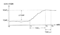
低温安定判定部52は、排気温度センサ21から入力されるSCR入口温度TEMP_INに基づいて、SCR41に流入する排気温度が所定の低温状態で安定しているか否かを判定する。より詳しくは、低温安定判定部52は、排気温度センサ21が所定期間内に検出したSCR入口温度TEMP_INを平均化することで、当該所定期間内の平均温度TEMP_AVE(移動平均)をリアルタイムで算出する。そして、算出した平均温度TEMP_AVEが所定の低温判定温度TEMP_1以下であれば(図3の時刻T0~T1参照)、SCR41に流入する排気温度を低温安定と判定する。なお、低温判定温度TEMP_1は、例えば約190~200℃の範囲で設定されることが好ましい。
判定条件算出部53は、低温安定判定部52によって低温安定と判定された際に、後述する高温判定や噴射量低減・診断禁止等に用いる(1)高温判定温度TEMP_2、(2)上限温度上昇率TEMP%_MAX、(3)最長待機時間TIME_UP、(4)処理禁止時間TIME_ACTを算出する。
高温判定温度TEMP_2は、SCR41でNH3スリップが生じる直前の排気温度であって、平均温度TEMP_AVEに応じて算出される。上限温度上昇率TEMP%_MAXは、SCR41でNH3スリップが発生する可能性のある排気温度上昇率であって、平均温度TEMP_AVEに応じて算出される。最長待機時間TIME_UPは、排気温度が高温判定温度TEMP_2まで到達しなかった場合に、高温判定温度TEMP_2等を初期化するための待機時間であって、平均温度TEMP_AVEに応じて算出されるか、あるいは、予め定めた任意の時間として設定される。処理禁止時間TIME_ACTは、排気温度の急上昇時に、更なるNH3スリップや誤診断を防ぐために、尿素水噴射量を低減し、且つ異常診断を禁止するための時間であって、平均温度TEMP_AVEが低くなるほど長く設定される。
温度上昇率算出部54は、排気温度センサ21で検出されるSCR入口温度TEMP_INが低温判定温度TEMP_1から高温判定温度TEMP_2まで上昇した際の温度上昇率を算出する。より詳しくは、排気温度センサ21で検出されるSCR入口温度TEMP_INが低温判定温度TEMP_1を超えた時点から高温判定温度TEMP_2に到達するまでの到達時間TIME_1(図3の時刻T1~T2参照)をECU50内蔵のタイマによって計時すると共に、高温判定温度TEMP_2から低温判定温度TEMP_1を減算した温度上昇幅ΔTEMPを到達時間TIME_1で除算することで、実温度上昇率TEMP%_ACTを算出する。
低減・禁止部55は、NH3スリップの発生の可能性がある場合に、NOx浄化制御部51による尿素水噴射量を低減させると共に異常診断を禁止する。より詳しくは、温度上昇率算出部54で算出された実温度上昇率TEMP%_ACTがNH3スリップを発生させる可能性がある上限温度上昇率TEMP%_MAX以上であれば、SCR入口温度TEMP_INが高温判定温度TEMP_2を超えた時点から処理禁止時間TIME_ACTが経過するまで(図3の時刻T2~T3参照)、尿素水噴射量を低減させると共に異常診断を禁止する。これにより、排気温度急上昇時のNH3スリップや誤診断が効果的に防止される。
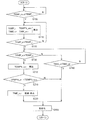
次に、図4に基づいて、本実施形態の排気浄化システムによる制御フローを説明する。なお、図4のフローは、NOx浄化制御部51による尿素水噴射制御及び異常診断と並行して実行される。
ステップ(以下、ステップを単にSと記載する)100では、所定期間内に排気温度センサ21で検出されるSCR入口温度TEMP_INを移動平均した平均温度TEMP_AVEに基づいて、SCR41に流入する排気温度が所定の低温状態で安定しているか否かが判定される。平均温度TEMP_AVEが低温判定温度TEMP_1以下の場合(Yes)、SCR41に流入する排気温度は低温安定と判定されて、本制御はS110に進む。
S110では、S100で算出された低温状態の平均温度TEMP_AVEに基づいて、高温判定等に用いる(1)高温判定温度TEMP_2、(2)上限温度上昇率TEMP%_MAX、(3)最長待機時間TIME_UP、(4)処理禁止時間TIME_ACTが算出される。
S120では、排気温度センサ21で検出されるSCR入口温度TEMP_INが低温判定温度TEMP_1を超えたか否かが判定される。SCR入口温度TEMP_INが低温判定温度TEMP_1を超えた場合(Yes)は、タイマによる計時を開始してS130に進む。
S130では、排気温度センサ21で検出されるSCR入口温度TEMP_INが高温判定温度TEMP_2に達したか否かが判定される。SCR入口温度TEMP_INが高温判定温度TEMP_2に達しない場合(No)は、S140に進む。
S140では、S120から開始されたタイマの計時時間TIME_2が最長待機時間TIME_UPに達したか否かが判定される。計時時間TIME_2が最長待機時間TIME_UPに達した場合(Yes)は、緩やかな温度上昇であってNH3スリップが発生する可能性は低いため、本制御はS300に進んでS110で算出した各種判定条件を初期化してリターンされる。
S130でSCR入口温度TEMP_INが高温判定温度TEMP_2に達した場合(Yes)はS200に進む。S200では、S120からS130までの温度上昇幅ΔTEMP(=TEMP2-TEMP1)をタイマによって計時した到達時間TIME_1で除算することで、実温度上昇率TEMP%_ACTが算出される。
S210では、急激な温度上昇によってSCR41でNH3スリップが発生する可能性があるか否かの判定を実行する。S200で算出した実温度上昇率TEMP%_ACTが上限温度上昇率TEMP%_MAX未満(No)であれば、緩やかな温度上昇であって、NH3スリップの可能性は低いため、本制御はS300に進んでS110で算出した各種判定条件を初期化してリターンされる。一方、実温度上昇率TEMP%_ACTが上限温度上昇率TEMP%_MAX以上(Yes)であれば、NH3スリップの可能性が高いため、本制御はS220に進む。
S220では、急激な温度上昇に伴う過大なNH3スリップの発生や誤診断を防止するために、S130の時点から処理禁止時間TIME_ACTが経過するまで、NOx浄化制御部51による尿素水噴射量を低減させると共に異常診断を禁止する。その後、処理禁止時間TIME_ACTが経過すると、本制御はS300に進んでS110で算出した各種判定条件を初期化してリターンされる。
次に、本実施形態に係る排気浄化システムの作用効果を説明する。
DPF強制再生の開始時等、排気温度が低温から高温に急上昇すると(図5(A)の時刻T1~T2参照)、SCR41のNH3吸着能力の低下によってNH3スリップが発生する(図5(A)の領域A参照)。NOxセンサ22はNH3とNOxとを区別できないため、NOxセンサ22のセンサ値に基づいて尿素水噴射量をフィードバック制御するシステムでは、実際のNOx値よりも高いNOx値と誤認識して尿素水噴射量を増加させ(図5(A)の時刻T2~T3参照)、更なるNH3スリップを引き起こす可能性がある。
また、排気温度の急上昇によって過大なNH3スリップが発生すると(図5(B)の領域A参照)、NH3とNOxとを区別できないNOxセンサ22は異常値を検出する(図5(B)のB点参照)。このため、NOxセンサ22のセンサ値に基づいて異常診断を行うシステムでは、過大なNOxが排出されているものと誤認識して、尿素水噴射の停止(図5(B)の時刻T3参照)や警報を発する等の誤診断を行う可能性がある。
本実施形態の排気浄化システムは、SCR入口温度TEMP_INが低温判定温度TEMP_1から高温判定温度TEMP_2に到達するまでの実温度上昇率TEMP%_ACTがNH3スリップの可能性を示す上限温度上昇率TEMP%_MAX以上であれば、処理禁止時間TIME_ACTが経過するまで尿素水噴射量を低減させると共に異常診断を禁止するように構成されている。したがって、DPF強制再生時等、排気温度急上昇時のNH3スリップの発生及び誤診断を確実に防止することができる。また、尿素水の過剰噴射が防止されるため、尿素水付着等によって引き起こされる排気管腐食やSCR41の性能劣化等を効果的に抑制することができる。
なお、本発明は、上述の実施形態に限定されるものではなく、本発明の趣旨を逸脱しない範囲で、適宜変形して実施することが可能である。
例えば、NH3スリップの可能性がある場合は尿素水噴射量を低減するものとしたが、SCR41のNH3吸着量が吸着可能量に近い場合は尿素水噴射を一時的に中断するように構成してもよい。また、エンジン10はディーゼルエンジンに限定されず、ガソリンエンジン等の他の内燃機関にも広く適用することが可能である。
Claims (5)
- 内燃機関の排気通路に設けられて尿素水から生成されるアンモニアを還元剤として排気中のNOxを浄化する選択的還元触媒と、該選択的還元触媒よりも下流側の排気通路に設けられたNOxセンサと、該NOxセンサの検出値に基づいて前記選択的還元触媒への尿素水噴射量を制御すると共に異常診断を行う制御手段とを備える排気浄化システムであって、
前記選択的還元触媒に流入する排気温度を取得する排気温度取得手段と、
前記排気温度取得手段で取得される排気温度が所定の第1温度から該第1温度よりも高い所定の第2温度に到達するまでの温度上昇率を算出する温度上昇率算出手段と、
前記温度上昇率算出手段で算出された温度上昇率が所定の判定閾値よりも高い場合に、前記制御手段による異常診断を禁止する禁止手段と、を備える
ことを特徴とする排気浄化システム。 - 前記排気温度取得手段で所定期間内に取得される排気温度を平均化した平均温度を算出すると共に、該平均温度が前記第1温度以下であれば低温安定と判定する低温判定手段をさらに備え、
前記温度上昇率算出手段は、前記低温判定手段によって低温安定と判定され、且つ前記排気温度取得手段によって取得される排気温度が前記第1温度を超えると、前記温度上昇率の算出を開始する
請求項1に記載の排気浄化システム。 - 前記温度上昇率算出手段で算出された温度上昇率が所定の判定閾値よりも高い場合に、前記制御手段による尿素水噴射量を低減する低減手段をさらに備え、
前記禁止手段は、異常診断の禁止を前記平均温度に応じて設定される所定期間継続すると共に、前記低減手段は、尿素水噴射量の低減を前記平均温度に応じて設定される所定期間継続する
請求項2に記載の排気浄化システム。 - 前記禁止手段は、所定の待機時間内に前記排気温度取得手段で取得される排気温度が前記第1温度から前記第2温度に到達しなかった場合は異常診断の禁止を実行せず、
前記低減手段は、所定の待機時間内に前記排気温度取得手段で取得される排気温度が前記第1温度から前記第2温度に到達しなかった場合は尿素水噴射量の低減を実行しない
請求項3に記載の排気浄化システム。 - 前記第2温度は、前記選択的還元触媒に吸着されたアンモニアの少なくとも一部が離脱してスリップする温度よりも低い温度で設定される
請求項1から4の何れか一項に記載の排気浄化システム。
Priority Applications (3)
| Application Number | Priority Date | Filing Date | Title |
|---|---|---|---|
| EP15780707.4A EP3133257B1 (en) | 2014-04-16 | 2015-04-16 | Exhaust gas purification system |
| US15/304,828 US9943806B2 (en) | 2014-04-16 | 2015-04-16 | Exhaust gas purification system |
| CN201580020025.0A CN106715851B (zh) | 2014-04-16 | 2015-04-16 | 排气净化系统 |
Applications Claiming Priority (2)
| Application Number | Priority Date | Filing Date | Title |
|---|---|---|---|
| JP2014-084620 | 2014-04-16 | ||
| JP2014084620A JP6330444B2 (ja) | 2014-04-16 | 2014-04-16 | 排気浄化システム |
Publications (1)
| Publication Number | Publication Date |
|---|---|
| WO2015159954A1 true WO2015159954A1 (ja) | 2015-10-22 |
Family
ID=54324155
Family Applications (1)
| Application Number | Title | Priority Date | Filing Date |
|---|---|---|---|
| PCT/JP2015/061732 Ceased WO2015159954A1 (ja) | 2014-04-16 | 2015-04-16 | 排気浄化システム |
Country Status (5)
| Country | Link |
|---|---|
| US (1) | US9943806B2 (ja) |
| EP (1) | EP3133257B1 (ja) |
| JP (1) | JP6330444B2 (ja) |
| CN (1) | CN106715851B (ja) |
| WO (1) | WO2015159954A1 (ja) |
Families Citing this family (27)
| Publication number | Priority date | Publication date | Assignee | Title |
|---|---|---|---|---|
| JP2596377B2 (ja) | 1994-07-25 | 1997-04-02 | 株式会社大林組 | 水中構造物の洗掘防止工法 |
| GB2548040B (en) | 2014-12-31 | 2020-11-25 | Cummins Emission Solutions Inc | Compact side inlet and outlet exhaust aftertreatment system |
| US10436097B2 (en) | 2014-12-31 | 2019-10-08 | Cummins Emission Solutions Inc. | Close coupled single module aftertreatment system |
| WO2016109320A1 (en) | 2014-12-31 | 2016-07-07 | Cummins Emission Solutions, Inc. | Single module integrated aftertreatment module |
| US10267199B2 (en) | 2015-07-28 | 2019-04-23 | Cummins Emission Solutions Inc. | Angled sensor mount for use with a single module aftertreatment system or the like |
| USD794100S1 (en) * | 2015-09-28 | 2017-08-08 | Cummins Emission Solutions Inc. | Aftertreatment system housing |
| ES2828028T3 (es) * | 2015-09-29 | 2021-05-25 | Carrier Corp | Sistema de refrigeración de transporte que comprende una unidad de refrigeración y un motor diésel |
| JP6731893B2 (ja) * | 2017-07-31 | 2020-07-29 | ヤンマーパワーテクノロジー株式会社 | 作業車両 |
| DE102017010825B4 (de) * | 2017-11-23 | 2025-11-13 | Mercedes-Benz Group AG | Verfahren zum Betreiben einer Abgasanlage mit einem ersten SCR-Katalysator und einem zweiten SCR-Katalysator |
| KR102518593B1 (ko) * | 2018-05-24 | 2023-04-05 | 현대자동차 주식회사 | SDPF의 NOx 정화 효율 보정 방법 |
| CN112431655A (zh) * | 2019-08-26 | 2021-03-02 | 北汽福田汽车股份有限公司 | 车辆后处理系统异常确定方法、装置、存储介质及车辆 |
| US11828210B2 (en) | 2020-08-20 | 2023-11-28 | Denso International America, Inc. | Diagnostic systems and methods of vehicles using olfaction |
| US12251991B2 (en) | 2020-08-20 | 2025-03-18 | Denso International America, Inc. | Humidity control for olfaction sensors |
| US12269315B2 (en) | 2020-08-20 | 2025-04-08 | Denso International America, Inc. | Systems and methods for measuring and managing odor brought into rental vehicles |
| US12377711B2 (en) | 2020-08-20 | 2025-08-05 | Denso International America, Inc. | Vehicle feature control systems and methods based on smoking |
| US11881093B2 (en) | 2020-08-20 | 2024-01-23 | Denso International America, Inc. | Systems and methods for identifying smoking in vehicles |
| US11636870B2 (en) | 2020-08-20 | 2023-04-25 | Denso International America, Inc. | Smoking cessation systems and methods |
| US11932080B2 (en) | 2020-08-20 | 2024-03-19 | Denso International America, Inc. | Diagnostic and recirculation control systems and methods |
| US11813926B2 (en) | 2020-08-20 | 2023-11-14 | Denso International America, Inc. | Binding agent and olfaction sensor |
| US11760169B2 (en) | 2020-08-20 | 2023-09-19 | Denso International America, Inc. | Particulate control systems and methods for olfaction sensors |
| US12017506B2 (en) | 2020-08-20 | 2024-06-25 | Denso International America, Inc. | Passenger cabin air control systems and methods |
| US11760170B2 (en) | 2020-08-20 | 2023-09-19 | Denso International America, Inc. | Olfaction sensor preservation systems and methods |
| CN112814770B (zh) * | 2020-12-31 | 2022-04-05 | 潍柴动力股份有限公司 | 并联式scr系统的均匀性评价方法及装置 |
| CN114046197B (zh) * | 2021-10-11 | 2023-03-21 | 潍柴动力股份有限公司 | 一种废气处理的方法、装置及可读存储介质 |
| CN116220869B (zh) * | 2022-12-08 | 2025-09-19 | 潍柴动力股份有限公司 | 尿素喷射系统的控制方法、控制装置和尿素喷射系统 |
| CN117386495B (zh) * | 2023-11-27 | 2024-11-05 | 一汽解放汽车有限公司 | 一种车辆氮氧化物传感器的故障诊断方法、装置及设备 |
| CN119616636B (zh) * | 2024-12-09 | 2025-09-12 | 东风商用车有限公司 | 一种尿素异常消耗分析方法、装置及车辆 |
Citations (4)
| Publication number | Priority date | Publication date | Assignee | Title |
|---|---|---|---|---|
| JP2006242094A (ja) * | 2005-03-03 | 2006-09-14 | Hino Motors Ltd | 排気浄化装置 |
| JP2006274844A (ja) * | 2005-03-28 | 2006-10-12 | Mitsubishi Fuso Truck & Bus Corp | 内燃機関の排気浄化装置 |
| JP2010248925A (ja) * | 2009-04-10 | 2010-11-04 | Mazda Motor Corp | エンジン排気浄化装置 |
| JP2012036835A (ja) * | 2010-08-06 | 2012-02-23 | Mitsubishi Fuso Truck & Bus Corp | 排気浄化装置 |
Family Cites Families (11)
| Publication number | Priority date | Publication date | Assignee | Title |
|---|---|---|---|---|
| JP2003293738A (ja) | 2002-03-29 | 2003-10-15 | Mitsubishi Fuso Truck & Bus Corp | 内燃機関のNOx浄化装置 |
| JP4592504B2 (ja) * | 2005-06-09 | 2010-12-01 | 三菱ふそうトラック・バス株式会社 | 排気浄化装置 |
| ATE459407T1 (de) * | 2007-07-31 | 2010-03-15 | Delphi Tech Inc | System und verfahren zur selektiven steuerung einer katalytischen reduktion |
| FR2931201B1 (fr) * | 2008-05-16 | 2010-06-04 | Peugeot Citroen Automobiles Sa | Procede de correction de modeles d'emission d'oxydes d'azote |
| EP2123345B1 (de) * | 2008-05-23 | 2010-08-04 | Umicore AG & Co. KG | Vorrichtung zur Reinigung von Dieselabgasen |
| KR100962871B1 (ko) * | 2008-06-10 | 2010-06-09 | 현대자동차주식회사 | 이산화탄소 흡수액 재생방법 |
| WO2010082493A1 (ja) | 2009-01-16 | 2010-07-22 | トヨタ自動車株式会社 | 内燃機関の排気浄化装置 |
| JP2010180847A (ja) | 2009-02-09 | 2010-08-19 | Toyota Motor Corp | 排気浄化システムの故障診断装置 |
| SE536083C2 (sv) | 2011-08-31 | 2013-04-30 | Scania Cv Ab | Förfarande för att detektera reduktionsmedelskristaller i ett SCR-system och motsvarande SCR-system |
| JP2013181411A (ja) | 2012-02-29 | 2013-09-12 | Toyota Motor Corp | 内燃機関の排気浄化装置 |
| RU2597380C1 (ru) * | 2012-12-06 | 2016-09-10 | Тойота Дзидося Кабусики Кайся | Система определения неисправностей устройства очистки выхлопных газов |
-
2014
- 2014-04-16 JP JP2014084620A patent/JP6330444B2/ja not_active Expired - Fee Related
-
2015
- 2015-04-16 WO PCT/JP2015/061732 patent/WO2015159954A1/ja not_active Ceased
- 2015-04-16 EP EP15780707.4A patent/EP3133257B1/en active Active
- 2015-04-16 CN CN201580020025.0A patent/CN106715851B/zh active Active
- 2015-04-16 US US15/304,828 patent/US9943806B2/en active Active
Patent Citations (4)
| Publication number | Priority date | Publication date | Assignee | Title |
|---|---|---|---|---|
| JP2006242094A (ja) * | 2005-03-03 | 2006-09-14 | Hino Motors Ltd | 排気浄化装置 |
| JP2006274844A (ja) * | 2005-03-28 | 2006-10-12 | Mitsubishi Fuso Truck & Bus Corp | 内燃機関の排気浄化装置 |
| JP2010248925A (ja) * | 2009-04-10 | 2010-11-04 | Mazda Motor Corp | エンジン排気浄化装置 |
| JP2012036835A (ja) * | 2010-08-06 | 2012-02-23 | Mitsubishi Fuso Truck & Bus Corp | 排気浄化装置 |
Non-Patent Citations (1)
| Title |
|---|
| See also references of EP3133257A4 * |
Also Published As
| Publication number | Publication date |
|---|---|
| US20170043295A1 (en) | 2017-02-16 |
| EP3133257B1 (en) | 2018-09-19 |
| JP2015203399A (ja) | 2015-11-16 |
| CN106715851A (zh) | 2017-05-24 |
| EP3133257A4 (en) | 2017-10-18 |
| EP3133257A1 (en) | 2017-02-22 |
| CN106715851B (zh) | 2019-05-10 |
| JP6330444B2 (ja) | 2018-05-30 |
| US9943806B2 (en) | 2018-04-17 |
Similar Documents
| Publication | Publication Date | Title |
|---|---|---|
| JP6330444B2 (ja) | 排気浄化システム | |
| JP6248789B2 (ja) | 排気浄化システム | |
| JP6087580B2 (ja) | 内燃機関の排気浄化装置およびその排気浄化方法 | |
| JP2015059472A (ja) | 診断装置 | |
| EP2559876B1 (en) | Exhaust gas purification device, and control method for exhaust gas purification device | |
| JPWO2010079621A1 (ja) | 触媒通過成分判定装置および内燃機関の排気浄化装置 | |
| WO2014132839A1 (ja) | 内燃機関の排気浄化装置 | |
| JP6163996B2 (ja) | 診断装置 | |
| EP3135875B1 (en) | Exhaust purifying system | |
| EP3068988B1 (en) | Exhaust gas control apparatus and exhaust gas control method for engine | |
| JP6206065B2 (ja) | 排気浄化システム | |
| JP6398402B2 (ja) | 排気浄化システム | |
| JP6398401B2 (ja) | 排気浄化システム | |
| JP7167869B2 (ja) | 内燃機関の排気浄化装置 | |
| JP2018178734A (ja) | 内燃機関の排気浄化システム | |
| JP6790787B2 (ja) | 内燃機関の排気ガス浄化装置 | |
| JP2015059475A (ja) | 診断装置 | |
| JP2015068815A (ja) | 検出装置 |
Legal Events
| Date | Code | Title | Description |
|---|---|---|---|
| 121 | Ep: the epo has been informed by wipo that ep was designated in this application |
Ref document number: 15780707 Country of ref document: EP Kind code of ref document: A1 |
|
| NENP | Non-entry into the national phase |
Ref country code: DE |
|
| REEP | Request for entry into the european phase |
Ref document number: 2015780707 Country of ref document: EP |
|
| WWE | Wipo information: entry into national phase |
Ref document number: 15304828 Country of ref document: US Ref document number: 2015780707 Country of ref document: EP |