WO2015162779A1 - 排気再循環制御装置及び排気再循環制御方法 - Google Patents
排気再循環制御装置及び排気再循環制御方法 Download PDFInfo
- Publication number
- WO2015162779A1 WO2015162779A1 PCT/JP2014/061706 JP2014061706W WO2015162779A1 WO 2015162779 A1 WO2015162779 A1 WO 2015162779A1 JP 2014061706 W JP2014061706 W JP 2014061706W WO 2015162779 A1 WO2015162779 A1 WO 2015162779A1
- Authority
- WO
- WIPO (PCT)
- Prior art keywords
- exhaust gas
- recirculation
- gas recirculation
- passage
- recirculation control
- Prior art date
- Legal status (The legal status is an assumption and is not a legal conclusion. Google has not performed a legal analysis and makes no representation as to the accuracy of the status listed.)
- Ceased
Links
Images


Classifications
-
- F—MECHANICAL ENGINEERING; LIGHTING; HEATING; WEAPONS; BLASTING
- F02—COMBUSTION ENGINES; HOT-GAS OR COMBUSTION-PRODUCT ENGINE PLANTS
- F02D—CONTROLLING COMBUSTION ENGINES
- F02D41/00—Electrical control of supply of combustible mixture or its constituents
- F02D41/0025—Controlling engines characterised by use of non-liquid fuels, pluralities of fuels, or non-fuel substances added to the combustible mixtures
- F02D41/0047—Controlling exhaust gas recirculation [EGR]
- F02D41/005—Controlling exhaust gas recirculation [EGR] according to engine operating conditions
- F02D41/0052—Feedback control of engine parameters, e.g. for control of air/fuel ratio or intake air amount
-
- F—MECHANICAL ENGINEERING; LIGHTING; HEATING; WEAPONS; BLASTING
- F02—COMBUSTION ENGINES; HOT-GAS OR COMBUSTION-PRODUCT ENGINE PLANTS
- F02D—CONTROLLING COMBUSTION ENGINES
- F02D41/00—Electrical control of supply of combustible mixture or its constituents
- F02D41/0002—Controlling intake air
- F02D41/0007—Controlling intake air for control of turbo-charged or super-charged engines
-
- F—MECHANICAL ENGINEERING; LIGHTING; HEATING; WEAPONS; BLASTING
- F02—COMBUSTION ENGINES; HOT-GAS OR COMBUSTION-PRODUCT ENGINE PLANTS
- F02D—CONTROLLING COMBUSTION ENGINES
- F02D41/00—Electrical control of supply of combustible mixture or its constituents
- F02D41/02—Circuit arrangements for generating control signals
- F02D41/04—Introducing corrections for particular operating conditions
- F02D41/08—Introducing corrections for particular operating conditions for idling
-
- F—MECHANICAL ENGINEERING; LIGHTING; HEATING; WEAPONS; BLASTING
- F02—COMBUSTION ENGINES; HOT-GAS OR COMBUSTION-PRODUCT ENGINE PLANTS
- F02D—CONTROLLING COMBUSTION ENGINES
- F02D41/00—Electrical control of supply of combustible mixture or its constituents
- F02D41/02—Circuit arrangements for generating control signals
- F02D41/14—Introducing closed-loop corrections
- F02D41/16—Introducing closed-loop corrections for idling
-
- F—MECHANICAL ENGINEERING; LIGHTING; HEATING; WEAPONS; BLASTING
- F02—COMBUSTION ENGINES; HOT-GAS OR COMBUSTION-PRODUCT ENGINE PLANTS
- F02M—SUPPLYING COMBUSTION ENGINES IN GENERAL WITH COMBUSTIBLE MIXTURES OR CONSTITUENTS THEREOF
- F02M26/00—Engine-pertinent apparatus for adding exhaust gases to combustion-air, main fuel or fuel-air mixture, e.g. by exhaust gas recirculation [EGR] systems
- F02M26/02—EGR systems specially adapted for supercharged engines
- F02M26/04—EGR systems specially adapted for supercharged engines with a single turbocharger
- F02M26/05—High pressure loops, i.e. wherein recirculated exhaust gas is taken out from the exhaust system upstream of the turbine and reintroduced into the intake system downstream of the compressor
-
- F—MECHANICAL ENGINEERING; LIGHTING; HEATING; WEAPONS; BLASTING
- F02—COMBUSTION ENGINES; HOT-GAS OR COMBUSTION-PRODUCT ENGINE PLANTS
- F02M—SUPPLYING COMBUSTION ENGINES IN GENERAL WITH COMBUSTIBLE MIXTURES OR CONSTITUENTS THEREOF
- F02M26/00—Engine-pertinent apparatus for adding exhaust gases to combustion-air, main fuel or fuel-air mixture, e.g. by exhaust gas recirculation [EGR] systems
- F02M26/02—EGR systems specially adapted for supercharged engines
- F02M26/04—EGR systems specially adapted for supercharged engines with a single turbocharger
- F02M26/06—Low pressure loops, i.e. wherein recirculated exhaust gas is taken out from the exhaust downstream of the turbocharger turbine and reintroduced into the intake system upstream of the compressor
-
- F—MECHANICAL ENGINEERING; LIGHTING; HEATING; WEAPONS; BLASTING
- F02—COMBUSTION ENGINES; HOT-GAS OR COMBUSTION-PRODUCT ENGINE PLANTS
- F02M—SUPPLYING COMBUSTION ENGINES IN GENERAL WITH COMBUSTIBLE MIXTURES OR CONSTITUENTS THEREOF
- F02M26/00—Engine-pertinent apparatus for adding exhaust gases to combustion-air, main fuel or fuel-air mixture, e.g. by exhaust gas recirculation [EGR] systems
- F02M26/52—Systems for actuating EGR valves
- F02M26/64—Systems for actuating EGR valves the EGR valve being operated together with an intake air throttle
-
- F—MECHANICAL ENGINEERING; LIGHTING; HEATING; WEAPONS; BLASTING
- F02—COMBUSTION ENGINES; HOT-GAS OR COMBUSTION-PRODUCT ENGINE PLANTS
- F02D—CONTROLLING COMBUSTION ENGINES
- F02D41/00—Electrical control of supply of combustible mixture or its constituents
- F02D41/0002—Controlling intake air
- F02D2041/0017—Controlling intake air by simultaneous control of throttle and exhaust gas recirculation
-
- Y—GENERAL TAGGING OF NEW TECHNOLOGICAL DEVELOPMENTS; GENERAL TAGGING OF CROSS-SECTIONAL TECHNOLOGIES SPANNING OVER SEVERAL SECTIONS OF THE IPC; TECHNICAL SUBJECTS COVERED BY FORMER USPC CROSS-REFERENCE ART COLLECTIONS [XRACs] AND DIGESTS
- Y02—TECHNOLOGIES OR APPLICATIONS FOR MITIGATION OR ADAPTATION AGAINST CLIMATE CHANGE
- Y02T—CLIMATE CHANGE MITIGATION TECHNOLOGIES RELATED TO TRANSPORTATION
- Y02T10/00—Road transport of goods or passengers
- Y02T10/10—Internal combustion engine [ICE] based vehicles
- Y02T10/12—Improving ICE efficiencies
Definitions
- the present invention relates to an exhaust gas recirculation control device and an exhaust gas recirculation control method for an internal combustion engine.
- EGR exhaust gas recirculation
- the EGR device includes an EGR passage that branches from the exhaust passage and merges with the intake passage, and an EGR valve that opens and closes the flow path of the EGR passage.
- the EGR valve opens according to the target EGR rate, and the exhaust
- the configuration is such that EGR gas flows to the intake side using the differential pressure between the intake side and the intake side.
- the controller sets a target EGR rate in the operating state of the internal combustion engine, and controls the ignition timing according to the target EGR rate. Therefore, when the amount of EGR gas that actually passes through the EGR valve (actual EGR gas amount) is smaller than the target EGR gas amount, knocking occurs when the engine is operated at the ignition timing corrected on the assumption that the target EGR rate is reached. May occur.
- the above-described deviation between the target EGR gas amount and the actual EGR gas amount is likely to occur when the differential pressure between the exhaust side and the intake side is small.
- the pressure loss becomes smaller. For example, when the EGR valve is opened while the exhaust system is cold, the difference between the exhaust side and the intake side is low because the pressure of the exhaust passage is low. The pressure is reduced.
- the smaller the intake air amount the smaller the exhaust flow rate, making it difficult for the pressure on the exhaust side to increase.
- the same EGR rate is set regardless of the engine speed if the load is the same without considering the intake air amount. For example, the low rotation and high load region, that is, the load is high. However, in a region where the intake air amount is small, knocking due to the difference between the target EGR gas amount and the actual EGR gas amount is likely to occur.
- an object of the present invention is to provide an EGR control device that controls the EGR device so that the occurrence of knocking can be suppressed even when the difference between the target EGR rate and the actual EGR rate is likely to occur.
- the exhaust gas recirculation control device is configured to remove a part of the exhaust gas of the internal combustion engine from the exhaust passage downstream of the turbine of the turbocharger and from the compressor of the turbocharger.
- An exhaust gas recirculation passage that recirculates to the intake passage upstream of the intake air flow and downstream of the air flow meter, and a recirculation control valve that adjusts the amount of exhaust gas recirculated to the intake air passage.
- the exhaust gas recirculation control device has a recirculation rate setting means for setting a lower target recirculation rate as the intake air amount of the internal combustion engine is smaller, and controls the opening degree of the recirculation control valve according to the target recirculation rate. To do.
- FIG. 1 is a configuration diagram of an internal combustion engine system to which the present embodiment is applied.
- FIG. 2 is a diagram illustrating an example of the target EGR rate map.
- FIG. 3 is a diagram illustrating an example of a target EGR rate map according to the present embodiment.
- FIG. 4 is a diagram illustrating another example of the target EGR rate map according to the present embodiment.
- FIG. 1 is a configuration diagram of an internal combustion engine system to which an embodiment of the present invention is applied.
- an air flow meter 3 In the intake passage 2 of the internal combustion engine 1, an air flow meter 3, a compressor 4A of the turbocharger 4, a throttle chamber 5, and a collector tank 6 on the intercooler integrated side are arranged from the upstream side of the intake flow.
- the system includes a recirculation passage 13 that communicates the upstream side and the downstream side of the compressor 4A, and a recirculation valve 14 that opens during deceleration to return intake air from the downstream side to the upstream side of the compressor 4A.
- the turbine 4B, the manifold catalyst 8, and the underfloor catalyst 9 of the turbocharger 4 are arranged in the exhaust passage 7 from the upstream side of the exhaust flow.
- the present system includes a bypass passage 15 that communicates the upstream side and the downstream side of the turbine 4B, and a valve 16 that opens and closes the flow path of the bypass passage 15.
- the manifold catalyst 8 and the underfloor catalyst 9 are both exhaust purification catalyst devices.
- the manifold catalyst 8 is arranged at a position close to the downstream side of the turbine 4B so that the exhaust gas flows in as high as possible.
- the underfloor catalyst 9 has a larger capacity than the manifold catalyst 8 and is disposed under the floor of the vehicle.
- the system also includes an exhaust gas recirculation device (hereinafter also referred to as an “EGR device”).
- the EGR device branches from between the manifold catalyst 8 and the underfloor catalyst 9 in the exhaust passage 7 and joins the exhaust recirculation passage (hereinafter referred to as “the flow passage 3” upstream of the compressor 4A and downstream of the air flow meter 3 of the intake passage 2).
- a recirculation valve hereinafter also referred to as “EGR valve” 11 for adjusting the amount of exhaust gas (hereinafter also referred to as “EGR gas”) passing through the EGR passage 10. Consists of.
- an EGR gas cooler 12 that cools the EGR gas may be included.
- the EGR device of the present embodiment is a so-called low pressure EGR device that recirculates a part of the exhaust gas from the downstream side of the turbine 4B to the upstream side of the compressor 4A and the downstream side of the air flow meter 3.
- the internal combustion engine system described above further includes a crank angle sensor 18 that detects the rotational speed of the internal combustion engine 1 (hereinafter also referred to as the engine rotational speed) and an accelerator pedal opening sensor 19, and these sensors and the air flow meter 3. Is detected by the controller 100.
- the controller 100 executes ignition control, fuel injection control, throttle valve opening control, EGR device control (EGR control), and the like based on the read detection value.
- EGR control EGR device control
- the controller 100 first determines the target EGR rate by map search or the like based on the operating state (for example, engine speed and load), and controls the EGR valve 11 to an opening degree corresponding to the target EGR rate. A method for setting the target EGR rate will be described later.
- the opening degree of the EGR valve 11 corresponding to the target EGR rate is obtained by mapping the relationship between the target EGR rate and the opening degree of the EGR valve 11 in advance and searching this map.
- the controller 100 After determining the target EGR rate, the controller 100 sets the ignition timing based on the target EGR rate.
- FIG. 2 is a diagram showing an example of a known target EGR map.
- the target EGR rate is set from the viewpoint of knocking prevention and fuel efficiency improvement. If the load is the same, the target EGR rate is the same regardless of the engine speed, and the engine speed is the same. The target EGR rate increases as the load increases.
- the EGR device recirculates exhaust gas to the intake side using the differential pressure between the exhaust side and the intake side.
- the differential pressure between the exhaust side and the intake side is likely to increase because the intake side has a negative pressure.
- the low pressure EGR device since the intake side is atmospheric pressure, the lower the pressure on the exhaust side, the smaller the differential pressure, making it difficult to recirculate the exhaust gas.
- the pressure loss of the exhaust system decreases as the temperature of the exhaust system (manifold catalyst 8, underfloor catalyst 9, exhaust passage itself, etc.) decreases, the pressure in the exhaust passage 7 is difficult to increase when the exhaust system is at a low temperature.
- the amount of intake air decreases, and the exhaust flow rate decreases accordingly, making it difficult to increase the pressure on the exhaust side. As a result, differential pressure is less likely to occur.
- the target EGR rate is achieved because the differential pressure is small.
- the amount of EGR gas required for the recirculation is not recirculated, and the actual EGR rate becomes lower than the target EGR rate.
- the ignition timing is controlled to be advanced as the target EGR rate is larger, assuming that an EGR gas amount that can suppress the occurrence of knocking is introduced. Therefore, the larger the target EGR rate, the more likely knocking occurs when the target EGR rate and the actual EGR rate deviate.
- knocking is likely to occur in the low rotation high load region, particularly when the exhaust system is at a low temperature.
- knocking occurs, not only the deterioration of the internal combustion engine 1 is promoted, but in the case of a high-octane fuel specification vehicle, it is erroneously assumed that regular fuel is used even though high-octane fuel is used in the fuel property determination. May be judged.
- the ignition timing is retarded so that knocking does not occur even with regular fuel, and the output of the internal combustion engine 1 decreases, so that regions other than the low rotational speed region where knocking is difficult to occur The drivability will be reduced.
- the EGR rate set in the EGR map of FIG. 2 is a value that does not cause knocking even if there is a difference between the target EGR rate and the actual EGR rate, that is, the exhaust system is at a low temperature. There is a method to make it a small value on the assumption of.
- the target EGR rate is set, in a region where the differential pressure is likely to increase due to a large amount of intake air, such as in a high rotation region, the target EGR rate is smaller than necessary, and the fuel efficiency improvement effect by EGR control is reduced. It gets smaller.
- the target EGR rate is set as described below.
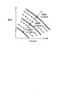
- FIG. 3 is a target EGR rate map used in this embodiment.
- the target EGR rate increases as the engine rotational speed increases at the same load, and the target EGR rate increases as the load increases at the same engine rotational speed.
- the curve which shows each EGR rate of FIG. 3 corresponds with an equal intake air amount curve. That is, in the target EGR rate map of FIG. 3, the target EGR rate based on the intake air amount is set. The larger the intake air amount, the larger the target EGR rate, and the smaller the intake air amount, the smaller the target EGR rate. ing.
- the air flow meter 3 causes the controller 100 so that the target EGR rate set in the target EGR rate map of FIG. 2 becomes the target EGR rate shown in the target EGR rate map of FIG. You may correct
- the smaller the intake air amount the larger the correction amount for reducing the target EGR rate.
- the larger the intake air amount the larger the correction amount for increasing the target EGR rate.
- the target EGR rate map of FIG. 3 has a lower target EGR rate in the low rotation speed region and a target in the high rotation speed region than the target EGR rate map of FIG.
- the EGR rate is increasing.
- the target EGR rate in the low rotation speed region is small, the target EGR rate can be easily achieved even if the differential pressure between the exhaust side and the intake side is small. Therefore, knocking in the low rotation and high load region as described above occurs. It becomes difficult to do.
- the target EGR rate map is not limited to that shown in FIG. 3, and the target EGR rate may be changed stepwise for each predetermined intake air amount range.
- the operation region is divided into region A, region B, and region C according to the intake air amount, and each region has a uniform target EGR rate, and a region with a larger intake air amount has a larger target.
- a map in which the EGR rate is set may be used.
- the target EGR rate map is such that the target EGR rate changes stepwise for each predetermined intake air amount range, the target EGR rate will not fluctuate if the operating state change amount is small. That is, fluctuations in the target EGR rate during operation are reduced. Thereby, it is possible to avoid complication of the ignition timing correction and the opening / closing operation of the EGR valve 11 accompanying the change in the target EGR rate.
Landscapes
- Engineering & Computer Science (AREA)
- Chemical & Material Sciences (AREA)
- Combustion & Propulsion (AREA)
- Mechanical Engineering (AREA)
- General Engineering & Computer Science (AREA)
- Exhaust-Gas Circulating Devices (AREA)
- Output Control And Ontrol Of Special Type Engine (AREA)
- Supercharger (AREA)
- Combined Controls Of Internal Combustion Engines (AREA)
Abstract
Description
Claims (3)
- 内燃機関の排気ガスの一部を、ターボ過給機のタービンよりも排気流れ下流側の排気通路から、ターボ過給機のコンプレッサよりも吸気流れ上流側かつエアフローメータより吸気流れ下流側の吸気通路に還流させる排気再循環通路と、
前記吸気通路に還流させる排気ガスの量を調整する再循環制御弁と、
を含む排気再循環装置を制御する排気再循環制御装置において、
前記内燃機関の吸入空気量が少ないほど低い目標再循環率を設定する再循環率設定手段を備え、
前記目標再循環率に応じて前記再循環制御弁の開度を制御する排気再循環制御装置。 - 請求項1に記載の排気再循環制御装置において、
前記再循環率設定手段は、前記目標再循環率を所定の吸入空気量範囲毎にステップ的に変化させる排気再循環制御装置。 - 内燃機関の排気ガスの一部を、ターボ過給機のコンプレッサよりも吸気流れ上流側かつエアフローメータより吸気流れ下流側の吸気通路に再循環させる排気再循環通路と、
前記吸気通路に再循環させる排気ガスの量を調整する再循環制御弁と、
を含む排気再循環装置を制御する排気再循環制御方法において、
前記内燃機関の吸入空気量が少ないほど低い目標再循環率を設定し、
前記目標再循環率に応じて前記再循環制御弁の開度を制御する排気再循環制御方法。
Priority Applications (5)
| Application Number | Priority Date | Filing Date | Title |
|---|---|---|---|
| JP2016514661A JP6210153B2 (ja) | 2014-04-25 | 2014-04-25 | 排気再循環制御装置及び排気再循環制御方法 |
| CN201480078163.XA CN106255819B (zh) | 2014-04-25 | 2014-04-25 | 排气再循环控制装置及排气再循环控制方法 |
| PCT/JP2014/061706 WO2015162779A1 (ja) | 2014-04-25 | 2014-04-25 | 排気再循環制御装置及び排気再循環制御方法 |
| EP14889919.8A EP3139026B1 (en) | 2014-04-25 | 2014-04-25 | Exhaust gas recirculation control device and exhaust gas recirculation control method |
| US15/305,518 US10100759B2 (en) | 2014-04-25 | 2014-04-25 | Exhaust gas recirculation control device and exhaust gas recirculation control method |
Applications Claiming Priority (1)
| Application Number | Priority Date | Filing Date | Title |
|---|---|---|---|
| PCT/JP2014/061706 WO2015162779A1 (ja) | 2014-04-25 | 2014-04-25 | 排気再循環制御装置及び排気再循環制御方法 |
Publications (1)
| Publication Number | Publication Date |
|---|---|
| WO2015162779A1 true WO2015162779A1 (ja) | 2015-10-29 |
Family
ID=54331966
Family Applications (1)
| Application Number | Title | Priority Date | Filing Date |
|---|---|---|---|
| PCT/JP2014/061706 Ceased WO2015162779A1 (ja) | 2014-04-25 | 2014-04-25 | 排気再循環制御装置及び排気再循環制御方法 |
Country Status (5)
| Country | Link |
|---|---|
| US (1) | US10100759B2 (ja) |
| EP (1) | EP3139026B1 (ja) |
| JP (1) | JP6210153B2 (ja) |
| CN (1) | CN106255819B (ja) |
| WO (1) | WO2015162779A1 (ja) |
Cited By (3)
| Publication number | Priority date | Publication date | Assignee | Title |
|---|---|---|---|---|
| WO2017150077A1 (ja) * | 2016-03-04 | 2017-09-08 | マツダ株式会社 | エンジンの制御装置 |
| CN107654314A (zh) * | 2016-07-26 | 2018-02-02 | 现代自动车株式会社 | 发动机系统 |
| US20180045144A1 (en) * | 2016-08-10 | 2018-02-15 | Hyundai Motor Company | Method of removing impurities from egr by air blowing, egr system, and vehicle including the same |
Families Citing this family (3)
| Publication number | Priority date | Publication date | Assignee | Title |
|---|---|---|---|---|
| CN109642428A (zh) * | 2016-08-03 | 2019-04-16 | 佐治亚-太平洋石膏有限责任公司 | 石膏面板,用于其的毡和方法 |
| US10273965B2 (en) * | 2016-08-08 | 2019-04-30 | Borgwarner Inc. | Method of extended thermodynamic turbine mapping via compressor inlet throttling |
| RU2704592C1 (ru) * | 2016-09-09 | 2019-10-29 | Ниссан Мотор Ко., Лтд. | Способ управления и устройство управления для двигателя внутреннего сгорания |
Citations (5)
| Publication number | Priority date | Publication date | Assignee | Title |
|---|---|---|---|---|
| JPH09209798A (ja) * | 1996-01-31 | 1997-08-12 | Fuji Heavy Ind Ltd | エンジンの排気還流装置及びその方法 |
| JPH1047120A (ja) * | 1997-03-28 | 1998-02-17 | Toyota Motor Corp | デポジットの検出装置 |
| JPH10122057A (ja) * | 1996-10-11 | 1998-05-12 | Nissan Motor Co Ltd | エンジンのegr制御装置 |
| JP2002221102A (ja) * | 2001-01-22 | 2002-08-09 | Toyota Motor Corp | 圧縮着火式内燃機関 |
| JP2013011270A (ja) * | 2011-05-27 | 2013-01-17 | Denso Corp | 内燃機関の筒内流入egrガス流量推定装置 |
Family Cites Families (13)
| Publication number | Priority date | Publication date | Assignee | Title |
|---|---|---|---|---|
| JPS5364123A (en) * | 1976-11-19 | 1978-06-08 | Nissan Motor Co Ltd | Exhaust reflux controller for internal combustion engines |
| US4398525A (en) * | 1981-11-12 | 1983-08-16 | Ford Motor Company | Multi-stage exhaust gas recirculation system |
| US20080053419A1 (en) * | 2006-08-31 | 2008-03-06 | Caterpillar Inc. | Low-idle exhaust gas recirculation system |
| JP2008138598A (ja) * | 2006-12-01 | 2008-06-19 | Toyota Motor Corp | 内燃機関のegrシステム |
| JP2008309053A (ja) * | 2007-06-14 | 2008-12-25 | Toyota Motor Corp | 内燃機関の制御装置 |
| FR2940357B1 (fr) | 2008-12-18 | 2014-11-07 | Valeo Sys Controle Moteur Sas | Moteur thermique a combustion interne,systeme de regulation, procede de dimensionnement pour le moteur et vehicule automobile avec le moteur |
| JP5221645B2 (ja) * | 2009-09-03 | 2013-06-26 | トヨタ自動車株式会社 | 内燃機関の排気再循環装置 |
| JP5912240B2 (ja) * | 2010-10-26 | 2016-04-27 | いすゞ自動車株式会社 | 排気ガス還流装置 |
| JP4975158B2 (ja) * | 2010-11-08 | 2012-07-11 | 本田技研工業株式会社 | プラントの制御装置 |
| DE112011100766B4 (de) * | 2011-08-10 | 2021-08-12 | Toyota Jidosha Kabushiki Kaisha | Steuervorrichtung für Verbrennungsmotor |
| KR101786651B1 (ko) * | 2011-08-12 | 2017-10-19 | 현대자동차주식회사 | 디젤 차량의 아이들 스로틀 밸브 제어 방법 |
| US20130080030A1 (en) * | 2011-09-25 | 2013-03-28 | John N. Chi | System and method for determining engine cylinder peak operating parameters |
| US9239020B2 (en) * | 2012-10-16 | 2016-01-19 | Ford Global Technologies, Llc | Condensate accumulation model for an engine heat exchanger |
-
2014
- 2014-04-25 EP EP14889919.8A patent/EP3139026B1/en not_active Not-in-force
- 2014-04-25 JP JP2016514661A patent/JP6210153B2/ja not_active Expired - Fee Related
- 2014-04-25 WO PCT/JP2014/061706 patent/WO2015162779A1/ja not_active Ceased
- 2014-04-25 CN CN201480078163.XA patent/CN106255819B/zh not_active Expired - Fee Related
- 2014-04-25 US US15/305,518 patent/US10100759B2/en active Active
Patent Citations (5)
| Publication number | Priority date | Publication date | Assignee | Title |
|---|---|---|---|---|
| JPH09209798A (ja) * | 1996-01-31 | 1997-08-12 | Fuji Heavy Ind Ltd | エンジンの排気還流装置及びその方法 |
| JPH10122057A (ja) * | 1996-10-11 | 1998-05-12 | Nissan Motor Co Ltd | エンジンのegr制御装置 |
| JPH1047120A (ja) * | 1997-03-28 | 1998-02-17 | Toyota Motor Corp | デポジットの検出装置 |
| JP2002221102A (ja) * | 2001-01-22 | 2002-08-09 | Toyota Motor Corp | 圧縮着火式内燃機関 |
| JP2013011270A (ja) * | 2011-05-27 | 2013-01-17 | Denso Corp | 内燃機関の筒内流入egrガス流量推定装置 |
Non-Patent Citations (1)
| Title |
|---|
| See also references of EP3139026A4 * |
Cited By (5)
| Publication number | Priority date | Publication date | Assignee | Title |
|---|---|---|---|---|
| WO2017150077A1 (ja) * | 2016-03-04 | 2017-09-08 | マツダ株式会社 | エンジンの制御装置 |
| CN107654314A (zh) * | 2016-07-26 | 2018-02-02 | 现代自动车株式会社 | 发动机系统 |
| CN107654314B (zh) * | 2016-07-26 | 2020-08-18 | 现代自动车株式会社 | 发动机系统 |
| US20180045144A1 (en) * | 2016-08-10 | 2018-02-15 | Hyundai Motor Company | Method of removing impurities from egr by air blowing, egr system, and vehicle including the same |
| CN107725222A (zh) * | 2016-08-10 | 2018-02-23 | 现代自动车株式会社 | 通过吹气从egr去除杂质的方法、egr系统及包含该egr系统的车辆 |
Also Published As
| Publication number | Publication date |
|---|---|
| US20170045008A1 (en) | 2017-02-16 |
| EP3139026A4 (en) | 2017-04-12 |
| CN106255819A (zh) | 2016-12-21 |
| EP3139026A1 (en) | 2017-03-08 |
| JP6210153B2 (ja) | 2017-10-11 |
| JPWO2015162779A1 (ja) | 2017-04-13 |
| CN106255819B (zh) | 2019-01-11 |
| US10100759B2 (en) | 2018-10-16 |
| EP3139026B1 (en) | 2020-12-09 |
Similar Documents
| Publication | Publication Date | Title |
|---|---|---|
| US9890718B2 (en) | Control apparatus for internal combustion engine | |
| JP6210153B2 (ja) | 排気再循環制御装置及び排気再循環制御方法 | |
| US20080060356A1 (en) | Torque control of turbocharged engine | |
| US10119480B2 (en) | Control apparatus for naturally aspirated gasoline engine | |
| JP6860313B2 (ja) | エンジンの制御方法、及び、エンジン | |
| JP6156485B2 (ja) | 内燃機関の制御装置 | |
| CN104033263A (zh) | 排出气体再循环控制系统和方法 | |
| EP3351773B1 (en) | Control device for internal combustion engine and control method for internal combustion engine | |
| JP6458480B2 (ja) | 排気還流制御装置 | |
| JP6458479B2 (ja) | 排気還流制御装置 | |
| JP6127906B2 (ja) | 内燃機関の制御装置 | |
| JP6005543B2 (ja) | 過給機付きエンジンの制御装置 | |
| JPWO2018047286A1 (ja) | 内燃機関の制御方法及び制御装置 | |
| JP6536299B2 (ja) | 内燃機関制御方法及び内燃機関制御装置 | |
| WO2019198320A1 (ja) | 内燃機関の制御装置、および、制御方法 | |
| JP2015108315A (ja) | エンジンの制御装置 | |
| JP6107876B2 (ja) | ターボ過給機付きエンジンの制御装置 | |
| JP6005534B2 (ja) | 過給機付きエンジンの制御装置 | |
| JP2007303380A (ja) | 内燃機関の排気制御装置 | |
| JP7753945B2 (ja) | 内燃機関の最大充填効率推定方法および装置 | |
| JP6115571B2 (ja) | ディーゼルエンジンの制御装置 | |
| US11692497B2 (en) | Engine ignition timing control method | |
| JP2013253532A (ja) | 過給エンジンのegr装置 | |
| JP2016211532A (ja) | 内燃機関の制御装置 | |
| JP6311363B2 (ja) | 内燃機関の制御装置 |
Legal Events
| Date | Code | Title | Description |
|---|---|---|---|
| 121 | Ep: the epo has been informed by wipo that ep was designated in this application |
Ref document number: 14889919 Country of ref document: EP Kind code of ref document: A1 |
|
| ENP | Entry into the national phase |
Ref document number: 2016514661 Country of ref document: JP Kind code of ref document: A |
|
| WWE | Wipo information: entry into national phase |
Ref document number: 15305518 Country of ref document: US |
|
| NENP | Non-entry into the national phase |
Ref country code: DE |
|
| REEP | Request for entry into the european phase |
Ref document number: 2014889919 Country of ref document: EP |
|
| WWE | Wipo information: entry into national phase |
Ref document number: 2014889919 Country of ref document: EP |