WO2015162829A1 - 通気装置、および車両用ランプ - Google Patents
通気装置、および車両用ランプ Download PDFInfo
- Publication number
- WO2015162829A1 WO2015162829A1 PCT/JP2014/084257 JP2014084257W WO2015162829A1 WO 2015162829 A1 WO2015162829 A1 WO 2015162829A1 JP 2014084257 W JP2014084257 W JP 2014084257W WO 2015162829 A1 WO2015162829 A1 WO 2015162829A1
- Authority
- WO
- WIPO (PCT)
- Prior art keywords
- ventilation
- ventilation path
- cross
- sectional area
- housing
- Prior art date
- Legal status (The legal status is an assumption and is not a legal conclusion. Google has not performed a legal analysis and makes no representation as to the accuracy of the status listed.)
- Ceased
Links
Images


Classifications
-
- F—MECHANICAL ENGINEERING; LIGHTING; HEATING; WEAPONS; BLASTING
- F21—LIGHTING
- F21S—NON-PORTABLE LIGHTING DEVICES; SYSTEMS THEREOF; VEHICLE LIGHTING DEVICES SPECIALLY ADAPTED FOR VEHICLE EXTERIORS
- F21S45/00—Arrangements within vehicle lighting devices specially adapted for vehicle exteriors, for purposes other than emission or distribution of light
- F21S45/30—Ventilation or drainage of lighting devices
-
- B—PERFORMING OPERATIONS; TRANSPORTING
- B60—VEHICLES IN GENERAL
- B60Q—ARRANGEMENT OF SIGNALLING OR LIGHTING DEVICES, THE MOUNTING OR SUPPORTING THEREOF OR CIRCUITS THEREFOR, FOR VEHICLES IN GENERAL
- B60Q1/00—Arrangement of optical signalling or lighting devices, the mounting or supporting thereof or circuits therefor
- B60Q1/0005—Devices preventing the lights from becoming dirty or damaged, e.g. protection grids or cleaning by air flow
-
- F—MECHANICAL ENGINEERING; LIGHTING; HEATING; WEAPONS; BLASTING
- F21—LIGHTING
- F21S—NON-PORTABLE LIGHTING DEVICES; SYSTEMS THEREOF; VEHICLE LIGHTING DEVICES SPECIALLY ADAPTED FOR VEHICLE EXTERIORS
- F21S41/00—Illuminating devices specially adapted for vehicle exteriors, e.g. headlamps
- F21S41/30—Illuminating devices specially adapted for vehicle exteriors, e.g. headlamps characterised by reflectors
- F21S41/32—Optical layout thereof
- F21S41/33—Multi-surface reflectors, e.g. reflectors with facets or reflectors with portions of different curvature
- F21S41/338—Multi-surface reflectors, e.g. reflectors with facets or reflectors with portions of different curvature the reflector having surface portions added to its general concavity
-
- F—MECHANICAL ENGINEERING; LIGHTING; HEATING; WEAPONS; BLASTING
- F21—LIGHTING
- F21S—NON-PORTABLE LIGHTING DEVICES; SYSTEMS THEREOF; VEHICLE LIGHTING DEVICES SPECIALLY ADAPTED FOR VEHICLE EXTERIORS
- F21S43/00—Signalling devices specially adapted for vehicle exteriors, e.g. brake lamps, direction indicator lights or reversing lights
- F21S43/30—Signalling devices specially adapted for vehicle exteriors, e.g. brake lamps, direction indicator lights or reversing lights characterised by reflectors
- F21S43/31—Optical layout thereof
-
- F—MECHANICAL ENGINEERING; LIGHTING; HEATING; WEAPONS; BLASTING
- F21—LIGHTING
- F21V—FUNCTIONAL FEATURES OR DETAILS OF LIGHTING DEVICES OR SYSTEMS THEREOF; STRUCTURAL COMBINATIONS OF LIGHTING DEVICES WITH OTHER ARTICLES, NOT OTHERWISE PROVIDED FOR
- F21V31/00—Gas-tight or water-tight arrangements
- F21V31/03—Gas-tight or water-tight arrangements with provision for venting
-
- F—MECHANICAL ENGINEERING; LIGHTING; HEATING; WEAPONS; BLASTING
- F21—LIGHTING
- F21S—NON-PORTABLE LIGHTING DEVICES; SYSTEMS THEREOF; VEHICLE LIGHTING DEVICES SPECIALLY ADAPTED FOR VEHICLE EXTERIORS
- F21S41/00—Illuminating devices specially adapted for vehicle exteriors, e.g. headlamps
- F21S41/20—Illuminating devices specially adapted for vehicle exteriors, e.g. headlamps characterised by refractors, transparent cover plates, light guides or filters
-
- F—MECHANICAL ENGINEERING; LIGHTING; HEATING; WEAPONS; BLASTING
- F21—LIGHTING
- F21S—NON-PORTABLE LIGHTING DEVICES; SYSTEMS THEREOF; VEHICLE LIGHTING DEVICES SPECIALLY ADAPTED FOR VEHICLE EXTERIORS
- F21S41/00—Illuminating devices specially adapted for vehicle exteriors, e.g. headlamps
- F21S41/30—Illuminating devices specially adapted for vehicle exteriors, e.g. headlamps characterised by reflectors
- F21S41/32—Optical layout thereof
- F21S41/321—Optical layout thereof the reflector being a surface of revolution or a planar surface, e.g. truncated
-
- F—MECHANICAL ENGINEERING; LIGHTING; HEATING; WEAPONS; BLASTING
- F21—LIGHTING
- F21S—NON-PORTABLE LIGHTING DEVICES; SYSTEMS THEREOF; VEHICLE LIGHTING DEVICES SPECIALLY ADAPTED FOR VEHICLE EXTERIORS
- F21S41/00—Illuminating devices specially adapted for vehicle exteriors, e.g. headlamps
- F21S41/30—Illuminating devices specially adapted for vehicle exteriors, e.g. headlamps characterised by reflectors
- F21S41/32—Optical layout thereof
- F21S41/33—Multi-surface reflectors, e.g. reflectors with facets or reflectors with portions of different curvature
- F21S41/331—Multi-surface reflectors, e.g. reflectors with facets or reflectors with portions of different curvature the reflector consisting of complete annular areas
- F21S41/333—Multi-surface reflectors, e.g. reflectors with facets or reflectors with portions of different curvature the reflector consisting of complete annular areas with discontinuity at the junction between adjacent areas
-
- F—MECHANICAL ENGINEERING; LIGHTING; HEATING; WEAPONS; BLASTING
- F21—LIGHTING
- F21S—NON-PORTABLE LIGHTING DEVICES; SYSTEMS THEREOF; VEHICLE LIGHTING DEVICES SPECIALLY ADAPTED FOR VEHICLE EXTERIORS
- F21S41/00—Illuminating devices specially adapted for vehicle exteriors, e.g. headlamps
- F21S41/40—Illuminating devices specially adapted for vehicle exteriors, e.g. headlamps characterised by screens, non-reflecting members, light-shielding members or fixed shades
- F21S41/43—Illuminating devices specially adapted for vehicle exteriors, e.g. headlamps characterised by screens, non-reflecting members, light-shielding members or fixed shades characterised by the shape thereof
- F21S41/435—Hoods or cap-shaped
-
- F—MECHANICAL ENGINEERING; LIGHTING; HEATING; WEAPONS; BLASTING
- F21—LIGHTING
- F21S—NON-PORTABLE LIGHTING DEVICES; SYSTEMS THEREOF; VEHICLE LIGHTING DEVICES SPECIALLY ADAPTED FOR VEHICLE EXTERIORS
- F21S43/00—Signalling devices specially adapted for vehicle exteriors, e.g. brake lamps, direction indicator lights or reversing lights
- F21S43/20—Signalling devices specially adapted for vehicle exteriors, e.g. brake lamps, direction indicator lights or reversing lights characterised by refractors, transparent cover plates, light guides or filters
-
- F—MECHANICAL ENGINEERING; LIGHTING; HEATING; WEAPONS; BLASTING
- F21—LIGHTING
- F21W—INDEXING SCHEME ASSOCIATED WITH SUBCLASSES F21K, F21L, F21S and F21V, RELATING TO USES OR APPLICATIONS OF LIGHTING DEVICES OR SYSTEMS
- F21W2107/00—Use or application of lighting devices on or in particular types of vehicles
Definitions
- the present invention relates to a ventilation device that forms a ventilation path and a vehicle lamp.
- a ventilation opening larger than 132 mm 2 is covered with a condensation reducing ventilation means including at least one water vapor permeable material having an expanded PTFE membrane.
- a condensation reducing ventilation means including at least one water vapor permeable material having an expanded PTFE membrane.
- An object of the present invention is to improve the cloudiness in the housing while suppressing the intrusion of external substances and liquid water using a ventilation path having a bent portion.
- the present invention provides a ventilator (10, 30, 50, 70) for discharging water vapor in the housing (8) of the vehicle lamp (1) to the outside of the housing (2).
- a bent ventilation path (20, 40, 60, 80) communicating with the ventilation opening (9) of the housing is formed, and the ventilation path has a fog reduction rate of 80% at an elapsed time of 5 minutes.
- a ventilation path support body configured to maintain the minimum cross-sectional area capable of maintaining the above to the final end of the ventilation path including the bent portion is provided.
- the sum of the minimum cross-sectional areas of the ventilation paths (20, 40, 60, 80) is at least 300 mm 2 or more, and the minimum cross-sectional area of 300 mm 2 or more is maintained up to the final end. Can do.
- the ventilation path (20, 40, 60) of the ventilation path support has a bent portion that is bent from the first direction (P) to the second direction (Q), and the total cross-sectional area of the ventilation path. The protrusion amount in the first direction at the bent portion is made smaller than the opening width of the ventilation opening (9) while maintaining the thickness at 300 mm 2 or more.
- the present invention is a ventilation device (10, 30, 50, 70) for discharging water vapor in the housing (8) of the vehicle lamp (1) to the outside of the housing.
- a ventilation path (20, 40, 60, 80) in communication with the ventilation opening (9) of the housing (2), and the ventilation path bends at least a minimum sectional area of 300 mm 2 or more.
- a ventilation path support configured to maintain up to the final end of the ventilation path including the portion.
- the ventilation path (80) of the ventilation path support has a branch portion that branches into a plurality of ventilation paths, and the total of the minimum cross-sectional areas of the plurality of paths after branching is 300 mm 2 or more. Is characterized in that the ventilation path is configured to maintain a minimum cross-sectional area of 300 mm 2 or more from the branch portion to the final end of the ventilation path.
- a vehicle lamp (1) to which the present invention is applied includes an electrical component (4) that emits light, a housing (2) that forms a space in the interior including the electrical component, and the housing. And a ventilation path support body which forms a ventilation path (20, 40, 60, 80) bent in communication with the ventilation opening of the casing (8) for discharging water vapor in the casing (8). (10, 30, 50, 70), and the ventilation path of the ventilation path support body has a minimum cross-sectional area that can maintain a haze reduction rate of 80% or more at an elapsed time of 5 minutes, including a bent portion. It is configured to be maintained up to the final end of the path, or is configured to maintain a minimum cross-sectional area of at least 300 mm 2 or more to the final end of the ventilation path including the bent portion.
- the present invention it is possible to improve the cloudiness in the housing while suppressing the intrusion of external substances and liquid water by using a ventilation path having a bent portion.
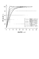
- FIG. 6 is a graph showing measurement results of haze reduction rates in Examples 1 to 3 and Comparative Examples 1 to 3.
- FIG. 1 is a diagram showing an overall configuration of a vehicle lamp 1 to which the present exemplary embodiment is applied.
- the vehicle lamp 1 to which the present embodiment is applied is used as, for example, a head lamp, rear lamp, brake lamp, fog lamp, direction indicator lamp, travel lamp, parking lamp, etc. of various vehicles represented by automobiles.
- FIG. 1 shows an example of these lamps.
- a vehicle lamp 1 shown in FIG. 1 includes a housing 2 that protects vehicle electrical components and the like, and a lens 3 that is attached to the housing 2 and irradiates light at an appropriate angle, such as concentrating light in front of the lamp. And.
- the housing 2 and the lens 3 constitute a closed housing 8 of the vehicle lamp 1, and the waterproofness and dustproofness of each electrical component in the housing 8 are enhanced.
- the inside 8 of the housing is not completely sealed and can be ventilated through the vent opening 9.
- the casing 8 is provided with a bulb 4 that emits light and a reflector 5 that reflects light emitted from the bulb 4 in the lateral direction and rearward toward the front as one of the electrical components.
- the vehicle lamp 1 can facilitate the delivery of air inside and outside the lamp, and in particular, the water vapor in the housing 8 can be quickly released to the outside of the lamp.
- a ventilation member 10 is provided.
- the ventilation member 10 communicates with the ventilation opening 9 to form a bent ventilation path, and functions as a ventilation path support that supports the ventilation path. And the vehicle lamp 1 which has this ventilation member 10 can be grasped
- a projecting portion 2 a for attaching the ventilation member 10 is formed around the ventilation opening 9 of the housing 2.
- the ventilation member 10 can be attached to the housing 2 by fitting the ventilation member 10 into the protruding portion 2a.
- the P direction shown in FIG. 1 is the depth direction, which is the engine room side when the vehicle lamp 1 is used as a headlamp or fog lamp, and the trunk side when the vehicle lamp 1 is used as a rear lamp.
- the water vapor in the housing 8 first proceeds in the first direction (P direction) from the ventilation opening 9 in the ventilation path. Then, it bends in the bending part in the ventilation member 10, and goes to the 2nd direction (Q direction) which is a downward direction from an upper direction in the figure.
- automobile lamps are provided with a hole on the lamp housing (housing) side as a function for escaping water vapor inside the lamp to the outside and a function for eliminating the differential pressure generated by temperature change.
- a dustproof and waterproof ventilation member is attached.
- the compatibility between the function of eliminating the differential pressure and the dust / water resistance can be dealt with by a ventilation member such as a PTFE (polytetrafluoroethylene) film.
- PTFE polytetrafluoroethylene
- the ventilation member can be thinned by installing a single ventilation member in the opening.
- the ventilation member protrudes to the outside as it is, for example, there is a possibility that the ventilation member may be destroyed due to a hydraulic pressure or a stepping stone collision.
- a ventilation device that can be used is provided. That is, a bent ventilation path communicating with the ventilation opening 9 is formed, and this ventilation path has a minimum cross-sectional area that can maintain a fog reduction rate of 80% or more at an elapsed time of 5 minutes. It is configured to maintain up to the final end of the. Further, the bent ventilation path is configured to maintain a minimum cross-sectional area of at least 300 mm 2 up to the final end of the ventilation path including the bent portion.
- the size of the ventilation opening 9 is determined based on sensory indicators such as “good / bad” and “fast / slow” by engineers. It was limited to mention.
- the reference is also limited to “the size of the ventilation opening 9”, and when a bent ventilation path following the ventilation opening 9 is formed, the conventional technique cannot maintain sufficient cloudiness. It was.
- the inventors have found that the cloudy weather characteristics of various lamps having bent ventilation paths are improved by optimizing the indicators of elapsed time and haze reduction rate.
- various lamps with bent ventilation paths have been devised to maintain a predetermined cross-sectional area up to the final end of the bent ventilation path, and proved that the cloudy weather characteristics of various lamps are good. I confirmed.
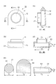
- FIGS. 2A to 2E are views for explaining the ventilation member 10 according to the first embodiment.
- FIG. 2A is a front view of the ventilation member 10 viewed from the attachment side to the ventilation opening 9 shown in FIG. 1
- FIG. 2B is a bottom view of the ventilation member 10 viewed from below with the exhaust port.
- FIG. 2C is a diagram showing a IIC-IIC cross section in the vertical direction (Q direction) of the ventilation member 10 shown in FIG. 2A
- FIG. 2D is a diagram showing FIG. 2A.
- FIG. 6 is a view showing a cross section IID-IID in the horizontal direction (P direction) of the ventilation member 10 shown in FIG.
- FIG. 2 (e) is a diagram for explaining the cross-sectional area / opening area of each part of the ventilation path 20.
- the ventilation member 10 forms a ventilation path 20 constituted by a gap (through hole) as an inner tube, and functions as a ventilation device and a ventilation path support.
- a ventilation device it is possible to define not only the ventilation member 10 but also the housing 2 and the like as “a ventilation device”.
- the ventilation member 10 has an attachment portion 11 for attaching the ventilation member 10 to the ventilation opening 9 (see FIG. 1) and attaching the ventilation member 10 by connecting the ventilation opening 9 and the ventilation path 20.
- the inner pipe used as the ventilation path 20 has a bent portion housing 12 that forms a bent portion bent from the first direction (P direction) to the second direction (Q direction).
- the ventilation member 10 is positioned by the attachment portion 11 and the bent portion housing 12 before the bending that forms the bent portion following the inlet-side ventilation passage 21 and the inlet-side ventilation passage 21 that communicates with the ventilation opening 9.
- a ventilation path 20 is formed between the bent portion inlet side 22 having a wide cross section and the bent portion outlet side 23 located after the bent portion is bent continuously from the bent portion inlet side 22.
- the material of the ventilation member 10 is not limited to a material such as a thermoplastic resin, a thermosetting resin, or a metal. However, from the viewpoint of improving the mounting workability to the housing 2, a thermoplastic elastomer, a thermosetting elastomer, or the like is used. It is preferable to use an elastic body. Further, the shape is preferably formed from one material from the viewpoint of reducing costs, but the shape may be formed by injection molding or two-color molding using materials having different materials and hardness. Furthermore, although the shape and attachment method of the attachment part 11 of the ventilation member 10 follow the structure of the ventilation opening 9 of the housing 2, the circular shape, the quadrangular shape, the elliptical shape, and the like are not limited.
- the ventilation member 10 can be subjected to oil repellent treatment.
- oil repellent treatment include forming an oil repellent film containing a polymer having a perfluoroalkyl group.
- the forming method of the ventilation member 10 is a solution of a polymer having a perfluoroalkyl group by an air spray method, an electrostatic spray method, a dip coat method, a spin coat method, a roll coat method, a curtain flow coat method, an impregnation method, or the like.
- a dispersion coating, an electrodeposition coating method, a film formation method by a plasma polymerization method, or the like can be given.
- the method is not particularly limited as long as a desired film can be formed.
- the cross section of the inlet-side ventilation path 21 (surface perpendicular to the first direction (P direction) on the upstream side of the bent portion) has a circular shape with an inner diameter of T1, and the cross-sectional area is S1.
- the cross section of the bent portion inlet side 22 (the surface orthogonal to the first direction (P direction) on the bent portion inlet side) includes a semicircle having an inner diameter of T2 and a rectangle having a width T2 that is continuous with the semicircle.
- the cross-sectional area is S2.
- the opening surface of the bent portion outlet side 23 (the surface orthogonal to the second direction (Q direction) on the downstream side of the bent portion) is a rectangle having a width T2 and a length T3 in the first direction, and T3 ⁇ T2.
- the cross-sectional area is S3.
- the surface that forms the cross-sectional area S2 of the ventilation member 10 that is the ventilation path support is the surface that forms the cross-sectional area S1 (the cross section of the inlet-side ventilation path 21).
- S2 includes S1.
- the cross-sectional area S2 is a cross section using one side (T2) constituting the cross-sectional area S3.
- This one side (T2) is the length in the direction intersecting the first direction (P direction), and the length is longer than the corresponding length (T1) of the cross-sectional area S1.
- This “intersecting direction” is an “orthogonal direction” in the present embodiment, but when the bending is not a right angle but an obtuse angle or an acute angle, the “intersecting direction” is become.
- the cross-sectional areas S1 and S2 of the ventilation path 20 and the area S3 of the opening are all 300 mm 2 or more. That is, the ventilation member 10 is configured to form a bent ventilation path 20 communicating with the ventilation opening 9 and to maintain a minimum cross-sectional area of at least 300 mm 2 or more up to the final end of the ventilation path including the bent portion. ing. The significance of the cross-sectional area of 300 mm 2 or more will be described later.
- route 20 of the ventilation member 10 connected to the lamp exterior is set to "the function for releasing water vapor
- the area of the ventilation opening 9 provided on the housing 2 side (lamp housing side) or more ” makes the water vapor move smoothly and instantaneously to the outside. Can be released.
- the relationship of each opening area is as follows.
- a through hole is adopted as the ventilation path 20 formed in the ventilation member 10, but is not limited to the through hole. Even if it is a through-hole, it can make it difficult for water and dust from entering from the outside by forming the bent ventilation path 20. Further, by making the cross-sectional area S2 larger than the cross-sectional area S1, T2 can be increased, and in the cross-sectional area S3 determined by T2 ⁇ T3, T3 can be made smaller than T1, and P of the ventilation member 10 can be reduced. The amount of protrusion in the direction can be reduced.
- the length in the second direction of the cross-sectional area S1 or the cross-section constituting the cross-sectional area S1 is 90 ° as the protrusion in the P direction of the bent portion.
- T3 which is a length smaller than the length when rotated is used, an opening cross section of a certain level or more (for example, 300 mm 2 or more) can be maintained, and while maintaining smooth movement of water vapor, P It is possible to provide the ventilation member 10 that is thin in the direction.
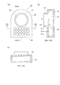
- FIGS. 3A and 3B are views for explaining the ventilation member 30 according to the second embodiment.
- FIG. 3A is a front view of the ventilation member 30 viewed from the attachment side to the ventilation opening 9 shown in FIG. 1
- FIG. 3B is a diagram of the ventilation member 30 shown in FIG. It is the figure which showed the IIIB-IIIB cross section of the up-down direction (Q direction). Note that description of functions, materials, processing, and the like similar to those of the first embodiment is omitted here.
- the ventilation member 30 has an attachment portion 31 that attaches the ventilation member 30 to the ventilation opening 9 and communicates the ventilation opening 9 and the ventilation path 40.
- the inner pipe used as the ventilation path 40 has a bent portion housing 32 that forms a bent portion bent from the first direction (P direction) to the second direction (Q direction).
- the second embodiment is characterized in that it is further bent in the third direction (R direction) from the second direction (Q direction), and the bending in the third direction (R direction) is also a bent portion.
- the casing 32 is formed.
- the ventilation member 30 includes an inlet-side ventilation path 41 that communicates with the ventilation opening 9 shown in FIG. 1 and an inlet-side ventilation path 41 that is positioned before the bending that constitutes the bending section.
- a bent portion inlet side 42 having a wide cross section, a bent portion outlet side 43 positioned after the bent portion is bent continuously to the bent portion inlet side 42, and a discharge port 44 further bent in the R direction.
- a ventilation path 40 is formed.
- the cross section of each part of the ventilation path 40 is the same as that of the first embodiment shown in FIG.
- the cross section of the inlet side ventilation path 41 (surface orthogonal to the first direction (P direction) on the upstream side of the bent portion) has a circular shape with an inner diameter of T1 as in the case of the inlet side ventilation path 21 of the first embodiment. Yes, and the cross-sectional area is S1. Further, the cross section of the bent portion inlet side 42 forming the bent portion (surface orthogonal to the first direction (P direction) on the bent portion inlet side) has an inner diameter similar to that of the bent portion inlet side 22 of the first embodiment.
- the opening surface of the bent portion outlet side 43 (the surface orthogonal to the second direction (Q direction) on the downstream side of the bent portion) has a width T2 similar to the opening surface of the bent portion outlet side 23 of the first embodiment.
- the rectangular shape has a length T3 in the first direction, and the cross-sectional area is S3.
- the area of the discharge port 44 is S3 similar to the area of the opening on the bent portion outlet side 43. In addition, it is also preferable to make the discharge port 44 larger than the cross-sectional area of the opening on the bent portion outlet side 43.
- the cross-sectional areas S1, S2, and S3 of the ventilation path 40 and the area S3 of the opening of the discharge port are all 300 mm 2 or more. That is, the ventilation member 30 is configured to form a bent ventilation path 40 that communicates with the ventilation opening 9 and maintains a minimum cross-sectional area of at least 300 mm 2 or more to the final end of the ventilation path 40 including the bent portion.
- the relationship of the opening areas (cross-sectional area S1 ⁇ cross-sectional area S2, cross-sectional area S1 ⁇ cross-sectional area S3) is the same as that in the first embodiment.
- the point which is a through-hole is the same as that of 1st Embodiment.
- the ventilation member 30 as the ventilation path support has the ventilation path 40 that is further bent in the third direction (R direction) from the second direction (Q direction). Yes.
- the ingress of water and dust from the outside can be reduced more favorably.
- the cross section of 300 mm 2 or more is maintained, even when the number of bent portions is increased, the smooth movement of water vapor from the housing 2 side of the lamp is maintained, and the thickness from the mounting portion is related. It is possible to provide the thin ventilation member 30 in the P direction.
- the direction of the discharge port 44 can be selected relatively freely, it is possible to select the direction of the ventilation path 40 and the like, and the degree of freedom in the overall design of the vehicle lamp 1 can be increased. .
- FIGS. 4A to 4C are views for explaining a ventilation member 50 according to the third embodiment.
- 4A is a front view of the ventilation member 50 viewed from the side of the ventilation opening 9 shown in FIG. 1
- FIG. 4B is a top and bottom view of the ventilation member 50 shown in FIG. 4A. It is the figure which showed IVB-IVB cross section of a direction (Q direction).
- FIG. 4C is a view showing a IVC-IVC cross section in the horizontal direction (P direction) in the ventilation member 50 shown in FIG.
- the third embodiment shown in FIG. 4 is characterized in that the discharge port 44 of the second embodiment shown in FIG. 3 is composed of a plurality of discharge ports.
- the description is abbreviate
- the ventilation member 50 has the attachment part 51 which attaches the ventilation member 50 to the ventilation opening 9, and makes the ventilation opening 9 and the ventilation path 60 communicate.
- the inner pipe used as the ventilation path 60 has a bent portion casing 52 that forms a bent portion bent from the first direction (P direction) to the second direction (Q direction).
- the ventilation path 60 is bent from the second direction (Q direction) to the third direction (R direction).
- the ventilation member 50 includes an inlet-side ventilation path 61 that communicates with the ventilation opening 9 shown in FIG. 1 and a bent part that forms a bent part following the inlet-side ventilation path 61 by the mounting portion 51 and the bent portion housing 52.
- the ventilation path 60 is formed.
- the discharge port 64 includes a plurality of openings. In the example shown in FIG. 4A, there are 18 openings as a whole. However, the number of openings is not limited to the present embodiment. Further, with respect to the direction of the openings, it is not necessary that all the openings are directed in the third direction (R direction), and some of the openings may be directed in the second direction (Q direction). .
- the cross section of each part of the ventilation path 60 is the same as that of the first embodiment and the second embodiment shown in FIG.
- the cross section of the inlet-side ventilation path 61 (surface orthogonal to the first direction (P direction) on the upstream side of the bent portion) is a circular shape having an inner diameter of T1 as in the case of the inlet-side ventilation path 21 of the first embodiment. Yes, and the cross-sectional area is S1.
- the cross section of the bent portion inlet side 42 (a surface orthogonal to the first direction (P direction) on the bent portion inlet side) is a semicircular shape having an inner diameter T2 similar to that of the bent portion inlet side 22 of the first embodiment.
- the opening surface of the bent portion outlet side 63 (the surface orthogonal to the second direction (Q direction) on the downstream side of the bent portion) is the bent portion outlet side of the first embodiment and the second embodiment (23, Similarly to the opening surface of 43), it is a rectangle having a width T2 and a length T3 in the first direction, and its cross-sectional area is S3.
- the area of the discharge port 64 is S3, which is the same as the cross-sectional area of the opening surface of the bent portion outlet side 63, by adding all the areas of the 18 opening holes.
- the area of the discharge port 64 formed by adding the areas of the plurality of opening holes is larger than the cross-sectional area of the bent portion outlet side 63.
- the cross-sectional areas S1, S2, and S3 of the ventilation path 60 are all 300 mm 2 or more. That is, the ventilation member 50 is configured to form a bent ventilation path 60 communicating with the ventilation opening 9 and to maintain a minimum cross-sectional area of at least 300 mm 2 or more up to the final end of the ventilation path 60 including the bent portion.
- the relationship of the opening areas (cross-sectional area S1 ⁇ cross-sectional area S2, cross-sectional area S1 ⁇ cross-sectional area S3) is the same as that in the first and second embodiments.
- the point which is a through-hole is the same as that of 1st Embodiment and 2nd Embodiment.
- a plurality of opening holes are configured as the discharge port 64.
- the sum total of the hole area of this opening hole shall be 300 mm ⁇ 2 > or more.
- a large number of opening holes may be provided at any location in the ventilation path. Even if it is an individual small opening hole, it is possible to secure a total of 300 mm 2 or more in this sum, and it is possible to maintain high cloudiness even when using an opening hole that copes with design requirements, for example. Become.
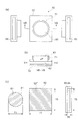
- FIGS. 5A to 5C are views for explaining the ventilation member 70 according to the fourth embodiment.
- FIG. 5A is a front view of the ventilation member 70 viewed from the attachment side to the ventilation opening 9 shown in FIG. 1
- FIG. 5B is a VB of the ventilation member 70 shown in FIG. It is the figure which showed -VB cross section.
- FIG. 5C is a view for explaining cross sections of various portions constituting the ventilation path 80.
- the fourth embodiment shown in FIG. 5 is characterized in that a final discharge port for discharging water vapor is provided in multiple directions, the ventilation path 80 is bent in a plurality of directions, and the ventilation path 80 is branched. is there. Note that the description of matters similar to those in the first to third embodiments is omitted here.
- the ventilation member 70 has the attachment part 71 which attaches the ventilation member 70 to the ventilation opening 9, and makes the ventilation opening 9 and the ventilation path
- the inner pipe used as the ventilation path 80 has a bent portion housing 72 that forms a bent portion bent in a plurality of directions (two directions of V direction and U direction in FIG. 5) from the first direction (P direction). is doing.
- This ventilation member 70 includes an inlet-side ventilation path 81 communicating with the ventilation opening 9 shown in FIG. 1 and a bent part that forms a bent part following the inlet-side ventilation path 81 by the mounting portion 71 and the bent portion casing 72.
- the cross section of the inlet-side ventilation path 81 (a plane orthogonal to the first direction (P direction) on the upstream side of the bent portion) is the same as that of the inlet-side ventilation path 21 of the first embodiment.
- the inner diameter is a circular shape with T1
- the cross-sectional area is S1.
- the cross section of the bent portion entrance side 82 (the surface orthogonal to the first direction (P direction) on the bent portion entrance side) is a square shape having one side of T5 longer than T1, and the cross sectional area is S2 ''. 'Is.
- this S2 "" will be described as S2.
- the opening surface corresponding to the exit side of the bent portion is a surface orthogonal to the U direction and the V direction on the downstream side of the bent portion, that is, the first discharge port 83 and the second discharge port 84, and each is T5 ⁇ . T6.
- T6 the total cross-sectional area which is the total cross-sectional area is S3.
- S3 the same reference numeral as “S3” used in the first to third embodiments is used.
- the length T6 related to the thickness in the depth direction (P direction) can be shortened to 10 mm or less individually because a sufficient cross-sectional area can be secured by the plurality of discharge ports.
- the cross-sectional areas S1 and S2 and the total cross-sectional area S3 of the ventilation path 80 are all 300 mm 2 or more. That is, the ventilation member 70 is configured to form a bent ventilation path communicating with the ventilation opening 9 and to maintain a minimum cross-sectional area of at least 300 mm 2 up to the final end of the ventilation path including the bent portion. Yes. Further, the relationship of the opening areas (cross-sectional area S1 ⁇ cross-sectional area S2, cross-sectional area S1 ⁇ cross-sectional area S3) is the same as in the first to third embodiments. The point of being a through hole is the same as in the first to third embodiments.
- the 1st discharge port 83 and the 2nd discharge port 84 were provided as a some discharge port, and the some opening hole was comprised. And the sum total of the hole area of this some opening hole shall be 300 mm ⁇ 2 > or more.
- T5 one side of the bent portion inlet side 82 that forms the bent portion of the ventilation member 70
- the final end discharge port is formed, and further, a plurality of such discharge ports are provided, thereby providing a depth direction. Even when the length in the first direction and the P direction is shorter than the length in the first direction when the cross section constituting the cross-sectional area S1 is rotated by 90 °, good cloudiness Can be maintained.
- the ventilation member 10 (30, 50, 70) of the present invention will be described in more detail using examples.
- the present invention is not limited to the following examples.
- Example 1 Humidity adjustment and water injection were performed on the vehicle lamp 1 having the ventilation opening 9 as described below, and then a ventilation member 10 was attached to the ventilation opening 9 to measure the fog reduction rate.
- a tubular vent member 10 having a bent portion, an inner diameter of 40 mm, and a cross-sectional area of the vent path 20 of 1257 mm 2 was used as the vent member 10.
- the ventilation member 10 used in this example has a cross-sectional area of 1257 mm 2 from one end of the ventilation path to the other end of the ventilation path including the bent portion.
- As the vehicle lamp 1 a medium-sized vehicle headlamp (2011 Genesis Coupe HL manufactured by Hyundai Mobis Co., Ltd.) having an internal volume of 6900 cc was used.
- the vehicular lamp 1 having the ventilation opening 9 was left for 2 hours under high temperature drying conditions (temperature: 80 ⁇ 2 ° C., relative humidity (RH): 10%). Subsequently, the vehicle lamp 1 is kept at room temperature and normal pressure (temperature: 15 ° C. to 35 ° C., RH: 45% to 75%) with the ventilation opening 9 and the like kept open (without the ventilation member 10 attached). And left for 1 hour. Thereafter, the vehicle lamp 1 was left under humidity control conditions (temperature: 38 ° C., RH: 70%) for 1 hour while the ventilation opening 9 was left open, and the humidity in the housing 8 of the vehicle lamp 1 was adjusted. .
- RH relative humidity
- a ventilation member 10 was attached to the ventilation opening 9 of the vehicular lamp 1 immediately after the humidity control.
- the vehicle lamp 1 was turned on for 20 minutes and then turned off. Thereafter, using a hose with an inner diameter of 19 mm, water was poured into the vehicle lamp 1 in the extinguished state from the front side of the lens 3 for 3 minutes.
- Water having a water temperature of 10 ⁇ 2 ° C. was used, and the water pressure was set to 100 ⁇ 20 kPa.
- the tip of the hose is 10 cm away from the lens 3 of the vehicle lamp 1 and the water injection angle is changed from the vertical direction (90 ° upward with respect to the horizontal direction) to 30 ° upward with respect to the horizontal direction. The water was poured.
- the fogging reduction rate of the lens 3 was measured.
- the “fogging reduction rate (%)” represents the amount of defogging of the lens 3 after a predetermined time has elapsed after the vehicle lamp 1 has been lit for 10 minutes.
- the cloudy state of the lens 3 at the time when the vehicle lamp 1 is lit for 10 minutes is defined as a fog reduction rate 0%.
- the fog reduction rate of 50% indicates a state in which the fog of the lens 3 has been eliminated by half compared to the time when the vehicle lamp 1 is lit for 10 minutes (elapsed time 0 minutes).
- a haze reduction rate of 100% indicates a state in which all the fogging of the lens 3 has been eliminated (a state in which the lens 3 is not fogged at all).
- a lamp such as the vehicle lamp 1 can be used without worrying about the influence of fogging of the lens 3 when the fog reduction rate is 80% or more.
- the fog reduction rate was measured visually by observing the lens 3 of the vehicle lamp 1 from the front side (outside of the vehicle lamp 1) every predetermined time.
- the haze reduction rate may be calculated by, for example, photographing the lens 3 every predetermined time and processing the photographed image.
- Example 2 The haze reduction rate of the lens 3 in the vehicle lamp 1 is measured in the same manner as in Example 1 except that the inner diameter of the ventilation member 10 attached to the ventilation opening 9 of the vehicle lamp 1 and the cross-sectional area of the ventilation path are different. went.
- Example 2 a tubular ventilation member 10 having an inner diameter of 30 mm and a sectional area of 707 mm 2 is used, and in Example 3, a tubular ventilation member 10 having an inner diameter of 20 mm and a sectional area of 314 mm 2 is used. It was.
- Comparative Example 1 a tube-shaped ventilation member 10 having an inner diameter of 15 mm and a cross-sectional area of 177 mm 2 was used.
- Comparative Example 2 a tube-shaped ventilation member 10 having an inner diameter of 10 mm and a cross-sectional area of 79 mm 2 was used. .
- the fog reduction rate of the lens 3 in the vehicular lamp 1 is the same as that of the first embodiment except that the vehicular lamp 1 is provided with three vent openings 9 and the vent members 10 attached to the vent openings 9 are different.
- Each ventilation member 10 to be attached to the ventilation opening 9 has a bent portion, a tubular shape having an inner diameter of 8.5 mm and a cross-sectional area of 57 mm 2 , and is made of rubber in which a porous sponge is packed in the ventilation path.
- the ventilation member 10 was used.
- the total cross-sectional area of the three ventilation members 10 is 171 mm 2 .
- FIG. 6 is a diagram showing the measurement results of the haze reduction rate of Examples 1 to 3 and Comparative Examples 1 to 3, more specifically, Examples 1 to 3 and Comparative Example 1.
- FIG. 5 is a graph showing a change over time in the haze reduction rate measured in Comparative Example 3.
- the fog reduction rate of the lens 3 is 80% or more within an elapsed time of 5 minutes. That is, in the vehicular lamp 1 using the ventilation member 10 according to the first to third embodiments, even when the lens 3 is clouded, the use is not affected in a short time of 5 minutes or less. It was confirmed that cloudiness could be eliminated. On the other hand, in Comparative Examples 1 to 3, it takes more than 5 minutes to make the haze reduction rate of the lens 3 80% or higher. Compared with Examples 1 to 3. It was confirmed that it takes a long time to eliminate the fogging of the lens 3. This elapsed time of 5 minutes is a time derived by the inventors as a judgment criterion that causes a problem as a lamp used for a vehicle.
- the increase rate of the haze reduction rate at the early stage of the elapsed time (for example, the elapsed time is within 3 minutes) (that is, 6 is significantly larger than those of Comparative Examples 1 to 3. That is, the ventilation member 10 is configured to maintain a minimum cross-sectional area of at least 300 mm 2 or more up to the final end including the bent portion, so that the minimum cross-sectional area of the ventilation path is less than 300 mm 2. It was confirmed that the fogging of the lens 3 can be quickly eliminated.
- Example 1 and Example 2 could achieve a haze reduction rate of 80% or more in a shorter time than Example 3.
- the haze reduction rate may hardly change even though Example 1 is larger in cross-sectional area of the ventilation path 20 than Example 2. confirmed. Therefore, in order to obtain good cloudiness while suppressing the entry of foreign matter or the like into the housing 8 of the vehicle lamp 1 via the ventilation member 10 and suppressing the enlargement of the ventilation member 10, the ventilation member It was confirmed that the minimum cross-sectional area of 10 is more preferably about 700 mm 2 .
- Example 2 Although illustration is omitted, humidity control and water injection were performed in the same manner as in Example 1 except that the ventilation member 10 having an inner diameter of 60 mm and a cross-sectional area of 2826 mm 2 was used, and the vehicle lamp 1 was lit for 10 minutes. In this case, it was confirmed that the lens 3 was not fogged (the fog reduction rate was 100% at an elapsed time of 0 minutes).
- the tubular ventilation member 10 having a bent portion is used.
- the minimum cross-sectional area of the ventilation path 20 (the total of the minimum cross-sectional areas of the plurality of ventilation paths when the ventilation path is branched) is at least 300 mm 2 .
- fogging of various lamps having bent ventilation paths (20, 40, 60, 80) is achieved by optimizing the indicators of elapsed time and fog reduction rate. It was possible to improve the sunny characteristics.
- the haze reduction rate is 80% or more at an elapsed time of 5 minutes. Then, by keeping the minimum cross-sectional area capable of maintaining this index up to the final end of the ventilation path (20, 40, 60, 80) including the bent portion, the bent ventilation path (20, Even when 40, 60, 80) is formed, excellent cloudiness can be achieved.
- various lamps having a bent ventilation path (20, 40, 60, 80) are predetermined to the final end of the bent ventilation path (20, 40, 60, 80).
- the vehicular lamp 1 has good cloudy weather characteristics.
- the minimum cross-sectional area of 300 mm 2 or more is maintained as the predetermined cross-sectional area up to the final end of the ventilation path (20, 40, 60, 80) including the bent portion.
- improvement in quality for various lamps has been screamed, and further improvement in cloudiness is required.
- the sectional area of the opening is 300 mm 2 or more. Is meaningful.
- a tube structure having a circular cross section of 300 mm 2 or more has a diameter of about 20 mm.
- this tube structure is bent as it is, it becomes larger than 20 mm only by protruding the bent portion.
- an engine room is present on the depth side of the vehicle lamp 1 and various devices such as an electronic control unit (ECU) are gathered. It is not preferable to project the tube structure as it is because of space problems. . According to this embodiment, it is possible to bend at a narrow portion while maintaining a sufficient cross-sectional area in the entire ventilation path (20, 40, 60, 80).
- SYMBOLS 1 Vehicle lamp, 2 ... Housing, 3 ... Lens, 8 ... Inside housing, 9 ... Vent opening, 10, 30, 50, 70 ... Ventilation member, 20, 40, 60, 80 ... Ventilation path
Landscapes
- Engineering & Computer Science (AREA)
- General Engineering & Computer Science (AREA)
- Mechanical Engineering (AREA)
- Arrangement Of Elements, Cooling, Sealing, Or The Like Of Lighting Devices (AREA)
- Non-Portable Lighting Devices Or Systems Thereof (AREA)
Abstract
Description
また、前記通気経路支持体の前記通気経路(20、40、60)は、第1方向(P)から第2方向(Q)に屈曲する屈曲部を有するとともに、当該通気経路の断面積の総和を300mm2以上に維持しながら当該屈曲部における当該第1方向への突出量を当該通気開口(9)の開口幅よりも小さくしたことを特徴としている。
〔車両用ランプの全体構成〕
図1は、本実施の形態が適用される車両用ランプ1の全体構成を示した図である。
本実施の形態が適用される車両用ランプ1は、例えば自動車用に代表される各種車両のヘッドランプ、リアランプ、ブレーキランプ、フォグランプ、方向指示ランプ、走行ランプ、駐車ランプ等として用いられる。図1は、これらランプ類の一例を示している。
ここで、特許文献1(特許第4276246号公報)に開示された通気装置では、通気開口面積の合計が132mm2以上とされ、結露解消のための水蒸気透過性には一定の機能を果たしている。しかし、耐防塵、耐防水を確保するために、この文献のように開口部へ通気部材としてPTFE膜を設置すると、通気材を取り付けない貫通穴に比べて透過性が劣ることから、この文献に示される132mm2程度の開口では、近年の曇り晴れ性に対する高い要求に応えられない。また、通気部材単品を開口部に設置することで薄型化を図れるが、例えば外部にそのまま突出させた場合には、水圧や飛び石の衝突などにより、通気材が破壊される可能性がある。
従前では、車両用ランプ1の筐体内8の水蒸気の排出量を把握するに際し、技術者らによる「良い/悪い」、「早い/遅い」といった感覚的な指標に基づき通気開口9の大きさに言及する程度に留まっていた。また、その言及も「通気開口9の大きさ」に留まっており、通気開口9に続く屈曲した通気経路を形成した場合には、従前の技術では十分な曇り晴れ性を維持することができなかった。
発明者等は、経過時間と曇り減少率という指標を適正化することにより、屈曲した通気経路を有する各種ランプの曇り晴れ特性が良好となることを見いだした。また、屈曲した通気経路を有する各種ランプにて、屈曲した通気経路の最終端まで、予め定められた断面積を維持することを考案し、各種ランプの曇り晴れ特性が良好となることを実証により確かめた。
図2(a)~(e)は、第1の実施形態である通気部材10を説明するための図である。ここで図2(a)は図1に示す通気開口9側への取付側から通気部材10を眺めた正面図、図2(b)は排気口のある下方向から通気部材10を眺めた下面図である。また、図2(c)は、図2(a)に示す通気部材10における図の上下方向(Q方向)のIIC-IIC断面を示した図、図2(d)は、図2(a)に示す通気部材10における図の水平方向(P方向)のIID-IID断面を示した図である。さらに、図2(e)は、通気経路20の各箇所の断面積・開口面積を説明するための図である。
断面積S1<断面積S2
断面積S1≦断面積S3
すなわち、水蒸気の円滑移動を維持するためには、通気経路20として一定以上の開口面積を最終端まで維持する必要があるが、通気経路20を断面積S1のまま屈曲させた場合(断面積S1を構成する断面を90°回転させた場合)では、第1方向(P方向)の突出が断面積S1の第2方向の長さとなり(すなわち第1方向(P方向)の突出が長さT1となり)、突出量が大きくなってしまう。特に近年、ランプの曇り晴れ特性の更なる向上が要求されており、その結果、通気開口9の面積が大きくなり、通気部材10の通気経路20の開口面積も大きくすることが必要となった。その一方で、装置の小型化も強く要求されていた。そこで、本実施の形態では、屈曲部で幅広のT2を採用することで、屈曲部のP方向の突出として、断面積S1の第2方向の長さまたは断面積S1を構成する断面を90°回転させた場合の長さに比べて小さな長さであるT3を採用しても、一定以上(例えば300mm2以上)の開口断面を維持することができ、水蒸気の円滑移動を維持したまま、P方向に薄型の通気部材10を提供することが可能となった。
次に、通気部材の第2の実施形態について説明する。
図3(a)(b)は、第2の実施形態である通気部材30を説明するための図である。ここで図3(a)は、図1に示す通気開口9側への取付側から通気部材30を眺めた正面図、図3(b)は、図3(a)に示す通気部材30における図の上下方向(Q方向)のIIIB-IIIB断面を示した図である。尚、第1の実施形態と同様な機能、材料や処理などについては、ここでは、その説明を省略する。
この通気部材30は、取付部31と屈曲部筐体32とにより、図1に示す通気開口9に連通する入口側通気経路41と、屈曲部を構成する曲がり前に位置し入口側通気経路41に続いて幅広の断面を有する屈曲部入口側42と、屈曲部入口側42に連続して屈曲部の曲がり後に位置する屈曲部出口側43と、さらにR方向に屈曲する排出口44と、の通気経路40を形成している。
次に、通気部材の第3の実施形態について説明する。
図4(a)~(c)は、第3の実施形態である通気部材50を説明するための図である。
ここで図4(a)は、図1に示す通気開口9側への取付側から通気部材50を眺めた正面図、図4(b)は、図4(a)に示す通気部材50の上下方向(Q方向)のIVB-IVB断面を示した図である。図4(c)は、図4(a)に示す通気部材50における水平方向(P方向)のIVC-IVC断面を示した図である。
図4に示す第3の実施形態は、図3に示す第2の実施形態の排出口44を、複数の排出口で構成した点に特徴がある。尚、第1の実施形態、第2の実施形態と同様な事項については、ここでは、その説明を省略する。
次に、通気部材の第4の実施形態について説明する。
図5(a)~(c)は、第4の実施形態である通気部材70を説明するための図である。
ここで図5(a)は、図1に示す通気開口9側への取付側から通気部材70を眺めた正面図、図5(b)は、図5(a)に示す通気部材70のVB-VB断面を示した図である。また、図5(c)は、通気経路80を構成する各所の断面を説明するための図である。
図5に示す第4の実施形態は、水蒸気を排出させる際の最終となる排出口を多方向に設け、通気経路80を複数方向に屈曲させ、通気経路80を分岐させている点に特徴がある。尚、第1~第3の実施形態と同様な事項については、ここでは、その説明を省略する。
〔実施例1〕
通気開口9を有する車両用ランプ1に対して、以下に説明するように調湿および注水を行った後、通気開口9に通気部材10を取り付け、曇り減少率の測定を行った。
この例では、通気部材10として、屈曲部を有し、内径が40mm、通気経路20の断面積が1257mm2の管形状の通気部材10を用いた。言い換えると、この例で用いた通気部材10は、通気経路の一端から、屈曲部を含め通気経路の他端まで、断面積が1257mm2となっている。
また、車両用ランプ1としては、内部容積が6900ccの中型車用ヘッドランプ(現代モービス社製2011年式ジェネシス・クーペHL)を用いた。
通気開口9を有する車両用ランプ1を、高温乾燥条件(温度:80±2℃、相対湿度(RH):10%)で2時間放置した。続いて、通気開口9等を開放状態としたまま(通気部材10を取り付けない状態で)、車両用ランプ1を常温常圧条件(温度:15℃~35℃、RH:45%~75%)で1時間放置した。その後、通気開口9を開放状態としたまま、車両用ランプ1を調湿条件(温度:38℃、RH:70%)で1時間放置し、車両用ランプ1の筐体内8の湿度を調整した。
上記調湿を行った直後の車両用ランプ1の通気開口9に対し、通気部材10を取り付けた。そして、車両用ランプ1を20分間点灯した後、消灯した。
その後、内径が19mmのホースを使用して、消灯した状態の車両用ランプ1に、レンズ3の正面側から3分間注水した。なお、水は水温10±2℃のものを用い、水圧は100±20kPaとなるようにした。また、ホースの先は、車両用ランプ1のレンズ3から10cm離れた状態とし、注水角度を、鉛直方向(水平方向に対して上方に90°)~水平方向に対して上方へ30°まで変えながら注水を行った。
続いて、車両用ランプ1を10分間点灯した後、車両用ランプ1を点灯した状態で、レンズ3の曇りが晴れるまでの様子を観察し、レンズ3の曇り減少率を測定した。
なお、この例において「曇り減少率(%)」とは、車両用ランプ1を10分間点灯した後、所定時間経過後のレンズ3の曇りの解消量を表すものである。この場合、車両用ランプ1を10分間点灯した時点(経過時間0分)でのレンズ3の曇りの状態を曇り減少率0%とする。例えば、曇り減少率が50%とは、車両用ランプ1を10分間点灯した時点(経過時間0分)と比べて、レンズ3の曇りが半分解消した状態を示す。また、曇り減少率が100%とは、レンズ3の曇りが全て解消した状態(レンズ3に全く曇りが生じていない状態)を示す。
通常、車両用ランプ1等のランプでは、曇り減少率が80%以上の場合に、レンズ3の曇りの影響を気にすることなく使用することができる。
なお、曇り減少率は、目視による測定のほか、例えばレンズ3を所定時間毎に撮影し、撮影した画像を画像処理することにより算出してもよい。
車両用ランプ1の通気開口9に取り付ける通気部材10の内径および通気経路の断面積を異ならせた以外は、実施例1と同様にして、車両用ランプ1におけるレンズ3の曇り減少率の測定を行った。
ここで、実施例2では、内径が30mm、断面積が707mm2の管形状の通気部材10を用い、実施例3では、内径が20mm、断面積が314mm2の管形状の通気部材10を用いた。また、比較例1では、内径が15mm、断面積が177mm2の管形状の通気部材10を用い、比較例2では、内径が10mm、断面積が79mm2の管形状の通気部材10を用いた。
車両用ランプ1に通気開口9を3つ設けるとともに、それぞれの通気開口9に取り付ける通気部材10を異ならせた以外は、実施例1と同様にして、車両用ランプ1におけるレンズ3の曇り減少率の測定を行った。
通気開口9に取り付けるそれぞれの通気部材10としては、屈曲部を有し、内径が8.5mm、断面積が57mm2の管形状であり、通気経路に多孔質のスポンジが詰められたゴム製の通気部材10を用いた。なお、比較例3では、3つの通気部材10の断面積の合計が171mm2となっている。
図6は、実施例1~実施例3および比較例1~比較例3の曇り減少率の測定結果を示した図であり、より具体的には、実施例1~実施例3および比較例1~比較例3にて測定した曇り減少率の時間変化を示した図である。
すなわち、実施例1~実施例3の通気部材10を用いた車両用ランプ1では、レンズ3に曇りが生じた場合であっても、5分以内という短い時間で、使用に影響がない程度に曇りを解消できることが確認された。
これに対し、比較例1~比較例3では、レンズ3の曇り減少率を80%以上とするためには5分を超える時間を要しており、実施例1~実施例3と比較して、レンズ3の曇りを解消するために長い時間を要することが確認された。
この経過時間の5分は、車両用に用いられるランプとして支障の出る判断基準として発明者等が導き出した時間である。
すなわち、通気部材10は、少なくとも300mm2以上の最小断面積を、屈曲部を含め最終端まで維持するように構成されることで、通気経路の最小断面積が300mm2未満の場合と比較して、レンズ3の曇りを迅速に解消できることが確認された。
したがって、通気部材10を介して車両用ランプ1の筐体内8へ異物等の侵入を抑制し、また通気部材10の大型化を抑制しながら、良好な曇り晴れ性を得るためには、通気部材10の最小断面積を700mm2程度とすることがより好ましいことが確認された。
Claims (6)
- 車両用ランプの筐体内の水蒸気を当該筐体の外部へ排出させるための通気装置であって、
前記筐体の通気開口に連通して屈曲した通気経路を形成するとともに、当該通気経路が、経過時間5分で曇り減少率が80%以上を維持可能な最小断面積を、屈曲部を含め通気経路の最終端まで維持するように構成された通気経路支持体
を有する通気装置。 - 前記通気経路の前記最小断面積の合計は、少なくとも300mm2以上であり、300mm2以上の最小断面積を最終端まで維持したことを特徴とする請求項1記載の通気装置。
- 前記通気経路支持体の前記通気経路は、第1方向から第2方向に屈曲する屈曲部を有するとともに、当該通気経路の断面積の総和を300mm2以上に維持しながら当該屈曲部における当該第1方向への突出量を当該通気開口の開口幅よりも小さくしたことを特徴とする請求項2記載の通気装置。
- 車両用ランプの筐体内の水蒸気を当該筐体の外部へ排出させるための通気装置であって、
前記筐体の通気開口に連通して屈曲した通気経路を形成するとともに、当該通気経路が、少なくとも300mm2以上の最小断面積を屈曲部を含め通気経路の最終端まで維持するように構成された通気経路支持体
を有する通気装置。 - 前記通気経路支持体の前記通気経路は、複数の通気経路に分岐する分岐部を有し、分岐後の複数の経路の最小断面積の合計は300mm2以上であり、合計が300mm2以上の最小断面積を、分岐部から通気経路の最終端まで維持するように当該通気経路が構成されたことを特徴とする請求項4記載の通気装置。
- 光を出射する電装部品と、
前記電装部品を含め内部に空間を形成する筐体と、
前記筐体に設けられ、当該筐体内の水蒸気を排出する通気開口と、
前記筐体の通気開口に連通して屈曲した通気経路を形成する通気経路支持体と、を備え、
前記通気経路支持体の前記通気経路は、経過時間5分で曇り減少率が80%以上を維持可能な最小断面積を屈曲部を含め通気経路の最終端まで維持するように構成されたこと、または、少なくとも300mm2以上の最小断面積を屈曲部を含め通気経路の最終端まで維持するように構成されたこと
を特徴とする車両用ランプ。
Priority Applications (4)
| Application Number | Priority Date | Filing Date | Title |
|---|---|---|---|
| CN201480078175.2A CN106461176A (zh) | 2014-04-23 | 2014-12-25 | 通气装置及车辆用灯 |
| US15/306,317 US9885456B2 (en) | 2014-04-23 | 2014-12-25 | Ventilation device and vehicular lamp |
| KR1020167029076A KR20160138148A (ko) | 2014-04-23 | 2014-12-25 | 통기 장치 및 차량용 램프 |
| EP14889884.4A EP3135985A4 (en) | 2014-04-23 | 2014-12-25 | Ventilation device and vehicular lamp |
Applications Claiming Priority (2)
| Application Number | Priority Date | Filing Date | Title |
|---|---|---|---|
| JP2014-089227 | 2014-04-23 | ||
| JP2014089227A JP2015207529A (ja) | 2014-04-23 | 2014-04-23 | 通気装置、および車両用ランプ |
Publications (1)
| Publication Number | Publication Date |
|---|---|
| WO2015162829A1 true WO2015162829A1 (ja) | 2015-10-29 |
Family
ID=54332013
Family Applications (1)
| Application Number | Title | Priority Date | Filing Date |
|---|---|---|---|
| PCT/JP2014/084257 Ceased WO2015162829A1 (ja) | 2014-04-23 | 2014-12-25 | 通気装置、および車両用ランプ |
Country Status (6)
| Country | Link |
|---|---|
| US (1) | US9885456B2 (ja) |
| EP (1) | EP3135985A4 (ja) |
| JP (1) | JP2015207529A (ja) |
| KR (1) | KR20160138148A (ja) |
| CN (1) | CN106461176A (ja) |
| WO (1) | WO2015162829A1 (ja) |
Cited By (1)
| Publication number | Priority date | Publication date | Assignee | Title |
|---|---|---|---|---|
| CN107084350A (zh) * | 2016-02-12 | 2017-08-22 | 现代摩比斯株式会社 | 主动灯除湿器及其除湿方法 |
Families Citing this family (1)
| Publication number | Priority date | Publication date | Assignee | Title |
|---|---|---|---|---|
| US10746373B2 (en) * | 2016-10-06 | 2020-08-18 | Flex-N-Gate Advanced Product Development, Llc | Condensation collection device |
Citations (2)
| Publication number | Priority date | Publication date | Assignee | Title |
|---|---|---|---|---|
| JPS6084003U (ja) * | 1983-10-21 | 1985-06-10 | 市光工業株式会社 | 車輌用灯具 |
| JPH042409U (ja) * | 1990-04-20 | 1992-01-10 |
Family Cites Families (9)
| Publication number | Priority date | Publication date | Assignee | Title |
|---|---|---|---|---|
| JPH067522Y2 (ja) | 1986-11-19 | 1994-02-23 | 株式会社小糸製作所 | 自動車用灯具 |
| JP3218943B2 (ja) * | 1995-10-17 | 2001-10-15 | 市光工業株式会社 | 車両用灯具 |
| US6210014B1 (en) | 1997-01-21 | 2001-04-03 | Gore Enterprise Holdings, Inc. | System for reducing condensation in enclosed lamp housings |
| JP2003336874A (ja) | 2002-05-15 | 2003-11-28 | Nitto Denko Corp | 通気部材およびこれを用いた通気筐体 |
| JP4855203B2 (ja) | 2005-12-14 | 2012-01-18 | 日東電工株式会社 | 通気部材および通気構造 |
| US20100227544A1 (en) | 2005-12-14 | 2010-09-09 | Nitto Denko Corporation | Vent Member and Vent Structure |
| JP4953663B2 (ja) * | 2006-03-02 | 2012-06-13 | 日東電工株式会社 | 通気部材および通気構造 |
| JP5030285B2 (ja) * | 2007-09-27 | 2012-09-19 | スタンレー電気株式会社 | 車両用灯具 |
| FR2950674B1 (fr) * | 2009-09-30 | 2012-08-31 | Valeo Vision | Dispositif d'eclairage et/ou de signalisation pour vehicule automobile |
-
2014
- 2014-04-23 JP JP2014089227A patent/JP2015207529A/ja active Pending
- 2014-12-25 WO PCT/JP2014/084257 patent/WO2015162829A1/ja not_active Ceased
- 2014-12-25 US US15/306,317 patent/US9885456B2/en not_active Expired - Fee Related
- 2014-12-25 CN CN201480078175.2A patent/CN106461176A/zh active Pending
- 2014-12-25 KR KR1020167029076A patent/KR20160138148A/ko not_active Ceased
- 2014-12-25 EP EP14889884.4A patent/EP3135985A4/en not_active Withdrawn
Patent Citations (2)
| Publication number | Priority date | Publication date | Assignee | Title |
|---|---|---|---|---|
| JPS6084003U (ja) * | 1983-10-21 | 1985-06-10 | 市光工業株式会社 | 車輌用灯具 |
| JPH042409U (ja) * | 1990-04-20 | 1992-01-10 |
Non-Patent Citations (1)
| Title |
|---|
| See also references of EP3135985A4 * |
Cited By (2)
| Publication number | Priority date | Publication date | Assignee | Title |
|---|---|---|---|---|
| CN107084350A (zh) * | 2016-02-12 | 2017-08-22 | 现代摩比斯株式会社 | 主动灯除湿器及其除湿方法 |
| CN107084350B (zh) * | 2016-02-12 | 2019-09-17 | 现代摩比斯株式会社 | 主动灯除湿器及其除湿方法 |
Also Published As
| Publication number | Publication date |
|---|---|
| US9885456B2 (en) | 2018-02-06 |
| JP2015207529A (ja) | 2015-11-19 |
| CN106461176A (zh) | 2017-02-22 |
| KR20160138148A (ko) | 2016-12-02 |
| US20170045195A1 (en) | 2017-02-16 |
| EP3135985A1 (en) | 2017-03-01 |
| EP3135985A4 (en) | 2018-01-03 |
Similar Documents
| Publication | Publication Date | Title |
|---|---|---|
| US10106155B2 (en) | Vehicular camera with on-board microcontroller | |
| EP1365191B1 (en) | Anti-fogging structure for vehicle headlights | |
| CN105814359B (zh) | 车辆用灯具 | |
| JP2020075706A5 (ja) | ||
| WO2015162829A1 (ja) | 通気装置、および車両用ランプ | |
| CN105546444A (zh) | 用于机动车的照明设备 | |
| WO2015162830A1 (ja) | 通気装置、および車両用ランプ | |
| CN206207257U (zh) | 车辆的灯模块的通风装置 | |
| CN109156086B (zh) | 用于车辆内的电子部件的壳体 | |
| CN206130790U (zh) | 用于车辆的灯模块的通风装置 | |
| JP5030285B2 (ja) | 車両用灯具 | |
| CN106494308B (zh) | 外部后视镜装置 | |
| CN106461177A (zh) | 通气部件及通气装置 | |
| CN117028901A (zh) | 一种汽车灯具防雾结构、一种灯具及汽车 | |
| CN108473079B (zh) | 机动车辆的发光信号装置 | |
| CN106152014B (zh) | 具有包括围绕灯座的凸起部和排水开口的壳体的车辆光学单元 | |
| WO2015145970A1 (ja) | 車両用ランプ | |
| JP2016081892A (ja) | 車両用灯具の換気構造 | |
| CN110017457A (zh) | 用于机动车灯的通风系统 | |
| US12584607B2 (en) | Illumination unit having an antifogging system | |
| KR20180098980A (ko) | 차량용 램프 | |
| CN210511476U (zh) | 发光装置和车辆 | |
| JP7607814B1 (ja) | 車載機器の通気構造 | |
| JP7824974B2 (ja) | 光学装置 | |
| US8550679B2 (en) | Ventilated reflector housing for motor vehicle lamp |
Legal Events
| Date | Code | Title | Description |
|---|---|---|---|
| 121 | Ep: the epo has been informed by wipo that ep was designated in this application |
Ref document number: 14889884 Country of ref document: EP Kind code of ref document: A1 |
|
| ENP | Entry into the national phase |
Ref document number: 20167029076 Country of ref document: KR Kind code of ref document: A |
|
| REEP | Request for entry into the european phase |
Ref document number: 2014889884 Country of ref document: EP |
|
| WWE | Wipo information: entry into national phase |
Ref document number: 2014889884 Country of ref document: EP |
|
| NENP | Non-entry into the national phase |
Ref country code: DE |
|
| WWE | Wipo information: entry into national phase |
Ref document number: 15306317 Country of ref document: US |