WO2015162843A1 - 情報処理装置、情報処理方法、プログラム、調整装置、及び画像表示システム - Google Patents
情報処理装置、情報処理方法、プログラム、調整装置、及び画像表示システム Download PDFInfo
- Publication number
- WO2015162843A1 WO2015162843A1 PCT/JP2015/001227 JP2015001227W WO2015162843A1 WO 2015162843 A1 WO2015162843 A1 WO 2015162843A1 JP 2015001227 W JP2015001227 W JP 2015001227W WO 2015162843 A1 WO2015162843 A1 WO 2015162843A1
- Authority
- WO
- WIPO (PCT)
- Prior art keywords
- projection
- image
- adjustment
- pixels
- boundary
- Prior art date
- Legal status (The legal status is an assumption and is not a legal conclusion. Google has not performed a legal analysis and makes no representation as to the accuracy of the status listed.)
- Ceased
Links
Images


Classifications
-
- H—ELECTRICITY
- H04—ELECTRIC COMMUNICATION TECHNIQUE
- H04N—PICTORIAL COMMUNICATION, e.g. TELEVISION
- H04N9/00—Details of colour television systems
- H04N9/12—Picture reproducers
- H04N9/31—Projection devices for colour picture display, e.g. using electronic spatial light modulators [ESLM]
- H04N9/3179—Video signal processing therefor
- H04N9/3185—Geometric adjustment, e.g. keystone or convergence
-
- G—PHYSICS
- G09—EDUCATION; CRYPTOGRAPHY; DISPLAY; ADVERTISING; SEALS
- G09G—ARRANGEMENTS OR CIRCUITS FOR CONTROL OF INDICATING DEVICES USING STATIC MEANS TO PRESENT VARIABLE INFORMATION
- G09G5/00—Control arrangements or circuits for visual indicators common to cathode-ray tube indicators and other visual indicators
- G09G5/36—Control arrangements or circuits for visual indicators common to cathode-ray tube indicators and other visual indicators characterised by the display of a graphic pattern, e.g. using an all-points-addressable [APA] memory
- G09G5/38—Control arrangements or circuits for visual indicators common to cathode-ray tube indicators and other visual indicators characterised by the display of a graphic pattern, e.g. using an all-points-addressable [APA] memory with means for controlling the display position
-
- H—ELECTRICITY
- H04—ELECTRIC COMMUNICATION TECHNIQUE
- H04N—PICTORIAL COMMUNICATION, e.g. TELEVISION
- H04N17/00—Diagnosis, testing or measuring for television systems or their details
-
- H—ELECTRICITY
- H04—ELECTRIC COMMUNICATION TECHNIQUE
- H04N—PICTORIAL COMMUNICATION, e.g. TELEVISION
- H04N9/00—Details of colour television systems
- H04N9/12—Picture reproducers
- H04N9/31—Projection devices for colour picture display, e.g. using electronic spatial light modulators [ESLM]
- H04N9/3141—Constructional details thereof
- H04N9/3147—Multi-projection systems
-
- H—ELECTRICITY
- H04—ELECTRIC COMMUNICATION TECHNIQUE
- H04N—PICTORIAL COMMUNICATION, e.g. TELEVISION
- H04N9/00—Details of colour television systems
- H04N9/12—Picture reproducers
- H04N9/31—Projection devices for colour picture display, e.g. using electronic spatial light modulators [ESLM]
- H04N9/3191—Testing thereof
-
- G—PHYSICS
- G09—EDUCATION; CRYPTOGRAPHY; DISPLAY; ADVERTISING; SEALS
- G09G—ARRANGEMENTS OR CIRCUITS FOR CONTROL OF INDICATING DEVICES USING STATIC MEANS TO PRESENT VARIABLE INFORMATION
- G09G2340/00—Aspects of display data processing
- G09G2340/04—Changes in size, position or resolution of an image
- G09G2340/0464—Positioning
-
- G—PHYSICS
- G09—EDUCATION; CRYPTOGRAPHY; DISPLAY; ADVERTISING; SEALS
- G09G—ARRANGEMENTS OR CIRCUITS FOR CONTROL OF INDICATING DEVICES USING STATIC MEANS TO PRESENT VARIABLE INFORMATION
- G09G2360/00—Aspects of the architecture of display systems
- G09G2360/14—Detecting light within display terminals, e.g. using a single or a plurality of photosensors
- G09G2360/145—Detecting light within display terminals, e.g. using a single or a plurality of photosensors the light originating from the display screen
-
- G—PHYSICS
- G09—EDUCATION; CRYPTOGRAPHY; DISPLAY; ADVERTISING; SEALS
- G09G—ARRANGEMENTS OR CIRCUITS FOR CONTROL OF INDICATING DEVICES USING STATIC MEANS TO PRESENT VARIABLE INFORMATION
- G09G3/00—Control arrangements or circuits, of interest only in connection with visual indicators other than cathode-ray tubes
- G09G3/001—Control arrangements or circuits, of interest only in connection with visual indicators other than cathode-ray tubes using specific devices not provided for in groups G09G3/02 - G09G3/36, e.g. using an intermediate record carrier such as a film slide; Projection systems; Display of non-alphanumerical information, solely or in combination with alphanumerical information, e.g. digital display on projected diapositive as background
Definitions
- the present technology relates to an information processing device, an information processing method, a program, an adjustment device, and an image display system for adjusting the positions of a plurality of projection images.
- a technique of projecting a plurality of images on a screen by a plurality of projectors has been used.
- a technique for displaying a stereoscopic image by projecting a plurality of parallax images, and a technique for displaying a high-luminance image by projecting the same image in a superimposed manner are known.
- a large screen can be displayed by projecting a plurality of images side by side.
- test patterns of different colors are projected from two different projectors so as to overlap each other. Then, two projected test patterns are photographed by the camera, and the projection position is adjusted based on the change of color information in the photographed image (for example, paragraphs [0043]-[0061] in Patent Document 1 FIG. 5 etc. ).
- an object of the present technology is to provide an information processing device, an information processing method, a program, an adjustment device, and an image display system that can adjust the projection position of a projection image with high accuracy.
- an information processing apparatus includes an acquisition unit, a projection control unit, a storage unit, and an adjustment unit.
- the acquisition unit acquires an output value of each of the plurality of pixels from an image sensor including a plurality of pixels having a predetermined pixel size.
- the projection control unit can cause the first projection device to project a first pattern image including one or more boundaries serving as a boundary between a bright part and a dark part, and a distance smaller than the predetermined pixel size.
- the second pattern image including one or more corresponding boundaries corresponding to the one or more boundaries can be projected by the second projection device.
- the storage unit is based on an output value of one or more predetermined reference pixels on which the boundary forms an image, which is acquired from the image sensor that captures the first pattern image projected by the first projection device. Store as a value.
- the adjustment unit captures the second pattern image projected while moving the projection position in the movement unit by the second projection device after the projection of the first pattern image is stopped.
- the projection position is adjusted by comparing the output value of the predetermined reference pixel acquired from the element with the stored reference value for each movement of the projection position.
- the second pattern image is projected while moving the projection position with a distance smaller than the pixel size as a movement unit.
- the output value of the reference pixel is acquired from the image sensor.
- the output value is displaced according to the displacement of the size of the bright part imaged on the reference pixel. Therefore, by comparing the output value of the reference pixel with the reference value, the projection position can be adjusted with high accuracy on the basis of the boundary of the first pattern image and the corresponding boundary of the second pattern image.
- the one or more boundaries may have a first boundary extending in a first direction.
- the one or more corresponding boundaries may have a first corresponding boundary extending in the first direction.
- the projection control unit may be capable of moving the projection position by the movement unit along a second direction orthogonal to the first direction. As a result, the projection position can be adjusted with high accuracy in the second direction.
- the one or more boundaries have a second boundary extending in the second direction;
- the one or more corresponding boundaries have a second corresponding boundary extending in the first direction;
- the projection control unit is capable of moving the projection position in units of movement along each of the first and second directions. As a result, the projection position can be adjusted with high accuracy in the first and second directions.
- the one or more reference pixels may include a first reference pixel on which the first boundary forms an image and a second reference pixel on which the second boundary forms an image.
- the first and second reference pixels may be set with an intersection between the first boundary and the second boundary as an adjustment point and a pixel on which the adjustment point is imaged as a reference. Good. As a result, the projection position can be adjusted with high accuracy based on the adjustment point.
- the first pattern image may be a checker pattern in which the bright portions and the dark portions are alternately arranged along each of the first and second directions.
- the first reference pixel may be two pixels that are separated from each other by a predetermined pixel along the first direction from the pixel at which the intersection of the checker pattern forms an image.
- the second reference pixel may be two pixels that are separated by a predetermined pixel in different directions along the second direction from the pixel at which the intersection of the checker pattern forms an image.
- the second pattern image may be the same image as the first pattern image. Therefore, the projection image from the first projection device and the projection image from the second projection device can be superimposed with high accuracy.
- An information processing method is a computer information processing method capable of acquiring output values of each of the plurality of pixels from an imaging element including a plurality of pixels having a predetermined pixel size. , Including projecting a first pattern image including one or more boundaries, which are boundaries between a bright part and a dark part, by a first projection device. The output value of one or more predetermined reference pixels on which the boundary forms an image, which is acquired from the image sensor that captures the first pattern image projected by the first projection device, is stored as a reference value.
- a second pattern including one or more corresponding boundaries corresponding to the one or more boundaries, with a distance smaller than the predetermined pixel size as a unit of movement of the projection position
- An image is projected by the second projection device while moving the projection position.
- a program causes a computer capable of acquiring output values of each of the plurality of pixels from an imaging device including a plurality of pixels having a predetermined pixel size to execute the following steps. Projecting a first pattern image including at least one boundary that is a boundary between a bright part and a dark part by a first projection device. A step of storing, as a reference value, an output value of one or more reference pixels obtained by imaging the first pattern image projected by the first projection device and imaged by the boundary. .
- a second pattern including one or more corresponding boundaries corresponding to the one or more boundaries, with a distance smaller than the predetermined pixel size as a unit of movement of the projection position Projecting an image by the second projection device while moving the projection position.
- the output value of the predetermined reference pixel acquired from the image sensor that has captured the projected second pattern image is compared with the stored reference value for each movement of the projection position, Adjusting the projection position.
- An adjustment device includes an imaging element, a projection control unit, a storage unit, and an adjustment unit.
- the image sensor includes a plurality of pixels having a predetermined pixel size.
- the projection control unit can cause the first projection device to project a first pattern image including one or more boundaries serving as a boundary between a bright part and a dark part, and a distance smaller than the predetermined pixel size.
- the second pattern image including one or more corresponding boundaries corresponding to the one or more boundaries can be projected by the second projection device.
- the storage unit outputs an output value of one or more reference pixels that are output from the image sensor that captures the first pattern image projected by the first projection device and forms an image of the boundary. Store as a value.
- the adjustment unit captures the second pattern image projected while moving the projection position in the movement unit by the second projection device after the projection of the first pattern image is stopped.
- the projection position is adjusted by comparing the output value of the predetermined reference pixel output from the element with the stored reference value for each movement of the projection position.
- An image display system includes a projection unit, the imaging element, the projection control unit, the storage unit, and the adjustment unit.
- the projection unit includes a first projection device and a second projection device that can project an image.
- the projection position of the projection image can be adjusted with high accuracy.
- the effects described here are not necessarily limited, and may be any of the effects described in the present disclosure.
- FIG. 10 is a sequence diagram illustrating exemplary operations of the image processing apparatus, the reference projector, and the adjustment projector.
- FIG. 10 is a sequence diagram illustrating exemplary operations of the image processing apparatus, the reference projector, and the adjustment projector.
- 4 is a flowchart illustrating an operation example of the image processing apparatus 20.
- 4 is a flowchart illustrating an operation example of the image processing apparatus 20. It is the schematic which shows the structural example of a window pattern. It is the enlarged view to which a part of window pattern was expanded. It is the schematic which shows the structural example of the checker pattern for adjustment. It is an enlarged view for explaining detection of an adjustment pixel.
- FIG. 1 is a schematic diagram illustrating a configuration example of an image display system according to an embodiment of the present technology.
- the image display system 100 includes a plurality of projectors (projection devices) 10 that can project an image on a screen 1 and the like, an image processing device (adjustment device) 20 that can control the operation of each projector 10, and a projection target for each projector 10.
- a video supply device 30 for supplying a video signal including image information.
- the video supply device 30 can supply a video signal including both a still image and a moving image to each projector 10.
- the projector 10 is used as a projector for presentation or digital cinema, for example.
- the projector 10 includes a light source (not shown), a light modulation element that modulates light from the light source based on a video signal, and a projection unit that projects the modulated light (image) modulated by the light modulation element (all of them). Not shown).
- a light source for example, a solid light source such as an LED (Light Emitting Diode) or an LD (Laser Diode) is used.
- the light modulation element for example, a liquid crystal panel, a digital micromirror device (DMD), or the like is used.
- the color image 11 is projected from each of the plurality of projectors 10.
- a predetermined projection position for example, a stereoscopic image display, a high brightness image display, or a large screen image display is realized.
- the present invention is not limited to the case where images are always displayed from all projectors 10 at the same time.
- a plurality of projectors 10 of the same model are used side by side.
- Each projector 10 can display a high-resolution image called 4K high-definition or 8K super high-definition.
- the projection position of the image 11 can be controlled in units of 1/4 pixel as an electrical correction block. In other words, the projection position can be moved in units of 1/4 pixel unit.
- a specific configuration or method for moving the projection position is not limited.
- the projection unit 12 according to the present embodiment is realized by the plurality of projectors 10.
- the specific configuration of the projection unit 12 is not limited to the above, and may be set as appropriate.
- the specific configuration of each projector 10, the resolution of the projected image 11, the movement unit for controlling the projection position, and the like may be set as appropriate.
- Different projectors may be included in the plurality of projectors 10. Further, a device other than the projector 10 may be used as a projection device that projects the image 11.
- the video supply device 30 can be realized by, for example, a PC (Personal Computer).
- a media server 31 that stores a video signal and transmits it to each projector 10 is configured in the video supply device 30.
- the video supply device 30 stores a pattern image for adjusting the projection position used in the present technology as a source 32 of other video signals. The pattern image for adjustment may be built in each projector 10.
- the specific configuration of the video supply device 30 is not limited. A method and configuration for supplying video, a connection form with the projector 10, a communication method, and the like may be set as appropriate. For example, each device may be connected via a network or the like.
- the image processing device 20 includes a camera (imaging device) 21 that captures an image 11 projected by the projector 10, an operation unit 22 that receives a user operation, and a storage unit that stores the captured image 11, various parameters, and the like. 23 and a control unit 24 that executes various controls and operations.
- the camera 21 has an image sensor including a plurality of pixels having a predetermined pixel size (pixel size) (all not shown).
- an image sensor such as a CMOS (Complementary Metal Oxide Semiconductor) sensor or a CCD (Charge Coupled Device) sensor is used as the image sensor.
- CMOS Complementary Metal Oxide Semiconductor
- CCD Charge Coupled Device
- the camera 21 having a pixel size larger than the unit of movement of the projection position is used.
- the movement of the projection position is executed with the distance smaller than the pixel size of the image sensor that captures the projection image 11 as the movement unit. Therefore, when the movement is performed a plurality of times, the movement amount becomes equal to or exceeds the pixel size of the image sensor.
- a camera having a resolution smaller than the resolution of the projector 10 is used as the camera 21.
- an HD camera having a resolution of 1920 ⁇ 1080 (pixel) is used for the projector 10 capable of projecting a 4K image.
- the present technology is applicable when the resolution between the projector 10 and the camera 21 is not limited to the above relationship, and the projection position is adjusted by a distance smaller than the pixel size of the image sensor.
- a plurality of pixels are set as one pseudo pixel.
- the present technology For example, by adding the outputs of a plurality of pixels, these can be regarded as one pixel in a pseudo manner.
- the pixel size regarded as one pixel in a pseudo manner is the pixel size according to the present technology.
- the operation unit 22 includes a display 26 composed of a display device using, for example, liquid crystal, EL (Electro-Luminescence), and a touch panel 27 configured integrally therewith.
- a display 26 composed of a display device using, for example, liquid crystal, EL (Electro-Luminescence), and a touch panel 27 configured integrally therewith.
- EL Electro-Luminescence
- the storage unit 23 includes, for example, a ROM (Read Only Memory), an HDD (Hard Disk Drive), and the like, and functions as a frame memory.
- the storage unit 80 stores output values of the plurality of pixels output from the image sensor.
- the control unit 24 controls the operation of each block in the image processing apparatus 20.
- the control unit 24 can control the operation of each projector 10 by outputting a predetermined command to each projector 10.
- the connection form and communication method between the image processing apparatus 20 and each projector 10 are not limited. Further, the configuration and method for controlling the operation of each projector 10 are not limited.
- the control unit 24 includes, for example, a CPU (Central Processing Unit), a RAM (Random Access Memory), a ROM, and the like, and the CPU loads a program pre-recorded in the ROM into the RAM and executes the program. Processing is executed. Moreover, a predetermined functional block is realized by the CPU executing a predetermined program.
- the specific configuration of the control unit 24 is not limited, and arbitrary hardware and software may be used. In the present embodiment, the control unit 24 realizes an acquisition unit, a projection control unit, and an adjustment unit.
- the program may be installed via a recording medium, for example, or may be installed via a global network or the like.
- the program may be a program that performs processing in time series, or may be a program that performs processing in parallel or at a necessary timing such as when a call is performed.
- FIG. 4 and 5 are flowcharts showing an operation example of the image processing apparatus 20.
- one of the two projectors 10 is set as the reference projector 15 and the other is set as the adjustment projector 16. Then, the projection position of the projection image 11 of the adjustment projector 16 is adjusted with respect to the projection image 11 projected by the reference projector 15.
- the reference projector 15 and the adjustment projector 16 correspond to a first projection device and a second projection device, respectively, in the present embodiment.
- How to set the reference projector 15 and the adjustment projector 16 for a plurality of projectors 10 may be arbitrarily determined. For example, one projector 15 is set as a reference projector, and the other projectors 10 are set as adjustment projectors 16. Alternatively, a pair of the reference projector 15 and the adjustment projector 16 may be sequentially selected. Any one of the two projectors 10 that need to adjust each other's adjustment positions may be set as the reference projector 15 and the other as the adjustment projector 16.
- a white flat pattern is displayed by the reference projector 15 (step 101).
- the white flat pattern is a pattern image in which all pixels are displayed in white. Note that the projection of the test pattern from the adjustment projector 16 is stopped (step 102).
- the zoom (view angle) of the camera 21 is adjusted by the control unit 24 with reference to the white flat pattern projected on the screen 1 (step 103). Typically, the zoom is adjusted so that the entire projection image from the reference projector 15 is included in the shooting range. In order to adjust the zoom, a pattern image different from the white flat pattern may be used.
- the checker pattern is displayed by the reference projector 15 (step 104). Based on the checker pattern, the focus of the camera 21 is adjusted by the control unit 24 (step 105).
- the focus adjustment method is not limited, and the pattern image for focus adjustment is not limited.
- the white flat pattern is displayed again by the reference projector 15 (step 106).
- the white balance of the camera 21 is adjusted by the control unit 24 using the white flat pattern as a reference (step 107). Other pattern images may be projected to adjust the white balance.
- the green flat pattern is displayed by the reference projector 15 (step 108).
- the green flat pattern is a pattern image in which all pixels are displayed in green.
- the iris of the camera 21 is adjusted by the control unit 24 (step 109).
- Other pattern images may be projected to adjust the iris.
- the window pattern is displayed by the reference projector 15 (step 110).
- the window pattern is a pattern image for the image processing device 20 to detect a specific position in the image projected by the reference projector 15.
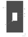
- FIG. 6 is a schematic diagram illustrating a configuration example of the window pattern 40.
- FIG. 7 is an enlarged view in which a part of the window pattern 40 is enlarged. In FIG. 7, the enlarged portion is illustrated as a rectangular shape, but of course, a pattern image continues on the outside. The same applies to the enlarged views shown below.
- a pattern image having a rectangular window 41 at the center is displayed as the window pattern 40.
- the inside 42 of the window 41 is displayed in white, and the outside 43 of the window 41 is displayed in black (shown in dark gray in the figure).
- the upper left end 44 of the window 41 is detected based on the photographed image obtained by photographing the window pattern 40 (step 111).
- a plurality of pixels 28 of the image sensor that captures the window pattern 40 are schematically illustrated.
- a pixel on which an upper left end 44 of the window 41 forms an image is detected. This can be detected from the output value of each of the plurality of pixels 28.
- this pixel is referred to as an end corresponding pixel 35.
- the checker pattern for adjustment (first pattern image) is displayed by the reference projector 15 (step 112).
- the adjustment checker pattern is a pattern image projected to adjust the projection positions of the reference projector 15 and the adjustment projector 16.
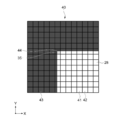
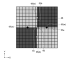
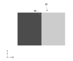
- FIG. 8 is a schematic diagram showing a configuration example of an adjustment checker pattern.
- the adjustment checker pattern 50 includes a plurality of bright portions 51, a plurality of dark portions 52, and one or more boundaries 53.
- the bright part 51 is displayed in green, and the dark part 52 is displayed in black. Between the bright part 51 and the dark part 52 is one or more boundaries 53.
- the adjustment checker pattern 50 includes a bright part 51 and a dark part 52 along the x-axis direction (first direction) and the y-axis direction (second direction), respectively. Alternatingly arranged. Each shape, size, arrangement position, and the like of the bright part 51 and the dark part 52 may be set as appropriate.
- the boundary extending in the x-axis direction is the first boundary 53a
- the boundary extending in the y-axis direction is the second boundary 53b.
- the control unit 24 functioning as a projection control unit can move the projection position of each projector 10 along each of the x-axis and y-axis directions.
- the intersection of the first boundary 53a extending in the x-axis direction and the second boundary 53b extending in the y-axis direction is set as the adjustment point 55.
- the adjustment point 55 is a point serving as a reference for adjusting the projection position.
- a frame 56 or the like indicating the adjustment point 55 may be displayed in an overlapping manner. Thereby, the user can grasp which point is used as a reference for adjustment. Note that all of the intersections in the adjustment checker pattern may be set as the adjustment points 55, or some of the intersections may be set as the adjustment points 55.
- All points of the adjustment points 55 in the adjustment checker pattern 50 are detected based on the photographed image obtained by photographing the adjustment checker pattern 50 (step 113, step 201 in FIG. 4). That is, a pixel (hereinafter referred to as an adjustment pixel) on which the adjustment point 55 forms an image among the plurality of pixels 28 is detected.
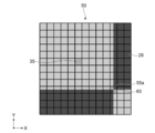
- FIG. 9 is an enlarged view for explaining detection of the adjustment pixel.
- the adjustment pixel 60 is detected based on the edge corresponding pixel 35 corresponding to the upper left edge 44 of the window 41 detected in step 111. For example, when the center adjustment point 55a shown in FIG. 8 is detected, the adjustment pixel 60 is detected based on the output value of each pixel 28 toward the lower right of the edge corresponding pixel 35.
- the output value corresponding to green (hereinafter referred to as a high output value) and the output value corresponding to black (hereinafter referred to as a low output value) along the x-axis direction from the end corresponding pixel 35.
- a high output value the output value corresponding to green
- a low output value the output value corresponding to black
- a pixel whose output value is further displaced from the pixel along the y-axis direction is detected as the adjustment pixel 60.
- the adjustment pixel may be detected by other methods.
- the window pattern 40 shown in FIG. 6 may have a shape or the like appropriately set for detecting the adjustment pixel 60.
- the window pattern 40 is set so that a position not on the boundary 53, that is, a position included in the bright part 51 or the dark part 52 can be specified. If the position in the projection image 11 can be specified, a pattern image other than the window pattern 40 may be used.
- a pattern image such as the window pattern 40 may not be used, and the adjustment pixel 60 where the adjustment point 55 forms an image directly from the adjustment checker pattern 50 may be detected.
- the detection accuracy of the adjustment pixel 60 can be improved by using the window pattern 40.
- FIG. 10 is an enlarged view for explaining detection of one or more reference pixels 65.
- a pixel 28 that is a certain pixel away from the adjustment pixel 60 in the vertical and horizontal directions with the adjustment pixel 60 as the center of point symmetry is detected as the reference pixel 65.
- the one or more reference pixels 65 include a first reference pixel 65a on which the first boundary 53a forms an image and a second reference pixel 65b on which the second boundary 53b forms an image.
- the first reference pixel 65 a includes two pixels 28 that are separated from the adjustment pixel 60 by a predetermined pixel in different directions along the x-axis direction.
- the second reference pixel 65b includes two pixels 28 that are separated from the adjustment pixel 60 by predetermined pixels in different directions along the y-axis direction. Accordingly, the four reference pixels 65 are set with the adjustment pixel 60 as the center of point symmetry.
- One or more reference pixels 65 are set in the same manner for all the adjustment pixels 60. The distance from the adjustment pixel 60 may be set as appropriate.
- step 114 and step 202 the output value from one or more reference pixels 65 is measured.
- the measured output value is stored in the storage unit 23 as a reference value.
- Projection of the adjustment checker pattern 50 by the reference projector 15 is stopped (step 115). Then, the projection position is adjusted (step 116, step 203).
- the said adjustment may be described as image distortion adjustment.
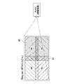
- FIG. 11 to FIG. 14 are diagrams for explaining the outline of image distortion adjustment according to the present embodiment.
- an adjustment checker pattern 50 having one intersection at the substantially center is used. That is, it is assumed that the checker pattern 50 is displayed by the reference projector 15 (illustrated by a broken line), and four reference pixels 65 are set with reference to the adjustment pixel 60 corresponding to the adjustment point 55.
- a boundary extending in the x-axis direction in the adjustment checker pattern 70 corresponds to the first corresponding boundary 73a.
- a boundary extending in the y-axis direction corresponds to the second corresponding boundary 73b. That is, the boundary at the same position as the first and second boundaries 53 a and 53 b in the adjustment checker pattern 50 displayed by the reference projector 15 is the first and second in the adjustment checker pattern 70 displayed by the adjustment projector 16. 2 corresponding boundaries 73a and 73b.
- the adjustment checker pattern 70 is projected while the projection position is moved in a unit of movement smaller than the pixel size S of the image sensor (see arrow A in FIG. 11). At this time, the output values of the four reference pixels 65 acquired from the image sensor that captures the adjustment checker pattern 70 are compared with the four reference values stored in the storage unit 23. Based on the comparison result, the projection position is adjusted. This process is executed by the control unit 24 functioning as an adjustment unit.
- the adjustment checker pattern 70 is projected by the adjustment projector 16 so that the adjustment point 75 is shifted as shown in the enlarged view of FIG.
- the output values of the two first reference pixels 65a and the two second reference pixels 65b are as follows.
- Right first reference pixel 65a Low output value
- Left first reference pixel 65a High output value
- Upper second reference pixel 65b High output value
- Lower second reference pixel 65b Low output value
- the direction toward the upper left can be calculated as the movement direction of the projection position.
- the first corresponding boundary 73a is moved to a position where it is moved to a position where the image is formed in the two first reference pixels 65a.
- the second corresponding boundary 73b is moved to a position where an image is formed in the two second reference pixels 65b.
- the adjustment in the other direction may be executed after the adjustment in one direction is completed. In that case, one of the first and second corresponding boundaries 73 a and 73 b is first moved to a position where the image is formed on the reference pixel 65.
- the projection position is adjusted so that the output value of each reference pixel 65 approaches the reference value stored in the storage unit 23. In this way, the projection position can be adjusted based on the reference value.
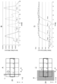
- FIG. 14 is a diagram for explaining an output value when the projection position is moved in a movement unit smaller than the pixel size S.
- FIG. 14A it is assumed that a line image L whose size in the x-axis direction is smaller than the pixel size S is moved from the pixel 28 (1) to the pixel 28 (4).
- FIG. 14B the output value of the pixel accompanying the movement of the line image L becomes unstable, and it is very difficult to specify the position of the line image L from the output value.
- FIG. 14C it is assumed that a block image B larger than the pixel size S is moved from the pixel 28 (1) to the pixel 28 (4) along the x-axis direction.
- the area value of the imaged block image B can be measured as an output value from the pixel. That is, the movement amount of the block image B and the output value from the pixel into which the block image B enters have a substantially linear relationship.
- the inventor newly found the correlation between the movement amount of the block image and the output value of a single pixel, and based on this, the checker pattern for adjustment is referred to with reference to the reference value stored in the storage unit 23.
- the adjustment of the projection position according to the present technology for moving 70 is devised. By stabilizing the slope of the output value, it is possible to adjust the position with high accuracy based on the stored reference value. Thereby, the projection position can be adjusted with high accuracy in a minute unit smaller than the pixel size S of the image sensor.
- the size of the bright part 51 and the dark part 52 of the adjustment checker pattern 50 (70) is larger than the pixel size S, but the condition is substantially satisfied by forming the checker pattern.
- a plurality of adjustment points 55 are set in the adjustment check pattern 50 shown in FIG. As shown in step 204 of FIG. 4, adjustment is performed at all adjustment points 55. This enables image distortion adjustment with high accuracy.
- the number of adjustment points 55 is not limited.
- the adjustment checker pattern 70 is displayed by the adjustment projector 16 (step 117).
- the output values of the four reference pixels 65 are measured (step 118, step 301), and the movement direction of the projection position is calculated (step 119, step 302).
- the image distortion adjustment value is set when the moving direction is calculated.
- the image distortion adjustment value is a preset value and is a value that decreases from a predetermined value to a value less than 1 according to a predetermined rule. For example, a value such as a value (128, 64, 32... 1) that is halved sequentially from 128 is used.
- the method for setting the image distortion adjustment value is not limited.
- step 303 it is determined whether or not the image distortion adjustment value is less than 1.
- a value obtained by adding a sign to the image distortion adjustment value is adjusted as an image distortion adjustment command, with one of the vertical directions as a positive direction and one of the left and right directions as a positive direction. It is output to the projector 16 (step 120, step 304).
- the projection position is adjusted based on the image distortion adjustment command value (step 121). For example, when a command value of +128 is output with a positive value in the vertical direction, the projection position is moved upward by a distance corresponding to (movement unit ⁇ 128). Thereafter, this process is repeated until the image distortion adjustment value converges to less than 1. By such processing, it is possible to adjust the image distortion with high accuracy while suppressing the calculation amount.
- the adjustment check pattern 70 is projected while moving the projection position using the distance smaller than the pixel size S as the movement unit. At that time, the output value of the reference pixel 65 is acquired from the image sensor. When the corresponding boundary 73 of the adjustment check pattern 70 is imaged on the reference pixel 65, the output value is displaced according to the displacement of the size of the bright portion 51 imaged on the reference pixel 65. Therefore, by comparing the output value of the reference pixel 65 with the reference value stored in the storage unit 23, the projection position can be adjusted with high accuracy using the boundary 53 and the corresponding boundary 73 as a reference.
- the projection position can be adjusted with an accuracy higher than the resolution of the camera 21, and a high-precision adjustment independent of the resolution of the camera 21 is possible. Further, it is not necessary to perform zooming for each adjustment point 55, and it is possible to adjust the positions of the plurality of adjustment points 55 in the image only by collectively shooting the entire area of the adjustment check patterns 50 and 70. As a result, the adjustment time can be shortened. Note that the smaller the resolution of the camera 21, the more sampling points of area value, so that the adjustment accuracy may be improved.
- the adjustment point 55 as the center of point symmetry and making the boundary part separated from the top, bottom, left and right as detection targets, the adjustment directions in the top, bottom, left and right can be detected simultaneously. As a result, the processing time can be further shortened.
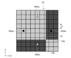
- FIG. 15 is a schematic diagram for explaining another example of adjustment of the projection position using the present technology.
- the adjustment of the projection position has been described by taking as an example the case where two images are superimposed on the same position.
- the present technology is not limited to this, and the present technology can also be applied when two images are connected as shown in FIG.
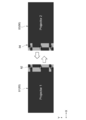
- the marginal region 82 at the right end of the projection image 81 projected by the reference projector (Projector1) and the marginal region 84 at the left end of the projection image 83 projected by the adjustment projector (Projector2) are overlapped.
- the first pattern image 85 and the second pattern image 86 in which checker patterns are respectively set in the marginal areas 82 and 84 may be used.
- a checker pattern may be formed on the entire image, and an adjustment point that can be aligned may be selected as appropriate.
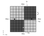
- the number of connected images is not limited, and four images 90 may be connected as shown in FIG. Also in this case, by setting a checker pattern in the marginal area 91, an image can be connected with high accuracy by applying the present technology. Even when a high-resolution image of 4K or 8K is connected, it is not necessary to zoom the connection portion, and the projection position can be easily adjusted by collectively shooting the entire area.
- FIG. 17 is a schematic diagram illustrating another configuration example of the pattern image for adjustment according to the present technology.
- This pattern image 95 has only a boundary 96 extending in the y-axis direction.
- a pattern image including at least a boundary extending in a direction orthogonal to the adjustment direction may be used.
- the color of the bright part and the dark part of the checker pattern is not limited, and a pattern image in which the luminance changes at the boundary may be used as appropriate. Note that when the bright part is displayed in white, a registration shift may occur, but such a problem can be avoided by displaying the bright part in green as described above.
- first pattern image projected by the reference projector and the second pattern image projected by the adjustment projector are exactly the same image.
- the error at each adjustment point may be displayed in a list after the adjustment of the projection position. This makes it possible to grasp the adjustment accuracy. Further, the adjustment process may be executed again by replacing the reference projector and the adjustment projector. Thereby, it is possible to reduce the influence of the measurement error due to the noise of the image sensor or the like.
- the image processing apparatus shown in FIG. 1 may be realized by a camera that functions independently of each other and a computer such as a PC connected thereto.
- the PC or the like functions as an information processing apparatus according to the present technology including the acquisition unit, the projection control unit, the storage unit, and the adjustment unit according to the present technology.
- the effects described in the present disclosure are merely examples and are not limited, and may have other effects.
- the above description of the plurality of effects does not necessarily mean that these effects are necessarily exhibited at the same time. It means that at least one of the above-described effects can be obtained depending on conditions and the like, and of course there is a possibility that an effect not described in the present disclosure is exhibited.
- An acquisition unit that acquires an output value of each of the plurality of pixels from an image sensor including a plurality of pixels having a predetermined pixel size; It is possible to project a first pattern image including one or more boundaries serving as a boundary between a bright part and a dark part by the first projection device, and a distance smaller than the predetermined pixel size is a unit for moving the projection position.
- a projection control unit capable of causing the second projection device to project a second pattern image including one or more corresponding boundaries corresponding to the one or more boundaries; Storage that stores, as a reference value, an output value of one or more reference pixels that are acquired from the image sensor that captures the first pattern image projected by the first projection device and forms an image of the boundary.
- An information processing apparatus comprising: an adjustment unit that adjusts the projection position by comparing the output value of the predetermined reference pixel and the stored reference value for each movement of the projection position.
- the one or more boundaries have a first boundary extending in a first direction;
- the one or more corresponding boundaries have a first corresponding boundary extending in the first direction;
- the projection control unit is capable of moving the projection position in the movement unit along a second direction orthogonal to the first direction.
- the one or more boundaries have a second boundary extending in the second direction;
- the one or more corresponding boundaries have a second corresponding boundary extending in the first direction;
- the projection control unit is capable of moving the projection position in units of movement along each of the first and second directions.
- the one or more reference pixels include a first reference pixel on which the first boundary forms an image, and a second reference pixel on which the second boundary forms an image,
- the first and second reference pixels are set with an intersection between the first boundary and the second boundary as an adjustment point, and a pixel on which the adjustment point is imaged as a reference.
- the first pattern image is a checker pattern in which the bright portions and the dark portions are alternately arranged along each of the first and second directions.
- the first reference pixel is two pixels separated by predetermined pixels in different directions along a first direction from a pixel at which an intersection of the checker pattern forms an image
- the second reference pixel is two pixels separated by predetermined pixels in different directions along a second direction from a pixel at which an intersection of the checker patterns forms an image.
- the second pattern image is the same image as the first pattern image.
- S Pixel size 10 ... Projector 11 ... Image 12 ... Projection unit 15 ... Reference projector 16 ... Adjustment projector 20 ... Image processing device 21 ... Camera (imaging device) DESCRIPTION OF SYMBOLS 23 ... Memory
Landscapes
- Engineering & Computer Science (AREA)
- Multimedia (AREA)
- Signal Processing (AREA)
- Physics & Mathematics (AREA)
- General Physics & Mathematics (AREA)
- Computer Hardware Design (AREA)
- Theoretical Computer Science (AREA)
- General Health & Medical Sciences (AREA)
- Biomedical Technology (AREA)
- Health & Medical Sciences (AREA)
- Geometry (AREA)
- Controls And Circuits For Display Device (AREA)
- Projection Apparatus (AREA)
- Testing, Inspecting, Measuring Of Stereoscopic Televisions And Televisions (AREA)
Abstract
所定の画素サイズを有する複数の画素の各々の出力値を取得する取得部と、明部と暗部との境界となる1以上の境界を含む第1のパターン画像を第1の投射装置により投射させ、画素サイズよりも小さい距離を移動単位として、1以上の境界に対応する1以上の対応境界を含む第2のパターン画像を第2の投射装置により投射させる投射制御部とを有する。また情報処理装置は、投射された第1のパターン画像の境界が結像する所定の1以上の基準画素の出力値を基準値として記憶する記憶部と、第1のパターン画像の投射が停止された後に上記の移動単位で投射位置を移動させながら投射された第2のパターン画像における基準画素の出力値と、記憶された基準値とを、投射位置の移動ごとに比較して投射位置を調整する調整部とを有する。
Description
本技術は、複数の投射画像の位置を調整するための情報処理装置、情報処理方法、プログラム、調整装置、及び画像表示システムに関する。
従来、複数のプロジェクタによりスクリーン上に複数の画像を投射する技術が用いられている。例えば複数の視差画像を投射することで立体画像を表示する技術や、同じ画像を重ねて投射することで高輝度の画像を表示する技術が知られている。また複数の画像を並べて投射することで大画面での表示が可能となる。
特許文献1に記載の画像投射位置調整装置では、2つの異なるプロジェクタから異なる色のテストパターンが互いに重なり合うように投射される。そして投射された2つのテストパターンがカメラにより撮影され、撮影画像内の色情報の変化をもとに投射位置が調整されている(例えば特許文献1の段落[0043]-[0061]図5等)。
このように複数の画像が投射される際の投射位置を高精度に調整することが求められている。
以上のような事情に鑑み、本技術の目的は、投射画像の投射位置を高精度に調整することが可能となる情報処理装置、情報処理方法、プログラム、調整装置、及び画像表示システムを提供することにある。
上記目的を達成するため、本技術の一形態に係る情報処理装置は、取得部と、投射制御部と、記憶部と、調整部とを具備する。
前記取得部は、所定の画素サイズを有する複数の画素を含む撮像素子から前記複数の画素の各々の出力値を取得する。
前記投射制御部は、明部と暗部との境界となる1以上の境界を含む第1のパターン画像を第1の投射装置により投射させることが可能であり、前記所定の画素サイズよりも小さい距離を投射位置の移動単位として、前記1以上の境界に対応する1以上の対応境界を含む第2のパターン画像を第2の投射装置により投射させることが可能である。
前記記憶部は、前記第1の投射装置により投射された前記第1のパターン画像を撮影する前記撮像素子から取得された、前記境界が結像する所定の1以上の基準画素の出力値を基準値として記憶する。
前記調整部は、前記第1のパターン画像の投射が停止された後に前記第2の投射装置により前記移動単位で前記投射位置を移動させながら投射された前記第2のパターン画像を撮影した前記撮像素子から取得された前記所定の基準画素の出力値と、前記記憶された基準値とを、前記投射位置の移動ごとに比較して前記投射位置を調整する。
本技術では、画素サイズよりも小さい距離を移動単位として投射位置を移動させながら第2のパターン画像が投射される。そしてその際に撮像素子から基準画素の出力値が取得される。第2のパターン画像の対応境界が基準画素に結像される際には、基準画素に結像される明部の大きさの変位に応じて出力値が変位する。従って基準画素の出力値と基準値とを比較することで、第1のパターン画像の境界と、第2のパターン画像の対応境界とを基準として、高精度に投射位置を調整することができる。
前記1以上の境界は、第1の方向に延在する第1の境界を有してもよい。この場合、前記1以上の対応境界は、前記第1の方向に延在する第1の対応境界を有してもよい。また前記投射制御部は、前記第1の方向に直交する第2の方向に沿って前記投射位置を前記移動単位で移動させることが可能であってもよい。
これにより第2の方向において高精度に投射位置を調整することが可能となる。
これにより第2の方向において高精度に投射位置を調整することが可能となる。
前記1以上の境界は、前記第2の方向に延在する第2の境界を有し、
前記1以上の対応境界は、前記第1の方向に延在する第2の対応境界を有し、
前記投射制御部は、前記第1及び前記第2の方向の各々に沿って、前記投射位置を前記移動単位で移動させることが可能である
情報処理装置。
これにより第1及び第2の方向において高精度に投射位置を調整することが可能となる。
前記1以上の対応境界は、前記第1の方向に延在する第2の対応境界を有し、
前記投射制御部は、前記第1及び前記第2の方向の各々に沿って、前記投射位置を前記移動単位で移動させることが可能である
情報処理装置。
これにより第1及び第2の方向において高精度に投射位置を調整することが可能となる。
前記1以上の基準画素は、前記第1の境界が結像する第1の基準画素と、前記第2の境界が結像する第2の基準画素とを有してもよい。この場合、前記第1及び前記第2の基準画素は、前記第1の境界と前記第2の境界との交点を調整ポイントとして、当該調整ポイントが結像される画素を基準として設定されてもよい。
これにより調整ポイントを基準として高精度に投射位置を調整することが可能となる。
これにより調整ポイントを基準として高精度に投射位置を調整することが可能となる。
前記第1のパターン画像は、前記第1及び前記第2の方向の各々に沿って前記明部及び前記暗部が交互に配置されたチェッカーパターンであってもよい。この場合、前記第1の基準画素は、前記チェッカーパターンの交点が結像する画素から第1の方向に沿って互いに異なる向きに所定の画素分離れた2つの画素であってもよい。また前記第2の基準画素は、前記チェッカーパターンの交点が結像する画素から第2の方向に沿って互いに異なる向きに所定の画素分離れた2つの画素であってもよい。
このようにチェッカーパターンが有する複数の交点をそれぞれ調整ポイントとして、各調整ポイントを基準として4つの基準画素が設定される。これにより高精度に投射位置を調整することができる。
このようにチェッカーパターンが有する複数の交点をそれぞれ調整ポイントとして、各調整ポイントを基準として4つの基準画素が設定される。これにより高精度に投射位置を調整することができる。
前記第2のパターン画像は、前記第1のパターン画像と同じ画像であってもよい。
これにより第1の投射装置からの投射画像と、第2の投射装置からの投射画像とを、高い精度で重ねあわせることができる。
これにより第1の投射装置からの投射画像と、第2の投射装置からの投射画像とを、高い精度で重ねあわせることができる。
本技術の一形態に係る情報処理方法は、所定の画素サイズを有する複数の画素を含む撮像素子から前記複数の画素の各々の出力値を取得することが可能なコンピュータによる情報処理方法であって、
明部と暗部との境界となる1以上の境界を含む第1のパターン画像を第1の投射装置により投射させることを含む。
前記第1の投射装置により投射された前記第1のパターン画像を撮影する前記撮像素子から取得した、前記境界が結像する所定の1以上の基準画素の出力値が基準値として記憶される。
前記第1のパターン画像の投射を停止させた後に、前記所定の画素サイズよりも小さい距離を投射位置の移動単位として、前記1以上の境界に対応する1以上の対応境界を含む第2のパターン画像が、前記投射位置を移動させながら第2の投射装置により投射される。
前記投射された前記第2のパターン画像を撮影した前記撮像素子から取得した前記所定の基準画素の出力値と、前記記憶された基準値とが、前記投射位置の移動ごとに比較されることで前記投射位置が調整される。
本技術の一形態に係るプログラムは、所定の画素サイズを有する複数の画素を含む撮像素子から前記複数の画素の各々の出力値を取得することが可能なコンピュータに、以下のステップを実行させる。
明部と暗部との境界となる1以上の境界を含む第1のパターン画像を第1の投射装置により投射させるステップ。
前記第1の投射装置により投射された前記第1のパターン画像を撮影する前記撮像素子から取得された、前記境界が結像する所定の1以上の基準画素の出力値を基準値として記憶するステップ。
前記第1のパターン画像の投射を停止させた後に、前記所定の画素サイズよりも小さい距離を投射位置の移動単位として、前記1以上の境界に対応する1以上の対応境界を含む第2のパターン画像を、前記投射位置を移動させながら第2の投射装置により投射させるステップ。
前記投射された前記第2のパターン画像を撮影した前記撮像素子から取得された前記所定の基準画素の出力値と、前記記憶された基準値とを、前記投射位置の移動ごとに比較して前記投射位置を調整するステップ。
本技術の一形態に係る調整装置は、撮像素子と、投射制御部と、記憶部と、調整部とを具備する。
前記撮像素子は、所定の画素サイズを有する複数の画素を含む。
前記投射制御部は、明部と暗部との境界となる1以上の境界を含む第1のパターン画像を第1の投射装置により投射させることが可能であり、前記所定の画素サイズよりも小さい距離を投射位置の移動単位として、前記1以上の境界に対応する1以上の対応境界を含む第2のパターン画像を第2の投射装置により投射させることが可能である。
前記記憶部は、前記第1の投射装置により投射された前記第1のパターン画像を撮影する前記撮像素子から出力された、前記境界が結像する所定の1以上の基準画素の出力値を基準値として記憶する。
前記調整部は、前記第1のパターン画像の投射が停止された後に前記第2の投射装置により前記移動単位で前記投射位置を移動させながら投射された前記第2のパターン画像を撮影した前記撮像素子から出力された前記所定の基準画素の出力値と、前記記憶された基準値とを、前記投射位置の移動ごとに比較して前記投射位置を調整する。
本技術の一形態に係る画像表示システムは、投射部と、前記撮像素子と、前記投射制御部と、前記記憶部と、前記調整部とを具備する。
前記投射部は、画像を投射可能な第1の投射装置及び第2の投射装置を有する。
前記投射部は、画像を投射可能な第1の投射装置及び第2の投射装置を有する。
以上のように、本技術によれば、投射画像の投射位置を高精度に調整することが可能となる。なお、ここに記載された効果は必ずしも限定されるものではなく、本開示中に記載されたいずれかの効果であってもよい。
以下、本技術に係る実施形態を、図面を参照しながら説明する。
[画像表示システムの構成]
図1は、本技術の一実施形態に係る画像表示システムの構成例を示す概略図である。画像表示システム100は、スクリーン1等に画像を投射可能な複数のプロジェクタ(投射装置)10と、各プロジェクタ10の動作を制御可能な画像処理装置(調整装置)20と、各プロジェクタ10に投射対象となる画像の情報を含む映像信号を供給する映像供給装置30とを有する。映像供給装置30は、静止画像及び動画像の両方を含む映像信号を各プロジェクタ10に供給可能である。
図1は、本技術の一実施形態に係る画像表示システムの構成例を示す概略図である。画像表示システム100は、スクリーン1等に画像を投射可能な複数のプロジェクタ(投射装置)10と、各プロジェクタ10の動作を制御可能な画像処理装置(調整装置)20と、各プロジェクタ10に投射対象となる画像の情報を含む映像信号を供給する映像供給装置30とを有する。映像供給装置30は、静止画像及び動画像の両方を含む映像信号を各プロジェクタ10に供給可能である。
プロジェクタ10は、例えばプレゼンテーション用、もしくはデジタルシネマ用のプロジェクタとして用いられる。プロジェクタ10は、図示しない光源と、映像信号をもとに光源からの光を変調する光変調素子と、光変調素子により変調された変調光(画像)を投射する投射部とを有する(いずれも不図示)。光源としては、例えばLED(Light Emitting Diode)やLD(Laser Diode)等の固体光源が用いられる。光変調素子としては、例えば液晶パネルやデジタルマイクロミラーデバイス(DMD)等が用いられる。
本実施形態では、複数のプロジェクタ10の各々からカラー画像11が投射される。複数の画像11が所定の投射位置で同時に投射されることで、例えば立体画像の表示、高輝度の画像の表示、あるいは大画面での画像表示が実現される。なお全てのプロジェクタ10から常に同時に画像が表示される場合に限定されない。
本実施形態では、同じ機種のプロジェクタ10が複数並べられて使用される。各プロジェクタ10は、いわゆる4Kハイビジョンや8Kスーパーハイビジョンと呼ばれる高解像度の画像を表示可能である。そして電気的補正ブロックとして1/4ピクセル単位で画像11の投射位置を制御することが可能である。すなわち1/4ピクセル単位を移動単位として投射位置を移動させることができる。投射位置を移動させるための具体的な構成や方法は限定されない。
複数のプロジェクタ10により、本実施形態に係る投射部12が実現される。投射部12の具体的な構成は上記したものに限定されず適宜設定されてよい。各プロジェクタ10の具体的な構成、投射される画像11の解像度、投射位置の制御の移動単位等も適宜設定されてよい。複数のプロジェクタ10内に異なる機種のプロジェクタが含まれてもよい。また画像11を投射する投射装置として、プロジェクタ10以外の装置が用いられてもよい。
映像供給装置30は、例えばPC(Personal Computer)により実現可能である。映像供給装置30内には、映像信号を記憶して各プロジェクタ10に送信するメディアサーバ31が構成されている。また映像供給装置30には、本技術で用いられる投射位置の調整用のパターン画像等が、その他の映像信号のソース32として格納されている。調整用のパターン画像は、各プロジェクタ10に内蔵されていてもよい。
映像供給装置30の具体的な構成は限定されない。映像を供給するための方法や構成、プロジェクタ10との接続形態や通信方法等は、適宜設定されてよい。例えばネットワーク等を介して各装置が接続されてもよい。
画像処理装置20は、プロジェクタ10により投射された画像11を撮影するカメラ(撮像装置)21と、ユーザの操作を受け付ける操作部22と、撮像された画像11や種々のパラメータ等を記憶する記憶部23と、種々の制御及び演算を実行する制御部24とを有する。
カメラ21は、所定の画素サイズ(ピクセルサイズ)を有する複数の画素を含む撮像素子を有する(いずれも不図示)。撮像素子としては、例えばCMOS(Complementary Metal Oxide Semiconductor)センサやCCD(Charge Coupled Device)センサ等のイメージセンサが用いられる。
本技術では、カメラ21として、画素サイズが投射位置の移動単位よりも大きいものが用いられる。逆に言うと、投射画像11を撮影する撮像素子の画素サイズよりも小さい距離を移動単位として、投射位置の移動が実行される。従って複数回の移動が実行されることで、その移動量が、撮像素子の画素サイズに等しくなる、あるいは画素サイズを超えることになる。
典型的には、カメラ21として、プロジェクタ10の解像度よりも小さい解像度のカメラが用いられる。例えば4Kの画像を投射可能なプロジェクタ10に対して、1920×1080(pixel)の解像度を有するHDカメラが用いられる。本技術では、このような解像度が小さいカメラ21を用いて、高解像度の投射画像11の投射位置を高精度に調整することが可能となる。なおプロジェクタ10とカメラ21との解像度が上記した関係である場合に限定されず、撮像素子の画素サイズよりも小さい距離で投射位置が調整される場合には、本技術を適用可能である。
またカメラ21の解像度がプロジェクタ10の解像度よりも高く、撮像素子上に結像された投射画像の移動単位よりカメラ21の本来の画素サイズが小さい場合でも、複数の画素を疑似的に1画素とみなすことにより、本技術を適用することが可能である。例えば複数の画素の出力を合算することで、これらを疑似的に1画素とみなすことができる。この場合、疑似的に1画素とみなされた画素のサイズが本技術に係る画素サイズとなる。
なお本開示では、カラー画像11を形成する単位となる1つの画素(単位画素)を基準として説明を行う。単位画素を構成する副画素(サブピクセル)からの出力値を用いて本技術が実行されてもよい。
操作部22は、例えば液晶、EL(Electro-Luminescence)等を用いた表示デバイスからなるディスプレイ26と、これと一体的に構成されたタッチパネル27とを有する。
記憶部23は、例えばROM(Read Only Memory)やHDD(Hard Disk Drive)等からなり、フレームメモリとして機能する。また記憶部80には、撮像素子から出力された複数の画素の各々の出力値が記憶される。
制御部24は、画像処理装置20内の各ブロックの動作を制御する。また制御部24は、所定のコマンドを各プロジェクタ10に出力することで、各プロジェクタ10の動作を制御することが可能である。なお画像処理装置20と各プロジェクタ10との接続形態や通信方法は限定されない。また各プロジェクタ10の動作を制御するための構成や方法も限定されない。
制御部24は、例えばCPU(Central Processing Unit)、RAM(Random Access Memory)、及びROM等を有し、CPUがROMに予め記録されているプログラムをRAMにロードして実行することにより、所定の処理が実行される。またCPUが所定のプログラムを実行することで、所定の機能ブロックが実現される。制御部24の具体的な構成は限定されず、任意のハードウェア及びソフトウェアが用いられてよい。本実施形態では、制御部24により、取得部、投射制御部、及び調整部が実現される。
プログラムは、例えば記録媒体を介してインストールされてもよいし、グローバルネットワーク等を介してインストールされてもよい。またプログラムは、時系列に処理が行われるプログラムであってもよいし、並列に、あるいは呼び出しが行われたとき等の必要なタイミングで処理が行われるプログラムであってもよい。
[画像表示システムの動作]
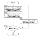
画像表示システム100の動作として、主に投射位置の調整について説明する。図2及び図3は、画像処理装置20、基準プロジェクタ(Reference Projector)15、及び調整プロジェクタ(Adjustment Projector)16の各動作例を示すシーケンス図である。図4及び図5は、画像処理装置20の動作例を示すフローチャートである。
画像表示システム100の動作として、主に投射位置の調整について説明する。図2及び図3は、画像処理装置20、基準プロジェクタ(Reference Projector)15、及び調整プロジェクタ(Adjustment Projector)16の各動作例を示すシーケンス図である。図4及び図5は、画像処理装置20の動作例を示すフローチャートである。
本技術では、2つのプロジェクタ10のうちの一方が基準プロジェクタ15に設定され、他方が調整プロジェクタ16に設定される。そして基準プロジェクタ15により投射された投射画像11に対して、調整プロジェクタ16の投射画像11の投射位置が調整される。なお基準プロジェクタ15及び調整プロジェクタ16は、本実施形態において、第1の投射装置及び第2の投射装置にそれぞれ相当する。
複数のプロジェクタ10に対して、基準プロジェクタ15及び調整プロジェクタ16をどのように設定するかは任意に定められてよい。例えば1つのプロジェクタ15を基準プロジェクタとして設定し、その他のプロジェクタ10が調整プロジェクタ16として設定される。あるいは、基準プロジェクタ15及び調整プロジェクタ16のペアが順次選択されてもよい。互いの調整位置を調整し合うことが必要な2つプロジェクタ10に対して、いずれか一方が基準プロジェクタ15として設定され、他方が調整プロジェクタ16として設定されればよい。
まず基準プロジェクタ15によりホワイトフラットパターンが表示される(ステップ101)。ホワイトフラットパターンは、全ての画素が白色で表示されたパターン画像である。なお調整プロジェクタ16からのテストパターンの投射は停止される(ステップ102)。
スクリーン1に投射されたホワイトフラットパターンを基準として、制御部24により、カメラ21のズーム(画角)が調整される(ステップ103)。典型的には、基準プロジェクタ15からの投射画像の全体が撮影範囲に含まれるように、ズームが調整される。ズームを調整するためにホワイトフラットパターンとは異なるパターン画像が用いられてもよい。
基準プロジェクタ15によりチェッカーパターンが表示される(ステップ104)。当該チェッカーパターンを基準として、制御部24によりカメラ21のフォーカスが調整される(ステップ105)。フォーカスの調整方法等は限定されず、またフォーカス調整用のパターン画像も限定されない。
基準プロジェクタ15により再びホワイトフラットパターンが表示される(ステップ106)。当該ホワイトフラットパターンを基準として、制御部24により、カメラ21のホワイトバランスが調整される(ステップ107)。ホワイトバランスを調整するために他のパターン画像が投射されてもよい。
基準プロジェクタ15によりグリーンフラットパターンが表示される(ステップ108)。グリーンフラットパターンは、全ての画素が緑色で表示されたパターン画像である。グリーンフラットパターンを基準として、制御部24により、カメラ21のアイリスが調整される(ステップ109)。アイリスを調整するために他のパターン画像が投射されてもよい。
基準プロジェクタ15によりウィンドウパターンが表示される(ステップ110)。ウィンドウパターンは、基準プロジェクタ15により投射される画像内の特定の位置を画像処理装置20が検出するためのパターン画像である。
図6は、ウィンドウパターン40の構成例を示す概略図である。図7は、ウィンドウパターン40の一部を拡大した拡大図である。図7では、拡大した部分が矩形状で図示されているが、もちろんその外側にもパターン画像が続いている。このことは以下に示す拡大図でも同様である。
本実施形態では、ウィンドウパターン40として、中央に矩形状のウィンドウ41を有するパターン画像が表示される。ウィンドウ41の内部42は白色で表示され、ウィンドウ41の外部43は黒色で表示される(図中では、濃いグレーで図示されている)。
ウィンドウパターン40を撮影した撮影画像をもとに、ウィンドウ41の左上の端部44が検出される(ステップ111)。図7では、ウィンドウパターン40を撮影する撮像素子の複数の画素28が模式的に図示されている。この複数の画素28のうちの、ウィンドウ41の左上の端部44が結像する画素が検出される。これは複数の画素28の各々の出力値から検出可能である。以下のこの画素を端部対応画素35と記載する。
基準プロジェクタ15により調整用チェッカーパターン(第1のパターン画像)が表示される(ステップ112)。調整用チェッカーパターンは、基準プロジェクタ15及び調整プロジェクタ16の投射位置を調整するために投射されるパターン画像である。
図8は、調整用チェッカーパターンの構成例を示す概略図である。調整用チェッカーパターン50は、複数の明部51と、複数の暗部52と、1以上の境界53とを有する。明部51は緑色で表示され、暗部52は黒色で表示される。明部51と暗部52との間が1以上の境界53となる。
図8に示すように、本実施形態では、調整用チェッカーパターン50は、x軸方向(第1の方向)及びy軸方向(第2の方向)の各々に沿って明部51及び暗部52が交互に配置されてなる。明部51及び暗部52の各形状やサイズ、配置位置等は適宜設定されてよい。
また1以上の境界53のうち、x軸方向に延在する境界は第1の境界53aとなり、y軸方向に延在する境界は第2の境界53bとなる。投射制御部として機能する制御部24は、x軸及びy軸方向の各々に沿って、各プロジェクタ10の投射位置をでそれぞれ移動させることが可能である。
x軸方向に延在する第1の境界53aと、y軸方向に延在する第2の境界53bとの交点は、調整ポイント55として設定される。調整ポイント55は、投射位置の調整の基準となるポイントである。基準プロジェクタ15により調整用チェッカーパターン50が表示される際には、図8に示すように、調整ポイント55を示す枠56等が重畳して表示されてもよい。これによりユーザがどのポイントを基準として調整が行われるかを把握することができる。なお調整用チェッカーパターン内の交点の全てが調整ポイント55として設定されてもよいし、一部の交点が調整ポイント55として設定されてもよい。
調整用チェッカーパターン50を撮影した撮影画像をもとに、調整用チェッカーパターン50内の調整ポイント55の全点が検出される(ステップ113、図4のステップ201)。すなわち複数の画素28のうちの調整ポイント55が結像する画素(以下調整画素と記載する)が検出される。
図9は、調整画素の検出を説明するための拡大図である。調整画素60の検出は、ステップ111にて検出されたウィンドウ41の左上の端部44に対応する端部対応画素35をもとに実行される。例えば図8に示す中央の調整ポイント55aを検出する際には、端部対応画素35の右下に向けて、各画素28の出力値をもとに、調整画素60が検出される。
例えば端部対応画素35からx軸方向に沿って、出力値が緑色に対応する出力値(以下高出力値と記載する)と黒色に対応する出力値(以下低出力値と記載する)の間となる画素が検出される。当該画素からy軸方向に沿って、さらに出力値が変位する画素が調整画素60として検出される。その他の方法により調整画素が検出されてもよい。
図6に示すウィンドウパターン40は、調整画素60の検出のために適宜その形状等が設定されてよい。例えば調整用チェッカーパターン50において、境界53上ではない位置、すなわち明部51又は暗部52内に含まれる位置が特定可能なように、ウィンドウパターン40が設定される。また投射画像11内の位置が特定可能であるのならばウィンドウパターン40以外のパターン画像が用いられてもよい。
なおウィンドウパターン40等のパターン画像が用いられず、調整用チェッカーパターン50から直接調整ポイント55が結像する調整画素60が検出されてもよい。一方で、ウィンドウパターン40が用いられることで、調整画素60の検出精度を向上させることができる。
調整画素60を基準として、調整用チェッカーパターン50内の境界53が結像する1以上の基準画素が検出される(ステップ114、ステップ202)。図10は、1以上の基準画素65の検出を説明するための拡大図である。本実施形態では、調整画素60を点対称の中心として、調整画素60から一定の画素分上下左右に離れた画素28が基準画素65として検出される。
1以上の基準画素65は、第1の境界53aが結像する第1の基準画素65aと、第2の境界53bが結像する第2の基準画素65bとを有する。図10に示すように、第1の基準画素65aは、調整画素60からx軸方向に沿って互いに異なる向きに所定の画素分離れた2つの画素28からなる。また第2の基準画素65bは、調整画素60からy軸方向に沿って互いに異なる向きに所定の画素分離れた2つの画素28からなる。従って調整画素60を点対称の中心として、4つの基準画素65が設定されることになる。1以上の基準画素65は、全ての調整画素60に対して同様に設定される。また調整画素60からの距離は適宜設定されてもよい。
またステップ114及びステップ202では、1以上の基準画素65からの出力値が測定される。測定された出力値は、基準値として記憶部23に記憶される。
基準プロジェクタ15による調整用チェッカーパターン50の投射が停止される(ステップ115)。そして投射位置の調整が実行される(ステップ116、ステップ203)。以下、投射位置の調整の概要を説明するが、当該調整を画歪調整と記載する場合がある。
図11-図14は、本実施形態に係る画歪調整の概要を説明するための図である。以下では、説明を分かりやすくするために、略中央に1つの交点を有する調整用チェッカーパターン50が用いられるとする。すなわち当該チェッカーパターン50が基準プロジェクタ15により表示され(破線で図示)、調整ポイント55に対応する調整画素60を基準として、4つの基準画素65が設定されたとする。
その後、調整用チェッカーパターン50の投射が停止され、調整プロジェクタ16により、同じ調整用チェッカーパターン70(第2のパターン画像)が表示される(実線で表示)。この調整用チェッカーパターン70内のx軸方向に延在する境界が、第1の対応境界73aに相当する。またy軸方向に延在する境界が、第2の対応境界73bに相当する。すなわち基準プロジェクタ15により表示される調整用チェッカーパターン50内の第1及び第2の境界53a及び53bと同じ位置にある境界は、調整プロジェクタ16により表示される調整用チェッカーパターン70において第1及び第2の対応境界73a及び73bとなる。
調整用チェッカーパターン70は、撮像素子の画素サイズSよりも小さい移動単位で投射位置を移動されながら投射される(図11の矢印A参照)。この際、調整用チェッカーパターン70を撮影する撮像素子から取得された4つの基準画素65の各出力値と、記憶部23に記憶された4つの基準値がそれぞれ比較される。そしてその比較結果をもとに、投射位置の調整が実行される。この処理は、調整部として機能する制御部24により実行される。
例えば図12に示す拡大図のように、調整ポイント75がずれた位置となるように、調整プロジェクタ16により調整用チェッカーパターン70が投射されたとする。この際2つの第1の基準画素65aと、2つの第2の基準画素65bの各出力値は、以下のようになる。
右側の第1の基準画素65a…低出力値
左側の第1の基準画素65a…高出力値
上側の第2の基準画素65b…高出力値
下側の第2の基準画素65b…低出力値
右側の第1の基準画素65a…低出力値
左側の第1の基準画素65a…高出力値
上側の第2の基準画素65b…高出力値
下側の第2の基準画素65b…低出力値
この結果をもとに、調整用チェッカーパターン70を移動させる方向を検出することが可能である。図12に示す例では、投射位置の移動方向として左上へ向かう方向が算出可能である。その方向に投射位置を移動させることで、図13に示すように、第1の対応境界73aが、2つの第1の基準画素65a内に結像される位置に移動される位置に移動される。また第2の対応境界73bが、2つの第2の基準画素65b内に結像される位置に移動される。なお1方向への調整が終了してからもう一方の方向への調整が実行されてもよい。その場合、第1及び第2の対応境界73a及び73bのいずれかがまず基準画素65に結像される位置に移動される。
投射位置の移動単位は、画素サイズSよりも小さいので、基準画素65に対応境界73が結像される位置の中で、さらに投射位置の調整が必要となる。本実施形態では、各基準画素65の出力値が記憶部23に記憶された基準値に近づくように、投射位置が調整される。このように基準値を基準とした投射位置の調整が可能となる。
図14は、画素サイズSよりも小さい移動単位にて投射位置を移動させた場合における出力値について説明するための図である。例えば図14Aに示すように、x軸方向でのサイズが画素サイズSよりも小さいライン画像Lを画素28(1)から画素28(4)まで移動させるとする。この場合図14Bに示すように、ライン画像Lの移動にともなう画素の出力値は不安定となり、出力値からライン画像Lの位置を特定することは非常に難しい。
一方図14Cに示すように、画素サイズSよりも大きいブロック画像Bをx軸方向に沿って画素28(1)から画素28(4)まで移動させるとする。この場合、結像されるブロック画像Bの面積分値が、画素からの出力値として測定可能となる。すなわちブロック画像Bの移動量と、ブロック画像Bが進入する画素からの出力値とが、略リニアな関係となる。
本発明者は、このブロック画像の移動量と単一画素の出力値との相関性を新たに見出し、これをもとに、記憶部23に記憶された基準値を参照しながら調整用チェッカーパターン70を移動させる、本技術に係る投射位置の調整を考案した。出力値の傾きを安定させることで、記憶された基準値をもとに高精度の位置調整が可能となる。これにより撮像素子の画素サイズSよりも小さい微小単位にて高精度に投射位置の調整が可能となる。
調整用チェッカーパターン50(70)の明部51及び暗部52のサイズは、画素サイズSよりも大きいことが条件となるが、チェッカーパターンを形成することにより、その条件はほぼ満たされることになる。
図8に示す調整用チェックパターン50には、複数の調整ポイント55が設定されている。図4のステップ204に示すように、全調整ポイント55にて調整が実行される。これにより高い精度での画歪調整が可能となる。なお調整ポイント55の数は限定されない。
図3のステップ116内、及び図5のフローチャートを参照して、投射位置の調整の他の例を説明する。まず調整プロジェクタ16により調整用チェッカーパターン70が表示される(ステップ117)。4つの基準画素65の各出力値が測定され(ステップ118、ステップ301)、投射位置の移動方向が算出される(ステップ119、ステップ302)。
本例では、移動方向が算出される際に、画歪調整値が設定される。画歪調整値は、予め設定された値であり、所定の値から1未満の値に所定の規則に従って減少していく値である。例えば128から順に半分となる値(128、64、32…1)のような値が用いられる。画歪調整値の設定方法は限定されない。
ステップ303にて、画歪調整値が1未満であるか否かが判定される。当該判定がNoの場合には、上下方向のいずれかを正の向きとして、また左右方向のいずれかを正の向きとして、画歪調整値に符号をつけた値が、画歪調整コマンドとして調整プロジェクタ16に出力される(ステップ120、ステップ304)。当該画歪調整コマンド値をもとに、投射位置が調整される(ステップ121)。例えば上下方向において上向きをプラスとして、+128のコマンド値が出力された場合には、投射位置が上向きに(移動単位×128)分の距離で移動される。以下、画歪調整値が1未満に収束するまで当該処理が繰り返される。このような処理により、演算量を抑えつつも高い精度で画歪を調整することが可能となる。
以上、本技術では、画素サイズSよりも小さい距離を移動単位として投射位置を移動させながら調整用チェックパターン70が投射される。そしてその際に撮像素子から基準画素65の出力値が取得される。調整用チェックパターン70の対応境界73が基準画素65に結像される際には、基準画素65に結像される明部51の大きさの変位に応じて出力値が変位する。従って基準画素65の出力値と記憶部23に記憶された基準値とを比較することで、境界53及び対応境界73を基準として、高精度に投射位置を調整することができる。
例えば上記した特許文献1等に記載の技術が用いられる場合、原理的にカメラの解像度以上の精度で位置調整を行うことが難しい。また一般的なカメラはベイヤ配列カラーフィルタの構造上、色の解像度が輝度の解像度と比較して1/2となるため、位置調整精度がカメラの撮像素子のスペックに大きく依存してしまう。このため、例えば複数の投射装置の画像をタイリングして擬似的に投射画像の解像度を増やした場合に調整精度を保てず、スケーラブルに対応できない問題がある。また、仮にカメラをズームして擬似的に解像度を上げた場合、複数の調整ポイントごとに調整を繰返すこととなり調整時間が長くなったり、調整ポイントの探索のためにシステムが煩雑になる問題がある。
これに対し本技術では、カメラ21の解像度以上の精度で投射位置を調整することが可能であり、カメラ21の解像度に依存しない高精度な調整が可能である。また調整ポイント55ごとにズームを行うことが不要であり、調整用チェックパターン50及び70の全域を一括撮影するだけで、画像内の複数の調整ポイント55の位置調整が可能となる。この結果、調整時間の短縮を図ることができる。なおカメラ21の解像度が小さくなるほど、面積分値のサンプリングポイントが多くなるので、調整精度が向上することも起こり得る。
また調整ポイント55を点対称の中心として、上下左右に離れた境界部分を検出対象とすることで、上下左右における調整方向を同時に検出することができる。これにより処理時間のさらなる短縮を図ることができる。
また上記した特許文献1等では、2つの画像が同時に投射され、それらの画像の重なり具合をもとに位置調整が実行される。この場合、画像同士が重なり合うことでノイズ等が発生してしまい、正確な位置調整が難しくなることが考えられる。本技術では、基準プロジェクタ15による調整用チェックパターン50の投射が停止された後に、調整プロジェクタ16により調整用チェックパターン70が投射される。そして当該調整用チェックパターン70を移動させることで投射位置の調整が実行される。すなわち画像を重なり合わせて表示する必要がないので、ノイズ等の問題が発生することもなく、高い調整精度を実現させることができる。
<その他の実施形態>
本技術は、以上説明した実施形態に限定されず、他の種々の実施形態を実現することができる。
本技術は、以上説明した実施形態に限定されず、他の種々の実施形態を実現することができる。
図15は、本技術を用いた投射位置の調整の他の例を説明するための概略図である。上記では、2つの画像を同じ位置に重ねあわせる場合を例にして投射位置の調整を説明した。これに限定されず、図15に示すように、2つの画像が接続される場合にも本技術は適用可能である。
図15に示すように基準プロジェクタ(Projector1)により投射された投射画像81の右端ののりしろ領域82と、調整プロジェクタ(Projector2)により投射された投射画像83の左端ののりしろ領域84とが重ね合わされるとする。この場合、各のりしろ領域82及び84にチェッカーパターンがそれぞれ設定された第1のパターン画像85及び第2のパターン画像86が用いられればよい。もちろん画像全体にチェッカーパターンが形成され、位置を合わせられる調整ポイントが適宜選択されてもよい。
接続される画像の数は限定されず、図16に示すように、4つの画像90が接続されてもよい。この場合にも、のりしろ領域91にチェッカーパターンを設定することで、本技術を適用して高精度に画像を接続することができる。また4Kや8Kの高解像度の画像が接続される場合でも、接続部分をズームする必要はなく、全域を一括撮影することで、容易に投射位置を調整することができる。
図17は、本技術に係る調整用のパターン画像の他の構成例を示す概略図である。このパターン画像95は、y軸方向に延在する境界96のみを有する。例えば一方向のみの調整が必要な場合等では、当該調整方向に直交する方向に延在する境界を少なくとも含むパターン画像が用いられればよい。図17に示すパターン画像95を用いることで、x軸方向における位置調整が可能となる。
チェッカーパターンの明部及び暗部の色は限定されず、境界にて輝度が変化するパターン画像が適宜用いられてよい。なお明部を白色で表示する場合には、レジストレーションのずれが発生する可能性があるが、上記したように明部を緑色で表示することでそのような問題を回避することができる。
基準プロジェクタにより投射される第1のパターン画像と、調整プロジェクタにより投射される第2のパターン画像とが全く同じ画像である場合に限られない。例えば調整ポイントの近傍に含まれない、調整処理に関係のない部分が互いに異なっていても問題ない。
投射位置の調整の終了後に、各調整ポイントにおける誤差が一覧で表示されてもよい。これにより調整精度を把握することが可能となる。また基準プロジェクタと調整プロジェクタとを入れ替えて再度調整処理が実行されてもよい。これにより撮像素子のノイズ等による測定誤差の影響を軽減させることができる。
図1に示す画像処理装置が、互いに独立して機能するカメラと、これに接続されたPC等のコンピュータとにより実現されてもよい。この場合PC等が、本技術に係る取得部、投射制御部、記憶部、及び調整部を含む、本技術に係る情報処理装置として機能する。
なお、本開示中に記載された効果はあくまで例示であって限定されるものでは無く、また他の効果があってもよい。上記の複数の効果の記載は、それらの効果が必ずしも同時に発揮されるということを意味しているのではない。条件等により、少なくとも上記した効果のいずれかが得られることを意味しており、もちろん本開示中に記載されていない効果が発揮される可能性もある。
以上説明した各形態の特徴部分のうち、少なくとも2つの特徴部分を組み合わせることも可能である。すなわち各実施形態で説明した種々の特徴部分は、各実施形態の区別なく、任意に組み合わされてもよい。
なお、本技術は以下のような構成も採ることができる。
(1)所定の画素サイズを有する複数の画素を含む撮像素子から前記複数の画素の各々の出力値を取得する取得部と、
明部と暗部との境界となる1以上の境界を含む第1のパターン画像を第1の投射装置により投射させることが可能であり、前記所定の画素サイズよりも小さい距離を投射位置の移動単位として、前記1以上の境界に対応する1以上の対応境界を含む第2のパターン画像を第2の投射装置により投射させることが可能である投射制御部と、
前記第1の投射装置により投射された前記第1のパターン画像を撮影する前記撮像素子から取得された、前記境界が結像する所定の1以上の基準画素の出力値を基準値として記憶する記憶部と、
前記第1のパターン画像の投射が停止された後に前記第2の投射装置により前記移動単位で前記投射位置を移動させながら投射された前記第2のパターン画像を撮影した前記撮像素子から取得された前記所定の基準画素の出力値と、前記記憶された基準値とを、前記投射位置の移動ごとに比較して前記投射位置を調整する調整部と
を具備する情報処理装置。
(2)(1)に記載の情報処理装置であって、
前記1以上の境界は、第1の方向に延在する第1の境界を有し、
前記1以上の対応境界は、前記第1の方向に延在する第1の対応境界を有し、
前記投射制御部は、前記第1の方向に直交する第2の方向に沿って前記投射位置を前記移動単位で移動させることが可能である
情報処理装置。
(3)(2)に記載の情報処理装置であって、
前記1以上の境界は、前記第2の方向に延在する第2の境界を有し、
前記1以上の対応境界は、前記第1の方向に延在する第2の対応境界を有し、
前記投射制御部は、前記第1及び前記第2の方向の各々に沿って、前記投射位置を前記移動単位で移動させることが可能である
情報処理装置。
(4)(3)に記載の情報処理装置であって、
前記1以上の基準画素は、前記第1の境界が結像する第1の基準画素と、前記第2の境界が結像する第2の基準画素とを有し、
前記第1及び前記第2の基準画素は、前記第1の境界と前記第2の境界との交点を調整ポイントとして、当該調整ポイントが結像される画素を基準として設定される
情報処理装置。
(5)(4)に記載の情報処理装置であって、
前記第1のパターン画像は、前記第1及び前記第2の方向の各々に沿って前記明部及び前記暗部が交互に配置されたチェッカーパターンであり、
前記第1の基準画素は、前記チェッカーパターンの交点が結像する画素から第1の方向に沿って互いに異なる向きに所定の画素分離れた2つの画素であり、
前記第2の基準画素は、前記チェッカーパターンの交点が結像する画素から第2の方向に沿って互いに異なる向きに所定の画素分離れた2つの画素である
情報処理装置。
(6)(1)から(5)のうちいずれか1つに記載の情報処理装置であって、
前記第2のパターン画像は、前記第1のパターン画像と同じ画像である
情報処理装置。
S…画素サイズ
10…プロジェクタ
11…画像
12…投射部
15…基準プロジェクタ
16…調整プロジェクタ
20…画像処理装置
21…カメラ(撮像装置)
23…記憶部
24…制御部
28…複数の画素
50、70…調整用チェッカーパターン
51…明部
52…暗部
53…境界
55…調整ポイント
60…調整画素
65…基準画素
73…対応境界
100…画像表示システム
10…プロジェクタ
11…画像
12…投射部
15…基準プロジェクタ
16…調整プロジェクタ
20…画像処理装置
21…カメラ(撮像装置)
23…記憶部
24…制御部
28…複数の画素
50、70…調整用チェッカーパターン
51…明部
52…暗部
53…境界
55…調整ポイント
60…調整画素
65…基準画素
73…対応境界
100…画像表示システム
Claims (10)
- 所定の画素サイズを有する複数の画素を含む撮像素子から前記複数の画素の各々の出力値を取得する取得部と、
明部と暗部との境界となる1以上の境界を含む第1のパターン画像を第1の投射装置により投射させることが可能であり、前記所定の画素サイズよりも小さい距離を投射位置の移動単位として、前記1以上の境界に対応する1以上の対応境界を含む第2のパターン画像を第2の投射装置により投射させることが可能である投射制御部と、
前記第1の投射装置により投射された前記第1のパターン画像を撮影する前記撮像素子から取得された、前記境界が結像する所定の1以上の基準画素の出力値を基準値として記憶する記憶部と、
前記第1のパターン画像の投射が停止された後に前記第2の投射装置により前記移動単位で前記投射位置を移動させながら投射された前記第2のパターン画像を撮影した前記撮像素子から取得された前記所定の基準画素の出力値と、前記記憶された基準値とを、前記投射位置の移動ごとに比較して前記投射位置を調整する調整部と
を具備する情報処理装置。 - 請求項1に記載の情報処理装置であって、
前記1以上の境界は、第1の方向に延在する第1の境界を有し、
前記1以上の対応境界は、前記第1の方向に延在する第1の対応境界を有し、
前記投射制御部は、前記第1の方向に直交する第2の方向に沿って前記投射位置を前記移動単位で移動させることが可能である
情報処理装置。 - 請求項2に記載の情報処理装置であって、
前記1以上の境界は、前記第2の方向に延在する第2の境界を有し、
前記1以上の対応境界は、前記第1の方向に延在する第2の対応境界を有し、
前記投射制御部は、前記第1及び前記第2の方向の各々に沿って、前記投射位置を前記移動単位で移動させることが可能である
情報処理装置。 - 請求項3に記載の情報処理装置であって、
前記1以上の基準画素は、前記第1の境界が結像する第1の基準画素と、前記第2の境界が結像する第2の基準画素とを有し、
前記第1及び前記第2の基準画素は、前記第1の境界と前記第2の境界との交点を調整ポイントとして、当該調整ポイントが結像される画素を基準として設定される
情報処理装置。 - 請求項4に記載の情報処理装置であって、
前記第1のパターン画像は、前記第1及び前記第2の方向の各々に沿って前記明部及び前記暗部が交互に配置されたチェッカーパターンであり、
前記第1の基準画素は、前記チェッカーパターンの交点が結像する画素から第1の方向に沿って互いに異なる向きに所定の画素分離れた2つの画素であり、
前記第2の基準画素は、前記チェッカーパターンの交点が結像する画素から第2の方向に沿って互いに異なる向きに所定の画素分離れた2つの画素である
情報処理装置。 - 請求項1に記載の情報処理装置であって、
前記第2のパターン画像は、前記第1のパターン画像と同じ画像である
情報処理装置。 - 所定の画素サイズを有する複数の画素を含む撮像素子から前記複数の画素の各々の出力値を取得することが可能なコンピュータが、
明部と暗部との境界となる1以上の境界を含む第1のパターン画像を第1の投射装置により投射させ、
前記第1の投射装置により投射された前記第1のパターン画像を撮影する前記撮像素子から取得した、前記境界が結像する所定の1以上の基準画素の出力値を基準値として記憶し、
前記第1のパターン画像の投射を停止させた後に、前記所定の画素サイズよりも小さい距離を投射位置の移動単位として、前記1以上の境界に対応する1以上の対応境界を含む第2のパターン画像を、前記投射位置を移動させながら第2の投射装置により投射させ、
前記投射された前記第2のパターン画像を撮影した前記撮像素子から取得した前記所定の基準画素の出力値と、前記記憶された基準値とを、前記投射位置の移動ごとに比較して前記投射位置を調整する
情報処理方法。 - 所定の画素サイズを有する複数の画素を含む撮像素子から前記複数の画素の各々の出力値を取得することが可能なコンピュータに、
明部と暗部との境界となる1以上の境界を含む第1のパターン画像を第1の投射装置により投射させるステップと、
前記第1の投射装置により投射された前記第1のパターン画像を撮影する前記撮像素子から取得された、前記境界が結像する所定の1以上の基準画素の出力値を基準値として記憶するステップと、
前記第1のパターン画像の投射を停止させた後に、前記所定の画素サイズよりも小さい距離を投射位置の移動単位として、前記1以上の境界に対応する1以上の対応境界を含む第2のパターン画像を、前記投射位置を移動させながら第2の投射装置により投射させるステップと、
前記投射された前記第2のパターン画像を撮影した前記撮像素子から取得された前記所定の基準画素の出力値と、前記記憶された基準値とを、前記投射位置の移動ごとに比較して前記投射位置を調整するステップと
を実行させるプログラム。 - 所定の画素サイズを有する複数の画素を含む撮像素子と、
明部と暗部との境界となる1以上の境界を含む第1のパターン画像を第1の投射装置により投射させることが可能であり、前記所定の画素サイズよりも小さい距離を投射位置の移動単位として、前記1以上の境界に対応する1以上の対応境界を含む第2のパターン画像を第2の投射装置により投射させることが可能である投射制御部と、
前記第1の投射装置により投射された前記第1のパターン画像を撮影する前記撮像素子から出力された、前記境界が結像する所定の1以上の基準画素の出力値を基準値として記憶する記憶部と、
前記第1のパターン画像の投射が停止された後に前記第2の投射装置により前記移動単位で前記投射位置を移動させながら投射された前記第2のパターン画像を撮影した前記撮像素子から出力された前記所定の基準画素の出力値と、前記記憶された基準値とを、前記投射位置の移動ごとに比較して前記投射位置を調整する調整部と
を具備する調整装置。 - 画像を投射可能な第1の投射装置及び第2の投射装置を有する投射部と、
所定の画素サイズを有する複数の画素を含む撮像素子と、
明部と暗部との境界となる1以上の境界を含む第1のパターン画像を前記第1の投射装置により投射させることが可能であり、前記所定の画素サイズよりも小さい距離を投射位置の移動単位として、前記1以上の境界に対応する1以上の対応境界を含む第2のパターン画像を前記第2の投射装置により投射させることが可能である投射制御部と、
前記第1の投射装置により投射された前記第1のパターン画像を撮影する前記撮像素子から出力された、前記境界が結像する所定の1以上の基準画素の出力値を基準値として記憶する記憶部と、
前記第1のパターン画像の投射が停止された後に前記第2の投射装置により前記移動単位で前記投射位置を移動させながら投射された前記第2のパターン画像を撮影した前記撮像素子から出力された前記所定の基準画素の出力値と、前記記憶された基準値とを、前記投射位置の移動ごとに比較して前記投射位置を調整する調整部と
を具備する画像表示システム。
Priority Applications (2)
| Application Number | Priority Date | Filing Date | Title |
|---|---|---|---|
| US15/304,122 US10148923B2 (en) | 2014-04-22 | 2015-03-06 | Information processing apparatus, information processing method adjustment apparatus, and image display system to adjust projection position of parallax images |
| EP15782600.9A EP3136377B1 (en) | 2014-04-22 | 2015-03-06 | Information processing device, information processing method, program |
Applications Claiming Priority (2)
| Application Number | Priority Date | Filing Date | Title |
|---|---|---|---|
| JP2014-088514 | 2014-04-22 | ||
| JP2014088514A JP2015206950A (ja) | 2014-04-22 | 2014-04-22 | 情報処理装置、情報処理方法、プログラム、調整装置、及び画像表示システム |
Publications (1)
| Publication Number | Publication Date |
|---|---|
| WO2015162843A1 true WO2015162843A1 (ja) | 2015-10-29 |
Family
ID=54332026
Family Applications (1)
| Application Number | Title | Priority Date | Filing Date |
|---|---|---|---|
| PCT/JP2015/001227 Ceased WO2015162843A1 (ja) | 2014-04-22 | 2015-03-06 | 情報処理装置、情報処理方法、プログラム、調整装置、及び画像表示システム |
Country Status (4)
| Country | Link |
|---|---|
| US (1) | US10148923B2 (ja) |
| EP (1) | EP3136377B1 (ja) |
| JP (1) | JP2015206950A (ja) |
| WO (1) | WO2015162843A1 (ja) |
Cited By (2)
| Publication number | Priority date | Publication date | Assignee | Title |
|---|---|---|---|---|
| CN108668116A (zh) * | 2017-03-30 | 2018-10-16 | 梯西爱尔爱麦克斯(上海)数字技术有限公司 | 投影控制方法、装置和投影机 |
| CN114449244A (zh) * | 2020-10-31 | 2022-05-06 | 华为技术有限公司 | 一种画质调整方法及装置 |
Families Citing this family (13)
| Publication number | Priority date | Publication date | Assignee | Title |
|---|---|---|---|---|
| KR20160078023A (ko) * | 2014-12-24 | 2016-07-04 | 삼성전자주식회사 | 디스플레이 제어 장치 및 디스플레이 제어 방법 |
| JP6594170B2 (ja) * | 2015-11-12 | 2019-10-23 | キヤノン株式会社 | 画像処理装置、画像処理方法、画像投影システムおよびプログラム |
| JP6626367B2 (ja) * | 2016-02-26 | 2019-12-25 | 日本放送協会 | 立体像調整装置及び立体像調整方法 |
| CN109478314B (zh) * | 2016-06-14 | 2023-07-25 | 雷蛇(亚太)私人有限公司 | 图像处理装置、控制图像处理装置的方法及计算机可读介质 |
| KR20180058266A (ko) * | 2016-11-23 | 2018-06-01 | 삼성디스플레이 주식회사 | 표시 장치 및 이의 휘도 보상 방법 |
| CN107197222B (zh) * | 2017-05-25 | 2020-04-28 | 青岛海信电器股份有限公司 | 生成投影设备的校正信息的方法及装置 |
| JP2019078786A (ja) * | 2017-10-20 | 2019-05-23 | セイコーエプソン株式会社 | 画像投射システム、プロジェクター、及び画像投射システムの制御方法 |
| CN110418124B (zh) * | 2019-08-05 | 2021-11-30 | 歌尔光学科技有限公司 | 投影图像检测方法、装置、设备及计算机可读存储介质 |
| WO2021181938A1 (ja) * | 2020-03-09 | 2021-09-16 | 富士フイルム株式会社 | 投影システム、投影方法、及び制御プログラム |
| KR102803131B1 (ko) * | 2020-04-02 | 2025-05-07 | 삼성전자주식회사 | 영상 투사 장치 및 영상 투사 장치의 제어 방법 |
| JP7703907B2 (ja) * | 2021-06-02 | 2025-07-08 | セイコーエプソン株式会社 | プロジェクターおよびプロジェクターの制御方法 |
| CN114422763B (zh) * | 2022-01-14 | 2024-02-09 | 深圳市火乐科技发展有限公司 | 对屏功能的校验方法、装置、计算机设备及存储介质 |
| KR102751820B1 (ko) * | 2022-10-05 | 2025-01-09 | 재단법인 키엘연구원 | 홀로그램 투사 장치 및 방법 |
Citations (5)
| Publication number | Priority date | Publication date | Assignee | Title |
|---|---|---|---|---|
| JP2007259189A (ja) * | 2006-03-24 | 2007-10-04 | Seiko Epson Corp | 投写画像の位置調整方法 |
| JP2011186110A (ja) * | 2010-03-08 | 2011-09-22 | Seiko Epson Corp | 表示位置調整方法、表示位置調整装置、プロジェクター及び表示システム |
| JP2013145949A (ja) * | 2012-01-13 | 2013-07-25 | Sony Corp | 投影システム、および重畳画像の画合わせの調整方法 |
| JP2013243515A (ja) * | 2012-05-21 | 2013-12-05 | Sony Corp | 画像調整装置、画像調整システム及び画像調整方法 |
| JP2014010264A (ja) * | 2012-06-29 | 2014-01-20 | Jvc Kenwood Corp | 画像投写位置調整装置及び画像投写位置調整方法 |
Family Cites Families (35)
| Publication number | Priority date | Publication date | Assignee | Title |
|---|---|---|---|---|
| US7629945B2 (en) * | 2001-05-11 | 2009-12-08 | Xerox Corporation | Mixed resolution displays |
| EP1385340A3 (en) * | 2002-07-23 | 2005-08-10 | NEC Viewtechnology, Ltd. | Color adjusting method for projector |
| US7019713B2 (en) * | 2002-10-30 | 2006-03-28 | The University Of Chicago | Methods and measurement engine for aligning multi-projector display systems |
| JP4055727B2 (ja) * | 2004-03-19 | 2008-03-05 | セイコーエプソン株式会社 | プロジェクタ及びパターン画像表示方法 |
| US7309133B2 (en) * | 2004-03-19 | 2007-12-18 | Seiko Epson Corporation | Projector and pattern image display method |
| JP4501481B2 (ja) * | 2004-03-22 | 2010-07-14 | セイコーエプソン株式会社 | マルチプロジェクションシステムのための画像補正方法 |
| US7052142B2 (en) * | 2004-04-30 | 2006-05-30 | Hewlett-Packard Development Company, L.P. | Enhanced resolution projector |
| US20050270499A1 (en) * | 2004-06-04 | 2005-12-08 | Olympus Corporation | Multiprojection system and method of acquiring correction data in a multiprojection system |
| JP3925513B2 (ja) * | 2004-06-23 | 2007-06-06 | セイコーエプソン株式会社 | プロジェクタの自動フォーカス調整 |
| JP4165540B2 (ja) * | 2005-06-27 | 2008-10-15 | セイコーエプソン株式会社 | 投写画像の位置調整方法 |
| JP4114683B2 (ja) * | 2005-08-01 | 2008-07-09 | セイコーエプソン株式会社 | 投写画像の位置調整方法 |
| US7470032B2 (en) * | 2005-10-27 | 2008-12-30 | Hewlett-Packard Development Company, L.P. | Projection of overlapping and temporally offset sub-frames onto a surface |
| US8777418B2 (en) | 2006-01-26 | 2014-07-15 | Christie Digital Systems Usa, Inc. | Calibration of a super-resolution display |
| US8042954B2 (en) * | 2007-01-24 | 2011-10-25 | Seiko Epson Corporation | Mosaicing of view projections |
| JP5298507B2 (ja) * | 2007-11-12 | 2013-09-25 | セイコーエプソン株式会社 | 画像表示装置及び画像表示方法 |
| US8055101B2 (en) * | 2008-04-29 | 2011-11-08 | Adobe Systems Incorporated | Subpixel registration |
| JP5341462B2 (ja) * | 2008-10-14 | 2013-11-13 | キヤノン株式会社 | 収差補正方法、画像処理装置および画像処理システム |
| JP5440250B2 (ja) * | 2010-02-26 | 2014-03-12 | セイコーエプソン株式会社 | 補正情報算出装置、画像処理装置、画像表示システム、および画像補正方法 |
| US8237873B2 (en) * | 2010-03-24 | 2012-08-07 | Seiko Epson Corporation | Method for creating blending ramps for complex projector image overlaps |
| JP5569084B2 (ja) * | 2010-03-25 | 2014-08-13 | セイコーエプソン株式会社 | 画像表示装置および画像表示方法 |
| GB2497936B (en) * | 2011-12-22 | 2015-04-08 | Canon Kk | Method and device for controlling a video projector in a video projection system comprising multiple video projectors |
| JP5910157B2 (ja) * | 2012-02-23 | 2016-04-27 | 株式会社リコー | 画像投射装置 |
| JP6089424B2 (ja) * | 2012-03-21 | 2017-03-08 | セイコーエプソン株式会社 | 画像処理装置、プロジェクター、およびプロジェクターの制御方法 |
| US20140176730A1 (en) * | 2012-12-21 | 2014-06-26 | Sony Corporation | Projection-type image display device, image projection method, and computer program |
| JP2014178393A (ja) * | 2013-03-14 | 2014-09-25 | Ricoh Co Ltd | 画像投影システム及び画像投影方法 |
| JP2015026992A (ja) * | 2013-07-26 | 2015-02-05 | 株式会社リコー | 投影システム、画像処理装置、投影方法およびプログラム |
| JP6299124B2 (ja) * | 2013-09-13 | 2018-03-28 | 株式会社リコー | 投影システム、画像処理装置、投影方法およびプログラム |
| EP2869023B1 (en) * | 2013-10-30 | 2018-06-13 | Canon Kabushiki Kaisha | Image processing apparatus, image processing method and corresponding computer program |
| JP6421445B2 (ja) * | 2014-01-24 | 2018-11-14 | 株式会社リコー | 投影システム、画像処理装置、校正方法、システムおよびプログラム |
| JP6484799B2 (ja) * | 2014-02-04 | 2019-03-20 | パナソニックIpマネジメント株式会社 | 投写型画像表示装置および調整方法 |
| JP2016109934A (ja) * | 2014-12-08 | 2016-06-20 | キヤノン株式会社 | 画像表示システム及びその制御方法、並びに、プログラム |
| JP6554887B2 (ja) * | 2015-04-14 | 2019-08-07 | 富士ゼロックス株式会社 | 画像生成装置、評価システムおよびプログラム |
| JP2016224172A (ja) * | 2015-05-28 | 2016-12-28 | 株式会社リコー | 投影システム、画像処理装置、校正方法およびプログラム |
| US9578295B1 (en) * | 2015-12-18 | 2017-02-21 | Canon Kabushiki Kaisha | Calibration feature masking in overlap regions to improve mark detectability |
| JP6926464B2 (ja) * | 2016-12-19 | 2021-08-25 | カシオ計算機株式会社 | 投影装置、投影方法及びプログラム |
-
2014
- 2014-04-22 JP JP2014088514A patent/JP2015206950A/ja active Pending
-
2015
- 2015-03-06 EP EP15782600.9A patent/EP3136377B1/en active Active
- 2015-03-06 US US15/304,122 patent/US10148923B2/en active Active
- 2015-03-06 WO PCT/JP2015/001227 patent/WO2015162843A1/ja not_active Ceased
Patent Citations (5)
| Publication number | Priority date | Publication date | Assignee | Title |
|---|---|---|---|---|
| JP2007259189A (ja) * | 2006-03-24 | 2007-10-04 | Seiko Epson Corp | 投写画像の位置調整方法 |
| JP2011186110A (ja) * | 2010-03-08 | 2011-09-22 | Seiko Epson Corp | 表示位置調整方法、表示位置調整装置、プロジェクター及び表示システム |
| JP2013145949A (ja) * | 2012-01-13 | 2013-07-25 | Sony Corp | 投影システム、および重畳画像の画合わせの調整方法 |
| JP2013243515A (ja) * | 2012-05-21 | 2013-12-05 | Sony Corp | 画像調整装置、画像調整システム及び画像調整方法 |
| JP2014010264A (ja) * | 2012-06-29 | 2014-01-20 | Jvc Kenwood Corp | 画像投写位置調整装置及び画像投写位置調整方法 |
Non-Patent Citations (1)
| Title |
|---|
| See also references of EP3136377A4 * |
Cited By (4)
| Publication number | Priority date | Publication date | Assignee | Title |
|---|---|---|---|---|
| CN108668116A (zh) * | 2017-03-30 | 2018-10-16 | 梯西爱尔爱麦克斯(上海)数字技术有限公司 | 投影控制方法、装置和投影机 |
| CN108668116B (zh) * | 2017-03-30 | 2020-10-23 | 梯西爱尔爱麦克斯(上海)数字技术有限公司 | 投影控制方法、装置和投影机 |
| CN114449244A (zh) * | 2020-10-31 | 2022-05-06 | 华为技术有限公司 | 一种画质调整方法及装置 |
| CN114449244B (zh) * | 2020-10-31 | 2023-07-18 | 华为技术有限公司 | 一种画质调整方法及装置 |
Also Published As
| Publication number | Publication date |
|---|---|
| US20170041580A1 (en) | 2017-02-09 |
| EP3136377A1 (en) | 2017-03-01 |
| EP3136377A4 (en) | 2017-12-27 |
| JP2015206950A (ja) | 2015-11-19 |
| US10148923B2 (en) | 2018-12-04 |
| EP3136377B1 (en) | 2019-12-11 |
Similar Documents
| Publication | Publication Date | Title |
|---|---|---|
| WO2015162843A1 (ja) | 情報処理装置、情報処理方法、プログラム、調整装置、及び画像表示システム | |
| CN109714536B (zh) | 图像校正方法、装置、电子设备及计算机可读存储介质 | |
| US9497432B2 (en) | Multi-projector system, projector device, adjustment device, adjustment method, and computer-readable recording medium | |
| CN100444022C (zh) | 投影机的自动调焦 | |
| JP5962080B2 (ja) | 画像処理装置、プロジェクター、およびプロジェクターの制御方法 | |
| US9936179B2 (en) | Image projection apparatus and method of controlling the same, and non-transitory computer-readable storage medium | |
| US9648223B2 (en) | Laser beam scanning assisted autofocus | |
| KR20160034847A (ko) | 단초점 카메라를 이용하여 디스플레이 시스템을 캘리브레이팅하기 위한 시스템 및 방법 | |
| US9811876B2 (en) | Display apparatus and control method | |
| JP2017083672A (ja) | 画像投射システム、プロジェクター、及び、画像投射システムの制御方法 | |
| JP5471830B2 (ja) | 光変調装置の位置調整方法、光変調装置の位置調整量算出装置、及びプロジェクター | |
| US20190182432A1 (en) | Display control apparatus and control method for the same | |
| JP6330937B2 (ja) | マルチプロジェクタシステム、プロジェクタ装置、調整装置および調整方法、ならびに、調整プログラム | |
| US20190096298A1 (en) | Display apparatus and control method therefor | |
| US20180082406A1 (en) | Information processing apparatus, information processing method, program, and image display apparatus | |
| JP2021010162A (ja) | 投影システム及びその投影方法 | |
| JP5206081B2 (ja) | プロジェクタ、プログラム及び記憶媒体 | |
| JP6182739B2 (ja) | 投影装置及び投影方法 | |
| JP2011186110A (ja) | 表示位置調整方法、表示位置調整装置、プロジェクター及び表示システム | |
| JP6713622B2 (ja) | 3次元計測装置、3次元計測システム、3次元計測方法及びプログラム | |
| CN106027889A (zh) | 控制方法、控制装置及电子装置 | |
| JP2009212757A (ja) | 画像表示システム | |
| JP2017032650A (ja) | 投射型表示装置及び投射型表示システム | |
| JP4614980B2 (ja) | 映像投射位置調整システム、映像投射位置調整方法及び映像投射位置調整プログラム | |
| JP2015162784A (ja) | 画像投影装置、画像投影装置の制御方法、および画像投影装置の制御プログラム |
Legal Events
| Date | Code | Title | Description |
|---|---|---|---|
| 121 | Ep: the epo has been informed by wipo that ep was designated in this application |
Ref document number: 15782600 Country of ref document: EP Kind code of ref document: A1 |
|
| REEP | Request for entry into the european phase |
Ref document number: 2015782600 Country of ref document: EP |
|
| WWE | Wipo information: entry into national phase |
Ref document number: 2015782600 Country of ref document: EP |
|
| WWE | Wipo information: entry into national phase |
Ref document number: 15304122 Country of ref document: US |
|
| NENP | Non-entry into the national phase |
Ref country code: DE |