WO2015163387A1 - 切削工具 - Google Patents
切削工具 Download PDFInfo
- Publication number
- WO2015163387A1 WO2015163387A1 PCT/JP2015/062311 JP2015062311W WO2015163387A1 WO 2015163387 A1 WO2015163387 A1 WO 2015163387A1 JP 2015062311 W JP2015062311 W JP 2015062311W WO 2015163387 A1 WO2015163387 A1 WO 2015163387A1
- Authority
- WO
- WIPO (PCT)
- Prior art keywords
- hard coating
- cutting tool
- less
- cutting
- roughness
- Prior art date
- Legal status (The legal status is an assumption and is not a legal conclusion. Google has not performed a legal analysis and makes no representation as to the accuracy of the status listed.)
- Ceased
Links
Classifications
-
- B—PERFORMING OPERATIONS; TRANSPORTING
- B23—MACHINE TOOLS; METAL-WORKING NOT OTHERWISE PROVIDED FOR
- B23B—TURNING; BORING
- B23B27/00—Tools for turning or boring machines; Tools of a similar kind in general; Accessories therefor
- B23B27/14—Cutting tools of which the bits or tips or cutting inserts are of special material
- B23B27/148—Composition of the cutting inserts
-
- B—PERFORMING OPERATIONS; TRANSPORTING
- B23—MACHINE TOOLS; METAL-WORKING NOT OTHERWISE PROVIDED FOR
- B23B—TURNING; BORING
- B23B27/00—Tools for turning or boring machines; Tools of a similar kind in general; Accessories therefor
- B23B27/14—Cutting tools of which the bits or tips or cutting inserts are of special material
-
- B—PERFORMING OPERATIONS; TRANSPORTING
- B23—MACHINE TOOLS; METAL-WORKING NOT OTHERWISE PROVIDED FOR
- B23B—TURNING; BORING
- B23B51/00—Tools for drilling machines
-
- B—PERFORMING OPERATIONS; TRANSPORTING
- B23—MACHINE TOOLS; METAL-WORKING NOT OTHERWISE PROVIDED FOR
- B23C—MILLING
- B23C5/00—Milling-cutters
- B23C5/16—Milling-cutters characterised by physical features other than shape
-
- C—CHEMISTRY; METALLURGY
- C23—COATING METALLIC MATERIAL; COATING MATERIAL WITH METALLIC MATERIAL; CHEMICAL SURFACE TREATMENT; DIFFUSION TREATMENT OF METALLIC MATERIAL; COATING BY VACUUM EVAPORATION, BY SPUTTERING, BY ION IMPLANTATION OR BY CHEMICAL VAPOUR DEPOSITION, IN GENERAL; INHIBITING CORROSION OF METALLIC MATERIAL OR INCRUSTATION IN GENERAL
- C23C—COATING METALLIC MATERIAL; COATING MATERIAL WITH METALLIC MATERIAL; SURFACE TREATMENT OF METALLIC MATERIAL BY DIFFUSION INTO THE SURFACE, BY CHEMICAL CONVERSION OR SUBSTITUTION; COATING BY VACUUM EVAPORATION, BY SPUTTERING, BY ION IMPLANTATION OR BY CHEMICAL VAPOUR DEPOSITION, IN GENERAL
- C23C14/00—Coating by vacuum evaporation, by sputtering or by ion implantation of the coating forming material
- C23C14/06—Coating by vacuum evaporation, by sputtering or by ion implantation of the coating forming material characterised by the coating material
-
- C—CHEMISTRY; METALLURGY
- C23—COATING METALLIC MATERIAL; COATING MATERIAL WITH METALLIC MATERIAL; CHEMICAL SURFACE TREATMENT; DIFFUSION TREATMENT OF METALLIC MATERIAL; COATING BY VACUUM EVAPORATION, BY SPUTTERING, BY ION IMPLANTATION OR BY CHEMICAL VAPOUR DEPOSITION, IN GENERAL; INHIBITING CORROSION OF METALLIC MATERIAL OR INCRUSTATION IN GENERAL
- C23C—COATING METALLIC MATERIAL; COATING MATERIAL WITH METALLIC MATERIAL; SURFACE TREATMENT OF METALLIC MATERIAL BY DIFFUSION INTO THE SURFACE, BY CHEMICAL CONVERSION OR SUBSTITUTION; COATING BY VACUUM EVAPORATION, BY SPUTTERING, BY ION IMPLANTATION OR BY CHEMICAL VAPOUR DEPOSITION, IN GENERAL
- C23C14/00—Coating by vacuum evaporation, by sputtering or by ion implantation of the coating forming material
- C23C14/06—Coating by vacuum evaporation, by sputtering or by ion implantation of the coating forming material characterised by the coating material
- C23C14/0641—Nitrides
-
- C—CHEMISTRY; METALLURGY
- C23—COATING METALLIC MATERIAL; COATING MATERIAL WITH METALLIC MATERIAL; CHEMICAL SURFACE TREATMENT; DIFFUSION TREATMENT OF METALLIC MATERIAL; COATING BY VACUUM EVAPORATION, BY SPUTTERING, BY ION IMPLANTATION OR BY CHEMICAL VAPOUR DEPOSITION, IN GENERAL; INHIBITING CORROSION OF METALLIC MATERIAL OR INCRUSTATION IN GENERAL
- C23C—COATING METALLIC MATERIAL; COATING MATERIAL WITH METALLIC MATERIAL; SURFACE TREATMENT OF METALLIC MATERIAL BY DIFFUSION INTO THE SURFACE, BY CHEMICAL CONVERSION OR SUBSTITUTION; COATING BY VACUUM EVAPORATION, BY SPUTTERING, BY ION IMPLANTATION OR BY CHEMICAL VAPOUR DEPOSITION, IN GENERAL
- C23C28/00—Coating for obtaining at least two superposed coatings either by methods not provided for in a single one of groups C23C2/00 - C23C26/00 or by combinations of methods provided for in subclasses C23C and C25C or C25D
- C23C28/04—Coating for obtaining at least two superposed coatings either by methods not provided for in a single one of groups C23C2/00 - C23C26/00 or by combinations of methods provided for in subclasses C23C and C25C or C25D only coatings of inorganic non-metallic material
- C23C28/044—Coating for obtaining at least two superposed coatings either by methods not provided for in a single one of groups C23C2/00 - C23C26/00 or by combinations of methods provided for in subclasses C23C and C25C or C25D only coatings of inorganic non-metallic material coatings specially adapted for cutting tools or wear applications
-
- C—CHEMISTRY; METALLURGY
- C23—COATING METALLIC MATERIAL; COATING MATERIAL WITH METALLIC MATERIAL; CHEMICAL SURFACE TREATMENT; DIFFUSION TREATMENT OF METALLIC MATERIAL; COATING BY VACUUM EVAPORATION, BY SPUTTERING, BY ION IMPLANTATION OR BY CHEMICAL VAPOUR DEPOSITION, IN GENERAL; INHIBITING CORROSION OF METALLIC MATERIAL OR INCRUSTATION IN GENERAL
- C23C—COATING METALLIC MATERIAL; COATING MATERIAL WITH METALLIC MATERIAL; SURFACE TREATMENT OF METALLIC MATERIAL BY DIFFUSION INTO THE SURFACE, BY CHEMICAL CONVERSION OR SUBSTITUTION; COATING BY VACUUM EVAPORATION, BY SPUTTERING, BY ION IMPLANTATION OR BY CHEMICAL VAPOUR DEPOSITION, IN GENERAL
- C23C28/00—Coating for obtaining at least two superposed coatings either by methods not provided for in a single one of groups C23C2/00 - C23C26/00 or by combinations of methods provided for in subclasses C23C and C25C or C25D
- C23C28/04—Coating for obtaining at least two superposed coatings either by methods not provided for in a single one of groups C23C2/00 - C23C26/00 or by combinations of methods provided for in subclasses C23C and C25C or C25D only coatings of inorganic non-metallic material
- C23C28/046—Coating for obtaining at least two superposed coatings either by methods not provided for in a single one of groups C23C2/00 - C23C26/00 or by combinations of methods provided for in subclasses C23C and C25C or C25D only coatings of inorganic non-metallic material with at least one amorphous inorganic material layer, e.g. DLC, a-C:H, a-C:Me, the layer being doped or not
-
- B—PERFORMING OPERATIONS; TRANSPORTING
- B23—MACHINE TOOLS; METAL-WORKING NOT OTHERWISE PROVIDED FOR
- B23B—TURNING; BORING
- B23B2222/00—Materials of tools or workpieces composed of metals, alloys or metal matrices
- B23B2222/28—Details of hard metal, i.e. cemented carbide
-
- B—PERFORMING OPERATIONS; TRANSPORTING
- B23—MACHINE TOOLS; METAL-WORKING NOT OTHERWISE PROVIDED FOR
- B23B—TURNING; BORING
- B23B2228/00—Properties of materials of tools or workpieces, materials of tools or workpieces applied in a specific manner
- B23B2228/10—Coatings
-
- B—PERFORMING OPERATIONS; TRANSPORTING
- B23—MACHINE TOOLS; METAL-WORKING NOT OTHERWISE PROVIDED FOR
- B23C—MILLING
- B23C2228/00—Properties of materials of tools or workpieces, materials of tools or workpieces applied in a specific manner
- B23C2228/10—Coating
Definitions
- the present invention relates to a cutting tool.
- a technique for improving wear resistance by focusing on the surface properties of the material rather than the material of the hard coating has also been proposed.
- a technique for example, in Patent Document 1 by smoothing the arithmetic average roughness Ra of the hard coating surface to 0.05 ⁇ m or less, surface defects are reduced, and anti-galling and oxidation resistance are improved.
- Techniques for improving wear resistance have been proposed. These techniques are also expected to improve wear resistance due to surface properties in the field of cutting tools. However, the actual situation is that the effect of improving the wear resistance is not sufficient only by controlling the arithmetic average roughness Ra to 0.05 ⁇ m or less.
- the present invention has been made in view of the circumstances as described above, and its purpose is to devise the surface properties of the hard coating to further improve the wear resistance, and to convert a high-hardness member such as cast iron into a work material. Even in such a case, it is an object of the present invention to provide a cutting tool useful for high-speed cutting.
- the cutting tool of the present invention capable of solving the above problems is a cutting tool in which a hard coating is coated on the surface of a substrate, and the root mean square slope R ⁇ q on the surface of the hard coating is 0.060 ° or less. It is characterized by that.
- the arithmetic mean roughness Ra on the surface of the hard coating is preferably 0.030 ⁇ m or more and 0.30 ⁇ m or less. It is also preferable that the maximum height roughness Rz on the surface of the hard coating is 0.20 ⁇ m or more and 3.5 ⁇ m or less.
- Examples of the base material used in the cutting tool of the present invention include tungsten carbide base cemented carbide, cermet alloy, high speed tool steel, and alloy tool steel. Moreover, as a hard film
- a cutting tool with further improved wear resistance can be realized by setting the root mean square slope R ⁇ q on the surface of the hard coating to 0.060 ° or less.
- the present inventors examined the relationship between the shape of the hard coating surface and the wear resistance. Until now, it has been considered that the influence of the surface properties of the hard coating on the wear resistance is caused by a large parameter in the height direction (for example, the above-mentioned arithmetic average roughness Ra). However, according to the study by the present inventors, it has been clarified that the inclination of the protrusion existing on the surface of the hard film has a larger influence on the wear resistance than the parameter in the height direction. .
- the cutting tool of the present invention is characterized in that the root mean square slope R ⁇ q on the surface of the hard coating is 0.060 ° or less.
- This root mean square slope R ⁇ q defines the slope of the protrusion in the roughness curve (contour curve) of the hard coating surface, as described in JIS B0601 (2013).
- the root mean square slope R ⁇ q When the value of the root mean square slope R ⁇ q is increased, the frictional force generated in the direction parallel to the surface is increased, and adhesion is likely to occur, so that the coating is easily broken.
- the root mean square slope R ⁇ q In order to exert the above effect, the root mean square slope R ⁇ q needs to be 0.060 ° or less.
- This root mean square slope R ⁇ q is preferably 0.020 ° or less, and more preferably 0.010 ° or less.
- the lower limit of the root mean square slope R ⁇ q is about 0.001 ° or more considering manufacturability and the like.
- the definition and measurement method of the root mean square slope R ⁇ q is based on JIS B 0601 (2013).
- the arithmetic average roughness Ra on the surface of the hard coating is preferably 0.30 ⁇ m or less, and more preferably 0.25 ⁇ m or less.
- the arithmetic average roughness Ra on the surface of the hard coating becomes too small, the contact area with the work material increases, so that friction during cutting increases and wear tends to proceed.
- the arithmetic average roughness Ra is preferably 0.030 ⁇ m or more, and more preferably 0.050 ⁇ m or more.
- the definition and measurement method of arithmetic average roughness Ra is based on JISJB0601 (2013).
- Controlling the maximum height roughness Rz (JIS B 0601 (2013)) on the surface (contour curve) of the hard coating also suppresses the amount of tool wear from the same viewpoint as adjusting the arithmetic average roughness Ra. It is effective in doing.
- the maximum height roughness Rz is preferably 3.5 ⁇ m or less, more preferably 2.0 ⁇ m or less.
- the maximum height roughness Rz on the surface of the hard coating is preferably 0.20 ⁇ m or more, and more preferably 0.50 ⁇ m or more.
- the definition and measurement method of the maximum height roughness Rz are based on JIS B 0601 (2013).
- Examples of the base material for forming the hard coating include WC—Co alloys, WC—TiC—Co alloys, WC—TiC—TaC (NbC) —Co alloys, WC—TaC (NbC) —Co alloys, and the like.
- alloy tool steels such as SKS11 and SKD1 defined in JIS G4404 (2006).
- the kind of the hard film used in the present invention is not particularly limited, and may be a conventionally known hard film. In short, the surface properties only need to satisfy the above-described requirements.
- a film made of nitride, carbonitride, or oxide containing at least one element of Ti, Cr, and Al can be mentioned.
- AlTiN, TiCrAlN, TiCrAlCN, TiCrAlO, AlCrN, Al 2 O 3 and the like are effective as a hard film excellent in wear resistance and high temperature lubrication resistance.
- the hard film may be formed as a single layer, but if necessary, either a film in which two or more films having the same constituent elements and different compositions are laminated or a film in which two or more films having different constituent elements are laminated is used. There may be.
- the thickness of the hard coating (total thickness in the case of the laminated coating) varies depending on the application, but is preferably about 0.5 ⁇ m or more and 20 ⁇ m or less. If this thickness (film thickness) is less than 0.5 ⁇ m, it is too thin and excellent wear resistance is not sufficiently exhibited. On the other hand, if the film thickness exceeds 20 ⁇ m, the film is likely to be chipped or peeled off during cutting.
- the film thickness is more preferably 1 ⁇ m or more, and further preferably 2 ⁇ m or more.
- the upper limit with a more preferable film thickness is 15 micrometers or less, More preferably, it is 10 micrometers or less.
- the hard coating can be coated on the surface of the substrate using a known method such as physical vapor deposition (PVD method: Physical vapor deposition process) or chemical vapor deposition (CVD method: Chemical vapor deposition process).
- PVD method Physical vapor deposition process
- CVD method Chemical vapor deposition process
- a target used as a solid evaporation source is evaporated or ionized, and a film is formed on a target object (base material) in a gas containing nitrogen, hydrocarbon, or oxygen.
- arc ion plating A reactive PVD method such as an ion plating method such as an Arc-Ion-plating method or a sputtering method is effective.
- Preferred conditions for film formation by the arc ion plating method include the following conditions, for example.
- Total pressure 0.5 Pa to 4 Pa
- Applied current discharge current: 100 to 200
- Substrate temperature during film formation 300 ° C. or higher and 800 ° C. or lower
- the hard coating surface formed above, or the base material surface before forming the hard coating is projected using a projection type polishing apparatus. Polishing may be performed while adjusting the time, the projection direction of the projection material, and the like. For example, if the projection pressure is increased while adjusting the projection direction of the projection material or the projection time is lengthened, the root mean square slope R ⁇ q can be reduced.
- the surface of the hard film formed as described above is projected-type polished as in the case of adjusting the root mean square slope R ⁇ q. What is necessary is just to adjust a projection pressure, a projection time, the projection direction of a projection material, etc. using an apparatus.
- the surface roughness can also be adjusted by adjusting the particle size of the projection material. For example, when the particle size of the projection material is large, the arithmetic average roughness Ra and the maximum height roughness Rz tend to increase.
- the cutting tool of the present invention exhibits excellent wear resistance and is particularly useful as a cutting tool for high-speed turning in a wet environment.
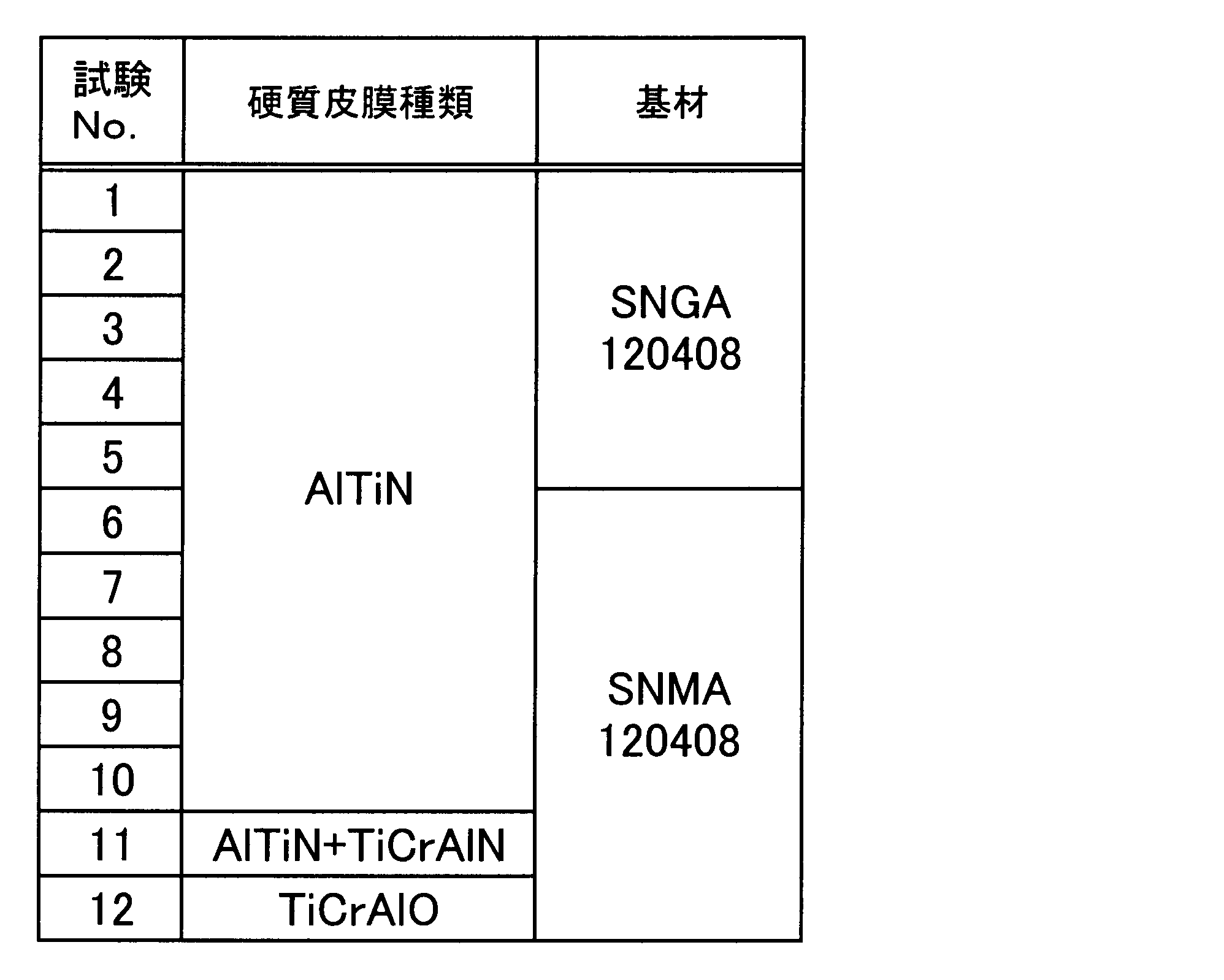
- a film having the composition and structure shown in Table 1 below was formed by an AIP apparatus having a plurality of evaporation sources.
- SNGA120408 and SNMA120408 two types of cutting inserts (manufactured by Mitsubishi Materials Corp., cemented carbide cutting tips) and mirror-finished cemented carbide specimens for surface roughness investigation (13 mm ⁇ 13 mm) ⁇ 5 mm thickness) was used.
- These substrates were ultrasonically degreased and washed in ethanol and introduced into an AIP apparatus. After exhausting the pressure in the apparatus to 5 ⁇ 10 ⁇ 3 Pa, the substrate was heated to 500 ° C., and etching with Ar ions was performed for 5 minutes. Thereafter, nitrogen gas or oxygen gas is introduced up to 4 Pa, an arc evaporation source (target diameter: 100 mm) is operated at a discharge current of 150 A, an AlTiN film, an AlTiN (base material side) + TiCrAlN (surface side) laminated film, and TiCrAlO Films were formed on the base material with a thickness of about 10 ⁇ m to form cutting tools.
- an arc evaporation source target diameter: 100 mm
- the surface parameters were measured by the following method and the wear resistance was measured.
- a projection type polishing apparatus was used to adjust the surface pressure by adjusting the projection pressure, the projection time, the particle size of the projection material, the projection direction, and the like.
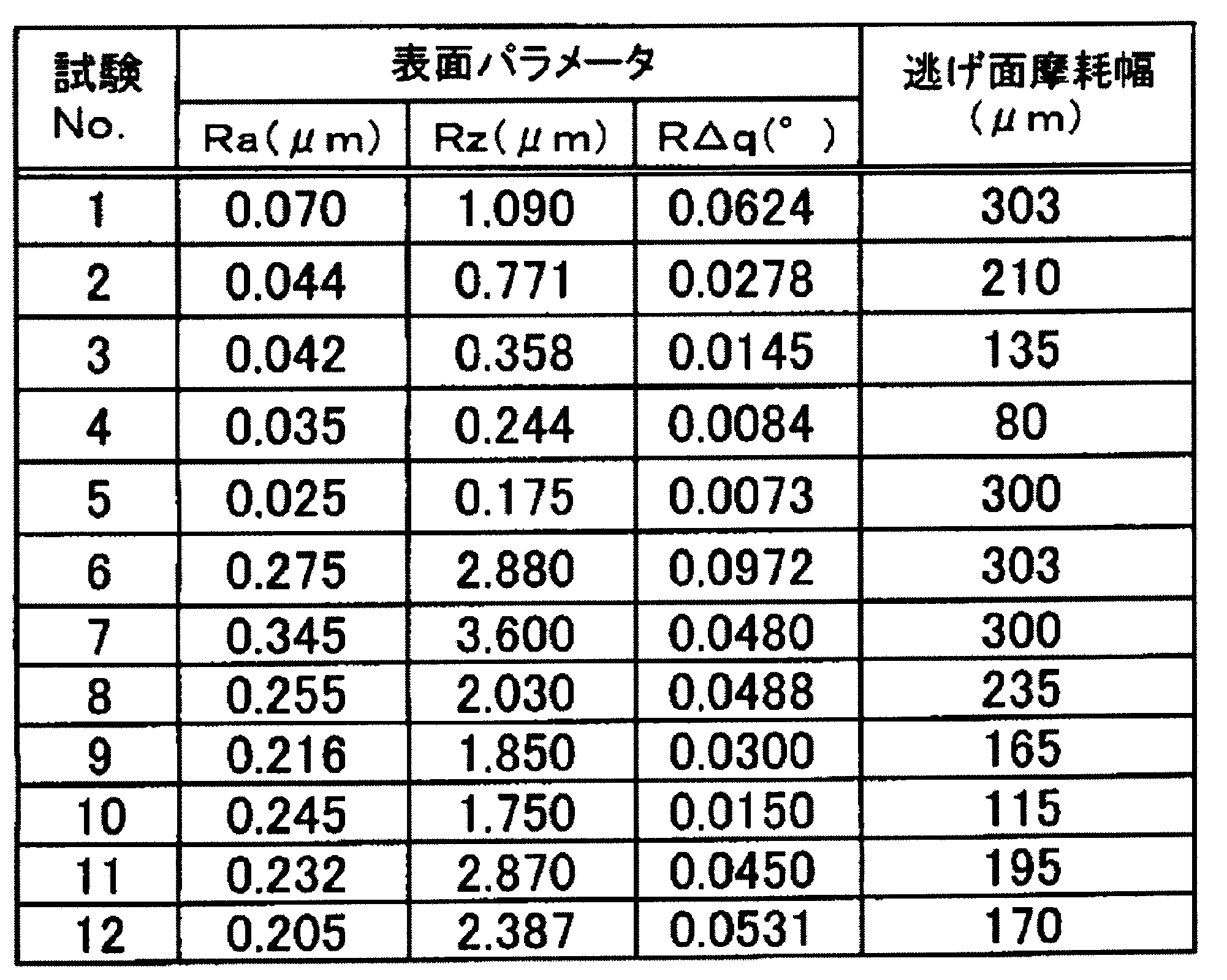
- the surface parameter was measured using a stylus type surface roughness meter (DekTak6M), and a cemented carbide specimen for surface roughness investigation was used. Performed. In this measurement, the scanning length is 1 mm, the number of measurement points in the horizontal direction is 3, and the root mean square slope from the roughness curve obtained by removing the waviness component from the measured surface curve in accordance with JIS B 0601 (2013). R ⁇ q, arithmetic average roughness Ra, and maximum height roughness Rz were calculated. This was measured at three arbitrary points on the surface, and the average value was adopted.
- the wear resistance was evaluated by measuring the flank wear width by conducting a cutting test under the following conditions using the samples (test Nos. 1 to 12) formed on the cemented carbide cutting tip. .
- a flank wear width of 300 ⁇ m or less was evaluated as having excellent wear resistance.
- the flank wear width is preferably less than 300 ⁇ m, more preferably 250 ⁇ m or less, still more preferably 200 ⁇ m or less, and even more preferably 100 ⁇ m or less.
- Test No. 2 to 4 and 8 to 12 show that the surface parameters (Ra, Rz, R ⁇ q) satisfy the range and the preferred range defined in the present invention, and therefore show good wear resistance.
- Test No. No. 5 is a range in which the root mean square slope R ⁇ q is defined by the present invention, and the wear resistance is good (the flank wear width is 300 ⁇ m), but the arithmetic average roughness Ra and the maximum height roughness This is an example in which Rz is smaller than the preferred lower limit.
- Test No. No. 7 shows that the root mean square slope R ⁇ q is within the range specified by the present invention, so that the wear resistance is good (the flank wear width is 300 ⁇ m), but the arithmetic average roughness Ra and the maximum height roughness. In this example, Rz is larger than the preferred upper limit.
Landscapes
- Chemical & Material Sciences (AREA)
- Engineering & Computer Science (AREA)
- Mechanical Engineering (AREA)
- Chemical Kinetics & Catalysis (AREA)
- Materials Engineering (AREA)
- Metallurgy (AREA)
- Organic Chemistry (AREA)
- Inorganic Chemistry (AREA)
- Cutting Tools, Boring Holders, And Turrets (AREA)
- Physical Vapour Deposition (AREA)
- Drilling Tools (AREA)
Abstract
Description
全圧力:0.5Pa以上、4Pa以下
印加電流(放電電流):100~200A
成膜時の基材温度:300℃以上、800℃以下
得られた各切削工具について(試験No.1~12)、表面パラメータの計測は、触針式の表面粗さ計(DekTak6M)を使用し、表面粗さ調査用の超硬合金製試験片を用いて行なった。この計測に際して、走査長さを1mmとし、水平方向の測定点数を3点とし、測定した表面曲線からうねり成分を除去した粗さ曲線からJIS B 0601(2013)に準拠して、二乗平均平方根傾斜RΔq、算術平均粗さRa、および最大高さ粗さRzを算出した。これを表面の任意の3点で測定し、その平均値を採用した。
耐摩耗性に関しては、上記超硬合金製切削用チップに成膜したサンプル(試験No.1~12)を用いて、下記の条件で切削試験を行ない、逃げ面摩耗幅を測定して評価した。具体的な基準として、逃げ面摩耗幅が300μm以下のものを耐摩耗性に優れると評価した。逃げ面摩耗幅は、好ましくは300μm未満であり、より好ましくは250μm以下であり、更に好ましくは200μm以下であり、より更に好ましくは100μm以下である。
被削材料:FCP500(球状黒鉛鋳鉄品:JIS G 5502(2001)):熱処理する前の状態のもの(生材)
切削速度:300m/分
送り:0.25mm/回転
切り込み深さ:2mm
潤滑:ウエット(エマルジョン)
切削時間:6分
評価条件:フランク摩耗幅(逃げ面摩耗幅)で評価
Claims (8)
- 基材表面に硬質皮膜が被覆された切削工具であって、前記硬質皮膜の表面における二乗平均平方根傾斜RΔqが0.060°以下であることを特徴とする切削工具。
- 前記硬質皮膜の表面における算術平均粗さRaが、0.030μm以上、0.30μm以下である請求項1に記載の切削工具。
- 前記硬質皮膜の表面における最大高さ粗さRzが、0.20μm以上、3.5μm以下である請求項1または2に記載の切削工具。
- 前記基材が、炭化タングステン基超硬合金、サーメット合金、高速度工具鋼、合金工具鋼のいずれかからなる請求項1または請求項2に記載の切削工具。
- 前記基材が、炭化タングステン基超硬合金、サーメット合金、高速度工具鋼、合金工具鋼のいずれかからなる請求項3に記載の切削工具。
- 前記硬質皮膜が、Ti、Cr、Alの少なくともいずれかの元素を含有する窒化物、炭窒化物または酸化物からなる請求項1または請求項2に記載の切削工具。
- 前記硬質皮膜が、Ti、Cr、Alの少なくともいずれかの元素を含有する窒化物、炭窒化物又は酸化物からなる請求項3に記載の切削工具。
- 前記硬質皮膜が、Ti、Cr、Alの少なくともいずれかの元素を含有する窒化物、炭窒化物または酸化物からなる請求項4に記載の切削工具。
Priority Applications (3)
| Application Number | Priority Date | Filing Date | Title |
|---|---|---|---|
| EP15783487.0A EP3135411A4 (en) | 2014-04-25 | 2015-04-22 | Cutting tool |
| KR1020167029206A KR20160130507A (ko) | 2014-04-25 | 2015-04-22 | 절삭 공구 |
| US15/303,301 US10265776B2 (en) | 2014-04-25 | 2015-04-22 | Cutting tool |
Applications Claiming Priority (2)
| Application Number | Priority Date | Filing Date | Title |
|---|---|---|---|
| JP2014-091848 | 2014-04-25 | ||
| JP2014091848A JP6250470B2 (ja) | 2014-04-25 | 2014-04-25 | 切削工具 |
Publications (1)
| Publication Number | Publication Date |
|---|---|
| WO2015163387A1 true WO2015163387A1 (ja) | 2015-10-29 |
Family
ID=54332549
Family Applications (1)
| Application Number | Title | Priority Date | Filing Date |
|---|---|---|---|
| PCT/JP2015/062311 Ceased WO2015163387A1 (ja) | 2014-04-25 | 2015-04-22 | 切削工具 |
Country Status (5)
| Country | Link |
|---|---|
| US (1) | US10265776B2 (ja) |
| EP (1) | EP3135411A4 (ja) |
| JP (1) | JP6250470B2 (ja) |
| KR (1) | KR20160130507A (ja) |
| WO (1) | WO2015163387A1 (ja) |
Cited By (1)
| Publication number | Priority date | Publication date | Assignee | Title |
|---|---|---|---|---|
| JP2021143883A (ja) * | 2020-03-11 | 2021-09-24 | 日鉄鋼板株式会社 | 塗装鋼板の縮み柄の評価方法 |
Families Citing this family (2)
| Publication number | Priority date | Publication date | Assignee | Title |
|---|---|---|---|---|
| JP6699836B2 (ja) | 2017-06-13 | 2020-05-27 | 住友電工ハードメタル株式会社 | ドリル |
| CN110573645B (zh) * | 2017-09-05 | 2021-08-17 | 欧瑞康表面处理解决方案股份公司普费菲孔 | 富铝的AlTiN基膜 |
Citations (5)
| Publication number | Priority date | Publication date | Assignee | Title |
|---|---|---|---|---|
| JP2006231512A (ja) * | 2005-02-25 | 2006-09-07 | Sandvik Intellectual Property Ab | 被覆切削工具インサート |
| JP2006263857A (ja) * | 2005-03-24 | 2006-10-05 | Kyocera Corp | 表面被覆切削工具およびその製造方法 |
| JP2007313636A (ja) * | 2006-04-27 | 2007-12-06 | Kyocera Corp | 切削工具およびそれを用いた被削材の切削方法 |
| JP2011183545A (ja) * | 2010-02-10 | 2011-09-22 | Hitachi Tool Engineering Ltd | 摺動特性に優れた被覆工具及びその製造方法 |
| JP2011235414A (ja) * | 2010-05-12 | 2011-11-24 | Mitsubishi Materials Corp | 硬質被覆層がすぐれた耐チッピング性を発揮する表面被覆切削工具 |
Family Cites Families (13)
| Publication number | Priority date | Publication date | Assignee | Title |
|---|---|---|---|---|
| JPH0773802B2 (ja) * | 1987-07-10 | 1995-08-09 | 住友電気工業株式会社 | 被覆超硬合金工具 |
| JP2901043B2 (ja) * | 1993-12-03 | 1999-06-02 | 神鋼コベルコツール株式会社 | 耐摩耗性・耐溶着性硬質皮膜被覆工具およびその製法 |
| ZA200007090B (en) * | 1999-12-03 | 2001-06-06 | Sumitomo Electric Industries | Coated PCBN cutting tools. |
| JP2002146515A (ja) * | 2000-11-14 | 2002-05-22 | Toshiba Tungaloy Co Ltd | 摺動性に優れる硬質膜およびその被覆工具 |
| AT410222B (de) * | 2001-04-26 | 2003-03-25 | Boehlerit Gmbh & Co Kg | Verfahren zur herstellung einer beschichtung auf einem spanenden werkzeug und zerspanungswerkzeug |
| JP4216518B2 (ja) * | 2002-03-29 | 2009-01-28 | 株式会社神戸製鋼所 | カソード放電型アークイオンプレーティング用ターゲットおよびその製造方法 |
| GB0323948D0 (en) * | 2003-10-13 | 2003-11-12 | Imp College Innovations Ltd | Wear-resisting surface structure |
| KR100576321B1 (ko) * | 2004-12-14 | 2006-05-03 | 한국야금 주식회사 | 고인성 절삭공구/내마모성 공구 |
| US7476064B2 (en) | 2006-04-27 | 2009-01-13 | Kyocera Corporation | Cutting tool and method of cutting workpiece |
| JP5424103B2 (ja) | 2008-09-24 | 2014-02-26 | 日立金属株式会社 | 塑性加工用被覆金型 |
| JP5532320B2 (ja) * | 2010-07-08 | 2014-06-25 | 住友電工ハードメタル株式会社 | 表面被覆切削工具およびその製造方法 |
| EP2700734B1 (en) | 2011-04-18 | 2018-09-12 | Kabushiki Kaisha Kobe Seiko Sho (Kobe Steel, Ltd.) | Press forming die, and method of manufacturing press forming die protection film |
| ES2677711T3 (es) * | 2011-09-28 | 2018-08-06 | Hitachi Metals, Ltd. | Elemento recubierto con excelentes propiedades de deslizamiento |
-
2014
- 2014-04-25 JP JP2014091848A patent/JP6250470B2/ja not_active Expired - Fee Related
-
2015
- 2015-04-22 EP EP15783487.0A patent/EP3135411A4/en not_active Withdrawn
- 2015-04-22 US US15/303,301 patent/US10265776B2/en not_active Expired - Fee Related
- 2015-04-22 KR KR1020167029206A patent/KR20160130507A/ko not_active Ceased
- 2015-04-22 WO PCT/JP2015/062311 patent/WO2015163387A1/ja not_active Ceased
Patent Citations (5)
| Publication number | Priority date | Publication date | Assignee | Title |
|---|---|---|---|---|
| JP2006231512A (ja) * | 2005-02-25 | 2006-09-07 | Sandvik Intellectual Property Ab | 被覆切削工具インサート |
| JP2006263857A (ja) * | 2005-03-24 | 2006-10-05 | Kyocera Corp | 表面被覆切削工具およびその製造方法 |
| JP2007313636A (ja) * | 2006-04-27 | 2007-12-06 | Kyocera Corp | 切削工具およびそれを用いた被削材の切削方法 |
| JP2011183545A (ja) * | 2010-02-10 | 2011-09-22 | Hitachi Tool Engineering Ltd | 摺動特性に優れた被覆工具及びその製造方法 |
| JP2011235414A (ja) * | 2010-05-12 | 2011-11-24 | Mitsubishi Materials Corp | 硬質被覆層がすぐれた耐チッピング性を発揮する表面被覆切削工具 |
Non-Patent Citations (1)
| Title |
|---|
| See also references of EP3135411A4 * |
Cited By (2)
| Publication number | Priority date | Publication date | Assignee | Title |
|---|---|---|---|---|
| JP2021143883A (ja) * | 2020-03-11 | 2021-09-24 | 日鉄鋼板株式会社 | 塗装鋼板の縮み柄の評価方法 |
| JP7366807B2 (ja) | 2020-03-11 | 2023-10-23 | 日鉄鋼板株式会社 | 塗装鋼板の縮み柄の評価方法 |
Also Published As
| Publication number | Publication date |
|---|---|
| US10265776B2 (en) | 2019-04-23 |
| JP2015208808A (ja) | 2015-11-24 |
| EP3135411A4 (en) | 2017-11-01 |
| JP6250470B2 (ja) | 2017-12-20 |
| US20170036274A1 (en) | 2017-02-09 |
| KR20160130507A (ko) | 2016-11-11 |
| EP3135411A1 (en) | 2017-03-01 |
Similar Documents
| Publication | Publication Date | Title |
|---|---|---|
| CN107636190B (zh) | 具有多层电弧pvd涂层的刀具 | |
| Jianxin et al. | Dry sliding wear behavior of PVD TiN, Ti55Al45N, and Ti35Al65N coatings at temperatures up to 600 C | |
| CN108883481B (zh) | 包覆切削工具 | |
| CN104508171A (zh) | 特别是通过干法机械加工操作呈现月牙洼磨损降低的高性能刀具 | |
| JP6525310B2 (ja) | 被覆工具 | |
| CN100510160C (zh) | 硬质保护膜及其形成方法、以及硬质保护膜包覆工具 | |
| JP6337944B2 (ja) | 被覆工具 | |
| CN111511490A (zh) | 包覆切削工具 | |
| CN110691662A (zh) | 包覆切削工具 | |
| Fujii et al. | Dry machining of metal using an engraving cutter coated with a droplet-free ta-C film prepared via a T-shape filtered arc deposition | |
| WO2015199102A1 (ja) | 積層型硬質皮膜および切削工具 | |
| JP3394021B2 (ja) | 被覆切削工具 | |
| Hosokawa et al. | Cutting characteristics of PVD-coated tools deposited by filtered arc deposition (FAD) method | |
| JP6250470B2 (ja) | 切削工具 | |
| KR20170137162A (ko) | 경질 피막 및 경질 피막 피복 부재 | |
| JP4331807B2 (ja) | 耐摩耗性に優れた硬質皮膜および硬質皮膜被覆部材 | |
| JP5995091B2 (ja) | 付着強度と耐チッピング性にすぐれた表面被覆切削工具 | |
| JP6273161B2 (ja) | 耐摩耗性に優れた積層皮膜 | |
| JP5502677B2 (ja) | 潤滑特性に優れた金属塑性加工用工具およびその製造方法 | |
| JP4353949B2 (ja) | 被覆部材 | |
| JP4350822B2 (ja) | 耐摩耗性に優れた硬質皮膜および硬質皮膜被覆部材 | |
| KR101727420B1 (ko) | 내마모성이 우수한 적층 피막 | |
| JP4936703B2 (ja) | 表面被覆切削工具 | |
| JP2007084899A (ja) | 被覆部材、被覆部材の被覆方法 | |
| JP3836640B2 (ja) | 耐摩耗性に優れた硬質皮膜および硬質皮膜被覆部材 |
Legal Events
| Date | Code | Title | Description |
|---|---|---|---|
| 121 | Ep: the epo has been informed by wipo that ep was designated in this application |
Ref document number: 15783487 Country of ref document: EP Kind code of ref document: A1 |
|
| REEP | Request for entry into the european phase |
Ref document number: 2015783487 Country of ref document: EP |
|
| WWE | Wipo information: entry into national phase |
Ref document number: 2015783487 Country of ref document: EP |
|
| WWE | Wipo information: entry into national phase |
Ref document number: 15303301 Country of ref document: US |
|
| ENP | Entry into the national phase |
Ref document number: 20167029206 Country of ref document: KR Kind code of ref document: A |
|
| NENP | Non-entry into the national phase |
Ref country code: DE |