WO2015165302A1 - 一种用于车辆的整体式转向驱动桥和电动车辆 - Google Patents
一种用于车辆的整体式转向驱动桥和电动车辆 Download PDFInfo
- Publication number
- WO2015165302A1 WO2015165302A1 PCT/CN2015/073714 CN2015073714W WO2015165302A1 WO 2015165302 A1 WO2015165302 A1 WO 2015165302A1 CN 2015073714 W CN2015073714 W CN 2015073714W WO 2015165302 A1 WO2015165302 A1 WO 2015165302A1
- Authority
- WO
- WIPO (PCT)
- Prior art keywords
- drive
- steering
- motor
- drive motor
- corresponding wheel
- Prior art date
- Legal status (The legal status is an assumption and is not a legal conclusion. Google has not performed a legal analysis and makes no representation as to the accuracy of the status listed.)
- Ceased
Links
Images



Classifications
-
- B—PERFORMING OPERATIONS; TRANSPORTING
- B60—VEHICLES IN GENERAL
- B60K—ARRANGEMENT OR MOUNTING OF PROPULSION UNITS OR OF TRANSMISSIONS IN VEHICLES; ARRANGEMENT OR MOUNTING OF PLURAL DIVERSE PRIME-MOVERS IN VEHICLES; AUXILIARY DRIVES FOR VEHICLES; INSTRUMENTATION OR DASHBOARDS FOR VEHICLES; ARRANGEMENTS IN CONNECTION WITH COOLING, AIR INTAKE, GAS EXHAUST OR FUEL SUPPLY OF PROPULSION UNITS IN VEHICLES
- B60K17/00—Arrangement or mounting of transmissions in vehicles
- B60K17/04—Arrangement or mounting of transmissions in vehicles characterised by arrangement, location or kind of gearing
- B60K17/14—Arrangement or mounting of transmissions in vehicles characterised by arrangement, location or kind of gearing the motor of fluid or electric gearing being disposed in, or adjacent to, traction wheel
-
- B—PERFORMING OPERATIONS; TRANSPORTING
- B60—VEHICLES IN GENERAL
- B60K—ARRANGEMENT OR MOUNTING OF PROPULSION UNITS OR OF TRANSMISSIONS IN VEHICLES; ARRANGEMENT OR MOUNTING OF PLURAL DIVERSE PRIME-MOVERS IN VEHICLES; AUXILIARY DRIVES FOR VEHICLES; INSTRUMENTATION OR DASHBOARDS FOR VEHICLES; ARRANGEMENTS IN CONNECTION WITH COOLING, AIR INTAKE, GAS EXHAUST OR FUEL SUPPLY OF PROPULSION UNITS IN VEHICLES
- B60K7/00—Disposition of motor in, or adjacent to, traction wheel
- B60K7/0007—Disposition of motor in, or adjacent to, traction wheel the motor being electric
-
- B—PERFORMING OPERATIONS; TRANSPORTING
- B60—VEHICLES IN GENERAL
- B60K—ARRANGEMENT OR MOUNTING OF PROPULSION UNITS OR OF TRANSMISSIONS IN VEHICLES; ARRANGEMENT OR MOUNTING OF PLURAL DIVERSE PRIME-MOVERS IN VEHICLES; AUXILIARY DRIVES FOR VEHICLES; INSTRUMENTATION OR DASHBOARDS FOR VEHICLES; ARRANGEMENTS IN CONNECTION WITH COOLING, AIR INTAKE, GAS EXHAUST OR FUEL SUPPLY OF PROPULSION UNITS IN VEHICLES
- B60K1/00—Arrangement or mounting of electrical propulsion units
- B60K1/02—Arrangement or mounting of electrical propulsion units comprising more than one electric motor
-
- B—PERFORMING OPERATIONS; TRANSPORTING
- B60—VEHICLES IN GENERAL
- B60K—ARRANGEMENT OR MOUNTING OF PROPULSION UNITS OR OF TRANSMISSIONS IN VEHICLES; ARRANGEMENT OR MOUNTING OF PLURAL DIVERSE PRIME-MOVERS IN VEHICLES; AUXILIARY DRIVES FOR VEHICLES; INSTRUMENTATION OR DASHBOARDS FOR VEHICLES; ARRANGEMENTS IN CONNECTION WITH COOLING, AIR INTAKE, GAS EXHAUST OR FUEL SUPPLY OF PROPULSION UNITS IN VEHICLES
- B60K17/00—Arrangement or mounting of transmissions in vehicles
- B60K17/04—Arrangement or mounting of transmissions in vehicles characterised by arrangement, location or kind of gearing
- B60K17/043—Transmission unit disposed in on near the vehicle wheel, or between the differential gear unit and the wheel
-
- B—PERFORMING OPERATIONS; TRANSPORTING
- B60—VEHICLES IN GENERAL
- B60K—ARRANGEMENT OR MOUNTING OF PROPULSION UNITS OR OF TRANSMISSIONS IN VEHICLES; ARRANGEMENT OR MOUNTING OF PLURAL DIVERSE PRIME-MOVERS IN VEHICLES; AUXILIARY DRIVES FOR VEHICLES; INSTRUMENTATION OR DASHBOARDS FOR VEHICLES; ARRANGEMENTS IN CONNECTION WITH COOLING, AIR INTAKE, GAS EXHAUST OR FUEL SUPPLY OF PROPULSION UNITS IN VEHICLES
- B60K17/00—Arrangement or mounting of transmissions in vehicles
- B60K17/04—Arrangement or mounting of transmissions in vehicles characterised by arrangement, location or kind of gearing
- B60K17/06—Arrangement or mounting of transmissions in vehicles characterised by arrangement, location or kind of gearing of change-speed gearing
- B60K17/08—Arrangement or mounting of transmissions in vehicles characterised by arrangement, location or kind of gearing of change-speed gearing of mechanical type
-
- B—PERFORMING OPERATIONS; TRANSPORTING
- B60—VEHICLES IN GENERAL
- B60K—ARRANGEMENT OR MOUNTING OF PROPULSION UNITS OR OF TRANSMISSIONS IN VEHICLES; ARRANGEMENT OR MOUNTING OF PLURAL DIVERSE PRIME-MOVERS IN VEHICLES; AUXILIARY DRIVES FOR VEHICLES; INSTRUMENTATION OR DASHBOARDS FOR VEHICLES; ARRANGEMENTS IN CONNECTION WITH COOLING, AIR INTAKE, GAS EXHAUST OR FUEL SUPPLY OF PROPULSION UNITS IN VEHICLES
- B60K17/00—Arrangement or mounting of transmissions in vehicles
- B60K17/30—Arrangement or mounting of transmissions in vehicles the ultimate propulsive elements, e.g. ground wheels, being steerable
-
- B—PERFORMING OPERATIONS; TRANSPORTING
- B60—VEHICLES IN GENERAL
- B60K—ARRANGEMENT OR MOUNTING OF PROPULSION UNITS OR OF TRANSMISSIONS IN VEHICLES; ARRANGEMENT OR MOUNTING OF PLURAL DIVERSE PRIME-MOVERS IN VEHICLES; AUXILIARY DRIVES FOR VEHICLES; INSTRUMENTATION OR DASHBOARDS FOR VEHICLES; ARRANGEMENTS IN CONNECTION WITH COOLING, AIR INTAKE, GAS EXHAUST OR FUEL SUPPLY OF PROPULSION UNITS IN VEHICLES
- B60K17/00—Arrangement or mounting of transmissions in vehicles
- B60K17/30—Arrangement or mounting of transmissions in vehicles the ultimate propulsive elements, e.g. ground wheels, being steerable
- B60K17/306—Arrangement or mounting of transmissions in vehicles the ultimate propulsive elements, e.g. ground wheels, being steerable with a universal joint in the axis of the steering knuckle
-
- Y—GENERAL TAGGING OF NEW TECHNOLOGICAL DEVELOPMENTS; GENERAL TAGGING OF CROSS-SECTIONAL TECHNOLOGIES SPANNING OVER SEVERAL SECTIONS OF THE IPC; TECHNICAL SUBJECTS COVERED BY FORMER USPC CROSS-REFERENCE ART COLLECTIONS [XRACs] AND DIGESTS
- Y02—TECHNOLOGIES OR APPLICATIONS FOR MITIGATION OR ADAPTATION AGAINST CLIMATE CHANGE
- Y02T—CLIMATE CHANGE MITIGATION TECHNOLOGIES RELATED TO TRANSPORTATION
- Y02T10/00—Road transport of goods or passengers
- Y02T10/60—Other road transportation technologies with climate change mitigation effect
- Y02T10/72—Electric energy management in electromobility
Definitions
- the present invention relates to the electric vehicle industry, and more particularly to an integral steering axle and an electric vehicle.
- Existing electric vehicles typically have two transaxles, each for driving a pair of wheels on either side of the vehicle.
- Each of the transaxles accepts a driving force from a drive motor disposed at the front or rear of the vehicle.
- the electric vehicle can implement a front drive, a rear drive or a four drive depending on the number and position of the drive axles driven by the drive motor.
- the chassis For vehicles with a large carrying capacity, such as large or heavy passenger cars or trucks, the chassis usually has more drive axles, for example generally consisting of four axles, six axles or eight axles.
- the driving structure of such a vehicle is complicated, and it is difficult to implement the corresponding eight-wheel drive, twelve-drive or six-drive.
- a power system of a series hybrid vehicle is provided in Chinese Patent Application No. 201310467918.2, to which the applicant has filed.
- the power system allows the use of alternative fuels with lower energy density instead of conventional gasoline or diesel, and allows the engine in the auxiliary power unit to operate in areas with low fuel consumption and low emissions, effectively reducing emissions and improving emissions.
- the fuel economy makes up for the relatively low energy conversion efficiency of the series hybrid vehicle power system.
- the power system can flexibly set an appropriate number of engines for combination use as needed. Thus, by using a sufficient number of engines in combination, it is possible to provide sufficient power with a low-cost fuel sufficient for a large-capacity vehicle such as a truck, thereby providing a possibility for such a vehicle to be electrically driven.
- a drive motor is used to drive the wheels on both sides of one axle, which is not conducive to the flexibility of electric vehicle control.
- Existing electric vehicles also have a hub motor, but they are costly and are currently only used for small-capacity vehicles such as family vehicles due to limitations in the power provided.
- an integral steering axle for a vehicle for mounting two wheels on each side thereof and driving the wheels for rotation and steering, including: a generally rigid bridge, It can be arranged to extend between the two wheels in the transverse direction of the vehicle; two sets of motor drive systems mounted at the bridge, each set of motor drive systems being capable of independently driving the two of the wheels A corresponding wheel rotates and turns.
- Each set of motor drive systems includes: a first drive motor disposed separately from the corresponding wheel; a first transmission mechanism disposed between the first drive motor and the corresponding wheel for using the first drive An output power of the motor is transmitted to the corresponding wheel to drive the corresponding wheel to rotate; and a second drive motor is provided to provide the corresponding wheel with steering power required for steering.
- the first transmission mechanism includes: a speed reducer for transmitting output power of the first driving motor, and outputting a reduced rotation speed compared to a rotation speed of a rotating shaft of the first driving motor.
- the first drive motor is arranged such that a rotational axis of its rotational axis extends in a lateral direction of the vehicle.
- the first transmission mechanism of the vehicle further includes: a half shaft for transmitting output power of the first driving motor to the corresponding wheel; wherein all or a part of the half shaft is configured to be capable of The steering of the wheel oscillates.
- axle shaft includes a first portion and a second portion that are connected via a universal joint drive; wherein the first portion is configured to be swingable with steering of the wheel, and the second portion is configured by the first The rotating shaft of the drive motor is formed.
- each motor drive system further includes a second transmission mechanism installed at the bridge, the second transmission mechanism being disposed between the second drive motor and the corresponding wheel for the second drive The output power of the motor is transmitted to the corresponding wheel to drive the corresponding wheel for steering.
- the bridge is formed in the form of a hollow axle housing.
- the first driving motor is disposed inside the hollow axle housing
- the second driving motor is also disposed inside the hollow axle housing;
- At least a portion of the first transmission mechanism is also disposed inside the hollow axle housing.
- an electric vehicle including a plurality of axles, at least one of which is the aforementioned integral steering axle.
- each of the plurality of axles employs the integral steering axle.
- the number of the plurality of axles is at least three, and optionally, the number of the plurality of axles is at least four.
- the invention installs two sets of motor drive systems independently driving the two sides of the wheel on the integral steering drive axle, respectively for controlling the steering and rotation of the corresponding wheel, thereby improving the control flexibility of the vehicle and realizing independent driving of each wheel and Independent steering.
- the integral steering axle of the present invention is particularly suitable for use in large carrying vehicles such as large or heavy passenger cars or vans.
- the integral steering axle is also particularly suitable for retrofitting an existing fuel-engine powered axle into a motor-driven axle.
- the motor drive system for driving the corresponding wheel of the present invention adopts a pre-assembled manner to form a modular structure with the bridge, which facilitates and simplifies the axle installation of the vehicle.
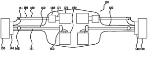
- FIG. 1 is a schematic structural view of an integrated steering axle according to an embodiment of the present invention.
- FIG. 2 is a schematic structural view of an integral steering axle according to an embodiment of the present invention, wherein the bridge is a hollow casing;
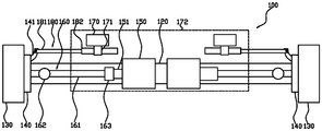
- FIG. 3 is a schematic structural view of an integral steering axle according to an embodiment of the present invention, in which only a first driving motor and a first transmission system are installed in a bridge of a hollow axle housing;
- FIG. 4 is a schematic structural view of an integral steering axle according to an embodiment of the present invention, wherein a motor drive system is mounted on a rigid solid bridge;
- Fig. 5 is a structural schematic view showing the rotation axis of the first drive motor and the torque direction of the corresponding wheel in one embodiment of the present invention.
- FIGS 1-5 illustrate structural views of various embodiments of an integrated steering axle 100 in accordance with the present invention, respectively.
- the integral steering axle 100 is generally used to mount two wheels 130 on each side thereof and drive the wheels 130 for rotation and steering. It should be noted that it is shown in the drawing The resulting wheel 130 is only its hub portion.
- the integrated steering axle 100 can include a generally rigid bridge 120 that can be arranged to extend between two wheels 130 in the transverse direction of the vehicle. Two sets of motor drive systems 110 can be mounted at the bridge 120, and each set of motor drive systems 110 can independently drive one of the two wheels 130 for rotation and steering.
- Each set of motor drive systems 110 is disposed adjacent its corresponding wheel 130 and may include a first drive motor 150, a first drive mechanism 160, and a second drive motor 170.
- the first drive motor 150 is disposed separately from the corresponding wheel 130, that is, any part of the first drive motor 150 does not belong to the wheel 130, which is significantly different from the prior art hub motor, but can be conventional.
- the first transmission mechanism 160 may be disposed between the first driving motor 150 and the corresponding wheel 130 for transmitting the output power of the first driving motor 150 to the corresponding wheel 130 to drive the corresponding wheel 130 to rotate, thereby causing the vehicle to advance or Back.
- the second drive motor 170 can provide the corresponding wheel 130 with the steering power required to make the steering to drive the wheel 130 to deflect relative to the direction of travel of the vehicle.
- the integrated steering axle 100 integrates two sets of motor drive systems 110 on one axle for steering and rotation of two corresponding wheels 130, respectively.
- the two sets of motor drive systems 110 can operate independently of one another to achieve independent control of the two corresponding wheels 130 such that the two wheels 130 can each independently rotate and steer.
- the first transmission mechanism 160 may also include a speed reducer 163 for transmitting the output power of the first drive motor 150.
- the speed reducer 163 can output a reduced rotational speed compared to the rotational speed of the rotational shaft 151 of the first drive motor 150 to increase the torque while reducing the rotational speed.
- the first drive motor 150 is arranged such that the axis of rotation of its axis of rotation 151 extends in the lateral direction of the vehicle, that is, substantially parallel to the bridge 120.
- the torque output direction of the rotation shaft 151 of the first drive motor 150 is the same as the torque direction required to drive the rotation of the corresponding wheel 130, so that the rotation shaft of the first drive motor 150 can be not changed by the speed reducer 163.
- the speed reducer 163 only assumes the effect of reducing the rotational speed, which can be realized simply by a reduction gear set composed of a plurality of parallel gears.
- the first drive motor 150 thus arranged facilitates reducing the overall lateral dimension of the integral steering axle 100.
- the rotating shaft 151 of the first driving motor 150 is coaxially arranged with a half shaft 161 to be described later.
- the first driving motor 150 The rotating shaft 151 is parallel to the half shaft 161 but is arranged in a staggered manner, and the torque is converted by the speed reducer 163 in the middle.
- the first drive motor 150 is arranged such that the axis of rotation of its axis of rotation 151 extends in the longitudinal direction of the vehicle, which is similar to the longitudinal drive commonly found in the drive trains of existing vehicles.
- the speed reducer 163 may adopt a structure similar to that of the existing speed reducer, for example, by a bevel gear pair that is vertically arranged to each other.
- the speed reducer 163 can directly transmit the torque of the rotating shaft 151 of the first drive motor 150, and can also change the direction of the torque.
- the first drive motor 150 thus arranged is more advantageous for retrofitting existing axles.
- the first transmission mechanism 160 may also include a half shaft 161 for transmitting the output power of the first drive motor 150 to the corresponding wheel 130.
- the half shaft 161 may have a substantially similar structure to the half shaft of the existing vehicle, but it is apparent that in the present invention, since each of the half shafts 161 is directly driven by a first drive motor 150 disposed in the vicinity thereof, A drive shaft is used to drive the two opposite half shafts as in the prior art, so that by arranging the position of the first drive motor 150 closer to the corresponding wheel 130, the length of the half shaft 161 can be made longer than Some conventional half shafts are shorter in length.
- the half shaft 161 can include a first portion and a second portion that are drivingly coupled by a universal joint 162 (typically a constant velocity joint).
- a universal joint 162 typically a constant velocity joint
- the first portion and the second portion are respectively a half shaft 161.
- the first portion of the half shaft 161 is configured to be swingable with the steering of the corresponding wheel 130, while the second portion of the half shaft 161 can be held to be only rotatable.
- the specific half-shaft structure can also refer to the semi-axle structure of the fuel-powered steering axle in the prior art.
- the rotational shaft 151 of the first drive motor 150 is coaxially arranged with the half shaft 161 to be described later, in which case, although not shown in the drawings It is shown, but it is contemplated that the rotational axis 151 of the first drive motor 150 may extend further toward the universal joint 162, or may even be formed directly or as the half shaft of the rotational shaft 151 of the first drive motor 150.
- the half shaft 161 is formed only by the left side portion of the universal joint 162, so that the entire half shaft 161 is disposed to be swingable corresponding to the steering of the corresponding wheel 130.
- the motor drive system 110 can also include a second transmission mechanism 180 mounted at the bridge 120.
- the second transmission mechanism 180 is disposed between the second driving motor 170 and the corresponding wheel 130 for transmitting the output power of the second driving motor 170 to the corresponding wheel 130 to drive the knuckle 140 of the corresponding wheel 130 to push the corresponding wheel 130. Make a turn.
- the second transmission mechanism 180 can include a diverter 182 and a steering rod 181.
- the diverter 182 can convert the rotation of the rotating shaft 171 of the second drive motor 170 into a linear motion of the steering lever 181 to pull the lever arm 141 of the knuckle 140 at the corresponding wheel 130 such that the corresponding wheel 130 is steered.
- the rotation shaft 171 of the second drive motor 170 extends in a direction substantially parallel to the bridge 120 or the steering lever 181.
- the rotation shaft 171 of the second drive motor 170 extends in a direction perpendicular to the bridge 120 or the steering lever 181.
- the structure of the concrete diverter 182 may employ a suitable diverter structure of the prior art depending on the arrangement direction of the second drive motor 170. Particularly in the case of Fig. 4, the diverter 182 can conveniently employ the prior art steering gear structure consisting of a gear and a rack.
- the steering gear 182 may additionally provide a speed reduction mechanism such as a reduction gear set.
- the bridge 120 can be formed in the form of a hollow axle housing for placing several components of the integral steering axle 100 within the interior of the hollow axle housing.
- both sets of motor drive systems 110 are mounted within a bridge 120 having a hollow axle housing.
- the first drive motor 150, the first transmission mechanism 160, the second drive motor 170, and the second transmission mechanism 180 may be connected in advance and installed in the bridge 120.
- the first drive motor 150 and the first transmission system 160 are mounted within a hollow axle housing formed by a bridge.
- the second drive motor 170 For other components not installed in the bridge 120, such as the second drive motor 170, the steering 182, etc., it may be mounted at a mounting bracket 172 (shown schematically by a broken line) fixed outside the bridge 120, and The mounting bracket 172 is held.
- the mounting bracket 172 can also be formed in a substantially closed housing shape.
- the entire steering axle 110 can be made more suitable to form a pre-assembled modular component.
- the integral steering axle 100 can be mounted to the vehicle as a unit.
- some shapes of the bridge 120 in the form of a hollow axle housing are shown in FIGS. 2 to 3, it is merely illustrative, and in practice, the specific shape of the hollow axle housing may be based on the position and shape of the components therein. The design is carried out, for example, the surface of the axle housing is designed to conform to the overall contour of all the components therein to form a bridge shell in a compact form.
- the two sets of motor drive systems 110 can be fixedly mounted external to the solid bridge 120.
- a mounting bracket 172 (shown schematically by a dashed line) secured to the outside of the bridge 120 can be utilized to facilitate the mounting and retention of the various components.
- the mounting bracket 172 can also be formed in a substantially closed housing shape to enclose the two sets of motor drive systems 110.
- the present invention also provides an electric vehicle including a plurality of axles, at least one of which is the integral steering axle 100 described above. Further, each of all of the axles in the electric vehicle employs the integral steering axle 110 described above.
- the integrated steering axle 100 of the present invention is also particularly well suited for use in large capacity electric vehicles, such as large or heavy duty electric passenger cars or vans. In this case, the electric vehicle may have more axles, for example at least 3 or even at least 4 axles, each of which may employ the integral steering axle 100 according to the invention.
- the front, middle and rear axles of an electric vehicle can be used with the integral steering drive.
- Bridge 100, the axle between adjacent two integral steering axles employs axle structures in other existing vehicles, such as axles in which passive wheels are installed.
- the integral steering axle 100 of the present invention can be easily implemented based on an existing fuel-engine-driven integral axle structure.
- the specific wheel rotation and steering structure can directly utilize the structure in the existing vehicle, and then replace the drive shaft and the steering motor in the existing vehicle with the respective first drive motor 150 and second drive motor 170, respectively. Further, after the first drive motor 150 and the second drive motor 170 are independently controlled to control the corresponding wheel, the differential used in the axle of the existing vehicle can also be eliminated.
Landscapes
- Engineering & Computer Science (AREA)
- Chemical & Material Sciences (AREA)
- Combustion & Propulsion (AREA)
- Transportation (AREA)
- Mechanical Engineering (AREA)
- Arrangement Or Mounting Of Propulsion Units For Vehicles (AREA)
- Power Steering Mechanism (AREA)
- Arrangement Of Transmissions (AREA)
- Motor Power Transmission Devices (AREA)
- Arrangement And Driving Of Transmission Devices (AREA)
- Electric Propulsion And Braking For Vehicles (AREA)
Abstract
Description
Claims (10)
- 一种用于车辆的整体式转向驱动桥,用于在其两侧分别安装两个车轮并驱动所述车轮进行转动和转向,包括:整体为刚性的桥梁,其能够布置成沿所述车辆的横向在所述两个车轮之间延伸;安装在所述桥梁处的两组电机驱动系统,每一组电机驱动系统能够独立地驱动所述两个车轮中的一个对应车轮进行转动和转向;其中,每一组电机驱动系统包括:与所述对应车轮分立布置的第一驱动电机;第一传动机构,布置在所述第一驱动电机与所述对应车轮之间,用于将所述第一驱动电机的输出动力传递至所述对应车轮,以驱动所述对应车轮进行转动;和第二驱动电机,用于向所述对应车轮提供进行转向所需的转向动力。
- 根据权利要求1所述的整体式转向驱动桥,其中,所述第一传动机构包括:减速器,用于传递所述第一驱动电机的输出动力,并且相比于所述第一驱动电机的转动轴的转速输出一降低的转速。
- 根据权利要求1或2所述的整体式转向驱动桥,其中,所述第一驱动电机布置成其转动轴的转动轴线沿所述车辆的横向延伸。
- 根据权利要求1-3中任一项所述的整体式转向驱动桥,其中,所述第一传动机构还包括:半轴,用于将所述第一驱动电机的输出动力传递到所述对应车轮;其中,所述半轴的全部或者一部分设置成能够随所述车轮的转向进行摆动。
- 根据权利要求4所述的整体式转向驱动桥,其中,所述半轴包括经由万向节传动连接的第一部分和第二部分;其中,所述第一部分设置成能够随所述车轮的转向进行摆动,所述第二部分由所述第一驱动电机的所述转动轴形成。
- 根据权利要求1-5中任一项所述的整体式转向驱动桥,其中,每一电机驱动系统还包括安装在所述桥梁处的第二传动机构,所述第二传动机构设置在所述第二驱动电机与对应车轮之间,用于将所述第二驱动电机的输出动力传递至所述对应车轮,以驱动所述对应车轮进行转向。
- 如权利要求1-6任一项所述的整体式转向驱动桥,其中,所述桥梁形成 为空心桥壳的形式,所述第一驱动电机布置在所述空心桥壳的内部;可选地,所述第二驱动电机也布置在所述空心桥壳的内部;进一步可选地,所述第一传动机构的至少一部分也布置在所述空心桥壳的内部。
- 一种电动车辆,其中,包括多个车桥,所述多个车桥中的至少一个为根据权利要求1-7中任一项所述的整体式转向驱动桥。
- 如权利要求8所述的电动车辆,其中,所述多个车桥中的每一个都采用所述整体式转向驱动桥。
- 如权利要求8或9所述的电动车辆,其中,所述多个车桥的数量至少为3个,可选地,所述多个车桥的数量至少为4个。
Priority Applications (5)
| Application Number | Priority Date | Filing Date | Title |
|---|---|---|---|
| EP15786439.8A EP3138718B1 (en) | 2014-04-29 | 2015-03-05 | Integrated steering drive axle for vehicle and electric vehicle |
| PL15786439T PL3138718T3 (pl) | 2014-04-29 | 2015-03-05 | Zintegrowana sterująca oś napędowa dla pojazdu i pojazdu elektrycznego |
| JP2016564250A JP6279102B2 (ja) | 2014-04-29 | 2015-03-05 | 自動車用統合操舵駆動軸及び電気自動車 |
| US15/307,547 US10071627B2 (en) | 2014-04-29 | 2015-03-05 | Integrated steering drive axle for vehicle and electric vehicle |
| ES15786439.8T ES2674161T3 (es) | 2014-04-29 | 2015-03-05 | Eje motor de dirección integrado para vehículo y vehículo eléctrico |
Applications Claiming Priority (2)
| Application Number | Priority Date | Filing Date | Title |
|---|---|---|---|
| CN201410179348.1A CN103963637B (zh) | 2014-04-29 | 2014-04-29 | 一种用于车辆的整体式转向驱动桥和电动车辆 |
| CN201410179348.1 | 2014-04-29 |
Publications (1)
| Publication Number | Publication Date |
|---|---|
| WO2015165302A1 true WO2015165302A1 (zh) | 2015-11-05 |
Family
ID=51233820
Family Applications (1)
| Application Number | Title | Priority Date | Filing Date |
|---|---|---|---|
| PCT/CN2015/073714 Ceased WO2015165302A1 (zh) | 2014-04-29 | 2015-03-05 | 一种用于车辆的整体式转向驱动桥和电动车辆 |
Country Status (9)
| Country | Link |
|---|---|
| US (1) | US10071627B2 (zh) |
| EP (1) | EP3138718B1 (zh) |
| JP (1) | JP6279102B2 (zh) |
| CN (1) | CN103963637B (zh) |
| ES (1) | ES2674161T3 (zh) |
| HU (1) | HUE037780T2 (zh) |
| PL (1) | PL3138718T3 (zh) |
| TR (1) | TR201808711T4 (zh) |
| WO (1) | WO2015165302A1 (zh) |
Cited By (5)
| Publication number | Priority date | Publication date | Assignee | Title |
|---|---|---|---|---|
| CN106864252A (zh) * | 2017-04-17 | 2017-06-20 | 吉林大学 | 一种转向与驱动集成式轮边电驱动系统及车辆 |
| CN109466297A (zh) * | 2018-11-30 | 2019-03-15 | 汽解放汽车有限公司 | 一种中央集成式双电机双amt电驱动桥总成 |
| CN109466299A (zh) * | 2018-11-30 | 2019-03-15 | 汽解放汽车有限公司 | 一种轻量化双电机双减速器电驱动桥总成 |
| US20230202561A1 (en) * | 2021-12-29 | 2023-06-29 | Wrightspeed, Inc. | Independent wheel shiftable wheel drives |
| CN117656802A (zh) * | 2020-11-30 | 2024-03-08 | 比亚迪股份有限公司 | 轮边驱动总成和车辆 |
Families Citing this family (38)
| Publication number | Priority date | Publication date | Assignee | Title |
|---|---|---|---|---|
| CN103963637B (zh) | 2014-04-29 | 2017-08-25 | 浙江吉利控股集团有限公司 | 一种用于车辆的整体式转向驱动桥和电动车辆 |
| CN105799491A (zh) * | 2014-12-31 | 2016-07-27 | 长春孔辉汽车科技股份有限公司 | 一种新能源汽车双电动机驱动桥 |
| CN105799480A (zh) * | 2014-12-31 | 2016-07-27 | 长春孔辉汽车科技股份有限公司 | 多轴分布驱动纯电动汽车系列化平台 |
| GB201618478D0 (en) * | 2016-11-02 | 2016-12-14 | Qinetiq Ltd | Drive configuration |
| EP3333000B1 (de) * | 2016-12-08 | 2019-08-14 | Audi Ag | Achsantrieb für ein kraftfahrzeug sowie achsantriebseinrichtung |
| DE102017212500A1 (de) * | 2016-12-08 | 2018-06-14 | Audi Ag | Achsantrieb für ein Kraftfahrzeug sowie Achsantriebseinrichtung |
| CN107054072A (zh) * | 2017-01-26 | 2017-08-18 | 安徽安凯汽车股份有限公司 | 一种贯穿输入式电控变速比整体驱动系统 |
| DE102017203587A1 (de) * | 2017-03-06 | 2018-09-06 | Audi Ag | Antriebseinrichtung für ein Kraftfahrzeug und Kraftfahrzeug mit mindestens einer Antriebseinrichtung |
| CN107010105B (zh) * | 2017-04-17 | 2023-12-15 | 吉林大学 | 一种线控转向与独立驱动集成式轮边电驱动装置 |
| EP3634798B1 (de) * | 2017-06-08 | 2021-03-03 | Daimler AG | Antriebsvorrichtung für ein kraftfahrzeug, insbesondere für ein nutzfahrzeug |
| DE102017123570A1 (de) | 2017-10-10 | 2019-04-11 | Thyssenkrupp Ag | Elektrische Antriebseinheit und Kraftfahrzeug |
| JP6972896B2 (ja) * | 2017-10-18 | 2021-11-24 | スズキ株式会社 | 電気自動車の車両下部構造 |
| DE102017218868A1 (de) * | 2017-10-23 | 2019-04-25 | Audi Ag | Antriebseinrichtung |
| CN108146423B (zh) * | 2018-02-09 | 2023-07-21 | 吉林大学 | 一种转向、防倾与驱动集成式轮边电驱动系统及控制方法 |
| CN109080700A (zh) * | 2018-09-19 | 2018-12-25 | 山东金惠新达智能制造科技有限公司 | 一种四驱独立转向机构 |
| DE102018215934A1 (de) * | 2018-09-19 | 2020-03-19 | ZF Drivetech (Suzhou) Co.Ltd. | Achsantrieb |
| CN109094363B (zh) * | 2018-09-19 | 2024-04-05 | 安徽工程大学 | 一种电动车后桥驱动系统及其驱动方法 |
| CN109160455A (zh) * | 2018-11-12 | 2019-01-08 | 杭叉集团股份有限公司 | 大吨位电动叉车及其双电机驱动装置 |
| EP3873793A4 (en) | 2020-01-06 | 2023-06-14 | Workhorse Group Inc. | LAND VEHICLES WITH DETACHABLE POWER LINE UNITS, POWER LINE UNITS AND METHODS THEREOF |
| MX2021004988A (es) * | 2020-01-06 | 2021-09-08 | Workhorse Group Inc | Vehiculos terrestres que incorporan unidades de trenes de potencia extraible, unidades de trenes de potencia y sus metodos. |
| TWI803796B (zh) * | 2020-03-27 | 2023-06-01 | 吳震洋 | 車輛轉向裝置 |
| CN112895809B (zh) * | 2021-02-26 | 2022-12-06 | 苏州挚途科技有限公司 | 驱动桥驱动的方法、装置及电子设备 |
| GB2612109B (en) * | 2021-10-22 | 2024-03-27 | Jaguar Land Rover Ltd | Vehicle rear axle |
| US11440456B1 (en) | 2021-12-09 | 2022-09-13 | Workhorse Group Inc. | Land vehicles adapted for use as electric delivery vehicles |
| US11591032B1 (en) | 2021-12-09 | 2023-02-28 | Workhorse Group Inc. | Land vehicles incorporating brake systems and methods therefor |
| US11485215B1 (en) | 2021-12-09 | 2022-11-01 | Workhorse Group Inc. | Land vehicles incorporating electric motors and methods therefor |
| US11440590B1 (en) | 2021-12-09 | 2022-09-13 | Workhorse Group Inc. | Land vehicles incorporating impact management systems |
| US20240075979A1 (en) * | 2022-09-02 | 2024-03-07 | Schaeffler Technologies AG & Co. KG | Combined electric motor beam axle assembly and steering actuator |
| EP4584517A1 (en) * | 2022-09-08 | 2025-07-16 | American Axle & Manufacturing, Inc. | Electric beam axle |
| IT202300007101A1 (it) * | 2023-04-13 | 2024-10-13 | Ferrari Spa | Autoveicolo |
| IT202300007071A1 (it) * | 2023-04-13 | 2024-10-13 | Ferrari Spa | Assale ed autoveicolo comprendente tale assale |
| CN117246404B (zh) * | 2023-08-31 | 2026-03-10 | 三一专用汽车有限责任公司 | 电动转向系统和车辆 |
| CN117301836A (zh) * | 2023-10-08 | 2023-12-29 | 东风汽车集团股份有限公司 | 车辆的分布式驱动系统及驱动总成 |
| US12570363B1 (en) | 2024-09-10 | 2026-03-10 | Workhorse Group Inc. | Land vehicles incorporating reinforcement structures, seatbelt tower assemblies, and seat frame assemblies |
| US12473030B1 (en) | 2025-02-27 | 2025-11-18 | Workhorse Group Inc. | Land vehicles incorporating multi-segment chassis, multi-segment chassis, and components therefor |
| US12473029B1 (en) | 2025-02-27 | 2025-11-18 | Workhorse Group Inc. | Land vehicles incorporating front and rear suspension assemblies, suspension assemblies, and components therefor |
| US12466485B1 (en) | 2025-02-27 | 2025-11-11 | Workhorse Group Inc. | Land vehicles incorporating front and rear powertrain units, powertrain units, and components therefor |
| US12472807B1 (en) | 2025-02-27 | 2025-11-18 | Workhorse Group Inc. | Land vehicles incorporating cradles for supporting electrical devices and components therefor |
Citations (5)
| Publication number | Priority date | Publication date | Assignee | Title |
|---|---|---|---|---|
| EP0013190A1 (fr) * | 1978-12-26 | 1980-07-09 | ETAT-FRANCAIS représenté par le Délégué Général pour l' Armement | Groupe propulseur hydraulique pour véhicule à recyclage mécanique de puissance en virage |
| CN1167709A (zh) * | 1996-05-29 | 1997-12-17 | Gec阿尔斯托姆运输公司 | 具有独立转动轮的驱动桥 |
| CN201227957Y (zh) * | 2008-04-01 | 2009-04-29 | 辽宁曙光汽车集团股份有限公司 | 组合支撑结构轻型汽车整体式转向驱动桥总成 |
| CN101890908A (zh) * | 2010-07-30 | 2010-11-24 | 重庆长安汽车股份有限公司 | 一种用于电动汽车或混合动力汽车的驱动桥 |
| CN103963637A (zh) * | 2014-04-29 | 2014-08-06 | 浙江吉利控股集团有限公司 | 一种用于车辆的整体式转向驱动桥和电动车辆 |
Family Cites Families (54)
| Publication number | Priority date | Publication date | Assignee | Title |
|---|---|---|---|---|
| US4657104A (en) * | 1983-07-23 | 1987-04-14 | Cybermation, Inc. | Concentric shaft mobile base for robots and the like |
| JPS62218225A (ja) | 1986-03-20 | 1987-09-25 | Mitsubishi Heavy Ind Ltd | エレクトリツクホイ−ルドライブ装置 |
| US4741409A (en) * | 1987-06-25 | 1988-05-03 | General Motors Corporation | Electric steering system for automobiles |
| US5465806A (en) | 1989-03-31 | 1995-11-14 | Kabushiki Kaisha Shikoku Sogo Kenkyujo | Electric vehicle |
| DE4334742C2 (de) * | 1993-10-12 | 1997-04-30 | Francke Renate | Deaktivierbare Achslenkung |
| JPH09128052A (ja) * | 1995-11-02 | 1997-05-16 | Japan Tobacco Inc | 自走式搬送車 |
| DE29518401U1 (de) * | 1995-11-20 | 1997-03-20 | Siemens AG, 80333 München | Fahrwerk für Nutzfahrzeuge |
| IT1287898B1 (it) * | 1996-05-14 | 1998-08-26 | Carraro Spa | Sistema di molleggio e variabilita' di assetto di un ponte differenziale |
| AUPO344896A0 (en) * | 1996-11-05 | 1996-12-05 | Grant, Brendan Joel | Eze the modular multifunction electric vehicle |
| DE19750585A1 (de) * | 1997-11-17 | 1999-06-02 | Deutsch Zentr Luft & Raumfahrt | Aktuator zum Korrigieren eines über das Lenkrad eines Fahrzeugs an die Räder einer gelenkten Fahrzeugachse eingegebenen Lenkwinkels |
| JP4321886B2 (ja) * | 1998-05-28 | 2009-08-26 | 第一電気株式会社 | 重量物搬送車 |
| US6491127B1 (en) * | 1998-08-14 | 2002-12-10 | 3Com Corporation | Powered caster wheel module for use on omnidirectional drive systems |
| EP1304279A1 (en) * | 2000-07-14 | 2003-04-23 | TCM Corporation | Working vehicle with traversing system |
| AU2001294660A1 (en) | 2000-09-25 | 2002-04-08 | Its Bus, Inc. | Platforms for sustainable transportation |
| US7014008B2 (en) * | 2002-06-27 | 2006-03-21 | Honda Giken Kogyo Kabushiki Kaisha | Steering system for vehicle |
| JP2005205976A (ja) | 2004-01-21 | 2005-08-04 | Nissan Motor Co Ltd | 車両の駆動力伝達装置 |
| JP4285310B2 (ja) * | 2004-04-16 | 2009-06-24 | トヨタ自動車株式会社 | 車両の操舵装置 |
| US20050236208A1 (en) * | 2004-04-27 | 2005-10-27 | Richard Runkles | Power wheelchair |
| JP2005329784A (ja) * | 2004-05-19 | 2005-12-02 | Hitachi Ltd | 電動パワーステアリング装置 |
| JP4442509B2 (ja) | 2005-04-28 | 2010-03-31 | 株式会社エクォス・リサーチ | 制御装置及びその制御装置を備える車両 |
| JP4853070B2 (ja) | 2005-05-26 | 2012-01-11 | 日本精工株式会社 | ステアバイワイヤシステム |
| US20060278466A1 (en) * | 2005-06-13 | 2006-12-14 | Bo Cheng | Electric power steering systems |
| US20080120974A1 (en) * | 2006-11-24 | 2008-05-29 | Parker-Hannifin Corporation | Integrated hydrostatic transmission for left and right wheel drive |
| FR2898833B1 (fr) * | 2006-03-23 | 2008-12-05 | Conception & Dev Michelin Sa | Liaison au sol pour vehicule |
| US7418328B2 (en) * | 2006-05-08 | 2008-08-26 | Deere & Company | Steering logic for self-propelled mower |
| WO2008048477A2 (en) * | 2006-10-13 | 2008-04-24 | The Ohio State University Research Foundation | Powertrain for an all wheel drive vehicle |
| EP1943894B1 (en) * | 2007-01-15 | 2010-05-19 | Kanzaki Kokyukoki Mfg. Co., Ltd. | Riding lawn mower |
| JP2009067176A (ja) * | 2007-09-12 | 2009-04-02 | Yanmar Co Ltd | 作業車両 |
| GR1006455B (el) * | 2008-06-25 | 2009-06-22 | Αθανασιου Δημητριος Χατζηκακιδης | Παραμετρικο συστημα πλαισιου για οχηματα σχηματιζομενο απο τεσσερα στοιχεια αναρτησεως με εγκαρσια ραβδο στρεψεως και ομοαξονικο συστημα αποσβεστηρα μεσα σε φατνωμα που επιτρεπει την αποθηκευση κεντρικα βαρεων στοιχειων (οπως μπαταριες) |
| US20100108417A1 (en) * | 2008-10-31 | 2010-05-06 | Curt Douglas Gilmore | Parallel power supplies for hev applications |
| US9073423B2 (en) * | 2009-01-17 | 2015-07-07 | Boomerang Systems, Inc. | Steering and drive assembly |
| JP5499413B2 (ja) * | 2009-02-13 | 2014-05-21 | 株式会社 神崎高級工機製作所 | 乗用型作業車両 |
| DE102009002440A1 (de) | 2009-04-16 | 2010-10-21 | Zf Friedrichshafen Ag | Kraftfahrzeug |
| DE102009033531A1 (de) * | 2009-07-10 | 2011-01-20 | Dr. Ing. H.C. F. Porsche Aktiengesellschaft | Antriebsvorrichtung für ein Kraftfahrzeug mit einer elektrische Maschinen aufweisenden Portalachse |
| KR101126248B1 (ko) * | 2009-12-03 | 2012-03-20 | 현대자동차주식회사 | 스티어 바이 와이어 장치 |
| KR101827956B1 (ko) * | 2009-12-29 | 2018-02-12 | 포리 오토메이션, 인코포레이티드 | 무인 반송차용 구동 기구 |
| WO2011088037A2 (en) * | 2010-01-14 | 2011-07-21 | Boomerang Systems, Inc. | Slewing ring drive |
| JP5630500B2 (ja) * | 2010-04-23 | 2014-11-26 | トヨタ自動車株式会社 | 走行用モータの制御装置 |
| DE102010017966A1 (de) * | 2010-04-23 | 2011-10-27 | Dr. Ing. H.C. F. Porsche Aktiengesellschaft | Fahrzeug mit elektrischem Antrieb |
| EP2623356B1 (en) | 2010-09-30 | 2016-03-16 | Honda Motor Co., Ltd. | Drive device for vehicle |
| US8276693B2 (en) * | 2011-02-16 | 2012-10-02 | American Challenge Technologies, Inc. | Powertrain, vehicle, and method with electric motors and dual belt drive |
| US8857554B1 (en) * | 2011-02-24 | 2014-10-14 | Hydro-Gear Limited Partnership | Steerable axles transaxle assembly |
| GB201104917D0 (en) * | 2011-03-24 | 2011-05-04 | Qinetiq Ltd | Gear reduction mechanism |
| JP2013060146A (ja) * | 2011-09-14 | 2013-04-04 | Jtekt Corp | 車両操舵装置の制御装置 |
| JP5884441B2 (ja) * | 2011-11-25 | 2016-03-15 | トヨタ自動車株式会社 | 車両用トルクロッド及びパワーユニットの支持構造 |
| JP2013112112A (ja) | 2011-11-28 | 2013-06-10 | Ntn Corp | インホイールモータ車用転舵装置 |
| DE102011056048B4 (de) * | 2011-12-05 | 2025-03-27 | Dr. Ing. H.C. F. Porsche Aktiengesellschaft | Antriebsstrang eines rein elektrisch allradbetreibbaren Kraftfahrzeuges |
| JP2013169946A (ja) | 2012-02-22 | 2013-09-02 | Ntn Corp | 電気自動車 |
| CN102774269B (zh) * | 2012-07-14 | 2015-09-30 | 盐城工学院 | 一种可实现大角度转向的不等长双横臂悬架轮边驱动装置 |
| JP2014061744A (ja) | 2012-09-20 | 2014-04-10 | Jtekt Corp | 転舵装置および車両 |
| US8960341B2 (en) * | 2012-12-27 | 2015-02-24 | Magna E-Car Systems Of America, Inc. | Continuously variable electric drive module for electric vehicles |
| ITTO20130066A1 (it) * | 2013-01-28 | 2014-07-29 | Fiat Group Automobiles Spa | Sistema di servosterzo elettrico per un autoveicolo |
| JP2014144692A (ja) * | 2013-01-29 | 2014-08-14 | Ntn Corp | 電気自動車駆動ユニット |
| CN103552459B (zh) | 2013-10-09 | 2016-04-27 | 浙江吉利控股集团有限公司 | 串联式混合动力车辆的动力系统 |
-
2014
- 2014-04-29 CN CN201410179348.1A patent/CN103963637B/zh active Active
-
2015
- 2015-03-05 TR TR2018/08711T patent/TR201808711T4/tr unknown
- 2015-03-05 JP JP2016564250A patent/JP6279102B2/ja active Active
- 2015-03-05 US US15/307,547 patent/US10071627B2/en active Active
- 2015-03-05 EP EP15786439.8A patent/EP3138718B1/en active Active
- 2015-03-05 PL PL15786439T patent/PL3138718T3/pl unknown
- 2015-03-05 ES ES15786439.8T patent/ES2674161T3/es active Active
- 2015-03-05 HU HUE15786439A patent/HUE037780T2/hu unknown
- 2015-03-05 WO PCT/CN2015/073714 patent/WO2015165302A1/zh not_active Ceased
Patent Citations (5)
| Publication number | Priority date | Publication date | Assignee | Title |
|---|---|---|---|---|
| EP0013190A1 (fr) * | 1978-12-26 | 1980-07-09 | ETAT-FRANCAIS représenté par le Délégué Général pour l' Armement | Groupe propulseur hydraulique pour véhicule à recyclage mécanique de puissance en virage |
| CN1167709A (zh) * | 1996-05-29 | 1997-12-17 | Gec阿尔斯托姆运输公司 | 具有独立转动轮的驱动桥 |
| CN201227957Y (zh) * | 2008-04-01 | 2009-04-29 | 辽宁曙光汽车集团股份有限公司 | 组合支撑结构轻型汽车整体式转向驱动桥总成 |
| CN101890908A (zh) * | 2010-07-30 | 2010-11-24 | 重庆长安汽车股份有限公司 | 一种用于电动汽车或混合动力汽车的驱动桥 |
| CN103963637A (zh) * | 2014-04-29 | 2014-08-06 | 浙江吉利控股集团有限公司 | 一种用于车辆的整体式转向驱动桥和电动车辆 |
Non-Patent Citations (1)
| Title |
|---|
| See also references of EP3138718A4 * |
Cited By (8)
| Publication number | Priority date | Publication date | Assignee | Title |
|---|---|---|---|---|
| CN106864252A (zh) * | 2017-04-17 | 2017-06-20 | 吉林大学 | 一种转向与驱动集成式轮边电驱动系统及车辆 |
| CN106864252B (zh) * | 2017-04-17 | 2023-10-31 | 吉林大学 | 一种转向与驱动集成式轮边电驱动系统及车辆 |
| CN109466297A (zh) * | 2018-11-30 | 2019-03-15 | 汽解放汽车有限公司 | 一种中央集成式双电机双amt电驱动桥总成 |
| CN109466299A (zh) * | 2018-11-30 | 2019-03-15 | 汽解放汽车有限公司 | 一种轻量化双电机双减速器电驱动桥总成 |
| CN109466299B (zh) * | 2018-11-30 | 2023-11-21 | 一汽解放汽车有限公司 | 一种轻量化双电机双减速器电驱动桥总成 |
| CN109466297B (zh) * | 2018-11-30 | 2023-11-21 | 一汽解放汽车有限公司 | 一种中央集成式双电机双amt电驱动桥总成 |
| CN117656802A (zh) * | 2020-11-30 | 2024-03-08 | 比亚迪股份有限公司 | 轮边驱动总成和车辆 |
| US20230202561A1 (en) * | 2021-12-29 | 2023-06-29 | Wrightspeed, Inc. | Independent wheel shiftable wheel drives |
Also Published As
| Publication number | Publication date |
|---|---|
| ES2674161T3 (es) | 2018-06-27 |
| CN103963637A (zh) | 2014-08-06 |
| EP3138718A4 (en) | 2017-05-03 |
| CN103963637B (zh) | 2017-08-25 |
| TR201808711T4 (tr) | 2018-07-23 |
| PL3138718T3 (pl) | 2018-08-31 |
| JP2017514741A (ja) | 2017-06-08 |
| US20170050514A1 (en) | 2017-02-23 |
| HUE037780T2 (hu) | 2018-09-28 |
| US10071627B2 (en) | 2018-09-11 |
| EP3138718B1 (en) | 2018-05-16 |
| EP3138718A1 (en) | 2017-03-08 |
| JP6279102B2 (ja) | 2018-02-14 |
Similar Documents
| Publication | Publication Date | Title |
|---|---|---|
| CN103963637B (zh) | 一种用于车辆的整体式转向驱动桥和电动车辆 | |
| US9630482B2 (en) | System for driving the drive wheels of an electric or hybrid vehicle | |
| JP5285722B2 (ja) | 電気アクスルを有する自動車用シャーシ | |
| CN104245379B (zh) | 用于机动车的能转向的车桥的电动式动力总成 | |
| CN102653246B (zh) | 一种四轮驱动高地隙移动小车及其控制方法 | |
| US7461710B2 (en) | Electric steering and drive system for a vehicle with wheel side steering system | |
| CN110203060A (zh) | 一种电动汽车双电机轮边驱动系统 | |
| CN110758076A (zh) | 一种新能源汽车四轮独立驱动系统 | |
| EP0544597A1 (en) | Electric motor driven car energized by on-board batteries | |
| US9283836B2 (en) | Structural electric tandem axle module | |
| CN103569197B (zh) | 四轮转向系统及其控制方法 | |
| CN210000022U (zh) | 电驱动桥和车辆 | |
| CN101890908B (zh) | 一种用于电动汽车或混合动力汽车的驱动桥 | |
| CN202480779U (zh) | 非断开式电动汽车前驱动桥总成 | |
| CN221315780U (zh) | 动力系统及车辆 | |
| CN208558997U (zh) | 一种电动车桥总成 | |
| JP3604023B2 (ja) | 電動車両 | |
| CN211685307U (zh) | 一种三轴汽车全轮转向系统 | |
| CN211032148U (zh) | 一种新能源汽车四轮独立驱动系统 | |
| JPH07172189A (ja) | 電気自動車用駆動装置 | |
| CN110730730A (zh) | 用于机动车,尤其是载货汽车的驱动装置 | |
| CN218858516U (zh) | 一种转向减震集成型电驱动模块 | |
| CN202089185U (zh) | 一种可折叠的电动走行机构 | |
| CN209466972U (zh) | 一种电动车前置驱动机构 | |
| CN201525406U (zh) | 汽车转向轮电驱动装置 |
Legal Events
| Date | Code | Title | Description |
|---|---|---|---|
| 121 | Ep: the epo has been informed by wipo that ep was designated in this application |
Ref document number: 15786439 Country of ref document: EP Kind code of ref document: A1 |
|
| ENP | Entry into the national phase |
Ref document number: 2016564250 Country of ref document: JP Kind code of ref document: A |
|
| WWE | Wipo information: entry into national phase |
Ref document number: 15307547 Country of ref document: US |
|
| NENP | Non-entry into the national phase |
Ref country code: DE |
|
| REEP | Request for entry into the european phase |
Ref document number: 2015786439 Country of ref document: EP |
|
| WWE | Wipo information: entry into national phase |
Ref document number: 2015786439 Country of ref document: EP |