WO2015166765A1 - スクリーン装置 - Google Patents
スクリーン装置 Download PDFInfo
- Publication number
- WO2015166765A1 WO2015166765A1 PCT/JP2015/060592 JP2015060592W WO2015166765A1 WO 2015166765 A1 WO2015166765 A1 WO 2015166765A1 JP 2015060592 W JP2015060592 W JP 2015060592W WO 2015166765 A1 WO2015166765 A1 WO 2015166765A1
- Authority
- WO
- WIPO (PCT)
- Prior art keywords
- screen
- wall
- rail
- protrusion
- side wall
- Prior art date
- Legal status (The legal status is an assumption and is not a legal conclusion. Google has not performed a legal analysis and makes no representation as to the accuracy of the status listed.)
- Ceased
Links
Images


Classifications
-
- E—FIXED CONSTRUCTIONS
- E06—DOORS, WINDOWS, SHUTTERS, OR ROLLER BLINDS IN GENERAL; LADDERS
- E06B—FIXED OR MOVABLE CLOSURES FOR OPENINGS IN BUILDINGS, VEHICLES, FENCES OR LIKE ENCLOSURES IN GENERAL, e.g. DOORS, WINDOWS, BLINDS, GATES
- E06B9/00—Screening or protective devices for wall or similar openings, with or without operating or securing mechanisms; Closures of similar construction
- E06B9/56—Operating, guiding or securing devices or arrangements for roll-type closures; Spring drums; Tape drums; Counterweighting arrangements therefor
- E06B9/58—Guiding devices
-
- E—FIXED CONSTRUCTIONS
- E06—DOORS, WINDOWS, SHUTTERS, OR ROLLER BLINDS IN GENERAL; LADDERS
- E06B—FIXED OR MOVABLE CLOSURES FOR OPENINGS IN BUILDINGS, VEHICLES, FENCES OR LIKE ENCLOSURES IN GENERAL, e.g. DOORS, WINDOWS, BLINDS, GATES
- E06B9/00—Screening or protective devices for wall or similar openings, with or without operating or securing mechanisms; Closures of similar construction
- E06B9/24—Screens or other constructions affording protection against light, especially against sunshine; Similar screens for privacy or appearance; Slat blinds
- E06B9/40—Roller blinds
- E06B9/42—Parts or details of roller blinds, e.g. suspension devices, blind boxes
-
- E—FIXED CONSTRUCTIONS
- E06—DOORS, WINDOWS, SHUTTERS, OR ROLLER BLINDS IN GENERAL; LADDERS
- E06B—FIXED OR MOVABLE CLOSURES FOR OPENINGS IN BUILDINGS, VEHICLES, FENCES OR LIKE ENCLOSURES IN GENERAL, e.g. DOORS, WINDOWS, BLINDS, GATES
- E06B9/00—Screening or protective devices for wall or similar openings, with or without operating or securing mechanisms; Closures of similar construction
- E06B9/56—Operating, guiding or securing devices or arrangements for roll-type closures; Spring drums; Tape drums; Counterweighting arrangements therefor
- E06B9/58—Guiding devices
- E06B9/581—Means to prevent or induce disengagement of shutter from side rails
-
- E—FIXED CONSTRUCTIONS
- E06—DOORS, WINDOWS, SHUTTERS, OR ROLLER BLINDS IN GENERAL; LADDERS
- E06B—FIXED OR MOVABLE CLOSURES FOR OPENINGS IN BUILDINGS, VEHICLES, FENCES OR LIKE ENCLOSURES IN GENERAL, e.g. DOORS, WINDOWS, BLINDS, GATES
- E06B9/00—Screening or protective devices for wall or similar openings, with or without operating or securing mechanisms; Closures of similar construction
- E06B9/56—Operating, guiding or securing devices or arrangements for roll-type closures; Spring drums; Tape drums; Counterweighting arrangements therefor
- E06B9/58—Guiding devices
- E06B9/582—Means to increase gliss, light, sound or thermal insulation
-
- G—PHYSICS
- G03—PHOTOGRAPHY; CINEMATOGRAPHY; ANALOGOUS TECHNIQUES USING WAVES OTHER THAN OPTICAL WAVES; ELECTROGRAPHY; HOLOGRAPHY
- G03B—APPARATUS OR ARRANGEMENTS FOR TAKING PHOTOGRAPHS OR FOR PROJECTING OR VIEWING THEM; APPARATUS OR ARRANGEMENTS EMPLOYING ANALOGOUS TECHNIQUES USING WAVES OTHER THAN OPTICAL WAVES; ACCESSORIES THEREFOR
- G03B21/00—Projectors or projection-type viewers; Accessories therefor
- G03B21/54—Accessories
- G03B21/56—Projection screens
- G03B21/58—Projection screens collapsible, e.g. foldable; of variable area
-
- E—FIXED CONSTRUCTIONS
- E06—DOORS, WINDOWS, SHUTTERS, OR ROLLER BLINDS IN GENERAL; LADDERS
- E06B—FIXED OR MOVABLE CLOSURES FOR OPENINGS IN BUILDINGS, VEHICLES, FENCES OR LIKE ENCLOSURES IN GENERAL, e.g. DOORS, WINDOWS, BLINDS, GATES
- E06B9/00—Screening or protective devices for wall or similar openings, with or without operating or securing mechanisms; Closures of similar construction
- E06B9/56—Operating, guiding or securing devices or arrangements for roll-type closures; Spring drums; Tape drums; Counterweighting arrangements therefor
- E06B9/58—Guiding devices
- E06B2009/588—Sealings for guides
Definitions
- the present invention relates to a screen device.
- the winding screen device includes a net corresponding to a screen member, a winding shaft around which the screen member is wound, a locking member attached to a side end in the left-right direction of the screen member, and the locking A hollow retaining member for housing the member, and a hollow support member for housing the retaining member.
- the retaining member is a member functioning as a rail member, and by accommodating the locking member therein, the displacement of the screen member in the left-right direction is restricted and the displacement of the screen member in the vertical direction is allowed.
- the support member is a member that functions as a rail housing member, and houses the retaining member so that the retaining member does not detach from the support member in the left-right direction of the screen member.
- the displacement of the screen member is regulated by the rail member in the left-right direction of the screen member, and the removal of the rail member from the rail housing member is regulated by the rail housing member.
- the rail housing member is removed from the frame member for fixing the rail housing member along the window frame or the like.
- the rail member is detached from the winding screen device by extracting the rail member and the locking member from the rail housing member along the vertical direction of the screen member.
- An object of the present invention is to provide a screen device that solves the above-described problems.
- a screen device extends along a vertical direction of a screen member and the screen member, and the screen member is movable in the vertical direction while restricting displacement of the screen member in the horizontal direction.
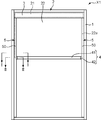
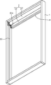
- FIG. 1 It is a schematic plan view which shows the screen apparatus which concerns on this embodiment. It is the II sectional view taken on the line shown in FIG. It is the II-II sectional view taken on the line shown in FIG. It is a schematic sectional drawing which shows progress in the manufacturing process of the screen apparatus which concerns on this embodiment, Comprising: The state which attached the outer side guide rail with respect to the frame member is shown. It is a schematic perspective view which shows progress in the manufacturing process of the screen apparatus which concerns on this embodiment, Comprising: The state which attached the outer side guide rail and the winding screen with respect to the frame member is shown.
- the screen device according to the present invention may include any constituent member that is not shown in each drawing referred to in this specification.
- the screen device X1 is a winding screen device applied to a window frame in a house or the like.
- the screen device X1 includes a frame member 1, a winding screen 2, a front cover 3, a weight bar 4, a pair of guide rails 5, and a plurality of fixing members 7.
- the screen device X1 may have a configuration in which a screen member 22 described later is wound up electrically, or may be configured in which the screen member 22 is manually wound up with a chain or the like.
- the screen device according to the present invention is also applied to systems other than the winding type.
- the screen device according to the present invention is applied not only to a window frame in a house, but also to a projector screen, for example.
- the frame member 1 is a member constituting the outer frame of the screen device X1.
- the frame member 1 has a rectangular shape in plan view.
- the rectangular area surrounded by the frame member 1 is an area opened and closed by a screen member 22 described later.
- the frame member 1 does not have to be rectangular in plan view, and can be appropriately changed according to the usage mode of the screen device X1. Further, the frame member 1 may not be provided. For example, a window frame in a house or the like may be used as the frame member 1.
- the winding screen 2 includes a winding shaft 21 and a screen member 22.
- the winding shaft 21 has a role of winding the screen member 22.
- the winding shaft 21 is a columnar member that extends in the short direction of the frame member 1.
- the winding shaft 21 is disposed along the upper frame of the frame member 1 in a region surrounded by the frame member 1.
- the winding shaft 21 is attached to both side frames of the frame member 1 so as to be rotatable in the circumferential direction of the winding shaft 21.
- the winding shaft 21 may be arranged along the lower frame of the frame member 1.
- the screen member 22 has a role of opening and closing a region surrounded by the frame member 1.
- the upper end portion of the screen member 22 is connected to the winding shaft 21.
- the screen member 22 is wound around the winding shaft 21 according to the rotation of the winding shaft 21, thereby opening a part or all of the region surrounded by the frame member 1. Further, the screen member 22 is sent out from the take-up shaft 21 according to the rotation of the take-up shaft 21, thereby closing part or all of the region surrounded by the frame member 1.
- the screen member 22 has side end portions 22a located at both ends of the screen member 22 in the left-right direction.
- Each side end 22a is a portion that is held by each inner guide rail 60 of each guide rail 5 described later.
- Each side end portion 22a is set to have a larger thickness than portions other than each side end portion 22a.
- Each side end 22a is formed, for example, by attaching a retaining member so as to cover the screen material from both the front and back surfaces with respect to both side ends in the left-right direction of the sheet-like screen material.
- each side edge part 22a may be formed by setting the thickness of the both-sides edge part itself in the left-right direction of a sheet-like screen raw material large compared with the thickness of parts other than the said both-sides edge part, for example. .
- the front cover 3 has a role of preventing the winding shaft 21 from being visually recognized by the user.
- the front cover 3 is arranged in front of the winding shaft 21, that is, on the user side so as to overlap the winding shaft 21 in plan view.
- the front cover 3 is fixed to the frame member 1 using, for example, a magnet sheet (not shown).
- the weight bar 4 has a role of applying an appropriate tension to the screen member 22 in the vertical direction of the screen member 22 in a state where the screen member 22 is fed from the winding shaft 21.
- the weight bar 4 has a main body 41 and a pair of left and right side caps 42.
- the main body 41 extends along the left-right direction of the screen member 22.
- the main body 41 is attached to the lower end of the screen member 22.
- the length of the main body 41 is set slightly shorter than the width of the screen member 22 in the left-right direction.
- Side caps 42 are attached to both ends of the lower end portion of the screen member 22 exposed from the main body portion 41 on both the left and right sides of the main body portion 41. Specifically, as shown in FIG.
- the side cap 42 includes one side member 42a and the other side member 42b.
- the one side member 42 a and the other side member 42 b are fixed by a fixing tool such as a screw (not shown) in a state where the lower end portion of the screen member 22 is sandwiched in the thickness direction of the screen member 22.
- the side cap 42 has a recess 42c between the one side member 42a and the other side member 42b.
- the end of the main body 41 is fitted in the recess 42c.
- the end of the side cap 42 opposite to the recess 42c is fitted in a recess 54 of the outer guide rail 50 described later.
- Each guide rail 5 has a role of guiding the vertical movement of the screen member 22.
- Each guide rail 5 is arranged along the both side frames of the frame member 1 in a region surrounded by the frame member 1.
- Each guide rail 5 includes an outer guide rail 50 and an inner guide rail 60.
- the outer guide rail 50 is a member corresponding to the rail housing member of the screen device according to the present invention.
- the outer guide rail 50 has a role of preventing the inner guide rail 60 from being visually recognized by the user by accommodating the inner guide rail 60.
- the outer guide rail 50 is a concave member extending along the vertical direction of the screen member 22.
- the outer guide rail 50 has a first side wall 51, a second side wall 52, a first bottom wall 53, a recess 54, a first intermediate wall 55, and a second intermediate wall 56.
- the first side wall 51 and the second side wall 52 extend along the left-right direction of the screen member 22 from both ends of the first bottom wall 53 in contact with the side frame of the frame member 1 in the thickness direction of the screen member 22.
- the first side wall 51 and the second side wall 52 face each other in the thickness direction of the screen member 22.
- a space surrounded by the first side wall 51, the second side wall 52, and the first bottom wall 53 is a recess 54.
- the first intermediate wall 55 and the second intermediate wall 56 extend from the first bottom wall 53 into the recess 54 along the left-right direction of the screen member 22.
- the first intermediate wall 55 and the second intermediate wall 56 face each other in the thickness direction of the screen member 22.
- the widths of the first intermediate wall 55 and the second intermediate wall 56 in the left-right direction of the screen member 22 are set to be smaller than the widths of the first side wall 51 and the second side wall 52 in the left-right direction of the screen member 22.
- the first intermediate wall 55 is located on the first side wall 51 side compared to the second intermediate wall 56
- the second intermediate wall 56 is on the second side wall 52 side compared to the first intermediate wall 55. Is located.
- the space between the first side wall 51 and the first intermediate wall 55 is referred to as a first space S1.
- a space between the second side wall 52 and the second intermediate wall 56 is referred to as a second space S2.
- a space between the first intermediate wall 55 and the second intermediate wall 56 is referred to as a third space S3.
- the outer guide rail 50 has a first side wall 51, a second side wall 52, a first bottom wall 53, a recess 54, a first intermediate wall 55, and a second intermediate wall 56.
- any concave member that can accommodate the inner guide rail 60 inside may be used.
- the fixing member 7 is a screwing member having a head portion 71 and a screw portion 72.
- the screw portion 72 extends from the concave portion 54 side to the side frame of the frame member 1 through the first bottom wall 53. Thereby, the screw portion 72 fixes the first bottom wall 53 and the side frame of the frame member 1.
- the head 71 of the fixing member 7 is disposed in the third space S3.
- the plurality of fixing members 7 are arranged at predetermined intervals along the vertical direction of the screen member 22.
- the plurality of fixing members 7 fix the outer guide rail 50 and the frame member 1.
- the number and arrangement of the fixing members 7 are arbitrary, and can be appropriately changed according to the usage mode of the screen device X1.
- the inner guide rail 60 is a member corresponding to the rail member of the screen device according to the present invention.
- the inner guide rail 60 serves to guide the vertical movement of the screen member 22. Similar to the outer guide rail 50, the inner guide rail 60 extends along the vertical direction of the screen member 22.
- the inner guide rail 60 includes a first rail member 61 and a second rail member 62.
- the first rail member 61 is a member that directly guides the vertical movement of the screen member 22.
- the first rail member 61 has a hollow shape.
- the first rail member 61 has a first accommodating portion 61a and a first slit 61b.
- the first accommodating portion 61 a corresponds to the hollow portion of the first rail member 61.
- the first accommodating portion 61 a extends along the vertical direction of the screen member 22.
- the first slit 61 b communicates the first housing portion 61 a and the outside of the first rail member 61.
- the first slit 61 b extends along the vertical direction of the screen member 22.
- the side end 22a of the screen member 22 is accommodated in the first accommodating portion 61a via the first slit 61b. In other words, the screen member 22 is located inside and outside the first housing portion 61a via the first slit 61b.
- the width of the first slit 61 b in the thickness direction of the screen member 22 is smaller than the thickness of the side end portion 22 a of the screen member 22. For this reason, the screen member 22 is restricted by the first rail member 61 from being displaced in the left-right direction. Further, the width of the first accommodating portion 61 a in the thickness direction of the screen member 22 is larger than the thickness of the side end portion 22 a of the screen member 22. For this reason, the screen member 22 is movable in the up-down direction of the screen member 22 in a state where the displacement of the screen member 22 in the left-right direction is restricted.
- the second rail member 62 is a member that holds the first rail member 61.
- the second rail member 62 includes a first opposing wall 62a, a second opposing wall 62b, a second bottom wall 62c, a second accommodating portion 62d, a second slit 62e, a first projecting portion 62f, a second projecting portion 62g, a plurality of It has a first tongue piece 62h, a plurality of second tongue pieces 62i, a first protrusion 62j, and a second protrusion 62k.
- the first opposing wall 62 a is a part facing the first side wall 51.
- the second opposing wall 62 b is a part that faces the second side wall 52.
- the second bottom wall 62 c is a part facing the first bottom wall 53.
- a space surrounded by the first opposing wall 62a, the second opposing wall 62b, and the second bottom wall 62c serves as a second accommodating portion 62d that accommodates the first rail member 61.
- a second slit 62e is provided on the upper wall of the second rail member 62 located on the opposite side of the second bottom wall 62c with the second housing portion 62d interposed therebetween.
- the second accommodating portion 62d communicates with the outside of the second rail member 62 through the second slit 62e.
- the 1st rail member 61 is accommodated in the 2nd accommodating part 62d. Thereby, the surface in which the 1st slit 61b was provided among the 1st rail members 61 is exposed from the 2nd accommodating part 62d in the 2nd slit 62e.
- An elastic body E ⁇ b> 1 is interposed between the inner peripheral surface of the second rail member 62 and the outer peripheral surface of the first rail member 61. Thereby, the space
- the first convex portion 62j extends from the first opposing wall 62a toward the first side wall 51 along the thickness direction of the screen member 22.
- the 2nd convex part 62k is extended in the 2nd side wall 52 side along the thickness direction of a screen member from the 2nd opposing wall 62b.
- the separation distance from the vertex of the first convex portion 62j to the vertex of the second convex portion 62k in the thickness direction of the screen member 22 is set to be substantially the same as the width of the concave portion 54 of the outer guide rail 50 in the thickness direction. ing.
- the second rail member 62 is accommodated in the concave portion 54 at a position where the first convex portion 62j contacts the first side wall 51 and the second convex portion 62k contacts the second side wall 52. This prevents the inner guide rail 60 from rattling in the recess 54.
- the first protrusion 62f extends from the end of the second bottom wall 62c on the first opposing wall 62a side to the first bottom wall 53 side along the left-right direction of the screen member 22.
- the first protrusion 62f is inserted into the first space S1.
- the second protrusion 62g extends from the end of the second bottom wall 62c on the second opposing wall 62b side to the first bottom wall 53 side along the left-right direction of the screen member 22.
- the second protrusion 62g is inserted into the second space S2.
- the inner guide rail 60 is completely accommodated in the recess 54 of the outer guide rail 50 at the insertion position where the first protrusion 62f is inserted into the first space S1 and the second protrusion 62g is inserted into the second space S2. Has been. Thereby, the inner guide rail 60 is in a state where it is not visually recognized by the user in the thickness direction of the screen member 22.
- the insertion position in the present embodiment is the contact position between the tip of the first projection 62f and the tip of the second projection 62g and the first bottom wall 53, or the tip of the first intermediate wall 55 and the second middle. The contact position of the front-end
- positioning and the number of the 1st projection parts 62f and the 2nd projection parts 62g are arbitrary, and can be suitably changed according to the usage condition of the screen apparatus X1.
- a single protrusion that extends from the center of the second bottom wall 62c in the thickness direction of the screen member 22 toward the first bottom wall 53 is provided. It is good also as a structure which inserts a projection part in 3rd space S3.
- the head 71 of the fixing member 7 may be disposed so as to avoid the protrusion in the third space S3, or may be disposed in the first space S1 or the second space S2.
- Each first tongue piece 62h extends from the first protrusion 62f along the protrusion direction of the first protrusion 62f, that is, the direction intersecting the left-right direction of the screen member 22. Specifically, some of the first tongue pieces 62h of the first tongue pieces 62h extend from the first protrusion 62f to the first side wall 51 side. The remaining first tongue piece 62h of the first tongue pieces 62h extends from the first protrusion 62f to the first intermediate wall 55 side. And each 1st tongue piece 62h is between the 1st projection part 62f and the 1st side wall 51, and between the 1st projection part 62f and the 1st intermediate wall 55 in the insertion position of the 1st projection part 62f.
- each first tongue piece 62 h is pressed against the first side wall 51 and the first intermediate wall 55.
- Each second tongue piece 62i extends from the second projecting portion 62g along the projecting direction of the second projecting portion 62g, that is, the direction intersecting the left-right direction of the screen member 22. Specifically, some second tongue pieces 62i out of the second tongue pieces 62i extend from the second protrusions 62g to the second side wall 52 side. The remaining second tongue piece 62i of the second tongue pieces 62i extends from the second protrusion 62g toward the second intermediate wall 56 side.
- each 2nd tongue piece 62i is between the 2nd projection part 62g and the 2nd side wall 52, and between the 2nd projection part 62g and the 2nd intermediate wall 56 in the said insertion position of the 2nd projection part 62g. It is elastically deformed. Accordingly, each second tongue piece 62 i is pressed against the second side wall 52 and the second intermediate wall 56.
- the first tongue pieces 62h and the second tongue pieces 62i are arranged in the outer guide rail 50 in the thickness direction of the screen member 22 at the insertion positions of the first protrusions 62f and the second protrusions 62g. It is in pressure contact with the peripheral surface. For this reason, the inner guide rail 60 is held by the outer guide rail 50 without any fixing work such as screwing. As a result, the inner guide rail 60 is in a state where it can be detached from the recess 54 of the outer guide rail 50 in the left-right direction of the screen member 22.
- first tongue pieces 62h of the first tongue pieces 62h extend from the first protrusions 62f toward the first side wall 51, and the remaining portions of the first tongue pieces 62h.
- the first tongue piece 62h extends from the first protrusion 62f toward the first intermediate wall 55, but is not limited thereto.
- each first tongue piece 62h may extend only from the first protrusion 62f toward the first side wall 51.
- a part of the second tongue pieces 62i of the second tongue pieces 62i extends from the second protrusion 62g toward the second side wall 52, and the remaining portion of the second tongue pieces 62i.
- each second tongue piece 62i may extend only from the second protrusion 62g to the second side wall 52 side.
- the inner guide rail 60 is constituted by two members, the first rail member 61 and the second rail member 62, but is not limited thereto.
- the inner guide rail 60 may be configured only by the second rail member 62, and the side end portion 22a of the screen member 22 may be accommodated directly in the second accommodation portion 62d.
- the thickness of the side end portion 22 a of the screen member 22 is set to be larger than the width of the second slit 62 e in the thickness direction of the screen member 22.
- the inner guide rail 60 may include a third rail member in addition to the first rail member 61 and the second rail member 62.
- the third rail member is accommodated in the first accommodating portion 61a and has a third accommodating portion and a third slit, and the side end portion of the screen member 22 is passed through the third slit to the third accommodating portion. 22a is accommodated.
- the thickness of the side end portion 22 a of the screen member 22 is set larger than the width of the third slit in the thickness direction of the screen member 22.
- the outer guide rail 50 holds the inner guide rail 60 so that the inner guide rail 60 can be attached to and detached from the recess 54 in the left-right direction of the screen member 22. For this reason, the maintainability of the screen member 22 is improved.
- the screen member is removed from the screen device as follows. It is necessary to desorb. First, the outer guide rail is removed from the side frame of the frame member.
- the engaging body between the screen member and the inner guide rail is detached from the outer guide rail.
- the inner guide rail 60 can be detached from the concave portion 54 of the outer guide rail 50 in the left-right direction of the screen member 22.
- the inner guide rail 60 can be removed from the concave portion 54 of the outer guide rail 50 without removing the outer guide rail 50 from the frame member 1.
- a troublesome process of removing the inner guide rail 60 from the concave portion 54 of the outer guide rail 50 along the vertical direction of the screen member 22 is unnecessary. Therefore, the engaging body of the screen member 22 and the inner guide rail 60 can be easily separated from the outer guide rail 50, thereby improving the maintainability of the screen member 22.
- the first tongue pieces 62h and the second tongue pieces 62i are elastically deformed in the first space S1 and the second space S2.
- the first tongue pieces 62 h and the second tongue pieces 62 i are pressed against the inner peripheral surface of the outer guide rail 50.
- the first protrusion 62f and the second protrusion 62g are held on the inner peripheral surface of the outer guide rail 50. For this reason, it can suppress that the 1st projection part 62f and the 2nd projection part 62g slip out carelessly from 1st space S1 and 2nd space S2, and can hold the inner side guide rail 60 on the outer side guide rail 50 appropriately. it can.
- the head 71 of the fixing member 7 is disposed in the third space S3.
- the third space S3 which is a dead space between the first intermediate wall 55 and the second intermediate wall 56 in the recess 54, is effectively utilized, and the outer guide rail 50 and the frame member 1 are fixed by the fixing member 7.
- the side frame can be fixed.
- the screen device X1 described above can be manufactured reasonably and easily, for example, by a method including the following steps.
- the construction method of the screen device X1 will be described in detail with reference to FIGS.
- a frame member 1 made of wood, metal material, resin material or the like is prepared.
- the frame member 1 is formed in a substantially rectangular shape in plan view.
- the winding screen 2 including the winding shaft 21 and the screen member 22 and the main body portion 41 of the weight bar 4 are prepared, and the winding in a state where the main body portion 41 is attached to the lower end portion of the screen member 22.
- a take screen 2 is attached to the frame member 1.
- the screen material such as cloth is formed in a substantially rectangular shape having an area comparable to the area surrounded by the frame member 1.
- the securing member which consists of resin materials etc. is attached to the both ends of the said screen raw material, ie, both long sides of a screen raw material.
- the tape-shaped retaining member is bent, and the retaining member is bonded to the both side ends so as to sandwich both side ends of the screen material from both sides of the screen material.
- the screen member 22 is formed.
- the upper end part of the screen member 22, ie, one short side of the screen member 22, is attached along the axial direction of the said winding shaft 21 with respect to the winding shaft 21 formed in the column shape.
- the screen member 22 can be wound around the winding shaft 21 in the circumferential direction of the winding shaft 21.
- the main body 41 is attached to the lower end of the screen member 22. Specifically, the main body 41 is attached along the short side of the screen member 22 that is located on the opposite side of the short side attached to the winding shaft 21.
- the length of the main body portion 41 is set smaller than the width of the lower end portion of the screen member 22, and both ends of the lower end portion from the main body portion 41 on both sides in the length direction of the main body portion 41 are set. Exposed.
- the winding screen 2 with the main body 41 attached in this way is arranged along the upper frame of the frame member 1 in the region surrounded by the frame member 1. And the winding shaft 21 in the winding screen 2 is fixed to the both side frames of the frame member 1 in a state in which the winding shaft 21 is rotatable in the circumferential direction of the winding shaft 21.
- an outer guide rail 50 made of a metal material or a resin material is prepared, and the outer guide rail 50 is attached to the frame member 1. Specifically, for example, by performing extrusion molding along one direction, the outer guide rail 50 having a concave shape extending along the one direction is formed.
- the outer guide rail 50 is fixed to the side frame of the frame member 1 via the fixing member 7.
- the screw portion 72 of the fixing member 7 extends from the recess 54 through the first bottom wall 53 to the side frame of the frame member 1, and the head 71 of the fixing member 7 is connected to the first intermediate wall 55 and the second intermediate wall. It arrange
- the inner guide rail 60 including the first rail member 61 and the second rail member 62 is prepared.
- a hollow first rail member 61 extending along one direction is formed by extruding a resin material.
- the hollow second rail member 62 extending in one direction is formed by extruding the resin material.
- the first tongue piece 62h and the second tongue piece 62i of the second rail member 62 have a lower elastic modulus than that of the portion other than the first tongue piece 62h and the second tongue piece 62i, for example, by coextrusion molding. Formed to be.
- the first rail member 61 is inserted into the second housing portion 62 d of the second rail member 62 along the length direction of the second rail member 62. Accordingly, the first rail member 61 is held in the second housing portion 62d with the first slit 61b exposed from the second slit 62e.
- the side end portion 22a of the screen member 22 is accommodated in the first accommodating portion 61a through the first slit 61b. Thereby, the displacement in the short side direction of the screen member 22, ie, the left-right direction of the screen member 22, is controlled.
- the inner guide rail 60 is accommodated in the recess 54 of the outer guide rail 50 along the left-right direction of the screen member 22.
- the first protrusion 62f is inserted into the first space S1 between the first side wall 51 and the first intermediate wall 55
- the second protrusion 62g is connected to the second side wall 52 and the second intermediate wall 56. Is inserted into the second space S2.
- the insertion is stopped at a position where the tip of the first intermediate wall 55 and the tip of the second intermediate wall 56 are in contact with the second bottom wall 62c.
- the inner guide rail 60 is completely accommodated in the concave portion 54 of the outer guide rail 50 at the insertion position where the insertion is stopped.
- first tongue piece 62 h and the second tongue piece 62 i are elastically deformed in the thickness direction of the screen member 22, a repulsive force due to the elastic deformation is applied to the inner peripheral surface of the outer guide rail 50. Thereby, the inner guide rail 60 is held by the outer guide rail 50.
- a front cover 3 made of a metal material or the like is prepared, and the front cover 3 is attached to the frame member 1.
- the front cover 3 is formed with a size that prevents the winding screen 2 from being visually recognized by the user in a state where the screen member 22 is completely wound around the winding shaft 21.
- the front cover 3 is disposed in front of the winding shaft 21 and is fixed to the frame member 1 via a magnet sheet (not shown).
- the side cap 42 of the weight bar 4 is prepared, and the side cap 42 is attached to the lower end of the screen member 22 exposed from the main body 41 on both sides in the length direction of the main body 41.
- a pair of one side member 42a and the other side member 42b constituting the side cap 42 are prepared.
- the one-side member 42a and the other-side member 42b are arranged so as to face each other across the portion exposed from the main body portion 41 in the lower end portion of the screen member 22.
- the end of the main body 41 is disposed in the recess 42c, which is a space between the one side member 42a and the other side member 42b, and a part of the side cap 42 is disposed in the recess 54 of the outer guide rail 50.
- the one side member 42a and the other side member 42b are fixed by screws or the like. Thereby, the vertical movement of the weight bar 4 is guided by the outer guide rail 50.
- the main body 41 may be attached to the lower end portion of the screen member 22 together with the side cap 42 in this step.
- the inner guide rail 60 can be held by the outer guide rail 50 without separately providing a fixture, and therefore the inner guide rail 60 is moved in the left-right direction of the screen member 22. It can be made removable from the recessed part 54 of this. Thereby, the maintainability of the screen apparatus X1 can be improved.
- the side cap 42 is attached to a portion of the lower end portion of the screen member 22 exposed from the main body portion 41. For this reason, when removing the inner guide rail 60 from the recess 54 of the outer guide rail 50 in the left-right direction of the screen member 22, first, the side cap 42 is removed by separating the one side member 42a and the other side member 42b.
- the inner guide rail 60 can be easily removed from the recess 54 without any problem.
- the procedure for removing the inner guide rail 60 from the recess 54 of the outer guide rail 50 is not limited to the above procedure.
- the inner guide rail 60 may be removed from the concave portion 54 after the main body 41 is also removed from the screen member 22 in addition to the side cap 42, or the main body 41 and the side cap 42 are attached to the screen member 22.
- the inner guide rail 60 may be removed from the recess 54.
- the screen apparatus X1 can be manufactured by a simple process.
- the screen device X1 according to the present embodiment can be variously modified as follows.
- the first tongue pieces 62h and the second tongue pieces are associated with the insertion of the first protrusions 62f and the second protrusions 62g into the first space S1 and the second space S2.
- the inner guide rail 60 is held by the outer guide rail 50 due to the elastic deformation of 62i, but is not limited thereto.
- the inner guide rail 60 may be held by the outer guide rail 50 by any method within a range not departing from the gist of the present invention.
- the first tongue pieces 62h and the second tongue pieces 62i do not exist, and the first protrusions 62f and the second protrusions into the first space S1 and the second space S2.
- a configuration in which the inner guide rail 60 is held by the outer guide rail 50 only by inserting the portion 62g may be employed.
- each first tongue piece 62h is first from the first opposing wall 62a.
- a configuration may be employed in which each second tongue piece 62i extends from the second opposing wall 62b to the second side wall 52 side while extending to the side wall 51 side.
- a repulsive force of the elastic deformation is applied to the first side wall 51 by elastically deforming each first tongue piece 62h between the first side wall 51 and the first opposing wall 62a.
- the second side wall 52 is subjected to elastic repulsion force by elastically deforming each second tongue piece 62i between the second side wall 52 and the second opposing wall 62b.
- the inner guide rail 60 is held by the outer guide rail 50.
- the first protrusion 62f and the second protrusion 62g extending along the left-right direction of the screen member 22 do not exist.
- variety of the outer side guide rail 50 and the inner side guide rail 60 in the left-right direction of the screen member 22 can be made small compared with the screen apparatus X1 which concerns on this embodiment.
- the screen device extends along the vertical direction of the screen member and the screen member so that the screen member can move in the vertical direction while restricting the displacement of the screen member in the horizontal direction.
- the rail housing member holds the rail member so that the rail member can be detached from the recess in the left-right direction of the screen member. Can be easily removed from the recess of the rail housing member. For this reason, for example, in a state where the rail housing member is attached to a frame member for fixing the rail housing member along the window frame or the like, the rail member can be removed from the recess of the rail housing member. A troublesome process of drawing the member from the recess of the rail housing member along the vertical direction of the screen member becomes unnecessary. Therefore, the engaging body of the screen member and the rail member can be easily separated from the rail housing member, and the maintainability of the screen member is improved.
- the rail member extends along the up-and-down direction of the screen member and accommodates the side end portion of the screen member, and extends along the up-and-down direction and communicates the inside and outside of the containing portion.
- the width of the slit is smaller than the thickness of the side end portion of the screen member, and the rail member is accommodated in the accommodating portion by the side end portion of the screen member through the slit. By doing so, it is preferable to restrict the displacement of the screen member in the left-right direction.
- the width of the slit to be smaller than the thickness of the side end portion of the screen member, the side end portion can be prevented from slipping out of the rail member through the slit. For this reason, the displacement in the left-right direction of a screen member is controlled, and it can suppress that a screen member and a rail member isolate
- the rail housing member includes a first side wall and a second side wall located on both sides in the thickness direction of the screen member across the concave portion, a first bottom wall connecting the first side wall and the second side wall, A first intermediate wall extending from the first bottom wall to the recess, and a second intermediate wall extending from the first bottom wall to the recess and positioned closer to the second side wall than the first intermediate wall.
- the rail member includes a second bottom wall facing the first bottom wall, a first protrusion extending from the second bottom wall toward the first bottom wall, and the first protrusion from the first protrusion.
- a second tongue piece extending in a direction intersecting with the second protrusion from the portion, and the first protrusion Is inserted into the space between the first side wall and the first intermediate wall, so that the first tongue piece is located between the first protrusion and the first side wall in the thickness direction of the screen member or
- the first protrusion and the first intermediate wall are elastically deformed, and the second protrusion is inserted into the space between the second side wall and the second intermediate wall.
- Two tongue pieces are elastically deformed between the second projecting portion and the second side wall or between the second projecting portion and the second intermediate wall in the thickness direction, whereby the rail housing member is moved to the rail. It is preferable to hold the member.
- the first protrusion is inserted into the space between the first side wall and the first intermediate wall.
- the second protrusion is inserted into the space between the second side wall and the second intermediate wall. Accordingly, the first tongue piece and the second tongue piece are elastically deformed in the thickness direction of the screen member, and the repulsive force of the elastic deformation is at least of the first side wall, the first intermediate wall, the second side wall, and the second intermediate wall. Join one.
- the first tongue and the second tongue cause the first protrusion and the second protrusion to be a space between the first side wall and the first intermediate wall and a space between the second side wall and the second intermediate wall. Can be prevented from inadvertently exiting. Therefore, the rail member can be appropriately held by the rail housing member.
- the rail housing member has a first side wall and a second side wall located on both sides in the thickness direction of the screen member with the recess interposed therebetween, and the rail member has a first facing facing the first side wall.
- the rail housing member may hold the rail member.
- the rail member extends from the first opposing wall of the rail member toward the first side wall of the rail housing member, and the second side wall of the rail housing member extends from the second opposing wall of the rail member.
- a second tongue extending to the side.
Landscapes
- Engineering & Computer Science (AREA)
- Structural Engineering (AREA)
- Architecture (AREA)
- Civil Engineering (AREA)
- Physics & Mathematics (AREA)
- General Physics & Mathematics (AREA)
- Operating, Guiding And Securing Of Roll- Type Closing Members (AREA)
- Overhead Projectors And Projection Screens (AREA)
Abstract
スクリーン装置X1は、スクリーン部材22と、スクリーン部材22の上下方向に沿って延びるとともに、スクリーン部材22の左右方向における変位を規制しつつスクリーン部材22が上下方向に移動可能となるようにスクリーン部材22の側端部22aを保持する内側ガイドレール60と、スクリーン部材22の上下方向に沿って延びるとともに、内側ガイドレール60を収容する凹部54を有する外側ガイドレール50と、を備え、外側ガイドレール50は、スクリーン部材22の左右方向において内側ガイドレール60を凹部54から着脱可能な状態で保持する。
Description
本発明は、スクリーン装置に関する。
従来、スクリーン装置としては、例えば特許文献1に記載された巻取式スクリーン装置が知られている。この巻取式スクリーン装置は、スクリーン部材に相当するネットと、当該スクリーン部材が巻付けられた巻取軸と、スクリーン部材の左右方向における側端部に取り付けられた係止部材と、当該係止部材を収容する中空状の抜止部材と、当該抜止部材を収容する中空状の支持部材と、を備えている。抜止部材は、レール部材として機能する部材であって、その内部に係止部材を収容することにより、スクリーン部材の左右方向における変位を規制するとともに当該スクリーン部材の上下方向における変位を許容する。支持部材は、レール収容部材として機能する部材であって、スクリーン部材の左右方向において抜止部材が支持部材から脱離しないように当該抜止部材を収容している。
特許文献1に記載の巻取式スクリーン装置では、スクリーン部材の左右方向において、レール部材によってスクリーン部材の変位が規制されるとともに、レール収容部材によって当該レール収容部材に対するレール部材の脱離が規制される。このため、例えばスクリーン部材のメンテナンスを行う場合には、以下のようにして巻取式スクリーン装置からスクリーン部材を脱離させる必要がある。まず、レール収容部材を窓枠等に沿って固定するための枠部材から、当該レール収容部材を取り外す。そして、スクリーン部材の上下方向に沿ってレール収容部材からレール部材および係止部材を抜き取ることにより、巻取式スクリーン装置からレール部材を脱離させる。
このように、巻取式スクリーン装置からスクリーン部材を脱離させる場合、煩雑な工程が必要となる。
本発明の目的は、上述の問題を解決したスクリーン装置を提供することである。
本発明の一局面に従うスクリーン装置は、スクリーン部材と、前記スクリーン部材の上下方向に沿って延びるとともに、前記スクリーン部材の左右方向における変位を規制しつつ前記スクリーン部材が前記上下方向に移動可能となるように前記スクリーン部材の側端部を保持するレール部材と、前記上下方向に沿って延びるとともに、前記レール部材を収容する凹部を有するレール収容部材と、を備え、前記レール収容部材は、前記左右方向において前記レール部材を前記凹部から着脱可能な状態で保持することを特徴とする。
以下、本発明の一実施形態について、図面を参照しながら説明する。但し、以下で参照する各図は、説明の便宜上、本発明の一実施形態の構成部材のうち、本発明を説明するために必要な主要部材を簡略化して示したものである。したがって、本発明に係るスクリーン装置は、本明細書が参照する各図に示されていない任意の構成部材を備え得る。
図1~図3に示すように、スクリーン装置X1は、住宅等における窓枠に適用される巻取式のスクリーン装置である。スクリーン装置X1は、枠部材1、巻取スクリーン2、前面カバー3、ウェイトバー4、一対のガイドレール5、および複数の固定部材7を備えている。スクリーン装置X1は、例えば、後述するスクリーン部材22を電動で巻き取る構成であってもよいし、当該スクリーン部材22をチェーン等によって手動で巻き取る構成であってもよい。なお、本発明に係るスクリーン装置は、巻取式以外の方式にも適用される。また、本発明に係るスクリーン装置は、住宅等における窓枠のみならず、例えば、プロジェクタスクリーン等にも適用される。
枠部材1は、スクリーン装置X1の外枠を構成する部材である。本実施形態では、枠部材1は、平面視して矩形状である。ここで、当該枠部材1によって取り囲まれる矩形状の領域は、後述するスクリーン部材22によって開閉される領域となる。なお、枠部材1は、平面視して矩形状でなくともよく、スクリーン装置X1の使用態様に応じて適宜変更することができる。また、枠部材1はなくともよく、例えば、住宅等における窓枠を枠部材1として利用してもよい。
巻取スクリーン2は、巻取軸21およびスクリーン部材22を備えている。
巻取軸21は、スクリーン部材22を巻き取る役割を有する。巻取軸21は、枠部材1の短手方向に延びる円柱形状の部材である。巻取軸21は、枠部材1によって取り囲まれる領域において、当該枠部材1の上枠に沿って配置されている。また、巻取軸21は、当該巻取軸21の周方向に回動可能な状態で、枠部材1の両側枠に取り付けられている。なお、巻取軸21は、枠部材1の下枠に沿って配置されていてもよい。
スクリーン部材22は、枠部材1によって取り囲まれる領域を開閉する役割を有する。スクリーン部材22の上端部は、巻取軸21に接続されている。スクリーン部材22は、巻取軸21の回動に応じて当該巻取軸21に巻き取られることにより、枠部材1によって取り囲まれる領域の一部または全部を開放する。また、スクリーン部材22は、巻取軸21の回動に応じて当該巻取軸21から送り出されることにより、枠部材1によって取り囲まれる領域の一部または全部を閉鎖する。
スクリーン部材22は、当該スクリーン部材22の左右方向の両端に位置する側端部22aを有している。各側端部22aは、後述する各ガイドレール5の各内側ガイドレール60にそれぞれ保持される部位である。各側端部22aは、当該各側端部22a以外の部位に比して厚みが大きく設定されている。各側端部22aは、例えば、シート状のスクリーン素材の左右方向における両側端に対して当該スクリーン素材を表裏両面から覆うように抜止部材が取り付けられることにより形成される。なお、各側端部22aは、例えば、シート状のスクリーン素材の左右方向における両側端部自体の厚みを当該両側端部以外の部位の厚みに比して大きく設定することにより形成されてもよい。
前面カバー3は、巻取軸21が使用者から視認されることを抑止する役割を有する。前面カバー3は、平面視して巻取軸21と重なるように、当該巻取軸21の前方、すなわち使用者側に配置されている。前面カバー3は、例えば、図示しないマグネットシート等を用いて枠部材1に固定されている。
ウェイトバー4は、巻取軸21からスクリーン部材22が送り出された状態において、スクリーン部材22に対して当該スクリーン部材22の上下方向に適度な張力を与える役割を有する。ウェイトバー4は、本体部41と左右一対のサイドキャップ42とを有している。本体部41は、スクリーン部材22の左右方向に沿って延びている。本体部41は、スクリーン部材22の下端部に取り付けられている。本体部41の長さは、スクリーン部材22の左右方向における幅よりも少し短く設定されている。そして、本体部41の左右両側において当該本体部41から露出したスクリーン部材22の下端部の両端にサイドキャップ42が取り付けられている。具体的には、図3に示すように、サイドキャップ42は、一方側部材42aと他方側部材42bを含んでいる。そして、一方側部材42aと他方側部材42bとは、スクリーン部材22の厚み方向において当該スクリーン部材22の下端部を挟み込んだ状態で図示しないビス等の固定具によって固定されている。サイドキャップ42は、一方側部材42aと他方側部材42bとの間において凹部42cを有している。凹部42cには、本体部41の端部が嵌め込まれている。また、サイドキャップ42のうち凹部42cとは反対側の端部は、後述する外側ガイドレール50の凹部54に嵌め込まれている。
各ガイドレール5は、スクリーン部材22の上下動をガイドする役割を有する。各ガイドレール5は、枠部材1によって取り囲まれる領域において当該枠部材1の両側枠に沿ってそれぞれ配置されている。各ガイドレール5は、外側ガイドレール50および内側ガイドレール60を備えている。
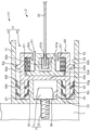
外側ガイドレール50は、本発明に係るスクリーン装置のレール収容部材に相当する部材である。外側ガイドレール50は、内側ガイドレール60を収容することにより当該内側ガイドレール60が使用者から視認されることを抑止する役割を有する。外側ガイドレール50は、スクリーン部材22の上下方向に沿って延びる凹型の部材である。外側ガイドレール50は、第1側壁51、第2側壁52、第1底壁53、凹部54、第1中間壁55、および第2中間壁56を有している。
第1側壁51と第2側壁52とは、枠部材1の側枠に接する第1底壁53のうちスクリーン部材22の厚み方向における両端から、スクリーン部材22の左右方向に沿って延びている。第1側壁51と第2側壁52とは、スクリーン部材22の厚み方向において互いに対向している。これらの第1側壁51、第2側壁52、および第1底壁53によって取り囲まれる空間が凹部54となる。また、第1中間壁55と第2中間壁56とは、第1底壁53からスクリーン部材22の左右方向に沿って凹部54内へそれぞれ伸びている。第1中間壁55と第2中間壁56とは、スクリーン部材22の厚み方向において互いに対向している。スクリーン部材22の左右方向における第1中間壁55および第2中間壁56の幅は、スクリーン部材22の左右方向における第1側壁51および第2側壁52の幅よりも小さく設定されている。また、第1中間壁55は、第2中間壁56に比して第1側壁51側に位置しており、第2中間壁56は、第1中間壁55に比して第2側壁52側に位置している。本実施形態では、第1側壁51と第1中間壁55との間の空間を第1空間S1と称する。また、第2側壁52と第2中間壁56との間の空間を第2空間S2と称する。また、第1中間壁55と第2中間壁56との間の空間を第3空間S3と称する。
なお、本実施形態では、外側ガイドレール50は、第1側壁51、第2側壁52、第1底壁53、凹部54、第1中間壁55、および第2中間壁56を有しているが、これに限らず、内側ガイドレール60を内部に収容可能な凹状の部材であればよい。
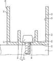
ここで、外側ガイドレール50は、複数の固定部材7を介して枠部材1に固定されている。固定部材7は、頭部71およびネジ部72を有するネジ止め部材である。ネジ部72は、凹部54側から第1底壁53を貫通して枠部材1の側枠に延びている。これにより、ネジ部72は、第1底壁53と枠部材1の側枠とを固定している。そして、ネジ部72が外側ガイドレール50と枠部材1とを固定した状態において、固定部材7の頭部71は、第3空間S3に配置されている。本実施形態では、図示は省略するが、複数の固定部材7がスクリーン部材22の上下方向に沿って所定の間隔を空けて配置されている。そして、複数の固定部材7は、外側ガイドレール50と枠部材1とを固定している。なお、固定部材7の個数および配置は任意であって、スクリーン装置X1の使用態様に応じて適宜変更することができる。
内側ガイドレール60は、本発明に係るスクリーン装置のレール部材に相当する部材である。内側ガイドレール60は、スクリーン部材22における上下動をガイドする役割を有する。内側ガイドレール60は、外側ガイドレール50と同様に、スクリーン部材22の上下方向に沿って延びている。内側ガイドレール60は、第1レール部材61および第2レール部材62を備えている。
第1レール部材61は、スクリーン部材22における上下動を直接ガイドする部材である。第1レール部材61は、中空形状をなしている。第1レール部材61は、第1収容部61aと、第1スリット61bと、を有している。第1収容部61aは、第1レール部材61の中空部分に対応している。第1収容部61aは、スクリーン部材22の上下方向に沿って延びている。第1スリット61bは、第1収容部61aと第1レール部材61の外部とを連通している。第1スリット61bは、スクリーン部材22の上下方向に沿って延びている。スクリーン部材22の側端部22aは、第1スリット61bを介して第1収容部61aに収容されている。換言すれば、スクリーン部材22は、第1スリット61bを介して第1収容部61aの内部および外部に位置している。
ここで、スクリーン部材22の厚み方向における第1スリット61bの幅は、スクリーン部材22の側端部22aの厚みよりも小さい。このため、スクリーン部材22は、第1レール部材61によって当該スクリーン部材22の左右方向における変位を規制されている。また、スクリーン部材22の厚み方向における第1収容部61aの幅は、スクリーン部材22の側端部22aの厚みよりも大きい。このため、スクリーン部材22は、当該スクリーン部材22の左右方向における変位が規制された状態で、当該スクリーン部材22の上下方向において移動可能である。
第2レール部材62は、第1レール部材61を保持する部材である。第2レール部材62は、第1対向壁62a、第2対向壁62b、第2底壁62c、第2収容部62d、第2スリット62e、第1突起部62f、第2突起部62g、複数の第1舌片62h、複数の第2舌片62i、第1凸部62j、および第2凸部62kを有している。
第1対向壁62aは、第1側壁51に対向する部位である。第2対向壁62bは、第2側壁52に対向する部位である。第2底壁62cは、第1底壁53に対向する部位である。これらの第1対向壁62a、第2対向壁62b、および第2底壁62cによって取り囲まれる空間は、第1レール部材61を収容する第2収容部62dとなる。また、第2レール部材62のうち当該第2収容部62dを挟んで第2底壁62cの反対側に位置する上壁には、第2スリット62eが設けられている。第2収容部62dは、第2スリット62eを通じて、第2レール部材62の外部に連通している。ここで、第1レール部材61は、第2収容部62dに収容されている。これにより、第1レール部材61のうち第1スリット61bが設けられた面は、第2スリット62eにおいて第2収容部62dから露出している。そして、第2レール部材62の内周面と第1レール部材61の外周面との間には、弾性体E1が介在している。これにより、枠部材1の両側枠に沿ってそれぞれ配置された各第1レール部材61同士の間隔が調整される。当該間隔は、スクリーン部材22に対して当該スクリーン部材22の左右方向に適度な張力を与えることができる間隔に設定される。
第1凸部62jは、第1対向壁62aからスクリーン部材22の厚み方向に沿って第1側壁51側に延びている。第2凸部62kは、第2対向壁62bからスクリーン部材の厚み方向に沿って第2側壁52側に延びている。ここで、スクリーン部材22の厚み方向における第1凸部62jの頂点から第2凸部62kの頂点までの離間距離は、当該厚み方向における外側ガイドレール50の凹部54の幅と略同一に設定されている。このため、第2レール部材62は、第1凸部62jが第1側壁51に接するとともに第2凸部62kが第2側壁52に接する位置において、凹部54内に収容されている。これにより、凹部54内において内側ガイドレール60にガタツキが発生することが抑止される。
第1突起部62fは、第2底壁62cのうち第1対向壁62a側の端部からスクリーン部材22の左右方向に沿って第1底壁53側に延びている。第1突起部62fは、第1空間S1に挿入されている。第2突起部62gは、第2底壁62cのうち第2対向壁62b側の端部からスクリーン部材22の左右方向に沿って第1底壁53側に延びている。第2突起部62gは、第2空間S2に挿入されている。内側ガイドレール60は、第1突起部62fが第1空間S1に挿入されるとともに第2突起部62gが第2空間S2に挿入された挿入位置において、外側ガイドレール50の凹部54に完全に収容されている。これにより、内側ガイドレール60は、スクリーン部材22の厚み方向において使用者から視認されない状態にある。なお、本実施形態における前記挿入位置とは、第1突起部62fの先端および第2突起部62gの先端と第1底壁53との接触位置、あるいは第1中間壁55の先端および第2中間壁56の先端と第2底壁62cとの接触位置を指す。
なお、第1突起部62fおよび第2突起部62gの配置および個数は任意であって、スクリーン装置X1の使用態様に応じて適宜変更することができる。例えば、第1突起部62fおよび第2突起部62gに代えて、スクリーン部材22の厚み方向における第2底壁62cの中央部から第1底壁53側に延びる単一の突起部を設け、当該突起部を第3空間S3に挿入する構成としてもよい。この場合、固定部材7の頭部71は、第3空間S3において前記突起部を避けるように配置されてもよいし、第1空間S1または第2空間S2に配置されてもよい。
各第1舌片62hは、第1突起部62fの突起方向、すなわちスクリーン部材22の左右方向に交差する方向に沿って、当該第1突起部62fから延びている。具体的には、各第1舌片62hのうち一部の第1舌片62hは、第1突起部62fから第1側壁51側に延びている。また、各第1舌片62hのうち残部の第1舌片62hは、第1突起部62fから第1中間壁55側に延びている。そして、各第1舌片62hは、第1突起部62fの前記挿入位置において、第1突起部62fと第1側壁51との間および第1突起部62fと第1中間壁55との間で弾性変形している。これにより、各第1舌片62hは、第1側壁51および第1中間壁55に圧接されている。各第2舌片62iは、第2突起部62gの突起方向、すなわちスクリーン部材22の左右方向に交差する方向に沿って、当該第2突起部62gから延びている。具体的には、各第2舌片62iのうち一部の第2舌片62iは、第2突起部62gから第2側壁52側に延びている。また、各第2舌片62iのうち残部の第2舌片62iは、第2突起部62gから第2中間壁56側に延びている。そして、各第2舌片62iは、第2突起部62gの前記挿入位置において、第2突起部62gと第2側壁52との間および第2突起部62gと第2中間壁56との間で弾性変形している。これにより、各第2舌片62iは、第2側壁52および第2中間壁56に圧接されている。
このように、各第1舌片62hおよび各第2舌片62iは、第1突起部62fおよび第2突起部62gの前記挿入位置にて、スクリーン部材22の厚み方向において外側ガイドレール50の内周面に圧接されている。このため、内側ガイドレール60は、例えばネジ止め等の固定作業を伴うことなく外側ガイドレール50に保持されることになる。これにより、内側ガイドレール60は、スクリーン部材22の左右方向において外側ガイドレール50の凹部54から脱着可能な状態にある。
なお、スクリーン装置X1では、各第1舌片62hのうち一部の第1舌片62hが第1突起部62fから第1側壁51側に延びており、各第1舌片62hのうち残部の第1舌片62hが第1突起部62fから第1中間壁55側に延びているが、これに限らない。例えば、各第1舌片62hは、第1突起部62fから第1側壁51側にのみ延びていてもよい。また、スクリーン装置X1では、各第2舌片62iのうち一部の第2舌片62iが第2突起部62gから第2側壁52側に延びており、各第2舌片62iのうち残部の第2舌片62iが第2突起部62gから第2中間壁56側に延びているが、これに限らない。例えば、各第2舌片62iは、第2突起部62gから第2側壁52側にのみ延びていてもよい。
また、スクリーン装置X1では、内側ガイドレール60は、第1レール部材61と第2レール部材62との2つの部材によって構成されているが、これに限らない。例えば、内側ガイドレール60は、第2レール部材62のみによって構成され、第2収容部62dに直接スクリーン部材22の側端部22aが収容されてもよい。この場合、スクリーン部材22の側端部22aの厚みは、当該スクリーン部材22の厚み方向における第2スリット62eの幅よりも大きく設定される。また、例えば、内側ガイドレール60は、第1レール部材61および第2レール部材62に加えて、第3レール部材を有してもよい。具体的には、第3レール部材は、第1収容部61aに収容されるとともに第3収容部および第3スリットを有し、当該第3スリットを通じて第3収容部にスクリーン部材22の側端部22aが収容される。この場合、スクリーン部材22の側端部22aの厚みは、当該スクリーン部材22の厚み方向における第3スリットの幅よりも大きく設定される。
このように、スクリーン装置X1では、スクリーン部材22の左右方向において内側ガイドレール60が凹部54から着脱可能となるように、外側ガイドレール50が内側ガイドレール60を保持している。このため、スクリーン部材22のメンテナンス性が向上する。例えば、内側ガイドレールがスクリーン部材の左右方向において凹部から脱離不可能なように外側ガイドレールに固定されているスクリーン装置では、スクリーン部材をメンテナンスするに際して、以下のようにスクリーン装置からスクリーン部材を脱離させる必要がある。まず、外側ガイドレールを枠部材の側枠から取り外す。そして、スクリーン部材の上下方向に沿って外側ガイドレールの凹部から内側ガイドレールを抜き取ることにより、スクリーン部材と内側ガイドレールとの係合体を外側ガイドレールから脱離させる。これに対して本実施形態に係るスクリーン装置X1では、スクリーン部材22の左右方向において内側ガイドレール60を外側ガイドレール50の凹部54から脱着可能である。このため、外側ガイドレール50を枠部材1から取り外すことなく内側ガイドレール60を外側ガイドレール50の凹部54から取り外すことができる。しかも、内側ガイドレール60をスクリーン部材22の上下方向に沿って外側ガイドレール50の凹部54から抜き取るような煩わしい工程が不要である。そのため、スクリーン部材22と内側ガイドレール60との係合体を外側ガイドレール50から容易に分離することができ、これによりスクリーン部材22のメンテナンス性が向上する。
さらに、スクリーン装置X1では、第1空間S1および第2空間S2において各第1舌片62hおよび各第2舌片62iが弾性変形する。そして、スクリーン部材22の厚み方向において、各第1舌片62hおよび各第2舌片62iが外側ガイドレール50の内周面に圧接される。これにより、第1突起部62fおよび第2突起部62gが外側ガイドレール50の内周面に保持される。このため、第1空間S1および第2空間S2から第1突起部62fおよび第2突起部62gが不用意に抜け出ることを抑止でき、内側ガイドレール60を外側ガイドレール50に適正に保持させることができる。
さらに、スクリーン装置X1では、第3空間S3に固定部材7の頭部71が配置されている。このため、凹部54内における第1中間壁55と第2中間壁56との間のデッドスペースである第3空間S3を有効に活用して、固定部材7によって外側ガイドレール50と枠部材1の側枠とを固定することができる。
以上説明したスクリーン装置X1は、例えば以下の工程を含む方法により、合理的かつ容易に製造されることが可能である。以下では、図4~図8を参照しつつ、スクリーン装置X1の施工方法について詳述する。
1)巻取スクリーン2、本体部41、および外側ガイドレール50の取付け工程
まず、図4および図5を参照しつつ、巻取スクリーン2、本体部41、および外側ガイドレール50の取付け工程について説明する。
まず、図4および図5を参照しつつ、巻取スクリーン2、本体部41、および外側ガイドレール50の取付け工程について説明する。
この工程では、まず、木材、金属材料、あるいは樹脂材料等からなる枠部材1が準備される。当該枠部材1は、平面視して略矩形状に形成される。
次に、巻取軸21およびスクリーン部材22を備えた巻取スクリーン2と、ウェイトバー4の本体部41と、が準備され、スクリーン部材22の下端部に本体部41が取り付けられた状態における巻取スクリーン2が枠部材1に取り付けられる。
具体的には、布製等のスクリーン素材が、枠部材1が取り囲む領域と同程度の面積を有する略矩形状に形成される。そして、前記スクリーン素材の両側端、すなわちスクリーン素材の両長辺に対して、樹脂材料等からなる抜止部材が取り付けられる。より具体的には、テープ状の抜止部材が折り曲げられ、当該抜止部材がスクリーン素材の両側端を当該スクリーン素材の両面から挟み込むようにして当該両側端に接着される。このようにして、スクリーン部材22が形成される。そして、スクリーン部材22の上端部、すなわちスクリーン部材22の一方の短辺は、円柱形状に形成された巻取軸21に対して当該巻取軸21の軸方向に沿って取り付けられる。これにより、スクリーン部材22は、巻取軸21に対して当該巻取軸21の周方向に巻き取り可能な状態となる。
次に、本体部41がスクリーン部材22の下端部に取り付けられる。具体的には、本体部41は、スクリーン部材22のうち巻取軸21に取り付けられた短辺の反対側に位置する短辺に沿って取り付けられる。ここで、本体部41の長さは、スクリーン部材22の下端部の幅に比して小さく設定されており、本体部41の長さ方向における両側において当該本体部41から前記下端部の両端が露出する。
このようにして本体部41が取り付けられた状態における巻取スクリーン2は、枠部材1によって取り囲まれる領域において、枠部材1の上枠に沿って配置される。そして、巻取スクリーン2における巻取軸21は、当該巻取軸21の周方向に回動可能な状態で、枠部材1の両側枠に固定される。
次に、金属材料あるいは樹脂材料等からなる外側ガイドレール50が準備され、当該外側ガイドレール50が枠部材1に取り付けられる。具体的には、例えば一方方向に沿って押出し成形を行うことにより、当該一方方向に沿って延びる凹形状をなす外側ガイドレール50が成形される。そして、外側ガイドレール50は、固定部材7を介して枠部材1の側枠に固定される。この際、固定部材7のネジ部72が凹部54から第1底壁53を貫通して枠部材1の側枠に延び、当該固定部材7の頭部71が第1中間壁55と第2中間壁56との間の空間である第3空間S3に配置される。
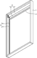
2)内側ガイドレール60の嵌め込み工程
次に、図6および図7を参照しつつ、内側ガイドレール60の嵌め込み工程について説明する。
次に、図6および図7を参照しつつ、内側ガイドレール60の嵌め込み工程について説明する。
この工程では、まず、第1レール部材61および第2レール部材62を備える内側ガイドレール60が準備される。
具体的には、まず、樹脂材料を押出成形することによって、一方方向に沿って延びる中空形状の第1レール部材61が成形される。
次に、樹脂材料を押出成形することによって、一方方向に沿って延びる中空形状の第2レール部材62が成形される。なお、第2レール部材62の第1舌片62hおよび第2舌片62iは、例えば共押出成形によって、当該第1舌片62hおよび第2舌片62i以外の部位に比して弾性率が低くなるように形成される。
次に、第2レール部材62の長さ方向に沿って当該第2レール部材62の第2収容部62dに第1レール部材61が挿入される。これにより、第1レール部材61は、第1スリット61bが第2スリット62eから露出した状態で第2収容部62dに保持される。
次に、第1レール部材61の長さ方向に沿って、第1スリット61bを通じてスクリーン部材22の側端部22aが第1収容部61aに収容される。これにより、スクリーン部材22の短辺方向、すなわちスクリーン部材22の左右方向における変位が規制される。
そして、内側ガイドレール60がスクリーン部材22の左右方向に沿って外側ガイドレール50の凹部54に収容される。このとき、第1突起部62fが第1側壁51と第1中間壁55との間の第1空間S1に挿入されるとともに、第2突起部62gが第2側壁52と第2中間壁56との間の第2空間S2に挿入される。前記の挿入は、第1中間壁55の先端および第2中間壁56の先端と第2底壁62cとが接触する位置において停止される。このようにして前記の挿入が停止された挿入位置において、内側ガイドレール60が外側ガイドレール50の凹部54に完全に収容される。また、スクリーン部材22の厚み方向において第1舌片62hおよび第2舌片62iが弾性変形することにより、当該弾性変形による反発力が外側ガイドレール50の内周面に加わる。これにより、内側ガイドレール60が外側ガイドレール50に保持される。
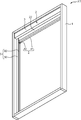
3)前面カバー3およびサイドキャップ42の取付け工程
次に、図8を参照しつつ、前面カバー3およびウェイトバー4のサイドキャップ42の取付け工程について説明する。
次に、図8を参照しつつ、前面カバー3およびウェイトバー4のサイドキャップ42の取付け工程について説明する。
この工程では、まず、金属材料等からなる前面カバー3が準備され、当該前面カバー3が枠部材1に取り付けられる。具体的には、前面カバー3は、スクリーン部材22が巻取軸21に完全に巻き取られた状態における巻取スクリーン2が使用者から視認されるのを防ぐ程度の大きさで形成される。そして、前面カバー3は、巻取軸21の前方に配置されるとともに、図示しないマグネットシート等を介して枠部材1に固定される。
次に、ウェイトバー4のサイドキャップ42が準備され、当該サイドキャップ42が本体部41の長さ方向の両側において当該本体部41から露出したスクリーン部材22の下端部に取り付けられる。具体的には、まず、サイドキャップ42を構成する一対の一方側部材42aおよび他方側部材42bが準備される。そして、一方側部材42aと他方側部材42bとがスクリーン部材22の下端部のうち本体部41から露出した部位を挟んで対向するように配置される。このとき、一方側部材42aと他方側部材42bとの間の空間である凹部42cに本体部41の端部が配置されるとともに、外側ガイドレール50の凹部54にサイドキャップ42の一部が配置される。そして、この状態において一方側部材42aと他方側部材42bとがビス等によって固定される。これにより、ウェイトバー4の上下動が外側ガイドレール50によってガイドされることになる。なお、前述の本体部41は、この工程においてサイドキャップ42とともにスクリーン部材22の下端部に取り付けられてもよい。
以上のスクリーン装置X1の施工方法では、固定器具を別途設けることなく外側ガイドレール50に内側ガイドレール60を保持させることができるため、スクリーン部材22の左右方向において内側ガイドレール60を外側ガイドレール50の凹部54から脱着可能とすることができる。これにより、スクリーン装置X1のメンテナンス性を向上することができる。
特に、上記のスクリーン装置X1の施工方法では、巻取スクリーン2を枠部材1に取り付ける段階において、ウェイトバー4のうち本体部41のみをスクリーン部材22の下端部に取り付けている。また、内側ガイドレール60を外側ガイドレール50の凹部54に収容した後の段階において、サイドキャップ42をスクリーン部材22の下端部のうち本体部41から露出した部位に取り付けている。このため、スクリーン部材22の左右方向において内側ガイドレール60を外側ガイドレール50の凹部54から取り外す際には、まず一方側部材42aと他方側部材42bとを分離することによりサイドキャップ42を取り外す。これにより、スクリーン部材22の左右方向において本体部41と外側ガイドレール50との間に所定の隙間を生じさせることができ、当該隙間を有効に活用して、スクリーン部材22から本体部41を取り外すことなく内側ガイドレール60を凹部54から容易に取り外すことができる。なお、内側ガイドレール60を外側ガイドレール50の凹部54から取り外す手順は、上記の手順に限らない。例えば、サイドキャップ42に加えて本体部41もスクリーン部材22から取り外した後に内側ガイドレール60を凹部54から取り外してもよいし、本体部41およびサイドキャップ42がスクリーン部材22に取り付けられた状態で内側ガイドレール60を凹部54から取り外してもよい。
さらに、上記のスクリーン装置X1の施工方法では、内側ガイドレール60が外側ガイドレール50の凹部54に嵌め込まれる際に、当該凹部54に対して内側ガイドレール60が収容されると同時に、第1空間S1および第2空間S2に対して第1突起部62fおよび第2突起部62gが挿入され、これにより各第1舌片62hおよび各第2舌片62iが弾性変形することで内側ガイドレール60が外側ガイドレール50に保持される。このため、簡易な工程でスクリーン装置X1を製造することができる。
なお、今回開示された実施形態は、全ての点で例示であって、制限的なものではないと考えられるべきである。本発明の範囲は、上記した実施形態の説明ではなく請求の範囲によって示され、さらに請求の範囲と均等な意味および範囲内での全ての変更が含まれる。
例えば、本実施形態に係るスクリーン装置X1は、以下のとおり、様々な変更が可能である。
本実施形態に係るスクリーン装置X1では、第1空間S1および第2空間S2への第1突起部62fおよび第2突起部62gの挿入に伴って、各第1舌片62hおよび各第2舌片62iが弾性変形することにより、内側ガイドレール60が外側ガイドレール50に保持されているが、これに限らない。本発明の趣旨を逸脱しない範囲においては、内側ガイドレール60が外側ガイドレール50に如何なる手法で保持されていてもよい。
例えば、本実施形態に係るスクリーン装置X1において、各第1舌片62hおよび各第2舌片62iが存在せず、第1空間S1および第2空間S2への第1突起部62fおよび第2突起部62gの挿入のみによって内側ガイドレール60が外側ガイドレール50に保持される構成を採用してもよい。
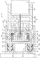
また、図9に示すように、本実施形態に係るスクリーン装置X1において、第1突起部62fおよび第2突起部62gが存在せず、各第1舌片62hが第1対向壁62aから第1側壁51側に延びるとともに、各第2舌片62iが第2対向壁62bから第2側壁52側に延びる構成を採用してもよい。このような場合、第1側壁51には、各第1舌片62hが第1側壁51と第1対向壁62aとの間で弾性変形することにより当該弾性変形の反発力が加わる。また、第2側壁52には、各第2舌片62iが第2側壁52と第2対向壁62bとの間で弾性変形することにより当該弾性変形の反発力が加わる。これにより、内側ガイドレール60は、外側ガイドレール50に保持される。
このように、図9に示すスクリーン装置X1の変形例では、スクリーン部材22の左右方向に沿って延びる第1突起部62fおよび第2突起部62gが存在しない。このため、本実施形態に係るスクリーン装置X1に比してスクリーン部材22の左右方向における外側ガイドレール50および内側ガイドレール60の幅を小さくすることができる。
ここで、上記の実施形態について概説する。
本実施形態に係るスクリーン装置は、スクリーン部材と、前記スクリーン部材の上下方向に沿って延びるとともに、前記スクリーン部材の左右方向における変位を規制しつつ前記スクリーン部材が前記上下方向に移動可能となるように前記スクリーン部材の側端部を保持するレール部材と、前記上下方向に沿って延びるとともに、前記レール部材を収容する凹部を有するレール収容部材と、を備え、前記レール収容部材は、前記左右方向において前記レール部材を前記凹部から着脱可能な状態で保持する。
上記のスクリーン装置では、スクリーン部材の左右方向においてレール部材が凹部から着脱可能となるように、レール収容部材がレール部材を保持するため、スクリーン部材のメンテナンスを行う場合に、スクリーン部材の側端部が保持されるレール部材をレール収容部材の凹部から容易に取り外すことができる。このため、例えばレール収容部材を窓枠等に沿って固定するための枠部材に当該レール収容部材が取り付けられた状態で、レール部材をレール収容部材の凹部から取り外すことができ、これにより当該レール部材をスクリーン部材の上下方向に沿ってレール収容部材の凹部から抜き取るような煩わしい工程が不要となる。そのため、スクリーン部材とレール部材との係合体をレール収容部材から容易に分離することができ、スクリーン部材のメンテナンス性が向上する。
前記レール部材は、前記スクリーン部材の前記上下方向に沿って延びるとともに前記スクリーン部材の前記側端部を収容する収容部と、前記上下方向に沿って延びるとともに前記収容部の内部と外部とを連通するスリットと、を有し、前記スリットの幅は、前記スクリーン部材の前記側端部の厚みよりも小さく、前記レール部材は、前記スクリーン部材の前記側端部が前記スリットを通じて前記収容部に収容されることにより、前記スクリーン部材の前記左右方向における変位を規制することが好ましい。
上記のスクリーン装置では、スリットの幅をスクリーン部材の側端部の厚みよりも小さく設定することにより、当該側端部がスリットを通じてレール部材の外部へ抜け出ることを抑止できる。このため、スクリーン部材の左右方向における変位が規制され、当該左右方向においてスクリーン部材とレール部材とが分離することを抑止できる。
前記レール収容部材は、前記凹部を挟んで前記スクリーン部材の厚み方向の両側に位置する第1側壁および第2側壁と、前記第1側壁および前記第2側壁を連結する第1底壁と、前記第1底壁から前記凹部へ延びる第1中間壁と、前記第1底壁から前記凹部へ延びるとともに前記第1中間壁よりも前記第2側壁側に位置する第2中間壁と、を有し、前記レール部材は、前記第1底壁に対向する第2底壁と、前記第2底壁から前記第1底壁側へ延びる第1突起部と、前記第1突起部から当該第1突起部の突起方向と交差する方向に延びる第1舌片と、前記第2底壁から前記第1底壁側へ延びるとともに前記第1突起部とは離間する第2突起部と、前記第2突起部から当該第2突起部と交差する方向に延びる第2舌片と、を有し、前記第1突起部が前記第1側壁と前記第1中間壁との間の空間に挿入されることにより、前記第1舌片が前記スクリーン部材の厚み方向において前記第1突起部と前記第1側壁との間または前記第1突起部と前記第1中間壁との間で弾性変形するとともに、前記第2突起部が前記第2側壁と前記第2中間壁との間の空間に挿入されることにより、前記第2舌片が前記厚み方向において前記第2突起部と前記第2側壁との間または前記第2突起部と前記第2中間壁との間で弾性変形し、これにより前記レール収容部材が前記レール部材を保持することが好ましい。
上記のスクリーン装置では、スクリーン部材の左右方向に沿ってレール収容部材の凹部にレール部材を収容するに際して、第1突起部が第1側壁と第1中間壁との間の空間に挿入されるとともに、第2突起部が第2側壁と第2中間壁との間の空間に挿入される。これにより、第1舌片および第2舌片がスクリーン部材の厚み方向において弾性変形し、当該弾性変形の反発力が少なくとも第1側壁、第1中間壁、第2側壁、および第2中間壁のいずれかに加わる。このため、第1舌片および第2舌片によって第1突起部および第2突起部が第1側壁と第1中間壁との間の空間および第2側壁と第2中間壁との間の空間から不用意に抜け出ることを抑止できる。そのため、レール部材をレール収容部材に適正に保持させることができる。
また、前記レール収容部材は、前記凹部を挟んで前記スクリーン部材の厚み方向の両側に位置する第1側壁および第2側壁を有し、前記レール部材は、前記第1側壁に対向する第1対向壁と、前記第1対向壁から前記第1側壁側に延びる第1舌片と、前記第2側壁に対向する第2対向壁と、前記第2対向壁から前記第2側壁側に延びる第2舌片と、を有し、前記第1舌片が前記第1側壁と前記第1対向壁との間において弾性変形するとともに、前記第2舌片が前記第2側壁と前記第2対向壁との間において弾性変形し、これにより前記レール収容部材が前記レール部材を保持してもよい。
上記のスクリーン装置では、レール部材が当該レール部材の第1対向壁からレール収容部材の第1側壁側に延びる第1舌片と、当該レール部材の第2対向壁からレール収容部材の第2側壁側に延びる第2舌片と、を有する。このため、スクリーン部材の左右方向に沿ってレール部材をレール収容部材の凹部に収容する際に、当該収容過程において第1舌片および第2舌片をスクリーン部材の厚み方向に弾性変形させることができる。これにより、凹部へのレール部材の収容とレール収容部材におけるレール部材の保持とを同時に達成することができる。
Claims (4)
- スクリーン部材と、
前記スクリーン部材の上下方向に沿って延びるとともに、前記スクリーン部材の左右方向における変位を規制しつつ前記スクリーン部材が前記上下方向に移動可能となるように前記スクリーン部材の側端部を保持するレール部材と、
前記上下方向に沿って延びるとともに、前記レール部材を収容する凹部を有するレール収容部材と、を備え、
前記レール収容部材は、前記左右方向において前記レール部材を前記凹部から着脱可能な状態で保持する、スクリーン装置。 - 前記レール部材は、前記上下方向に沿って延びるとともに前記スクリーン部材の前記側端部を収容する収容部と、前記上下方向に沿って延びるとともに前記収容部の内部と外部とを連通するスリットと、を有し、
前記スリットの幅は、前記スクリーン部材の前記側端部の厚みよりも小さく、
前記レール部材は、前記スクリーン部材の前記側端部が前記スリットを通じて前記収容部に収容されることにより、前記スクリーン部材の前記左右方向における変位を規制する、請求項1に記載のスクリーン装置。 - 前記レール収容部材は、前記凹部を挟んで前記スクリーン部材の厚み方向の両側に位置する第1側壁および第2側壁と、前記第1側壁および前記第2側壁を連結する第1底壁と、前記第1底壁から前記凹部へ延びる第1中間壁と、前記第1底壁から前記凹部へ延びるとともに前記第1中間壁よりも前記第2側壁側に位置する第2中間壁と、を有し、
前記レール部材は、前記第1底壁に対向する第2底壁と、前記第2底壁から前記第1底壁側へ延びる第1突起部と、前記第1突起部から当該第1突起部の突起方向と交差する方向に延びる第1舌片と、前記第2底壁から前記第1底壁側へ延びるとともに前記第1突起部とは離間する第2突起部と、前記第2突起部から当該第2突起部と交差する方向に延びる第2舌片と、を有し、
前記第1突起部が前記第1側壁と前記第1中間壁との間の空間に挿入されることにより前記第1舌片が前記スクリーン部材の厚み方向において前記第1突起部と前記第1側壁との間または前記第1突起部と前記第1中間壁との間で弾性変形するとともに、前記第2突起部が前記第2側壁と前記第2中間壁との間の空間に挿入されることにより前記第2舌片が前記厚み方向において前記第2突起部と前記第2側壁との間または前記第2突起部と前記第2中間壁との間で弾性変形し、これにより前記レール収容部材が前記レール部材を保持する、請求項2に記載のスクリーン装置。 - 前記レール収容部材は、前記凹部を挟んで前記スクリーン部材の厚み方向の両側に位置する第1側壁および第2側壁を有し、
前記レール部材は、前記第1側壁に対向する第1対向壁と、前記第1対向壁から前記第1側壁側に延びる第1舌片と、前記第2側壁に対向する第2対向壁と、前記第2対向壁から前記第2側壁側に延びる第2舌片と、を有し、
前記第1舌片が前記第1側壁と前記第1対向壁との間において弾性変形するとともに、前記第2舌片が前記第2側壁と前記第2対向壁との間において弾性変形し、これにより前記レール収容部材が前記レール部材を保持する、請求項2に記載のスクリーン装置。
Priority Applications (2)
| Application Number | Priority Date | Filing Date | Title |
|---|---|---|---|
| US15/307,280 US9982483B2 (en) | 2014-04-30 | 2015-04-03 | Screen device |
| EP15786375.4A EP3130742B1 (en) | 2014-04-30 | 2015-04-03 | Screen device |
Applications Claiming Priority (2)
| Application Number | Priority Date | Filing Date | Title |
|---|---|---|---|
| JP2014093573A JP6228506B2 (ja) | 2014-04-30 | 2014-04-30 | スクリーン装置 |
| JP2014-093573 | 2014-04-30 |
Publications (1)
| Publication Number | Publication Date |
|---|---|
| WO2015166765A1 true WO2015166765A1 (ja) | 2015-11-05 |
Family
ID=54358502
Family Applications (1)
| Application Number | Title | Priority Date | Filing Date |
|---|---|---|---|
| PCT/JP2015/060592 Ceased WO2015166765A1 (ja) | 2014-04-30 | 2015-04-03 | スクリーン装置 |
Country Status (4)
| Country | Link |
|---|---|
| US (1) | US9982483B2 (ja) |
| EP (1) | EP3130742B1 (ja) |
| JP (1) | JP6228506B2 (ja) |
| WO (1) | WO2015166765A1 (ja) |
Families Citing this family (17)
| Publication number | Priority date | Publication date | Assignee | Title |
|---|---|---|---|---|
| CA2979212A1 (en) * | 2015-03-09 | 2016-09-15 | Ventana 3D, Llc | Foil tensioning system for pepper's ghost illusion |
| EP3098376A1 (en) * | 2015-05-29 | 2016-11-30 | Plastex SA | Upright for a shading system, removable flange of the upright and corresponding coupling means |
| KR102527214B1 (ko) * | 2016-05-04 | 2023-04-28 | 삼성디스플레이 주식회사 | 롤러블 표시 장치 |
| US10538962B2 (en) * | 2016-06-16 | 2020-01-21 | Hall Labs Llc | Easy installation headrail assembly |
| US9719292B1 (en) * | 2016-08-03 | 2017-08-01 | Defender Screens International LLC | Self-tensioning magnetic tracks and track assemblies |
| US11421474B2 (en) * | 2016-08-03 | 2022-08-23 | Defender Screens International, Llc | Self-tensioning magnetic tracks and track assemblies |
| US10260280B2 (en) | 2017-01-03 | 2019-04-16 | Mechoshade Systems, Llc | Systems and methods for roller blind channel coupling |
| US10253563B2 (en) | 2017-01-03 | 2019-04-09 | Mechoshade Systems, Llc | Base channel coupling |
| US10662705B2 (en) * | 2017-04-14 | 2020-05-26 | Hall Labs Llc | Track system for retractable wall |
| US20190048658A1 (en) * | 2017-08-09 | 2019-02-14 | Professional Blinds System Inc. | Construction assembly for installing a roller blind or the like |
| US11326395B2 (en) * | 2019-04-03 | 2022-05-10 | Michael Heissenberg | Retractable screen with horizontal tensioning track and vertical biasing member |
| US11840883B2 (en) * | 2019-09-13 | 2023-12-12 | Inpro Corporation | Shade system with breakable end tips |
| KR102782043B1 (ko) * | 2019-10-25 | 2025-03-13 | 엘지전자 주식회사 | 디스플레이 디바이스 |
| US12211402B2 (en) * | 2019-12-27 | 2025-01-28 | Lg Electronics Inc. | Display device having sagging prevention structure |
| US12180786B2 (en) | 2020-02-24 | 2024-12-31 | Defender Screens International LLC | Retractable screen systems |
| DE202020103347U1 (de) * | 2020-06-10 | 2020-06-18 | Alukon Kg | Führungseinsatz für eine Führungsschiene eines Behangsystems; Führungsschiene für ein Behangsystem und Behangsystem zum Führen eines Behangs |
| US20230349231A1 (en) * | 2022-05-02 | 2023-11-02 | Defender Screens International, Llc | Retractable screen systems |
Citations (3)
| Publication number | Priority date | Publication date | Assignee | Title |
|---|---|---|---|---|
| JPH11141250A (ja) * | 1997-09-04 | 1999-05-25 | Morito Co Ltd | ロールスクリーン装置 |
| JP2004211298A (ja) * | 2002-12-26 | 2004-07-29 | Tachikawa Blind Mfg Co Ltd | ロールブラインドのスクリーン案内装置 |
| JP2012172505A (ja) * | 2011-02-24 | 2012-09-10 | Seiki Hanbai Co Ltd | 建物開口部用スクリーン装置 |
Family Cites Families (13)
| Publication number | Priority date | Publication date | Assignee | Title |
|---|---|---|---|---|
| US3220469A (en) * | 1963-08-28 | 1965-11-30 | Robert G Oehmig | Screen frame |
| US4233790A (en) * | 1979-01-08 | 1980-11-18 | Donel Corporation | Extrusions and building structures |
| JPH0629440Y2 (ja) | 1986-02-07 | 1994-08-10 | セイキ販売株式会社 | 巻取式スクリーン装置 |
| US7699091B2 (en) * | 2003-08-11 | 2010-04-20 | Steel Stitch Corporation | Awning system with snap-on functional components |
| JP3881665B2 (ja) * | 2004-03-24 | 2007-02-14 | 東海興業株式会社 | パッキン及びその装着方法 |
| EP1953018B1 (de) * | 2007-01-31 | 2010-03-17 | ArvinMeritor GmbH | Führungssystem für ein Rollo eines Schiebedachsystems |
| ITPS20070039A1 (it) * | 2007-12-07 | 2009-06-08 | Garattoni Dario Di R I | Sistema per l'installazione verticale o orizzontale di rete/tessuto/crystal con zip saldata o cucita |
| AU2010100720B4 (en) * | 2009-10-29 | 2011-09-08 | Acmeda Pty Ltd | A blind system |
| SE534653C2 (sv) * | 2010-10-15 | 2011-11-08 | Erco Systems Ab | Styrskena för rullgardin |
| TW201241297A (en) * | 2011-04-06 | 2012-10-16 | Komatsu Denki Sangyo Kabushiki Kaisha | Sheet shutter |
| JP5849450B2 (ja) * | 2011-06-15 | 2016-01-27 | アイシン精機株式会社 | サンシェード装置 |
| GB2502039B (en) * | 2012-02-29 | 2017-11-15 | Ideas By Design Ltd | Apparatus for mounting a screen guide rail |
| JP6228504B2 (ja) | 2014-04-11 | 2017-11-08 | フクビ化学工業株式会社 | スクリーン装置およびその製造方法 |
-
2014
- 2014-04-30 JP JP2014093573A patent/JP6228506B2/ja active Active
-
2015
- 2015-04-03 WO PCT/JP2015/060592 patent/WO2015166765A1/ja not_active Ceased
- 2015-04-03 US US15/307,280 patent/US9982483B2/en active Active
- 2015-04-03 EP EP15786375.4A patent/EP3130742B1/en active Active
Patent Citations (3)
| Publication number | Priority date | Publication date | Assignee | Title |
|---|---|---|---|---|
| JPH11141250A (ja) * | 1997-09-04 | 1999-05-25 | Morito Co Ltd | ロールスクリーン装置 |
| JP2004211298A (ja) * | 2002-12-26 | 2004-07-29 | Tachikawa Blind Mfg Co Ltd | ロールブラインドのスクリーン案内装置 |
| JP2012172505A (ja) * | 2011-02-24 | 2012-09-10 | Seiki Hanbai Co Ltd | 建物開口部用スクリーン装置 |
Non-Patent Citations (1)
| Title |
|---|
| See also references of EP3130742A4 * |
Also Published As
| Publication number | Publication date |
|---|---|
| EP3130742A1 (en) | 2017-02-15 |
| US9982483B2 (en) | 2018-05-29 |
| JP6228506B2 (ja) | 2017-11-08 |
| EP3130742B1 (en) | 2022-09-28 |
| US20170044826A1 (en) | 2017-02-16 |
| EP3130742A4 (en) | 2018-02-28 |
| JP2015209731A (ja) | 2015-11-24 |
Similar Documents
| Publication | Publication Date | Title |
|---|---|---|
| JP6228506B2 (ja) | スクリーン装置 | |
| JP6228504B2 (ja) | スクリーン装置およびその製造方法 | |
| JP2017038034A (ja) | スライドレールキット及びそのブラケットデバイス | |
| US9682577B2 (en) | Paper storage, printer and method for using multiple types of mediums | |
| WO2013009460A4 (en) | Hand tool and method for cutting plastic fiber optic cable without error | |
| JP2009043728A (ja) | バックライトユニットを有する表示装置 | |
| KR101356315B1 (ko) | 서랍 정리용 칸막이 | |
| JP3925933B2 (ja) | 光コネクタの分解治具 | |
| CN108474401B (zh) | 穿壁安装装置 | |
| KR101226087B1 (ko) | 창문이탈방지구 | |
| JP6574348B2 (ja) | スクリーン装置 | |
| US9309079B1 (en) | Bottom taping tape roll replacement | |
| EP3409873B1 (en) | Tension cord mounting for an architectural covering | |
| JP5056994B2 (ja) | 組付状態解除阻止機構 | |
| JP2016020600A (ja) | スクリーン装置 | |
| JP6469600B2 (ja) | スクリーン装置 | |
| KR102051893B1 (ko) | 블라인드 고정용 브라켓 및 그를 포함하는 블라인드 장치 | |
| JP4761891B2 (ja) | 内視鏡の湾曲操作装置 | |
| JP6242144B2 (ja) | シート収納装置及び画像形成装置 | |
| JP6647087B2 (ja) | 引戸装置 | |
| KR101001908B1 (ko) | 개선된 문의 안전장치 | |
| JP6570318B2 (ja) | 基板ユニットのロック構造 | |
| US7543624B2 (en) | Curtain hook apparatus and method | |
| KR101434304B1 (ko) | 롤 스크린용 손잡이 조립체 | |
| KR101852401B1 (ko) | 모헤어 삽입장치 |
Legal Events
| Date | Code | Title | Description |
|---|---|---|---|
| WWE | Wipo information: entry into national phase |
Ref document number: 15307280 Country of ref document: US |
|
| NENP | Non-entry into the national phase |
Ref country code: DE |
|
| 121 | Ep: the epo has been informed by wipo that ep was designated in this application |
Ref document number: 15786375 Country of ref document: EP Kind code of ref document: A1 |
|
| REEP | Request for entry into the european phase |
Ref document number: 2015786375 Country of ref document: EP |
|
| WWE | Wipo information: entry into national phase |
Ref document number: 2015786375 Country of ref document: EP |