WO2015169065A1 - 一种简易锁扣装置 - Google Patents
一种简易锁扣装置 Download PDFInfo
- Publication number
- WO2015169065A1 WO2015169065A1 PCT/CN2014/089558 CN2014089558W WO2015169065A1 WO 2015169065 A1 WO2015169065 A1 WO 2015169065A1 CN 2014089558 W CN2014089558 W CN 2014089558W WO 2015169065 A1 WO2015169065 A1 WO 2015169065A1
- Authority
- WO
- WIPO (PCT)
- Prior art keywords
- connecting member
- locking
- piece
- locking device
- tongue
- Prior art date
- Legal status (The legal status is an assumption and is not a legal conclusion. Google has not performed a legal analysis and makes no representation as to the accuracy of the status listed.)
- Ceased
Links
Images


Classifications
-
- F—MECHANICAL ENGINEERING; LIGHTING; HEATING; WEAPONS; BLASTING
- F16—ENGINEERING ELEMENTS AND UNITS; GENERAL MEASURES FOR PRODUCING AND MAINTAINING EFFECTIVE FUNCTIONING OF MACHINES OR INSTALLATIONS; THERMAL INSULATION IN GENERAL
- F16B—DEVICES FOR FASTENING OR SECURING CONSTRUCTIONAL ELEMENTS OR MACHINE PARTS TOGETHER, e.g. NAILS, BOLTS, CIRCLIPS, CLAMPS, CLIPS OR WEDGES; JOINTS OR JOINTING
- F16B1/00—Devices for securing together, or preventing relative movement between, constructional elements or machine parts
- F16B1/02—Means for securing elements of mechanisms after operation
- F16B1/04—Means for securing elements of mechanisms after operation disengaged by movement of the actuating member of the element
-
- E—FIXED CONSTRUCTIONS
- E05—LOCKS; KEYS; WINDOW OR DOOR FITTINGS; SAFES
- E05C—BOLTS OR FASTENING DEVICES FOR WINGS, SPECIALLY FOR DOORS OR WINDOWS
- E05C1/00—Fastening devices with bolts moving rectilinearly
- E05C1/002—Fastening devices with bolts moving rectilinearly perpendicular to the surface on which the fastener is mounted
-
- E—FIXED CONSTRUCTIONS
- E05—LOCKS; KEYS; WINDOW OR DOOR FITTINGS; SAFES
- E05C—BOLTS OR FASTENING DEVICES FOR WINGS, SPECIALLY FOR DOORS OR WINDOWS
- E05C1/00—Fastening devices with bolts moving rectilinearly
- E05C1/004—Fastening devices with bolts moving rectilinearly parallel to the surface on which the fastener is mounted
-
- E—FIXED CONSTRUCTIONS
- E05—LOCKS; KEYS; WINDOW OR DOOR FITTINGS; SAFES
- E05C—BOLTS OR FASTENING DEVICES FOR WINGS, SPECIALLY FOR DOORS OR WINDOWS
- E05C9/00—Arrangements of simultaneously actuated bolts or other securing devices at well-separated positions on the same wing
- E05C9/002—Arrangements of simultaneously actuated bolts or other securing devices at well-separated positions on the same wing with arrangements allowing the wing to be slam-shut, e.g. by securing elements with latching action
Definitions
- the invention relates to the field of mechanical equipment, and in particular to a simple locking device.
- a plurality of single-performance locking components (such as a handle buckle, a rotary lock or a movable pin lock) are generally used for locking the movable device.
- such a locking device generally only realizes a mechanical opening and closing of a single action, and realizes a function through a plurality of mechanisms and/or a plurality of actions, and cannot perform a plurality of state actions by a single mechanism to realize
- the locking function in different states makes the operation quite cumbersome.
- the embodiment of the invention provides a simple locking device, which can realize the action of a single mechanism to perform a plurality of states to lock the movable device, thereby making the operation simpler and more convenient, and is beneficial to improving the use experience.
- a latch bracket a latch tab, a tension spring, a tensile sidewall, a base, at least two guide shafts, a connecting member 7a and a connecting member 7b;
- the latch bracket includes: a locking piece, at least two guiding holes and a snapping piece;
- the tensile sidewall is fixed on the base
- At least two of the guide shafts respectively mount the lock bracket on the base through at least two of the guide holes, and the lock bracket cooperates with the guide hole to move;
- the latching tongue is movably connected to the locking piece, the locking tongue is provided with a front end protrusion, and the locking piece is provided with an oblique protrusion;
- the connecting member 7a is provided with a slot position that cooperates with the oblique portion of the locking piece, and a convex portion that is convexly engaged with the front end of the locking tongue;
- the connecting member 7b is provided with a card hole that engages with the engaging piece.
- the latching tongue further comprises: a spring hook
- the spring hook is disposed on a side of the latching tongue and is fixedly connected to the tension spring;
- the latch bracket further includes: a handle position
- the handle position is disposed on the latch bracket adjacent to an end of the engaging piece for providing a force point when the latch bracket is toggled.
- the connecting member 7a and the connecting member 7b are mounted on the same movable device;
- the connecting member 7a and the connecting member 7b are disposed on the same movable device.
- the connecting member 7a and the connecting member 7b are respectively at symmetrical positions of the movable device.
- the simple locking device further includes: a pin shaft;
- the pin shaft is configured to movably connect the latching tongue to the locking piece.
- the guiding directions of the guiding holes are all the same.
- the guide shaft is a bolt
- the guide shaft is a convex shaft disposed on the base.
- the tensile sidewall is welded to the base
- the tensile sidewall is secured to the base by bolts.
- a simple locking device includes: a latch bracket, a latching tongue, a tension spring, a tensile sidewall, a base, at least two guiding shafts, a connecting member 7a and a connecting member 7b;
- the latch bracket includes: a locking piece, at least two guiding holes and a engaging piece; the stretching sidewall is fixed on the base; at least two of the guiding shafts respectively pass through at least two of the guiding a hole is mounted on the base, the lock bracket is movable with the guide hole; one end of the tension spring is fixed on the stretch sidewall, and the other end is connected to the lock
- the latching tongue is fixedly connected; the latching tongue is movably connected to the locking piece, the latching tongue is provided with a front end protrusion, and the locking piece is provided with an oblique convex part, the connecting part 7a is arranged a slot portion that cooperates with the oblique portion of the locking piece, and a protrusion portion that is convex
- the latch bracket, the latching tongue, the tension spring, the stretching sidewall, the base, the at least two guiding shafts, the connecting member 7a and the connecting member 7b constitute a locking mechanism, which can realize a single
- the mechanism makes a plurality of states of action, no longer a mechanical opening and closing of a single action, and locks the movable device connected to the connecting member 7a and the connecting member 7b in different states, thereby making the operation simpler. Convenient and conducive to improving the experience.
- FIG. 1 is a schematic structural view of an embodiment of a simple locking device according to an embodiment of the present invention
- FIG. 2 is a schematic structural view of a lock bracket according to an embodiment of the present invention, wherein FIG. 2a is a lock buckle a top view of the frame, Figure 2b is a front view of the buckle bracket;
- FIG. 3 is a schematic structural view of a movable device locked to the simple locking device according to an embodiment of the present invention, wherein FIG. 3a is a top view of the simple locking device, and FIG. 3b is a right side view of the simple locking device; 3c is a front view of the simple locking device, and FIG. 3d is a left side view of the simple locking device;
- FIG. 4 is a schematic structural view of a latching tongue according to an embodiment of the present invention, wherein FIG. 4a is a front view of the latching tongue, FIG. 4b is a side view of the latching tongue, and FIG. 4c is a top view of the latching tongue;
- FIG. 5 is a schematic structural view of a susceptor according to an embodiment of the present invention, wherein FIG. 5a is a plan view of the susceptor 5, and FIG. 5b is a front view of the susceptor 5;
- Figure 6 is a schematic structural view of a connecting member 7a according to an embodiment of the present invention.
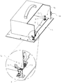
- FIG. 7 is a structural diagram and a partial enlarged view of the movable device locked on the simple locking device according to an embodiment of the present invention.
- FIG. 8 is a schematic structural diagram of an operation of a simple locking device in an initial state, a locked state, and an unlocked state according to an embodiment of the present invention, wherein FIG. 8a shows the simple locking device in an initial state, and FIG. 8b shows a simple locking device. The device is in a locked state, and Figure 8c shows the simple locking device in an unlocked state.
- the embodiment of the invention provides a simple locking device for realizing a single mechanism to perform a plurality of states of actions to lock the movable device, thereby making the operation simpler and more convenient, and is beneficial to improving the use experience.
- an embodiment of a simple locking device includes:
- the latch bracket 1, the latching tongue 2, the tension spring 3, the stretched side wall 4, the base 5, the at least two guide shafts 6, the connecting member 7a and the connecting member 7b are as shown in FIG.
- FIG. 2a is a top view of the lock bracket 1 and FIG. 2b is a lock bracket 1 Front view.
- the latch bracket 1 includes a locking piece 11, at least two guiding holes 12 and a engaging piece 13; the guiding directions of the guiding holes 12 are all the same.
- the locking piece 11 can be a rigid piece perpendicular to the plane of the guiding hole 12, and the front end of the locking piece 11 is inclined.
- the convex portion 111 can be engaged with the slot position 71 of the connecting member 7a to realize the locking function, and the specific operation will be described below. As can be seen from FIG.
- the locking piece 11 is disposed at the left end of the latch bracket 1
- the engaging piece 13 is disposed at the right end of the latch bracket 1
- the engaging piece 13 can engage the card hole on the connecting member 7b. 73, thereby locking the connecting member 7b.
- the latch bracket 1 can also be provided with a handle position 14 disposed on an end of the latch bracket 1 adjacent to the engaging piece 13 for providing a force point when the latch bracket 1 is toggled.
- FIG. 3 is a schematic structural view of the movable device locked on the simple locking device, wherein FIG. 3a is a top view of the simple locking device, FIG. 3b is a right side view of the simple locking device, and FIG. 3c is the simple locking device A front view of the buckle device, and Figure 3d is a left side view of the simple lock device.
- FIG. 4a is a front view of the latching tongue 2
- FIG. 4b is a side view of the latching tongue 2
- FIG. 4c is a top view of the latching tongue 2.
- the latching tongue 2 can be a rigid foil, and the latching tongue 2 is provided with a front end projection 21 for the front end projection 21 and the locking tongue for better fitting the convex portion 72 of the connecting member 7a.
- the sheet main body of 2 is at a slight angle ⁇ , so that the front end projection 21 and the oblique convex portion 111 also form an angle ⁇ when the locking tongue 2 and the locking piece 11 are movably connected by the pin 8, so that the current end convex When the inclined portion 111 and the connecting member 7a act, they do not affect each other, and the specific operation will be described below.
- the latching tongue 2 can also include a spring hook 22 which is disposed on the side of the latching tongue 2 and is fixedly coupled to the tension spring 3.
- FIG. 5a is a plan view of the susceptor 5
- FIG. 5b is a front view of the susceptor 5.
- the base 5 can be a flat plate. The material and the fixed position of the base 5 can be adjusted according to actual conditions, and are not limited.
- the base 5 has at least two mounting holes or at least two protruding shafts 51.
- the base 5 is provided with at least two protruding shafts 51; when the guiding shaft 6 is a bolt At the time, the base 5 is provided with at least two mounting holes.
- the base 5 may also be provided with two mounting holes 52.
- FIG. 5 is a front view and a plan view of the susceptor 5 when the guide shaft 6 is the convex shaft 51.
- the connecting member 7a is provided with a slot position 71 for engaging the oblique portion 111 of the locking piece 11, and a boss portion 72 for engaging the locking tongue
- the front end of the sheet 2 is raised 21.
- the connecting member 7a and the connecting member 7b may be mounted on the same movable device, and/or the connecting member 7a and the connecting member 7b are disposed on the same movable device.
- the connecting member 7a is provided on the left side of the movable device
- the connecting member 7b is provided on the right side of the movable device.
- the connecting member 7a and the connecting member 7b can each be in a symmetrical position of the movable device in accordance with the principles of structural mechanics.
- connection relationship between the components of the simple locking device is:
- the stretched side wall 4 is fixed to the base 5.
- the two guide shafts 6 are respectively mounted on the base 5 through the two guiding holes 12, and the locking bracket 1 is engaged with the guiding hole 12 to move.
- tension spring 3 One end of the tension spring 3 is fixed to the stretch side wall 4, and the other end is fixedly connected to the lock bracket 1.
- the locking tongue 2 is movably connected to the locking piece 11 , and the locking tongue 2 is provided with a front end projection 21 , and the locking piece 11 is provided with an oblique protrusion 111 .
- the connecting member 7b is provided with a card hole 73 that engages with the engaging piece 13.
- the engaging piece 13 is a wedge-shaped hook; the locking bracket 1 can be provided with a plurality of the engaging pieces 13 , and the connecting member 7 b is provided with a plurality of engaging holes 73 matching the plurality of engaging pieces 13 .
- the tensile side wall 4 is welded to the base 5, or the tensile side wall 4 is fixed to the base 5 by bolts.
- the simple locking device includes three working states, an initial state, a locked state, and an unlocked state.
- the movable device In the initial state, please refer to FIG. 8a, the movable device is not lowered, and the tension spring 3 is in the initial state (the tension spring 3 can be in a relaxed state, and a certain degree of stretching can also exist), at this time, the buckle The bracket 1 is at the leftmost end of the movable range under the limit of the guide hole 12, and the guide shaft 6 is at the rightmost end position of the guide hole 12.
- the movable device In the locked state, referring to FIG. 8b, the movable device has been locked by the simple locking device, and the oblique portion 111 of the locking piece 11 is snapped into the slot position 71 of the connecting member 7a on the left side of the movable device.
- the front end projection 21 of the locking tab 2 is pressed downward by the boss portion 72 of the connecting member 7a, and the tension spring 3 is in a stretched state (accumulation state), and the latch bracket 1 is at the limit of the guide hole 12.
- the position is shifted to the right by a distance, and the guide shaft 6 is at the position near the left end of the guide hole 12 (either at the leftmost end or at some distance from the leftmost end).
- the engaging piece 13 is engaged with the engaging hole 73 of the connecting member 7b on the right side of the movable device.
- the front end protrusion 21 of the locking tongue 2 is placed on the side of the connecting member 7a, the locking tongue 2 is rotated upward by a certain angle, and the tension spring 3 is in a stretched state, the lock is locked.
- the oblique portion 111 of the stopper piece 11 is separated from the slot position 71 of the connecting member 7a, and the engaging piece 13 also leaves the card hole 73 of the connecting member 7b.
- the movable device is in an unlocked state in the longitudinal direction and can be raised in the longitudinal direction.
- the latch bracket 1 is slightly returned to the left by a distance, so that the oblique portion 111 is snapped into the slot position 71, and the card is stuck.
- the tab 13 snaps into the latching hole 73 of the connecting member 7b, and the front end projection 21 of the latching tab 2 continues to be pressed by the boss portion 72 of the connecting member 7a until the movable device is completely locked into the simple latching device At this time, the lock state is entered.
- the handle position 14 is gently pulled, and the locking bracket 1 is moved to the right by a certain distance under the pulling force.
- the locking tongue 2 is twisted upward by a certain angle around the pin 8 under the tensile force of the tension spring 3 (the angle can be determined by the preset structure of the locking tongue 2), and the oblique protrusion 111 leaves the connecting portion a
- the slot position 71, the engaging piece 13 leaves the card hole 73.
- the latch bracket 1 After the handle position 14 is released, the latch bracket 1 is moved to the left by the restoring force of the tension spring 3, but at this time, the front end projection 21 of the latching tongue 2 is just above the boss 72 of the connecting member 7a.
- the side of the boss portion 72 supports the latching tongue 2 and the latch bracket 1 to restrict the latch bracket 1 from moving to the left, restricting the oblique portion 111 from being caught in the slot position 71, and limiting the engaging piece 13
- the snap hole 73 is again engaged, thereby realizing the function of unlocking and re-limiting and positioning the simple locking device.
- the simple locking device enters an unlocked state.
- the movable device In the process of switching from the unlocked state to the initial state, referring to FIG. 8, the movable device is longitudinally raised, and during the presentation, the latching tongue 2 loses the support of the side of the boss 72 of the connecting member 7a, so that The latching tongue 2 and the latch bracket 1 are moved to the left by the tension of the tension spring 3 until the simple latching device returns to the initial state.
- a simple locking device includes: a latch bracket 1, a latching tongue 2, a tension spring 3, a tensile side wall 4, a base 5, at least two guiding shafts 6, a connecting member 7a, and a connecting member 7b;
- the locking bracket 1 comprises: a locking piece 11, at least two guiding holes 12 and a clamping piece 13; the stretching side wall 4 is fixed on the base 5; at least two of the guiding shafts 6 respectively
- the latch bracket is mounted on the base 5 through at least two guiding holes 12, and the latch bracket 1 is engaged with the guiding hole 12; one end of the tension spring 3 is fixed on the stretching sidewall 4 The other end is fixedly connected to the locking tongue 2; the locking tongue 2 is movably connected to the locking piece 11, the locking tongue 2 is provided with a front end protrusion 21, and the locking piece 11 is provided with a diagonal
- the connecting portion 7a of the convex portion 111 is provided with a slot position 71 that cooperates with the oblique portion 111 of the locking piece 11, and
- the latch bracket 1, the latching tongue 2, the tension spring 3, the tensioning side wall 4, the base 5, the at least two guide shafts 6, the connecting member 7a and the connecting member 7b constitute a latch
- the mechanism can realize the action of a single mechanism to perform a plurality of states, no longer a mechanical opening and closing of a single action, and lock the movable device connected to the connecting component 7a and the connecting component 7b in different states, Therefore, the operation is made simpler and more convenient, and the user experience is improved.
- the arrangement of the plurality of engaging pieces 13 can further improve the stability of the movable device after locking; the setting of the handle position 14 is more advantageous for the light pulling operation of the locking bracket 1 for convenient use; the guiding shaft 6
- the use of bolts and tensile side walls 4 is fixed by screws, making the simple locking device easier to disassemble and maintain, making it easier to replace parts.
- the disclosed system, apparatus, and method may be implemented in other manners.
- the device embodiments described above are merely illustrative.
- the division of the unit is only a logical function division.
- there may be another division manner for example, multiple units or components may be combined or Can be integrated into another system, or some features can be ignored or not executed.
- the mutual coupling or direct coupling or communication connection shown or discussed may be an indirect coupling or communication connection through some interface, device or unit, and may be in an electrical, mechanical or other form.
- the units described as separate components may or may not be physically separated, and the components displayed as units may or may not be physical units, that is, may be located in one place, or may be distributed to multiple network units. Some or all of the units may be selected according to actual needs to achieve the purpose of the solution of the embodiment.
- each functional unit in each embodiment of the present invention may be integrated into one processing unit, or each unit may exist physically separately, or two or more units may be integrated into one unit.
- the above integrated unit can be implemented in the form of hardware or in the form of a software functional unit.
- the integrated unit if implemented in the form of a software functional unit and sold or used as a standalone product, may be stored in a computer readable storage medium.
- the technical solution of the present invention which is essential or contributes to the prior art, or all or part of the technical solution, may be embodied in the form of a software product stored in a storage medium.
- a computer device which may be a personal computer, server, or network device, etc.
- the foregoing storage medium includes: a U disk, a mobile hard disk, a read-only memory (ROM), a random access memory (RAM), a magnetic disk, or an optical disk, and the like. .
Landscapes
- Engineering & Computer Science (AREA)
- General Engineering & Computer Science (AREA)
- Mechanical Engineering (AREA)
- Clamps And Clips (AREA)
- Casings For Electric Apparatus (AREA)
- Snaps, Bayonet Connections, Set Pins, And Snap Rings (AREA)
- Lock And Its Accessories (AREA)
Abstract
Description
Claims (10)
- 一种简易锁扣装置,其特征在于,包括:锁扣支架(1)、锁扣舌片(2)、拉伸弹簧(3)、拉伸侧壁(4)、基座(5)、至少两个导向轴(6)、连接部件(7a)和连接部件(7b);所述锁扣支架(1)包括:锁止片(11)、至少两个导向孔(12)和卡合片(13);所述拉伸侧壁(4)固定在所述基座(5)上;至少两个所述导向轴(6)分别穿过至少两个所述导向孔(12)将所述锁扣支架安装在所述基座(5)上,所述锁扣支架(1)配合所述导向孔(12)活动;所述拉伸弹簧(3)的一端固定在所述拉伸侧壁(4)上,另一端与所述锁扣舌片(2)固定连接;所述锁扣舌片(2)与所述锁止片(11)活动连接,所述锁扣舌片(2)设置有前端凸起(21),所述锁止片(11)设置有斜凸部(111);所述连接部件(7a)设置有与所述锁止片(11)的斜凸部(111)配合的槽孔位(71),以及与所述锁扣舌片(2)的前端凸起(21)配合使用的凸起部(72);所述连接部件(7b)设置有与所述卡合片(13)配合的卡孔(73)。
- 根据权利要求1所述的简易锁扣装置,其特征在于,所述锁扣舌片(2)还包括:弹簧勾位(22);所述弹簧勾位(22)设置于所述锁扣舌片(2)的侧面,与所述拉伸弹簧(3)固定连接;所述锁扣支架(1)还包括:手柄位(14);所述手柄位(14)设置于所述锁扣支架(1)上靠近所述卡合片(13)的一端,用于在拨动所述锁扣支架(1)时提供着力点。
- 根据权利要求1所述的简易锁扣装置,其特征在于,所述连接部件(7a)和所述连接部件(7b)安装在同一可移动设备上;和/或,所述连接部件(7a)和所述连接部件(7b)设置于同一可移动设备上。
- 根据权利要求3所述的简易锁扣装置,其特征在于,所述连接部件(7a)和所述连接部件(7b)分别处于所述可移动设备的对称位置上。
- 根据权利要求1所述的简易锁扣装置,其特征在于,所述简易锁扣装置还包括:销轴(8);所述销轴(8),用于将所述锁扣舌片(2)与所述锁止片(11)活动连接。
- 根据权利要求1所述的简易锁扣装置,其特征在于,当所述锁止片(11)的斜凸部(111)匹配进入所述连接部件(7a)的槽孔位(71)时,所述连接部件(7a)的凸起部(72)压下并紧贴所述锁扣舌片(2)的前端凸起(21),所述卡合片(13)与所述连接部件(7b)的卡孔(73)卡合。
- 根据权利要求1所述的简易锁扣装置,其特征在于,当所述锁扣舌片(2)的前端凸起(21)顶住所述连接部件(7a)的凸起部(72)的侧面时,所述拉伸弹簧(3)处于拉伸状态,所述锁扣支架配合所述导向孔(12)往拉伸侧壁(4)的反方向移动一定距离,所述锁止片(11)的斜凸部(111)离开所述连接部件(7a)的槽孔位(71),所述卡合片(13)离开所述连接部件(7b)的卡孔(73)。
- 根据权利要求1所述的简易锁扣装置,其特征在于,所述导向孔(12)的导向方向都一致。
- 根据权利要求1至8中任一项所述的简易锁扣装置,其特征在于,所述导向轴(6)为螺栓;或,所述导向轴(6)为设置于基座(5)上的凸轴。
- 根据权利要求1至8中任一项所述的简易锁扣装置,其特征在于,所述拉伸侧壁(4)焊接在所述基座(5)上;或,所述拉伸侧壁(4)通过螺栓固定在所述基座(5)上。
Priority Applications (3)
| Application Number | Priority Date | Filing Date | Title |
|---|---|---|---|
| US15/104,392 US9903399B2 (en) | 2014-05-06 | 2014-10-27 | Simple locking device |
| AU2014393109A AU2014393109B2 (en) | 2014-05-06 | 2014-10-27 | Simple locking device |
| EP14891430.2A EP3141765B1 (en) | 2014-05-06 | 2014-10-27 | Simple locking device |
Applications Claiming Priority (2)
| Application Number | Priority Date | Filing Date | Title |
|---|---|---|---|
| CN201410188640.XA CN103939431B (zh) | 2014-05-06 | 2014-05-06 | 一种简易锁扣装置 |
| CN201410188640.X | 2014-05-06 |
Publications (1)
| Publication Number | Publication Date |
|---|---|
| WO2015169065A1 true WO2015169065A1 (zh) | 2015-11-12 |
Family
ID=51187256
Family Applications (1)
| Application Number | Title | Priority Date | Filing Date |
|---|---|---|---|
| PCT/CN2014/089558 Ceased WO2015169065A1 (zh) | 2014-05-06 | 2014-10-27 | 一种简易锁扣装置 |
Country Status (6)
| Country | Link |
|---|---|
| US (1) | US9903399B2 (zh) |
| EP (1) | EP3141765B1 (zh) |
| CN (1) | CN103939431B (zh) |
| AU (1) | AU2014393109B2 (zh) |
| CL (1) | CL2016001483A1 (zh) |
| WO (1) | WO2015169065A1 (zh) |
Cited By (2)
| Publication number | Priority date | Publication date | Assignee | Title |
|---|---|---|---|---|
| TWI764164B (zh) * | 2020-06-03 | 2022-05-11 | 新加坡商鴻運科股份有限公司 | 旋轉卡扣及固定裝置 |
| TWI816117B (zh) * | 2021-05-08 | 2023-09-21 | 新加坡商鴻運科股份有限公司 | 功能模組扣鎖裝置與功能模組 |
Families Citing this family (9)
| Publication number | Priority date | Publication date | Assignee | Title |
|---|---|---|---|---|
| CN103939431B (zh) * | 2014-05-06 | 2016-01-20 | 广州广电运通金融电子股份有限公司 | 一种简易锁扣装置 |
| CN108071631A (zh) * | 2018-01-29 | 2018-05-25 | 西门子数控(南京)有限公司 | 锁扣件、互锁组件和对接平台 |
| CN110345358B (zh) * | 2019-08-19 | 2021-03-26 | 深圳市领灿科技有限公司 | 一种led显示屏模组前维护自锁机构 |
| CN113757229B (zh) * | 2020-06-03 | 2023-02-03 | 富联精密电子(天津)有限公司 | 旋转卡扣及固定装置 |
| TWI762944B (zh) * | 2020-06-04 | 2022-05-01 | 大陸商光寶電子(廣州)有限公司 | 扣件結構 |
| CN111765151B (zh) * | 2020-06-12 | 2022-03-15 | 中国船舶重工集团公司第七二四研究所 | 带锁紧功能的插装助力装置 |
| CN114233981B (zh) * | 2021-12-08 | 2023-02-24 | 珠海格力电器股份有限公司 | 底脚组件、压缩机和空调器 |
| CN115013389B (zh) * | 2022-05-30 | 2023-03-10 | 武汉理工大学 | 一种具有可调节位移补偿功能的锁止机构 |
| CN114918968B (zh) * | 2022-06-28 | 2023-04-25 | 南京信息工程大学 | 一种对接装置 |
Citations (9)
| Publication number | Priority date | Publication date | Assignee | Title |
|---|---|---|---|---|
| US1349032A (en) * | 1919-02-17 | 1920-08-10 | Windsor Cecil Stanley | Self-locking pivoted joint |
| GB300617A (en) * | 1927-11-16 | 1930-02-17 | Guy De Bonal | Improved automatic locking or braking apparatus |
| CN201162743Y (zh) * | 2008-02-04 | 2008-12-10 | 正凌精密工业股份有限公司 | 把手锁扣结构 |
| CN201277224Y (zh) * | 2008-06-17 | 2009-07-22 | 长沙申大科技有限公司 | 一种锁扣机构 |
| CN102287424A (zh) * | 2010-06-21 | 2011-12-21 | 北汽福田汽车股份有限公司 | 一种锁止机构 |
| CN102536976A (zh) * | 2011-12-31 | 2012-07-04 | 深圳市通普科技有限公司 | 锁扣装置 |
| CN103149981A (zh) * | 2013-02-27 | 2013-06-12 | 联宝(合肥)电子科技有限公司 | 一种可单手开合的卡扣结构及其工作方法 |
| CN103511408A (zh) * | 2012-06-21 | 2014-01-15 | 海洋王照明科技股份有限公司 | 一种壳体锁紧结构及灯具 |
| CN103939431A (zh) * | 2014-05-06 | 2014-07-23 | 广州广电运通金融电子股份有限公司 | 一种简易锁扣装置 |
Family Cites Families (33)
| Publication number | Priority date | Publication date | Assignee | Title |
|---|---|---|---|---|
| US58548A (en) * | 1866-10-02 | Improved lock for trunks | ||
| US1626A (en) * | 1840-06-10 | Spring-bolt for door and other locks | ||
| US1037662A (en) * | 1911-10-23 | 1912-09-03 | George B Roberts | Window-lock. |
| US1192105A (en) * | 1916-03-22 | 1916-07-25 | Fritz Bohle | Latch. |
| US1987076A (en) * | 1934-01-23 | 1935-01-08 | Oscar B Pulis | Latch for panels |
| US2698762A (en) * | 1950-11-22 | 1955-01-04 | Houdaille Hershey Corp | Latch release mechanism |
| GB1154671A (en) | 1967-01-17 | 1969-06-11 | Jack Maurice Hall | Improvements relating to Strong Boxes. |
| US3773252A (en) * | 1971-07-02 | 1973-11-20 | Seeburg Corp | Self-locking cash box |
| US4174508A (en) * | 1978-05-10 | 1979-11-13 | Westinghouse Air Brake Company | Relay latching apparatus |
| DE2912881A1 (de) * | 1979-03-30 | 1980-10-09 | Scovill Sicherheitseinrichtung | Treibstangenverschluss, insbesondere fuer zweifluegelige feuerschutztueren |
| JPH0431147Y2 (zh) * | 1987-01-23 | 1992-07-27 | ||
| DE8815810U1 (de) | 1988-12-21 | 1989-02-23 | Seeger, Edgar, 3501 Niestetal | Geldspielautomat |
| US5113676A (en) * | 1990-12-31 | 1992-05-19 | Misak Panossian | Double acting dead latch mechanism |
| DE19507712C1 (de) * | 1995-03-07 | 1996-04-04 | Schroff Gmbh | Ein- und Ausziehvorrichtung |
| US6688656B1 (en) * | 1999-11-22 | 2004-02-10 | Truth Hardware Corporation | Multi-point lock |
| US6820905B1 (en) * | 2000-07-26 | 2004-11-23 | Detex Corporation | Vertical panic exit device |
| US6556450B1 (en) * | 2002-04-08 | 2003-04-29 | Wms Gaming Inc. | Methods and apparatus of docking a gaming control board to an interface board in a gaming machine |
| JP2004343061A (ja) * | 2003-03-24 | 2004-12-02 | Schroff Gmbh | 組立体支持体に差し込み、組立体支持体から引き抜く差込組立体 |
| US6967847B2 (en) * | 2003-06-11 | 2005-11-22 | Hewlett-Packard Development Company, L.P. | Computer system with movable card guide |
| JP2005069452A (ja) * | 2003-08-28 | 2005-03-17 | Tsutomu Tatsumoto | 係止位置調整機能付き係止機構 |
| US7027309B2 (en) * | 2004-02-20 | 2006-04-11 | Hewlett-Packard Development Company, L.P. | Engaging/disengaging mechanism |
| US7292457B2 (en) * | 2005-03-31 | 2007-11-06 | Intel Corporation | Folding latching mechanism |
| CN101012711B (zh) * | 2006-01-16 | 2010-05-12 | 广州广电运通金融电子股份有限公司 | 一种磁性锁扣及一种使用该磁性锁扣的钱箱 |
| JP4820258B2 (ja) * | 2006-09-29 | 2011-11-24 | 本田技研工業株式会社 | 小型艇の物品収納構造 |
| US8342580B2 (en) * | 2006-11-09 | 2013-01-01 | Apex Brands, Inc. | Lock system for a container |
| US8226131B1 (en) * | 2007-09-04 | 2012-07-24 | Augmentix Corporation | System, method and apparatus for door latching using a spring latch |
| US7712799B2 (en) * | 2007-12-03 | 2010-05-11 | Fu Chang Locks Mfg Corp. | Hidden lock locked to an inner side of a doorplate |
| US8077473B1 (en) * | 2008-08-28 | 2011-12-13 | Force10 Networks, Inc. | Spring-latching circuit module injector/ejector |
| CA2681067C (en) * | 2008-10-03 | 2015-04-14 | Truth Hardware Corporation | Sliding door multipoint mortise lock with shoot bolts |
| US8353549B2 (en) * | 2011-04-18 | 2013-01-15 | Honda Motor Co., Ltd. | Push button mechanism for opening and closing a storage compartment for a vehicle |
| CN102444649A (zh) * | 2011-09-19 | 2012-05-09 | 满孝臣 | 一种改良式框架结构 |
| US8976536B2 (en) * | 2013-04-10 | 2015-03-10 | Lenovo Enterprise Solutions (Singapore) Pte. Ltd. | Latching cam handle assembly for securing mated circuit boards |
| DE102016113809A1 (de) | 2016-07-27 | 2018-02-01 | DEHN + SÖHNE GmbH + Co. KG. | Befestigungsvorrichtung für ein in einem Gehäuse befindliches elektrisches Bauteil |
-
2014
- 2014-05-06 CN CN201410188640.XA patent/CN103939431B/zh active Active
- 2014-10-27 AU AU2014393109A patent/AU2014393109B2/en not_active Ceased
- 2014-10-27 WO PCT/CN2014/089558 patent/WO2015169065A1/zh not_active Ceased
- 2014-10-27 EP EP14891430.2A patent/EP3141765B1/en not_active Not-in-force
- 2014-10-27 US US15/104,392 patent/US9903399B2/en not_active Expired - Fee Related
-
2016
- 2016-06-13 CL CL2016001483A patent/CL2016001483A1/es unknown
Patent Citations (9)
| Publication number | Priority date | Publication date | Assignee | Title |
|---|---|---|---|---|
| US1349032A (en) * | 1919-02-17 | 1920-08-10 | Windsor Cecil Stanley | Self-locking pivoted joint |
| GB300617A (en) * | 1927-11-16 | 1930-02-17 | Guy De Bonal | Improved automatic locking or braking apparatus |
| CN201162743Y (zh) * | 2008-02-04 | 2008-12-10 | 正凌精密工业股份有限公司 | 把手锁扣结构 |
| CN201277224Y (zh) * | 2008-06-17 | 2009-07-22 | 长沙申大科技有限公司 | 一种锁扣机构 |
| CN102287424A (zh) * | 2010-06-21 | 2011-12-21 | 北汽福田汽车股份有限公司 | 一种锁止机构 |
| CN102536976A (zh) * | 2011-12-31 | 2012-07-04 | 深圳市通普科技有限公司 | 锁扣装置 |
| CN103511408A (zh) * | 2012-06-21 | 2014-01-15 | 海洋王照明科技股份有限公司 | 一种壳体锁紧结构及灯具 |
| CN103149981A (zh) * | 2013-02-27 | 2013-06-12 | 联宝(合肥)电子科技有限公司 | 一种可单手开合的卡扣结构及其工作方法 |
| CN103939431A (zh) * | 2014-05-06 | 2014-07-23 | 广州广电运通金融电子股份有限公司 | 一种简易锁扣装置 |
Cited By (2)
| Publication number | Priority date | Publication date | Assignee | Title |
|---|---|---|---|---|
| TWI764164B (zh) * | 2020-06-03 | 2022-05-11 | 新加坡商鴻運科股份有限公司 | 旋轉卡扣及固定裝置 |
| TWI816117B (zh) * | 2021-05-08 | 2023-09-21 | 新加坡商鴻運科股份有限公司 | 功能模組扣鎖裝置與功能模組 |
Also Published As
| Publication number | Publication date |
|---|---|
| EP3141765A1 (en) | 2017-03-15 |
| EP3141765A4 (en) | 2017-03-29 |
| US9903399B2 (en) | 2018-02-27 |
| CN103939431B (zh) | 2016-01-20 |
| EP3141765B1 (en) | 2018-05-02 |
| AU2014393109A1 (en) | 2016-06-23 |
| CN103939431A (zh) | 2014-07-23 |
| CL2016001483A1 (es) | 2016-11-25 |
| US20160327075A1 (en) | 2016-11-10 |
| AU2014393109B2 (en) | 2017-01-05 |
Similar Documents
| Publication | Publication Date | Title |
|---|---|---|
| WO2015169065A1 (zh) | 一种简易锁扣装置 | |
| US8238085B2 (en) | Detachable portable computing device | |
| US20140166826A1 (en) | Latching mechanism and display device using the latching mechanism | |
| JP7686691B2 (ja) | バックルアセンブリ | |
| US8511624B2 (en) | Height adjustble display device | |
| TWM246673U (en) | Locking device assembly for expansion card | |
| US12274033B2 (en) | Apparatus comprising a heat sink for a pluggable module | |
| US20080106175A1 (en) | Fixing apparatus for preventing drawers from being linked and slid | |
| JP2019527405A (ja) | 挿抜可能なモジュール及びスマートタブレット | |
| CN205273582U (zh) | 一种搭扣、儿童推车的座兜及儿童推车 | |
| CN101568238A (zh) | 扣合元件 | |
| CN101226780B (zh) | 一种平板电视机壁挂件的定位装置 | |
| CN204571613U (zh) | 闩锁装置 | |
| KR101282481B1 (ko) | 의자의 등받이 높낮이 조절 구조 | |
| CN211649724U (zh) | 一种壁挂的自锁结构及具有自锁功能的壁挂 | |
| CN209386677U (zh) | 瓶框安装机构以及冰箱 | |
| US20070120373A1 (en) | Latch mechanism | |
| CN106123464B (zh) | 一种用于医用冷柜的托盘 | |
| CN205657960U (zh) | 滑轨理线架连接件 | |
| CN205583576U (zh) | 压线片 | |
| CN205643853U (zh) | 一种vr眼镜的锁紧结构 | |
| CN218436275U (zh) | 一种门锁开关 | |
| CN210344829U (zh) | 一种电子设备支架 | |
| CN218150367U (zh) | 一种齿条插销 | |
| CN216556185U (zh) | 一种三脚架平台连接螺丝转换结构 |
Legal Events
| Date | Code | Title | Description |
|---|---|---|---|
| 121 | Ep: the epo has been informed by wipo that ep was designated in this application |
Ref document number: 14891430 Country of ref document: EP Kind code of ref document: A1 |
|
| REEP | Request for entry into the european phase |
Ref document number: 2014891430 Country of ref document: EP |
|
| WWE | Wipo information: entry into national phase |
Ref document number: 2014891430 Country of ref document: EP |
|
| WWE | Wipo information: entry into national phase |
Ref document number: 15104392 Country of ref document: US |
|
| ENP | Entry into the national phase |
Ref document number: 2014393109 Country of ref document: AU Date of ref document: 20141027 Kind code of ref document: A |
|
| NENP | Non-entry into the national phase |
Ref country code: DE |