WO2015170404A1 - 車両用ドアミラー - Google Patents
車両用ドアミラー Download PDFInfo
- Publication number
- WO2015170404A1 WO2015170404A1 PCT/JP2014/062484 JP2014062484W WO2015170404A1 WO 2015170404 A1 WO2015170404 A1 WO 2015170404A1 JP 2014062484 W JP2014062484 W JP 2014062484W WO 2015170404 A1 WO2015170404 A1 WO 2015170404A1
- Authority
- WO
- WIPO (PCT)
- Prior art keywords
- door mirror
- shaft
- mirror unit
- rotation
- storage position
- Prior art date
- Legal status (The legal status is an assumption and is not a legal conclusion. Google has not performed a legal analysis and makes no representation as to the accuracy of the status listed.)
- Ceased
Links
Images


Classifications
-
- B—PERFORMING OPERATIONS; TRANSPORTING
- B60—VEHICLES IN GENERAL
- B60R—VEHICLES, VEHICLE FITTINGS, OR VEHICLE PARTS, NOT OTHERWISE PROVIDED FOR
- B60R1/00—Optical viewing arrangements; Real-time viewing arrangements for drivers or passengers using optical image capturing systems, e.g. cameras or video systems specially adapted for use in or on vehicles
- B60R1/02—Rear-view mirror arrangements
- B60R1/06—Rear-view mirror arrangements mounted on vehicle exterior
- B60R1/076—Rear-view mirror arrangements mounted on vehicle exterior yieldable to excessive external force and provided with an indexed use position
Definitions
- the present invention relates to a vehicle door mirror.
- the door mirror for vehicles has a door mirror unit assembled to a door mirror base fixed to the vehicle side (door side) via a shaft.
- the door mirror unit is pivoted to a folding storage position with the mirror surface facing the door side around the shaft, and a deployment use position in which the mirror surface faces the rear of the vehicle by changing the phase from the folding storage position at a required angle. It is possible.
- a rotational moderation mechanism is provided between the shaft and the bearing portion of the door mirror unit so that the deployed and used position of the door mirror unit can be properly maintained.
- a plurality of concave and convex engaging portions that are vertically engaged between a shaft and a bearing portion are provided on the same plane circumference, and a vertical pressing force is applied to these concave and convex engaging portions by a spring.
- the concavo-convex engaging portion is engaged and disengaged in the rotation direction with respect to the rotation operation of the door mirror unit, so that a sense of moderation is obtained and a required rotation position is held.
- the concavo-convex engaging portion provided between the shaft and the bearing portion at a relative rotation position corresponding to the deployed use position of the door mirror unit and a relative rotation position corresponding to the folding storage position, respectively.
- the deployment use position of the door mirror unit and the folding storage position can be appropriately maintained.
- the present invention sets an engagement configuration that holds the folding storage position between the shaft and the bearing portion of the door mirror unit without being affected by the setting of the rotation moderation mechanism that holds the rotation use position of the door mirror unit.
- a vehicle door mirror is provided.
- the vehicle door mirror according to the present invention includes a door mirror base fixed to a side portion of the vehicle, a shaft fixed to the door mirror base, and a rotation centered around the shaft to a folding storage position and a deployment use position.
- the bearing portion includes a substantially annular rotation restricting groove on a lower surface side thereof, and a rotation restricting piece provided on the shaft is engaged with the rotation restricting groove, and the shaft and the bearing portion are mutually connected.
- the door mirror unit is provided with a rotational moderation mechanism for holding the deployed use position of the door mirror unit.
- the main feature is the provision of a protrusion that engages in a depressed manner and holds the folding storage position.
- the protrusion on the groove upper surface of the rotation restricting groove is opposed to the protrusion on the upper edge of the rotation restricting piece in the turning process.
- the folding position of the door mirror unit is maintained by slidingly contacting and getting over and engaging with each other.
- the deployment rotation is suppressed, and the door mirror unit can be prevented from being damaged.
- Plane explanatory drawing which shows the arrangement
- the bottom view which shows the whole view which looked at the bracket shown in FIG. 2 from the lower side, and the enlarged view of the principal part by (A) and (B).
- the perspective view which shows the general view of the shaft shown in FIG. 2, and the enlarged view of the principal part by (A) and (B).
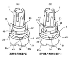
- the perspective view which shows the positional relationship corresponding to the time of unfolding use of the rotation piece inserted in the shaft, and folding storage by (A) and (B).
- wire of FIG. 4 (B) which shows the depression engagement process of the protrusion part of a rotation control piece and a rotation control groove
- the perspective view which expands and shows the principal part of 2nd Embodiment of this invention.
- Fig. 1 shows the arrangement of the door mirror on the left side of the vehicle.
- the door mirror of this embodiment shown in FIG. 1 includes a door mirror base 1 fixed to a vehicle side, specifically, a door side D of a front door, a shaft 2 fixed to the door mirror base 1, and the shaft 2.
- a door mirror unit 3 rotatably supported by the door mirror base 1.
- the door mirror unit 3 is shown with only the bracket 32 by removing the internal functional parts such as the mirror main body and the housing 31 shown in FIG.
- the door mirror base 1, the shaft 2, the housing 31 of the door mirror unit 3, and the bracket 32 are all made of an appropriate synthetic resin.
- the door mirror base 1 includes an attachment part 11 that is fastened and fixed to the door side D, and an arm part 12 that projects substantially horizontally from the attachment part 11 to the side and supports the door mirror unit 3 via the shaft 2. Yes.
- the shaft 2 is sub-assembled to the door mirror unit 3 and its lower end is fixed to the arm portion 12 of the door mirror base 1.
- a bearing portion 33 having a shaft insertion hole 34 is provided at one end of the bracket 32 of the door mirror unit 3.
- the outer periphery of the bearing portion 33 is formed in a substantially semicircular shape concentric with the shaft insertion hole 34.
- a substantially annular shape set to a required groove width by an outer peripheral wall 35 formed on the substantially semicircular outer periphery and an inner peripheral wall 36 formed on the hole edge of the shaft insertion hole 34.
- the rotation restricting groove 37 is formed.
- the rotation restricting groove 37 is separated in a fan shape by a groove stopper end wall 37a that defines the folding storage position P1 of the door mirror unit 3 and a groove stopper end wall 37 that defines the maximum unfolded position P3. It is made.
- the shaft 2 is erected integrally on a standing base surface 22 that forms the upper surface of a substantially cylindrical base portion 21 that is open on the lower side, and is inserted from the lower side of the bracket 32 into the bearing hole 34. It is.
- a plurality of boss portions 21 a are projected from the inside of the base portion 21, and the boss portions 21 a are fastened and fixed onto the arm portion 12 of the door mirror base 1.
- the rotation restricting piece 23 that engages with the rotation restricting groove 37 on the lower surface of the bearing portion 33 is erected integrally along the periphery of the standing base surface 22 on the lower surface of the shaft 2.
- the folding storage position P1 of the door mirror unit 3 is defined by one groove stop end wall 37a of the rotation restriction groove 37 of the bracket 22 being locked to one side edge of the rotation restriction piece 23, and the other.
- the groove stop end wall 37 is engaged with the other side edge of the rotation restricting piece 23, the maximum unfolded position P3 is defined.
- a ring-shaped rotating piece 4 is movably inserted and arranged in the circumferential direction and the axial direction at the base of the shaft 2.
- the rotating piece 4 is made of an appropriate synthetic resin like the shaft 2 and the bracket 32, etc., and is provided on the inner periphery of the ring with a lower edge of the shaft insertion hole 34 of the bearing portion 33 and an inner peripheral wall 36 that follows this.
- a collar 41 that is in sliding contact is formed integrally.
- a plurality of locking projections 42 are intermittently and integrally provided in the circumferential direction across the base portion of the collar 41, A plurality of notches 38 with which the protrusions 42 are engaged are intermittently formed in the circumferential direction.
- the rotating piece 4 can rotate integrally with the bracket 32 with respect to the shaft 2 in a state where the locking projection 42 and the notch 38 are engaged.
- a plurality of protruding edge portions 43 are provided in the circumferential direction on the lower surface of the ring of the rotating piece 4, while the door mirror unit 3 is folded on the standing base surface 22 of the shaft 2 from the folding storage position P ⁇ b> 1 in the unfolding direction.
- a concave portion 24 is provided for the projecting edge portion 43 to drop and engage from the standing base surface 22 to define the deployment use position P2 when it is rotated.
- the projecting edge 43 and the recess 24 both have a circumferential edge that is slanted so that both can be easily engaged and disengaged in the circumferential direction.
- the upper end portion of the shaft 2 protruding from the bearing portion 33 is elastically mounted with the coil spring 5 compressed.
- the coil spring 5 constitutes the rotational moderation mechanism 6 of the door mirror unit 3 together with the rotating piece 4 described above, and holds the pressing force of the bearing portion 33 and the rotating piece 4 against the standing base surface 22 of the shaft 2;
- the door mirror unit 3 functions to prevent rattling, and is elastically mounted between a washer 7 disposed on the upper surface of the bearing portion 33 and a push nut 8 fitted and engaged with the upper end of the shaft 2. .
- the door mirror unit 3 is manually operated with respect to the door mirror base 1, the folding storage position P1 in which the mirror surface faces the door side around the shaft 2, and the mirror surface by changing the phase from the folding storage position P1 to a required angle. Is rotatable to a deployment use position P2 facing the rear of the vehicle.
- Protrusions 25 and 39 are provided to hold the folding storage position P1 by overriding and engaging with each other in the course of rotation from to the folding storage position P1.
- the protrusion 25 of the rotation restricting piece 23 has an upper edge on the edge side where the rotation restricting piece 23 is engaged with a groove stop end wall 37 a that defines the folding storage position P ⁇ b> 1 in the rotation restricting groove 37. Is formed.
- the protrusion 39 on the side of the rotation restricting groove 37 is formed on the upper surface of the groove at a position corresponding to the length of the protrusion 25 from the groove stop wall 37a.
- the door mirror unit 3 moves slightly up on the axis of the shaft 2 together with the rotating piece 4 against the spring force of the coil spring 5 of the rotational moderation mechanism 6, so Allow to ride.
- the folding storage position P1 of the door mirror unit 3 is firmly held by the mutual engagement of the protrusions 25 and 39 and the spring force of the coil spring 5.
- the projecting portions 25 and 39 get over and engage with each other so that a click feeling can be obtained, so that the rotation operation to the proper folding storage position P1 is performed. It is possible to perceive, and it is also possible to avoid inducing a storage operation failure.
- the engagement between the protruding edge portion 43 of the rotating piece 4 and the concave portion 24 of the standing base surface 22 of the shaft 2 is essentially the same as the posture maintenance at the deployed use position P2.
- the folding use position P1 from the deployment use position P2 to the upper edge of the rotation restriction piece 23 of the shaft 2 and the groove upper surface of the rotation restriction groove 37 of the bearing portion 33, respectively.
- Protrusions 25 and 39 are provided to get over and engage with each other during the rotation process.
- the combined structure can be easily established by design, and a high-quality vehicle door mirror can be obtained.
- FIG. 7 shows a second embodiment of the present invention.
- the concave portion 44 is provided in the central portion of the lower edge of the projecting edge portion 43 in the first embodiment.
- a locking projection 26 is provided in which the concave portion 44 of the protruding edge 43 falls and engages at the folding storage position P ⁇ b> 1 of the door mirror unit 3.
- the concave portion 44 of the projection 43 and the latching projection 26 of the standing base surface 22 corresponding to the projection 44 have a slight size in structure, their locking force is sufficient.
- the effect of suppressing the rotation of the door mirror unit 3 in the unfolding direction at the folding storage position P1 can be enhanced.
- manual storage type door mirror is illustrated in the above embodiment, it can be applied to an electric storage type door mirror.
Landscapes
- Engineering & Computer Science (AREA)
- Multimedia (AREA)
- Mechanical Engineering (AREA)
- Rear-View Mirror Devices That Are Mounted On The Exterior Of The Vehicle (AREA)
Abstract
Description
11 アタッチメント部
12 アーム部
2 シャフト
21 ベース部
22 立設基部面
23 回動規制片
24 凹部
25 突起部
26 係止突起
3 ドアミラーユニット
31 ハウジング
32 ブラケット
33 軸受部
34 シャフト挿通孔
37 回動規制溝
39 突起部
4 回動駒
43 突縁部
44 凹部
5 コイルスプリング(スプリング)
6 回転節度機構
D ドアサイド(車体側部)
P1 折り畳み格納位置
P2 展開使用位置
P3 最大展開位置
Claims (3)
- 車両側部に固定されるドアミラーベースと、該ドアミラーベースに固定されるシャフトと、該シャフトを中心に軸受部を介して折り畳み格納位置と展開使用位置とに回動可能なドアミラーユニットと、を備え、
前記軸受部は、その下面側に略環状の回動規制溝を備えて、該回動規制溝に前記シャフトに設けた回動規制片を係合配置し、これらシャフトと軸受部との相互に前記ドアミラーユニットの展開使用位置を保持させる回転節度機構を設けた構造であって、
前記回動規制片の上縁と、これに対向した前記回動規制溝の溝上面とのそれぞれに、前記ドアミラーユニットの展開使用位置から折り畳み格納位置への回動過程で相互に乗り越えて落ち込み係合し、該折り畳み格納位置を保持する突起部を設けたことを特徴とする車両用ドアミラー。 - 前記回転節度機構は、前記シャフトに可動的に嵌挿配置され、前記軸受部に対しては回動が拘束されたリング状の回動駒と、該回動駒を前記シャフトの立設基部面に押圧するスプリングと、を備え、
前記回動駒の下面に設けた突縁部と、前記シャフトの立設基部面に設けた凹部とが、前記ドアミラーユニットの展開使用位置で相互に落ち込み係合可能としたことを特徴とする請求項1に記載の車両用ドアミラー。 - 前記回動駒の突縁部の下縁に凹部を設ける一方、前記シャフトの立設基部面に、前記ドアミラーユニットの折り畳み格納位置で前記突縁部の凹部が落ち込み係合する係止突起を設けたことを特徴とする請求項2に記載の車両用ドアミラー。
Priority Applications (4)
| Application Number | Priority Date | Filing Date | Title |
|---|---|---|---|
| US15/309,581 US9925923B2 (en) | 2014-05-09 | 2014-05-09 | Vehicular door mirror |
| PCT/JP2014/062484 WO2015170404A1 (ja) | 2014-05-09 | 2014-05-09 | 車両用ドアミラー |
| CN201480078677.5A CN106458098B (zh) | 2014-05-09 | 2014-05-09 | 车辆用车门反光镜 |
| EP14891440.1A EP3141429B1 (en) | 2014-05-09 | 2014-05-09 | Vehicular door mirror |
Applications Claiming Priority (1)
| Application Number | Priority Date | Filing Date | Title |
|---|---|---|---|
| PCT/JP2014/062484 WO2015170404A1 (ja) | 2014-05-09 | 2014-05-09 | 車両用ドアミラー |
Publications (1)
| Publication Number | Publication Date |
|---|---|
| WO2015170404A1 true WO2015170404A1 (ja) | 2015-11-12 |
Family
ID=54392272
Family Applications (1)
| Application Number | Title | Priority Date | Filing Date |
|---|---|---|---|
| PCT/JP2014/062484 Ceased WO2015170404A1 (ja) | 2014-05-09 | 2014-05-09 | 車両用ドアミラー |
Country Status (4)
| Country | Link |
|---|---|
| US (1) | US9925923B2 (ja) |
| EP (1) | EP3141429B1 (ja) |
| CN (1) | CN106458098B (ja) |
| WO (1) | WO2015170404A1 (ja) |
Families Citing this family (1)
| Publication number | Priority date | Publication date | Assignee | Title |
|---|---|---|---|---|
| US11230228B2 (en) | 2017-05-24 | 2022-01-25 | SMR Patents S.à.r.l. | Pivot detent system and rear view device therewith |
Citations (3)
| Publication number | Priority date | Publication date | Assignee | Title |
|---|---|---|---|---|
| US6390630B1 (en) * | 2000-02-29 | 2002-05-21 | Bühler Motor GmbH | Outside rear view mirror for a motor vehicle |
| JP2003335176A (ja) * | 2002-05-21 | 2003-11-25 | Ichikoh Ind Ltd | 車両用サイドミラー |
| JP2007083839A (ja) * | 2005-09-21 | 2007-04-05 | Tokai Rika Co Ltd | 車両用ミラー装置 |
Family Cites Families (6)
| Publication number | Priority date | Publication date | Assignee | Title |
|---|---|---|---|---|
| JP2008143357A (ja) * | 2006-12-11 | 2008-06-26 | Tokai Rika Co Ltd | 車両用ミラー装置 |
| JP4847311B2 (ja) * | 2006-12-25 | 2011-12-28 | 株式会社東海理化電機製作所 | 車両用ミラー装置 |
| JP2011121560A (ja) | 2009-12-14 | 2011-06-23 | Mitsuba Corp | ドアミラー、およびドアミラーの製造方法 |
| JP6019664B2 (ja) * | 2012-03-28 | 2016-11-02 | 市光工業株式会社 | 車両用アウトサイドミラー装置 |
| CN202656933U (zh) * | 2012-06-19 | 2013-01-09 | 三多乐精密注塑(深圳)有限公司 | 汽车后视镜折叠装置 |
| JP6083274B2 (ja) * | 2013-03-19 | 2017-02-22 | 市光工業株式会社 | 車両用ドアミラー |
-
2014
- 2014-05-09 EP EP14891440.1A patent/EP3141429B1/en active Active
- 2014-05-09 US US15/309,581 patent/US9925923B2/en active Active
- 2014-05-09 CN CN201480078677.5A patent/CN106458098B/zh not_active Expired - Fee Related
- 2014-05-09 WO PCT/JP2014/062484 patent/WO2015170404A1/ja not_active Ceased
Patent Citations (3)
| Publication number | Priority date | Publication date | Assignee | Title |
|---|---|---|---|---|
| US6390630B1 (en) * | 2000-02-29 | 2002-05-21 | Bühler Motor GmbH | Outside rear view mirror for a motor vehicle |
| JP2003335176A (ja) * | 2002-05-21 | 2003-11-25 | Ichikoh Ind Ltd | 車両用サイドミラー |
| JP2007083839A (ja) * | 2005-09-21 | 2007-04-05 | Tokai Rika Co Ltd | 車両用ミラー装置 |
Also Published As
| Publication number | Publication date |
|---|---|
| EP3141429B1 (en) | 2019-08-14 |
| US20170151911A1 (en) | 2017-06-01 |
| CN106458098B (zh) | 2019-12-31 |
| CN106458098A (zh) | 2017-02-22 |
| US9925923B2 (en) | 2018-03-27 |
| EP3141429A4 (en) | 2017-12-27 |
| EP3141429A1 (en) | 2017-03-15 |
Similar Documents
| Publication | Publication Date | Title |
|---|---|---|
| US7594819B2 (en) | Rotary connector | |
| US8845000B2 (en) | Vehicle sun visor | |
| JP5579685B2 (ja) | 車両用ミラー装置 | |
| WO2017031953A1 (zh) | 用于汽车外后视镜的电动折叠装置 | |
| US20170361801A1 (en) | Mounting structure for driver-seat airbag device | |
| WO2019208085A1 (ja) | ステアリングホイール | |
| JP7159075B2 (ja) | ステアリングホイール | |
| US8931822B2 (en) | Vehicle sun visor | |
| JP2006120512A (ja) | 回転コネクタ | |
| JP6083274B2 (ja) | 車両用ドアミラー | |
| JP2019199163A5 (ja) | ||
| WO2015170404A1 (ja) | 車両用ドアミラー | |
| US11760175B2 (en) | Winding shade device | |
| JP5778627B2 (ja) | ロータリースイッチ装置 | |
| JP2007083839A (ja) | 車両用ミラー装置 | |
| CN205344701U (zh) | 一种新型外后视镜折叠结构 | |
| JP2015534916A5 (ja) | ||
| JP6382581B2 (ja) | 電動格納ユニットのギヤ構造 | |
| JP2015020493A (ja) | 車両用ミラー装置 | |
| JP2013237373A (ja) | 車両用ドアミラー | |
| JP6373134B2 (ja) | 回転コネクタ装置 | |
| JP2017105312A (ja) | ワンウェイクラッチおよび乗物用シート | |
| JP6309394B2 (ja) | 車両用視認装置 | |
| JP6639045B2 (ja) | 巻線装置用ワーク支持具 | |
| JP2016081639A (ja) | ステアリングロールコネクタ |
Legal Events
| Date | Code | Title | Description |
|---|---|---|---|
| 121 | Ep: the epo has been informed by wipo that ep was designated in this application |
Ref document number: 14891440 Country of ref document: EP Kind code of ref document: A1 |
|
| REEP | Request for entry into the european phase |
Ref document number: 2014891440 Country of ref document: EP |
|
| WWE | Wipo information: entry into national phase |
Ref document number: 15309581 Country of ref document: US Ref document number: 2014891440 Country of ref document: EP |
|
| NENP | Non-entry into the national phase |
Ref country code: DE |
|
| NENP | Non-entry into the national phase |
Ref country code: JP |