WO2015170521A1 - 撮像装置 - Google Patents
撮像装置 Download PDFInfo
- Publication number
- WO2015170521A1 WO2015170521A1 PCT/JP2015/058838 JP2015058838W WO2015170521A1 WO 2015170521 A1 WO2015170521 A1 WO 2015170521A1 JP 2015058838 W JP2015058838 W JP 2015058838W WO 2015170521 A1 WO2015170521 A1 WO 2015170521A1
- Authority
- WO
- WIPO (PCT)
- Prior art keywords
- display
- main body
- state
- viewfinder
- display unit
- Prior art date
- Legal status (The legal status is an assumption and is not a legal conclusion. Google has not performed a legal analysis and makes no representation as to the accuracy of the status listed.)
- Ceased
Links
Images


Classifications
-
- H—ELECTRICITY
- H04—ELECTRIC COMMUNICATION TECHNIQUE
- H04N—PICTORIAL COMMUNICATION, e.g. TELEVISION
- H04N23/00—Cameras or camera modules comprising electronic image sensors; Control thereof
- H04N23/60—Control of cameras or camera modules
- H04N23/63—Control of cameras or camera modules by using electronic viewfinders
- H04N23/633—Control of cameras or camera modules by using electronic viewfinders for displaying additional information relating to control or operation of the camera
-
- H—ELECTRICITY
- H04—ELECTRIC COMMUNICATION TECHNIQUE
- H04N—PICTORIAL COMMUNICATION, e.g. TELEVISION
- H04N23/00—Cameras or camera modules comprising electronic image sensors; Control thereof
- H04N23/50—Constructional details
- H04N23/53—Constructional details of electronic viewfinders, e.g. rotatable or detachable
- H04N23/531—Constructional details of electronic viewfinders, e.g. rotatable or detachable being rotatable or detachable
-
- G—PHYSICS
- G03—PHOTOGRAPHY; CINEMATOGRAPHY; ANALOGOUS TECHNIQUES USING WAVES OTHER THAN OPTICAL WAVES; ELECTROGRAPHY; HOLOGRAPHY
- G03B—APPARATUS OR ARRANGEMENTS FOR TAKING PHOTOGRAPHS OR FOR PROJECTING OR VIEWING THEM; APPARATUS OR ARRANGEMENTS EMPLOYING ANALOGOUS TECHNIQUES USING WAVES OTHER THAN OPTICAL WAVES; ACCESSORIES THEREFOR
- G03B13/00—Viewfinders; Focusing aids for cameras; Means for focusing for cameras; Autofocus systems for cameras
- G03B13/02—Viewfinders
- G03B13/06—Viewfinders with lenses with or without reflectors
-
- G—PHYSICS
- G03—PHOTOGRAPHY; CINEMATOGRAPHY; ANALOGOUS TECHNIQUES USING WAVES OTHER THAN OPTICAL WAVES; ELECTROGRAPHY; HOLOGRAPHY
- G03B—APPARATUS OR ARRANGEMENTS FOR TAKING PHOTOGRAPHS OR FOR PROJECTING OR VIEWING THEM; APPARATUS OR ARRANGEMENTS EMPLOYING ANALOGOUS TECHNIQUES USING WAVES OTHER THAN OPTICAL WAVES; ACCESSORIES THEREFOR
- G03B15/00—Special procedures for taking photographs; Apparatus therefor
-
- G—PHYSICS
- G03—PHOTOGRAPHY; CINEMATOGRAPHY; ANALOGOUS TECHNIQUES USING WAVES OTHER THAN OPTICAL WAVES; ELECTROGRAPHY; HOLOGRAPHY
- G03B—APPARATUS OR ARRANGEMENTS FOR TAKING PHOTOGRAPHS OR FOR PROJECTING OR VIEWING THEM; APPARATUS OR ARRANGEMENTS EMPLOYING ANALOGOUS TECHNIQUES USING WAVES OTHER THAN OPTICAL WAVES; ACCESSORIES THEREFOR
- G03B17/00—Details of cameras or camera bodies; Accessories therefor
- G03B17/02—Bodies
- G03B17/04—Bodies collapsible, foldable or extensible, e.g. book type
-
- G—PHYSICS
- G03—PHOTOGRAPHY; CINEMATOGRAPHY; ANALOGOUS TECHNIQUES USING WAVES OTHER THAN OPTICAL WAVES; ELECTROGRAPHY; HOLOGRAPHY
- G03B—APPARATUS OR ARRANGEMENTS FOR TAKING PHOTOGRAPHS OR FOR PROJECTING OR VIEWING THEM; APPARATUS OR ARRANGEMENTS EMPLOYING ANALOGOUS TECHNIQUES USING WAVES OTHER THAN OPTICAL WAVES; ACCESSORIES THEREFOR
- G03B17/00—Details of cameras or camera bodies; Accessories therefor
- G03B17/18—Signals indicating condition of a camera member or suitability of light
- G03B17/20—Signals indicating condition of a camera member or suitability of light visible in viewfinder
-
- H—ELECTRICITY
- H04—ELECTRIC COMMUNICATION TECHNIQUE
- H04N—PICTORIAL COMMUNICATION, e.g. TELEVISION
- H04N23/00—Cameras or camera modules comprising electronic image sensors; Control thereof
- H04N23/60—Control of cameras or camera modules
- H04N23/64—Computer-aided capture of images, e.g. transfer from script file into camera, check of taken image quality, advice or proposal for image composition or decision on when to take image
-
- H—ELECTRICITY
- H04—ELECTRIC COMMUNICATION TECHNIQUE
- H04N—PICTORIAL COMMUNICATION, e.g. TELEVISION
- H04N23/00—Cameras or camera modules comprising electronic image sensors; Control thereof
- H04N23/60—Control of cameras or camera modules
- H04N23/667—Camera operation mode switching, e.g. between still and video, sport and normal or high- and low-resolution modes
-
- H—ELECTRICITY
- H04—ELECTRIC COMMUNICATION TECHNIQUE
- H04N—PICTORIAL COMMUNICATION, e.g. TELEVISION
- H04N23/00—Cameras or camera modules comprising electronic image sensors; Control thereof
- H04N23/60—Control of cameras or camera modules
- H04N23/61—Control of cameras or camera modules based on recognised objects
Definitions
- the present disclosure relates to an imaging apparatus suitable for a small digital still camera (DSC) or the like.
- DSC small digital still camera
- An imaging device has been proposed in which the viewfinder can be folded along the main body or stored inside the main body in consideration of downsizing when carried (for example, refer to Patent Document 1 or 2).
- a user uses the viewfinder by pulling it forward.
- an imaging device having a display panel that displays information related to shooting in an icon form or displays a so-called live view image or captured image is known.
- a display panel is rotatably attached to the main body. For example, it is known that the state of the display panel can be changed with respect to the main body between a first rotation state in which the display surface faces the back side and a second rotation state in which the display surface faces the front side. It has been.
- the image pickup person is photographed with the image pickup lens in the direction of the image pickup person himself by setting the display surface of the display panel in the second rotation state facing the front side. You can easily take a “selfie”.
- the imaging apparatus main body is photographed from a landscape orientation to a portrait orientation.
- the orientation of the display panel or the main body can be changed to various modes, it is desirable to appropriately display the position and arrangement of icons and the like displayed on the display panel according to the shooting situation.
- An imaging apparatus is rotatable with respect to a main body and a first state in which a display surface faces the back side and a second state in which the display surface faces the front side with respect to the main body.
- the display unit includes a display control unit that changes an arrangement state of a predetermined icon displayed on the display unit according to the posture of the main body.
- the arrangement state of predetermined icons displayed on the display unit changes according to the posture of the main body.
- the imaging device when the display surface of the display unit faces the front side, the arrangement state of the predetermined icon displayed on the display unit is changed according to the posture of the main body. Therefore, it is possible to display appropriate information according to the shooting situation.
- the effects described here are not necessarily limited, and may be any of the effects described in the present disclosure.
- FIG. 2 is a perspective view illustrating a state in which a viewfinder is protruded upward from a storage position in the imaging apparatus illustrated in FIG. 1.
- FIG. 5 is a perspective view illustrating a state in which the viewfinder is moved to the rear (back side) of the main body to be in a use position in the imaging apparatus illustrated in FIG. 4.
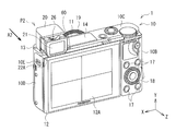
- FIG. 1 illustrates a configuration of an imaging device 1 according to an embodiment of the present disclosure as viewed from the front.
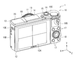
- FIG. 2 shows a configuration of the imaging apparatus 1 as viewed from the rear.
- the imaging apparatus 1 is, for example, a small digital single-lens camera, and includes a main body 10 and a viewfinder 20.
- the viewfinder 20 is stored in the storage position P1 inside the main body 10 when not in use, and protrudes (pops up) to the use position P2 outside the main body 10 when used.
- the main body 10 has, for example, a horizontally long, substantially rectangular parallelepiped shape, and has a front surface 10A, a back surface 10B, an upper surface 10C, and a side surface 10D.
- a body mount 11 is provided on the front surface 10 ⁇ / b> A of the main body 10.
- various control system circuits such as an image sensor 112 and a signal processing unit 102 shown in FIG.
- a viewfinder operation unit 10E for popping up the viewfinder 20 is provided on the side surface 10D of the main body 10.
- a power button 15 and a shutter button 16 are provided on the upper surface 10 ⁇ / b> C of the main body 10.
- a display unit 12 is provided on the back surface 10 ⁇ / b> B of the main body 10.
- a plurality of operation buttons 17 and a control wheel 18 are also provided on the back surface 10 ⁇ / b> B of the main body 10.
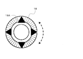
- the control wheel 18 may be one of the direction selection units that can select the display content of the display unit 12 according to the operation direction.
- the control wheel 18 may have a function as the operation button 18 ⁇ / b> A in the vertical and horizontal directions.
- the control wheel 18 may also be one of ring-shaped operation units that can change the operation direction clockwise and counterclockwise.
- display contents such as predetermined shooting information displayed on the display unit 12 may be selectable depending on the operation direction of the control wheel 18.
- An eye sensor 60 is also provided in the vicinity of the viewfinder 20 on the back surface 10B of the main body 10.
- the eye sensor 60 detects, for example, whether or not the user (imager) is looking into the viewfinder 20 with a magnetic sensor.
- the front side is the front side of the main body 10, and is the lens side and the subject side in the front-rear direction Z of the main body 10.
- the rear side is the back side of the main body 10.
- the front-rear direction Z may be the same as the optical axis direction of the imaging lens 111 shown in FIG.
- the left-right direction of the main body 10 is the X direction
- the vertical direction of the main body 10 is the Y direction. The same applies to other figures thereafter.
- the body mount 11 performs mechanical or electrical connection between the main body 10 and an interchangeable imaging lens 111 shown in FIG. 12 to be described later.
- the user selects the interchangeable imaging lens 111 according to the application. Thus, it can be connected to the main body 10.
- the body mount 11 is covered with a cap 11A.
- the body mount 11 is also provided with a control ring 19.
- the control ring 19 may be one of the direction selection units that can select the display content of the display unit 12 according to the operation direction.
- the control ring 19 may be one of ring-shaped operation units that can change the operation direction clockwise and counterclockwise. For example, display contents such as predetermined shooting information displayed on the display unit 12 can be selected according to the operation direction of the control ring 19.
- the viewfinder 20 is used for visually confirming a photographed image and performing composition setting, focusing, and the like, and is configured by an OVF (optical viewfinder) or an EVF (electronic viewfinder).
- OVF optical viewfinder
- EVF electronic viewfinder
- an eyepiece (not shown), a liquid crystal, an organic EL (Electro-Luminescence), and the like are located behind the viewing window 21 (not shown in FIGS. 1 to 3, see FIG. 7).
- Display screen (not shown).
- the viewfinder 20 is movable in two or more directions between a storage position P1 stored in the main body 10 and a use position P2 protruding outside the main body 10. Thereby, in this imaging device 1, size reduction is possible.
- the viewfinder 20 is preferably movable in two directions orthogonal to each other. Specifically, the viewfinder 20 extends (protrudes) upward from the main body 10 as shown by an arrow A1 in FIGS. 4 and 5 from the storage position P1 (see FIGS. 1 to 3). As shown by an arrow A2 in FIGS. 6 and 7, it is preferable that the main body 10 is advanced rearward (in the eyepiece direction) to reach the use position P2. By causing the viewfinder 20 to protrude above the main body 10, the use position P ⁇ b> 2 is positioned above the main body 10.
- the viewfinder 20 can be brought close to the configuration of a normal digital single-lens camera positioned above the lens barrel and the display unit 12, and the usability for the user can be improved. Further, by moving the viewfinder 20 to the rear of the main body 10, the clearance to the eyes can be reduced and the light shielding property can be improved.
- the eyepiece 22 ⁇ / b> A of the viewfinder 20 is preferably protruded rearward from the back surface 10 ⁇ / b> B (display unit 12) of the main body 10.
- the clearance with the eyes is reduced, and the possibility that the user's nose hits the display unit 12 is reduced, and the usability is improved.
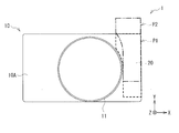
- the main body 10 preferably has an opening 13 through which the viewfinder 20 enters and exits the main body 10 on the upper surface 10C.
- the opening 13 is provided on the back surface 10B of the main body 10
- the lens barrel becomes smaller, thereby reducing the magnification and brightness. It is dark and the size of the image sensor is small. Further, the size of the display unit 12 is also reduced.
- the position of the opening 13 shown in FIGS. 1 to 3 is a place where a strobe is arranged in a normal digital single-lens camera.
- the arrangement of the strobe 14 is changed and arranged at a position closer to the center than the opening 13.
- the viewfinder 20 is preferably provided avoiding the body mount 11 as shown in FIG. 3 described above. Thereby, it is possible to avoid interference between the viewfinder 20 and the lens barrel. Note that the viewfinder 20 may overlap the display unit 12 in the rear view.
- the viewfinder 20 is provided with a diopter adjustment unit 26 (see FIGS. 6 and 7).
- the diopter adjustment unit 26 is an operation unit (lever, knob, dial, etc.) for adjusting the power of the viewfinder 20 in accordance with the visual acuity of the user.
- the diopter adjustment unit 26 is preferably provided on the upper surface of the viewfinder unit constituting the viewfinder 20.
- the diopter adjustment unit 26 is concealed in the main body 10 at the storage position P1 (see FIGS. 1 to 3), and is exposed and operable at the use position P2 (see FIGS. 6 and 7). Is preferred. By limiting access to the diopter adjustment unit 26 in this way, it is possible to avoid unintentionally operating the diopter adjustment unit 26 and changing settings.
- the projection amount of the diopter adjustment unit 26 from the upper surface of the viewfinder unit is reduced, and the possibility that the setting is reset even when the viewfinder 20 is returned from the use position P2 to the storage position P1 is reduced. Therefore, it is possible to save the trouble of re-adjusting the diopter adjustment unit 26 every time it is used, and to improve the convenience for the user.
- the display unit 12 is constituted by a liquid crystal panel, for example.
- the display unit 12 can display various predetermined shooting information related to shooting.
- the predetermined shooting information may be a live view image or an icon-like display of the subject 2 as shown in FIG.
- various menu displays related to device settings, electronic level, and the like may be displayed.
- the display unit 12 is in a first state where the display surface 12 ⁇ / b> A faces the back side and a second state where the display surface 12 ⁇ / b> A faces the front side with respect to the main body 10. It can be turned. For example, as shown in FIG. 8, the display unit 12 is rotated 180 degrees around an upper side of the main body 10.
- so-called “self-portrait” can be easily performed in which the imaging lens 111 (FIG. 12) is directed toward the imaging person himself and the imaging person himself is imaged.
- the photographer can take a picture while checking the through image of the subject 2 including himself / herself on the display unit 12.
- this imaging device 1 when taking a self-portrait, etc., according to the photographer's preference, as shown in the upper part of FIG. As shown, it is possible to appropriately select shooting with the main body 10 in a vertically oriented position.
- FIG. 12 shows a configuration example of the control system circuit of the imaging apparatus 1.
- the imaging device 1 includes a control unit 101, a signal processing unit 102, a display control unit 103, an image recording unit 104, an operation unit 105, and a detection unit 106 as control system circuits.
- the imaging device 1 further includes an imaging unit 110 including an imaging lens 111 and an imaging element 112, and a lens driving unit 113.
- the detection unit 106 includes an eye sensor 60, a display unit rotation detection unit 107, and a posture detection unit 108.
- the imaging lens 111 forms an optical subject image on the image sensor 112.
- the imaging lens 111 has a plurality of lenses, and by moving the lenses, optical zoom magnification, focus adjustment, and the like are possible.
- the image sensor 112 forms an object image on the light receiving surface through the image pickup lens 111 and generates an electric signal by photoelectric conversion, and is configured by, for example, a CMOS (Complementary Metal Metal Oxide Semiconductor) image sensor.
- the lens driving unit 113 drives the lens of the imaging lens 111 for adjusting the optical zoom magnification, the F value, and the focus.
- the signal processing unit 102 performs various kinds of signal processing on the image pickup signal output from the image pickup device 112, and generates image data to be displayed on the viewfinder 20 and the display unit 12 and image data to be recorded by the image recording unit 104. Is what you do.
- the image recording unit 104 records image data on a recording medium inside the main body (not shown) or an external recording medium.
- the operation unit 105 includes the power button 15, the shutter button 16, the operation button 17, the control wheel 18, the operation button 18A, and the control ring 19 shown in FIGS.
- the control unit 101 performs overall control of each unit of the imaging apparatus 1.
- the control unit 101 has a function as an imaging control unit that performs control according to the shooting mode.
- As one of the shooting modes for example, there is a self-timer mode in which an actual imaging process is executed after a predetermined time has elapsed since an imaging start instruction was issued.
- the display control unit 103 performs display control on the viewfinder 20 and the display unit 12. For example, the display control unit 103 performs display control of various shooting information displayed on the viewfinder 20 and the display unit 12 regarding shooting. For example, as shown in FIG. 13, the live view image and icon-like display of the subject 2 are controlled. In addition, various menu displays related to the setting of the device and display control of an electronic level or the like are performed.
- the display control unit 103 executes display control for displaying characters, images, and other various information on the display unit 12 based on the control of the control unit 101.
- the display unit 12 displays characters, images, and other various information whose display is controlled by the display control unit 103.
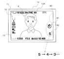
- FIG. 13 shows an example in which the icon group 71, icon group 72, icon group 73, self-timer icon 80 and live view image of the subject 2 are displayed on the display unit 12.
- the self-timer icon 80 may include a shooting mode icon 81 indicating that the shooting mode is the self-timer mode, and a countdown icon 82 indicating the passage of time during the self-timer mode.
- the countdown icon 82 displays, for example, the passage of time in units of seconds in a countdown format.
- the display unit rotation detection unit 107 has a sensor for detecting the state of the display unit 12.
- the display unit rotation detection unit 107 detects at least whether the display unit 12 is in the first state (the direction of the display surface 12A is the back side) or the second state (the direction of the display surface 12A is the front side). It is like that.
- the posture detection unit 108 has a sensor for detecting the posture of the main body 10 of the imaging apparatus 1.
- the sensor for detecting the posture of the main body 10 include an acceleration sensor and a gyro sensor.
- the angle of the main body 10 may be detected by an angle sensor or a so-called vertical / horizontal sensor.
- the posture detection unit 108 detects at least whether the main body 10 is in a horizontal posture position or a vertical posture position.
- the posture detection unit 108 also detects a horizontal position when the electronic level is used.
- the imaging apparatus 1 operates as follows.
- This imaging apparatus 1 can take a picture while confirming the composition of the subject 2 with the viewfinder 20 or the display unit 12.
- the imaging apparatus 1 can be turned on / off by operating the power button 15.
- the power can be automatically turned on / off according to the pop-up operation of the viewfinder 20.
- the viewfinder 20 is stored in the storage position P1 in the main body 10 when not in use (see FIGS. 1 to 3).
- the viewfinder unit constituting the viewfinder 20 pops up outside the main body 10 (see FIGS. 4 and 5).
- the diopter adjustment unit 26 is exposed and can be operated.
- the viewfinder 20 is movable in two or more directions between a storage position P1 stored in the main body 10 and a use position P2 protruding outside the main body 10. Therefore, the opening 13 through which the viewfinder 20 enters and exits the main body 10 can be provided in addition to the back surface 10B of the main body 10, and the main body 10 can be reduced in size while corresponding to an increase in the diameter of the lens barrel and an increase in the screen of the display section 12. Can be realized.
- the state where the viewfinder 20 protrudes upward may be a state where the viewfinder 20 protrudes only above the main body 10 (in the direction of arrow A1 in FIGS. 4 and 5).
- the eyepiece surface 22 ⁇ / b> A may advance from the state to the back side of the main body 10 (in the direction of arrow A ⁇ b> 2 in FIGS. 6 and 7).
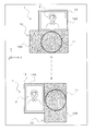
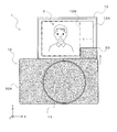
- FIG. 14 shows an example of the display area when the display unit 12 is in the second state and the viewfinder 20 protrudes upward.
- the display control unit 103 includes the viewfinder 20 as viewed from the front side as shown in FIG. A region other than the portion overlapping the display unit 12 may be used as the display area 12B. In this display area 12B, a live view image of the subject 2 or an icon may be displayed.
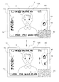
- FIG. 15 shows an example of icon display when the display unit 12 is in the second state and the viewfinder 20 protrudes upward.
- the display control unit 103 is viewed from the front side as shown in the lower part of FIG.
- a plurality of icons may be displayed in a region other than the portion where the finder 20 and the display unit 12 overlap.
- the display position may be moved so that the self-timer icon 80 and the icon group 73 do not overlap the viewfinder 20 when viewed from the front side, as in the display state in the upper part from the display state in the upper part in FIG. .
- the display control unit 103 may change the arrangement state with some of the plurality of icons as predetermined icons according to the attitude of the main body 10. In this case, the display control unit 103 may change at least one of the directions or positions of some icons as the arrangement state.
- FIG. 16 shows an example of icon display when the display unit 12 is in the second state and the main body 10 is in the vertical posture position (see the lower part of FIG. 11).
- the display control unit 103 displays a plurality of icons, for example, as shown in FIG.
- the first arrangement state may be all in the same direction.
- the display control unit 103 displays only some icons as shown in FIG. May be changed to the second arrangement state as a predetermined icon.
- the direction of the self-timer icon 80 (the shooting mode icon 81 and the countdown icon 82) is set to a vertical orientation in accordance with the posture position of the main body 10 as a predetermined icon with respect to the display example of FIG. 13. It is changing.
- FIG. 17 shows an example of icon display when the display unit 12 is in the second state and the main body 10 is in the vertical posture position and the viewfinder 20 protrudes upward.
- the display control unit 103 as shown in FIG.
- a plurality of icons may be displayed in a region other than the portion where the display unit 12 and the display unit 12 overlap.
- the display position is moved so that the self-timer icon 80 and the icon group 73 do not overlap the viewfinder 20 when viewed from the front side, compared to the display example of FIG.
- FIG. 18 shows another display example of the icon when the display unit 12 is in the second state and the main body 10 is in the vertical posture position and the viewfinder 20 protrudes upward.
- the display position of the self-timer icon 80 is moved from the upper side to the lower side of the screen with respect to the display example of FIG.
- the self-timer icon 80 may be arranged below, for example, half of the screen as shown in the display example of FIG. 18 so as not to interfere with the confirmation of the state of the subject 2. preferable.
- the position of the face of the subject 2 may be detected and the self-timer icon 80 may be displayed in an area other than the face of the subject 2.
- the present technology can take the following configurations.
- the body A display unit rotatable with respect to the main body between a first state in which the display surface faces the back side and a second state in which the display surface faces the front side;
- An image pickup apparatus comprising: a display control unit configured to change an arrangement state of a predetermined icon displayed on the display unit according to an attitude of the main body when the display unit is in the second state.
- the display control unit sets the plurality of icons in a first arrangement state in the same direction when the display unit is in the second state and the main body is in a horizontal posture position, and the display
- a viewfinder which is housed in the main body and protrudes upward from the main body when in use;
- the display control unit changes the display state of the display unit according to a storage state of the viewfinder when the display unit is in the second state.
- the imaging device according to one.
- (8) In the display control unit when the display unit is in the second state and the viewfinder protrudes above the main body, the viewfinder and the display unit are viewed from the front side.
- the imaging device according to (7) wherein an area other than the overlapping portion is used as a display area.
- the viewfinder and the display unit are viewed from the front side.
Landscapes
- Physics & Mathematics (AREA)
- General Physics & Mathematics (AREA)
- Engineering & Computer Science (AREA)
- Multimedia (AREA)
- Signal Processing (AREA)
- Studio Devices (AREA)
- Viewfinders (AREA)
- Indication In Cameras, And Counting Of Exposures (AREA)
Abstract
Description
なお、ここに記載された効果は必ずしも限定されるものではなく、本開示中に記載されたいずれかの効果であってもよい。
<1.構成>
[1.1 撮像装置の全体構成例](図1~図11)
[1.2 制御系の構成例](図12~図13)
<2.動作>
[2.1 撮像装置の基本動作例]
[2.2 表示部の表示例](図14~図18)
<3.効果>
<4.その他の実施の形態>
[1.1 撮像装置の全体構成例]
図1は、本開示の一実施の形態に係る撮像装置1を前方から見た構成を表したものである。図2は、この撮像装置1を後方から見た構成を表したものである。この撮像装置1は、例えば小型デジタル一眼カメラであり、本体10と、ビューファインダー20とを有している。ビューファインダー20は、図3に示したように、非使用時には本体10内の収納位置P1に収納されており、使用時には本体10外の使用位置P2に突出(ポップアップ)するようになっている。
図12は、撮像装置1の制御系回路の一構成例を示している。
撮像装置1は、制御系回路として、制御部101と、信号処理部102と、表示制御部103と、画像記録部104と、操作部105と、検知部106とを備えている。撮像装置1はさらに、撮像レンズ111および撮像素子112を含む撮像部110と、レンズ駆動部113とを備えている。検知部106は、アイセンサ60と、表示部回転検知部107と、姿勢検知部108とを有している。
[2.1 撮像装置の基本動作例]
この撮像装置1は、例えば次のように動作する。
次に、例えば自分撮りの際に好適な表示部12の表示例を説明する。表示制御部103は、表示部12が第2の状態(表示面12Aの向きが前面側)である場合に、ビューファインダー20の収納状態に応じて、表示部12の表示状態を変化させてもよい。
なお、以下の説明において、ビューファインダー20が上方に突出している状態とは、ビューファインダー20が本体10の上方(図4および図5の矢印A1の方向)にのみ突出した状態であってもよいし、さらに、その状態から接眼面22Aが本体10の背面側(図6および図7の矢印A2の方向)に進出した状態のいずれであってもよい。
表示制御部103は、表示部12が第2の状態にあり、かつ、ビューファインダー20が本体10の上方に突出している状態では、図17に示したように、前面側から見てビューファインダー20と表示部12とが重なる部分以外の領域に複数のアイコンを表示させるようにしてもよい。図17の表示例では、図16の表示例に対して、セルフタイマー用アイコン80とアイコン群73とが前面側から見てビューファインダー20に重ならないように表示位置を移動させている。
本実施の形態によれば、表示部12の表示面12Aが前面側に向く場合に、例えば本体10の姿勢に応じて、表示部12に表示する所定のアイコンの配置状態を変化させるようにしたので、撮影状況に応じた適切な情報表示を行うことができる。
本開示による技術は、上記実施の形態の説明に限定されず種々の変形実施が可能である。
(1)
本体と、
前記本体に対して、表示面が背面側に向く第1の状態と前記表示面が前面側に向く第2の状態とに回動可能な表示部と、
前記表示部が前記第2の状態である場合に、前記本体の姿勢に応じて前記表示部に表示する所定のアイコンの配置状態を変化させる表示制御部と
を備えた撮像装置。
(2)
前記表示制御部は、前記配置状態として、前記所定のアイコンの向きまたは位置の少なくとも一方を変化させる
上記(1)に記載の撮像装置。
(3)
前記表示制御部は、前記表示部に表示する複数のアイコンのうち一部のアイコンを前記所定のアイコンとして前記配置状態を変化させる
上記(1)または(2)に記載の撮像装置。
(4)
前記表示制御部は、前記表示部が前記第2の状態にあり、かつ、前記本体が横向きの姿勢位置である場合に、前記複数のアイコンを同一の向きの第1の配置状態とし、前記表示部が前記第2の状態で、かつ、前記本体が縦向きの姿勢位置である場合に、前記所定のアイコンのみを第2の配置状態に変化させる
上記(3)に記載の撮像装置。
(5)
セルフタイマーモードによる撮影を行う撮像制御部をさらに備え、
前記所定のアイコンとして、前記セルフタイマーモード中の時間経過を示すカウントダウンアイコンを含む
上記(1)ないし(4)のいずれか1つに記載の撮像装置。
(6)
前記所定のアイコンとして、撮影モードが前記セルフタイマーモードであることを示す撮影モードアイコンを含む
上記(5)に記載の撮像装置。
(7)
前記本体内に収納され、使用時に前記本体の上方に突出するビューファインダーをさらに備え、
前記表示制御部は、前記表示部が前記第2の状態である場合に、前記ビューファインダーの収納状態に応じて、前記表示部の表示状態を変化させる
上記(1)ないし(6)のいずれか1つに記載の撮像装置。
(8)
前記表示制御部は、前記表示部が前記第2の状態にあり、かつ、前記ビューファインダーが前記本体の上方に突出している状態では、前記前面側から見て前記ビューファインダーと前記表示部とが重なる部分以外の領域を表示エリアにする
上記(7)に記載の撮像装置。
(9)
前記表示制御部は、前記表示部が前記第2の状態にあり、かつ、前記ビューファインダーが前記本体の上方に突出している状態では、前記前面側から見て前記ビューファインダーと前記表示部とが重なる部分以外の領域に前記所定のアイコンを表示させる
上記(7)または(8)に記載の撮像装置。
Claims (9)
- 本体と、
前記本体に対して、表示面が背面側に向く第1の状態と前記表示面が前面側に向く第2の状態とに回動可能な表示部と、
前記表示部が前記第2の状態である場合に、前記本体の姿勢に応じて前記表示部に表示する所定のアイコンの配置状態を変化させる表示制御部と
を備えた撮像装置。 - 前記表示制御部は、前記配置状態として、前記所定のアイコンの向きまたは位置の少なくとも一方を変化させる
請求項1に記載の撮像装置。 - 前記表示制御部は、前記表示部に表示する複数のアイコンのうち一部のアイコンを前記所定のアイコンとして前記配置状態を変化させる
請求項1に記載の撮像装置。 - 前記表示制御部は、前記表示部が前記第2の状態にあり、かつ、前記本体が横向きの姿勢位置である場合に、前記複数のアイコンを同一の向きの第1の配置状態とし、前記表示部が前記第2の状態で、かつ、前記本体が縦向きの姿勢位置である場合に、前記所定のアイコンのみを第2の配置状態に変化させる
請求項3に記載の撮像装置。 - セルフタイマーモードによる撮影を行う撮像制御部をさらに備え、
前記所定のアイコンとして、前記セルフタイマーモード中の時間経過を示すカウントダウンアイコンを含む
請求項1に記載の撮像装置。 - 前記所定のアイコンとして、撮影モードが前記セルフタイマーモードであることを示す撮影モードアイコンを含む
請求項5に記載の撮像装置。 - 前記本体内に収納され、使用時に前記本体の上方に突出するビューファインダーをさらに備え、
前記表示制御部は、前記表示部が前記第2の状態である場合に、前記ビューファインダーの収納状態に応じて、前記表示部の表示状態を変化させる
請求項1に記載の撮像装置。 - 前記表示制御部は、前記表示部が前記第2の状態にあり、かつ、前記ビューファインダーが前記本体の上方に突出している状態では、前記前面側から見て前記ビューファインダーと前記表示部とが重なる部分以外の領域を表示エリアにする
請求項7に記載の撮像装置。 - 前記表示制御部は、前記表示部が前記第2の状態にあり、かつ、前記ビューファインダーが前記本体の上方に突出している状態では、前記前面側から見て前記ビューファインダーと前記表示部とが重なる部分以外の領域に前記所定のアイコンを表示させる
請求項7に記載の撮像装置。
Priority Applications (5)
| Application Number | Priority Date | Filing Date | Title |
|---|---|---|---|
| CN201580021507.8A CN106233709B (zh) | 2014-05-08 | 2015-03-24 | 成像装置 |
| PCT/JP2015/058838 WO2015170521A1 (ja) | 2014-05-08 | 2015-03-24 | 撮像装置 |
| US15/306,948 US9986168B2 (en) | 2014-05-08 | 2015-03-24 | Image pickup apparatus |
| EP15789651.5A EP3142349B1 (en) | 2014-05-08 | 2015-03-24 | Imaging device |
| JP2016517838A JP6515924B2 (ja) | 2014-05-08 | 2015-03-24 | 撮像装置 |
Applications Claiming Priority (5)
| Application Number | Priority Date | Filing Date | Title |
|---|---|---|---|
| JP2014-097048 | 2014-05-08 | ||
| JP2014097048 | 2014-05-08 | ||
| JP2014100396 | 2014-05-14 | ||
| JP2014-100396 | 2014-05-14 | ||
| PCT/JP2015/058838 WO2015170521A1 (ja) | 2014-05-08 | 2015-03-24 | 撮像装置 |
Publications (1)
| Publication Number | Publication Date |
|---|---|
| WO2015170521A1 true WO2015170521A1 (ja) | 2015-11-12 |
Family
ID=54392375
Family Applications (1)
| Application Number | Title | Priority Date | Filing Date |
|---|---|---|---|
| PCT/JP2015/058838 Ceased WO2015170521A1 (ja) | 2014-05-08 | 2015-03-24 | 撮像装置 |
Country Status (5)
| Country | Link |
|---|---|
| US (1) | US9986168B2 (ja) |
| EP (1) | EP3142349B1 (ja) |
| JP (1) | JP6515924B2 (ja) |
| CN (1) | CN106233709B (ja) |
| WO (1) | WO2015170521A1 (ja) |
Cited By (1)
| Publication number | Priority date | Publication date | Assignee | Title |
|---|---|---|---|---|
| JP2021067807A (ja) * | 2019-10-23 | 2021-04-30 | キヤノン株式会社 | 撮像制御装置、その制御方法およびプログラム |
Families Citing this family (4)
| Publication number | Priority date | Publication date | Assignee | Title |
|---|---|---|---|---|
| CN109314745B (zh) * | 2016-05-26 | 2020-09-11 | 富士胶片株式会社 | 摄影装置 |
| US11003050B2 (en) | 2017-09-08 | 2021-05-11 | Hewlett-Packard Development Company, L.P. | Viewfinders with reflective surface |
| JP7191617B2 (ja) * | 2018-09-26 | 2022-12-19 | キヤノン株式会社 | 撮像装置 |
| JP7187236B2 (ja) * | 2018-10-03 | 2022-12-12 | キヤノン株式会社 | 画像観察装置および撮像装置 |
Citations (5)
| Publication number | Priority date | Publication date | Assignee | Title |
|---|---|---|---|---|
| JP2005257869A (ja) * | 2004-03-10 | 2005-09-22 | Canon Inc | 撮像装置 |
| JP2006325008A (ja) * | 2005-05-19 | 2006-11-30 | Sharp Corp | 撮像装置 |
| JP2008053925A (ja) * | 2006-08-23 | 2008-03-06 | Nikon Corp | 撮影装置 |
| JP2010103921A (ja) * | 2008-10-27 | 2010-05-06 | Olympus Imaging Corp | 撮像装置および撮像装置の制御方法 |
| JP2014022977A (ja) * | 2012-07-19 | 2014-02-03 | Olympus Imaging Corp | 撮像装置 |
Family Cites Families (15)
| Publication number | Priority date | Publication date | Assignee | Title |
|---|---|---|---|---|
| JPS60121431A (ja) | 1983-12-06 | 1985-06-28 | Fuji Photo Film Co Ltd | ファインダ−ポップアップ型折畳み式カメラ |
| JP4509234B2 (ja) * | 1998-03-11 | 2010-07-21 | 株式会社ニコン | 電子カメラ |
| US7046287B2 (en) * | 1999-12-24 | 2006-05-16 | Nec Corporation | Portable information terminal equipped with camera |
| JP4892125B2 (ja) * | 2000-01-26 | 2012-03-07 | 株式会社ニコン | 電子スチルカメラ |
| JP2001268402A (ja) | 2000-03-17 | 2001-09-28 | Canon Inc | ビューファインダー装置 |
| JP2004266613A (ja) * | 2003-03-03 | 2004-09-24 | Minolta Co Ltd | ファインダ表示装置を備えたカメラ |
| US7583313B2 (en) * | 2003-06-26 | 2009-09-01 | Kyocera Corporation | Imaging apparatus |
| JP2006191302A (ja) * | 2005-01-05 | 2006-07-20 | Toshiba Corp | 電子カメラ装置とその操作案内方法 |
| KR101567812B1 (ko) * | 2008-12-31 | 2015-11-11 | 삼성전자주식회사 | 지능형 셀프 타이머 모드를 지원하는 디지털 카메라 및 그 제어방법 |
| JP5516882B2 (ja) * | 2010-07-29 | 2014-06-11 | セイコーエプソン株式会社 | プログラム、情報記憶媒体、端末装置、表示システムおよび画像生成方法 |
| JP5557780B2 (ja) * | 2011-03-25 | 2014-07-23 | 株式会社Nttドコモ | 携帯端末および画面表示変更方法 |
| KR101795603B1 (ko) * | 2011-11-17 | 2017-12-01 | 삼성전자주식회사 | 디지털 촬영 장치 및 그 제어방법 |
| JP5970937B2 (ja) * | 2012-04-25 | 2016-08-17 | ソニー株式会社 | 表示制御装置および表示制御方法 |
| JP2014123896A (ja) * | 2012-12-21 | 2014-07-03 | Olympus Imaging Corp | 撮像装置、撮像方法、及びプログラム |
| US9413968B2 (en) * | 2013-04-04 | 2016-08-09 | Samsung Electronics Co., Ltd. | Camera apparatus and wireless communication terminal including the same |
-
2015
- 2015-03-24 JP JP2016517838A patent/JP6515924B2/ja active Active
- 2015-03-24 US US15/306,948 patent/US9986168B2/en active Active
- 2015-03-24 EP EP15789651.5A patent/EP3142349B1/en active Active
- 2015-03-24 CN CN201580021507.8A patent/CN106233709B/zh not_active Expired - Fee Related
- 2015-03-24 WO PCT/JP2015/058838 patent/WO2015170521A1/ja not_active Ceased
Patent Citations (5)
| Publication number | Priority date | Publication date | Assignee | Title |
|---|---|---|---|---|
| JP2005257869A (ja) * | 2004-03-10 | 2005-09-22 | Canon Inc | 撮像装置 |
| JP2006325008A (ja) * | 2005-05-19 | 2006-11-30 | Sharp Corp | 撮像装置 |
| JP2008053925A (ja) * | 2006-08-23 | 2008-03-06 | Nikon Corp | 撮影装置 |
| JP2010103921A (ja) * | 2008-10-27 | 2010-05-06 | Olympus Imaging Corp | 撮像装置および撮像装置の制御方法 |
| JP2014022977A (ja) * | 2012-07-19 | 2014-02-03 | Olympus Imaging Corp | 撮像装置 |
Non-Patent Citations (1)
| Title |
|---|
| See also references of EP3142349A4 * |
Cited By (2)
| Publication number | Priority date | Publication date | Assignee | Title |
|---|---|---|---|---|
| JP2021067807A (ja) * | 2019-10-23 | 2021-04-30 | キヤノン株式会社 | 撮像制御装置、その制御方法およびプログラム |
| JP7321886B2 (ja) | 2019-10-23 | 2023-08-07 | キヤノン株式会社 | 撮像制御装置、その制御方法およびプログラム |
Also Published As
| Publication number | Publication date |
|---|---|
| CN106233709B (zh) | 2020-12-01 |
| EP3142349A4 (en) | 2017-11-15 |
| JP6515924B2 (ja) | 2019-05-22 |
| JPWO2015170521A1 (ja) | 2017-04-20 |
| US20170054914A1 (en) | 2017-02-23 |
| US9986168B2 (en) | 2018-05-29 |
| EP3142349B1 (en) | 2020-01-01 |
| EP3142349A1 (en) | 2017-03-15 |
| CN106233709A (zh) | 2016-12-14 |
Similar Documents
| Publication | Publication Date | Title |
|---|---|---|
| US8605188B2 (en) | Camera having a rear-surface display section and an in-viewfinder display section | |
| JP4884417B2 (ja) | 携帯型電子装置及びその制御方法 | |
| KR102078063B1 (ko) | 전자기기 및 그 제어 방법 | |
| JP2018113551A (ja) | 撮像装置及びその制御方法、プログラム、並びに記録媒体 | |
| JP6515924B2 (ja) | 撮像装置 | |
| US12406330B2 (en) | Electronic apparatus, control method of electronic apparatus, and non-transitory computer readable medium | |
| JP2013092583A (ja) | 撮影装置、光学装置 | |
| JP2025129329A (ja) | 撮像装置、表示制御方法及びプログラム | |
| JP6263740B2 (ja) | 撮像装置 | |
| JP6314645B2 (ja) | 撮像装置 | |
| JP6506440B2 (ja) | 撮像装置、撮像方法、およびプログラム | |
| JP6798244B2 (ja) | 撮影装置 | |
| JP6320251B2 (ja) | 撮像装置、撮像方法、およびプログラム | |
| JP5715269B2 (ja) | カメラ、カメラの制御方法、およびプログラム | |
| JP5877030B2 (ja) | 撮影装置および撮影方法 | |
| JP2018155904A (ja) | 表示制御装置及びその制御方法 | |
| JP2010171564A (ja) | 撮像装置および撮像装置の制御方法 | |
| JPH11352389A (ja) | 電子ファインダカメラ | |
| JP2008060811A (ja) | 撮像装置 | |
| JP2009135812A (ja) | カメラシステム | |
| JP2007310160A (ja) | 表示装置及びカメラ並びにカメラシステム | |
| JP4390015B2 (ja) | 対面撮影可能なカメラ | |
| JP5804882B2 (ja) | 撮像装置及びその制御方法、並びにプログラム | |
| JP2010226444A (ja) | 撮影装置 | |
| JP2019016956A (ja) | 撮像装置及びその制御方法、プログラム、記憶媒体 |
Legal Events
| Date | Code | Title | Description |
|---|---|---|---|
| 121 | Ep: the epo has been informed by wipo that ep was designated in this application |
Ref document number: 15789651 Country of ref document: EP Kind code of ref document: A1 |
|
| ENP | Entry into the national phase |
Ref document number: 2016517838 Country of ref document: JP Kind code of ref document: A |
|
| REEP | Request for entry into the european phase |
Ref document number: 2015789651 Country of ref document: EP |
|
| WWE | Wipo information: entry into national phase |
Ref document number: 2015789651 Country of ref document: EP |
|
| WWE | Wipo information: entry into national phase |
Ref document number: 15306948 Country of ref document: US |
|
| NENP | Non-entry into the national phase |
Ref country code: DE |