WO2015170522A1 - 撮像装置 - Google Patents
撮像装置 Download PDFInfo
- Publication number
- WO2015170522A1 WO2015170522A1 PCT/JP2015/059064 JP2015059064W WO2015170522A1 WO 2015170522 A1 WO2015170522 A1 WO 2015170522A1 JP 2015059064 W JP2015059064 W JP 2015059064W WO 2015170522 A1 WO2015170522 A1 WO 2015170522A1
- Authority
- WO
- WIPO (PCT)
- Prior art keywords
- state
- viewfinder
- main body
- unit
- pop
- Prior art date
- Legal status (The legal status is an assumption and is not a legal conclusion. Google has not performed a legal analysis and makes no representation as to the accuracy of the status listed.)
- Ceased
Links
Images











Classifications
-
- G—PHYSICS
- G03—PHOTOGRAPHY; CINEMATOGRAPHY; ANALOGOUS TECHNIQUES USING WAVES OTHER THAN OPTICAL WAVES; ELECTROGRAPHY; HOLOGRAPHY
- G03B—APPARATUS OR ARRANGEMENTS FOR TAKING PHOTOGRAPHS OR FOR PROJECTING OR VIEWING THEM; APPARATUS OR ARRANGEMENTS EMPLOYING ANALOGOUS TECHNIQUES USING WAVES OTHER THAN OPTICAL WAVES; ACCESSORIES THEREFOR
- G03B13/00—Viewfinders; Focusing aids for cameras; Means for focusing for cameras; Autofocus systems for cameras
- G03B13/02—Viewfinders
-
- G—PHYSICS
- G03—PHOTOGRAPHY; CINEMATOGRAPHY; ANALOGOUS TECHNIQUES USING WAVES OTHER THAN OPTICAL WAVES; ELECTROGRAPHY; HOLOGRAPHY
- G03B—APPARATUS OR ARRANGEMENTS FOR TAKING PHOTOGRAPHS OR FOR PROJECTING OR VIEWING THEM; APPARATUS OR ARRANGEMENTS EMPLOYING ANALOGOUS TECHNIQUES USING WAVES OTHER THAN OPTICAL WAVES; ACCESSORIES THEREFOR
- G03B17/00—Details of cameras or camera bodies; Accessories therefor
- G03B17/02—Bodies
- G03B17/04—Bodies collapsible, foldable or extensible, e.g. book type
-
- H—ELECTRICITY
- H04—ELECTRIC COMMUNICATION TECHNIQUE
- H04N—PICTORIAL COMMUNICATION, e.g. TELEVISION
- H04N23/00—Cameras or camera modules comprising electronic image sensors; Control thereof
- H04N23/50—Constructional details
- H04N23/51—Housings
-
- H—ELECTRICITY
- H04—ELECTRIC COMMUNICATION TECHNIQUE
- H04N—PICTORIAL COMMUNICATION, e.g. TELEVISION
- H04N23/00—Cameras or camera modules comprising electronic image sensors; Control thereof
- H04N23/60—Control of cameras or camera modules
- H04N23/63—Control of cameras or camera modules by using electronic viewfinders
- H04N23/633—Control of cameras or camera modules by using electronic viewfinders for displaying additional information relating to control or operation of the camera
-
- H—ELECTRICITY
- H04—ELECTRIC COMMUNICATION TECHNIQUE
- H04N—PICTORIAL COMMUNICATION, e.g. TELEVISION
- H04N23/00—Cameras or camera modules comprising electronic image sensors; Control thereof
- H04N23/60—Control of cameras or camera modules
- H04N23/65—Control of camera operation in relation to power supply
- H04N23/651—Control of camera operation in relation to power supply for reducing power consumption by affecting camera operations, e.g. sleep mode, hibernation mode or power off of selective parts of the camera
-
- G—PHYSICS
- G03—PHOTOGRAPHY; CINEMATOGRAPHY; ANALOGOUS TECHNIQUES USING WAVES OTHER THAN OPTICAL WAVES; ELECTROGRAPHY; HOLOGRAPHY
- G03B—APPARATUS OR ARRANGEMENTS FOR TAKING PHOTOGRAPHS OR FOR PROJECTING OR VIEWING THEM; APPARATUS OR ARRANGEMENTS EMPLOYING ANALOGOUS TECHNIQUES USING WAVES OTHER THAN OPTICAL WAVES; ACCESSORIES THEREFOR
- G03B17/00—Details of cameras or camera bodies; Accessories therefor
- G03B17/18—Signals indicating condition of a camera member or suitability of light
-
- H—ELECTRICITY
- H04—ELECTRIC COMMUNICATION TECHNIQUE
- H04N—PICTORIAL COMMUNICATION, e.g. TELEVISION
- H04N23/00—Cameras or camera modules comprising electronic image sensors; Control thereof
- H04N23/50—Constructional details
- H04N23/53—Constructional details of electronic viewfinders, e.g. rotatable or detachable
- H04N23/531—Constructional details of electronic viewfinders, e.g. rotatable or detachable being rotatable or detachable
Definitions
- the present disclosure relates to an imaging apparatus including a viewfinder.
- an imaging apparatus in which the viewfinder can be folded along the main body or stored inside the main body in consideration of downsizing when carried (for example, refer to Patent Document 1 or 2).
- the user pulls out the viewfinder and uses it.
- An imaging apparatus includes a main body provided with an imaging unit, a viewfinder capable of transitioning between a storage state stored in the main body and a use state protruding from the main body, And a control unit that performs power on or power off in accordance with the state transition.
- control unit executes power-on or power-off in accordance with the viewfinder state transition. For this reason, the user does not need to turn the power on or off again, for example, by operating the power button.
- the operability is improved and smooth shooting by the user is possible.
- the effect of this indication is not limited to this, Any effect of the following description may be sufficient.
- FIG. 2 is a perspective view illustrating a state in which a viewfinder protrudes upward from a main body in the imaging apparatus illustrated in FIG. 1.
- FIG. 2 is a perspective view illustrating a viewfinder in a use state of the imaging apparatus illustrated in FIG. 1.
- FIG. 2 is a perspective view illustrating a viewfinder in the use state of the imaging device shown in FIG. 1
- FIG. 2 is a perspective view illustrating a configuration of the viewfinder in the storage state in the imaging apparatus illustrated in FIG. 1.
- FIG. 2 is a perspective view illustrating a configuration in a use state of a viewfinder in the imaging apparatus illustrated in FIG. 1. It is the front view and side view showing the structure in the accommodation state of the viewfinder unit shown in FIG. It is a side view showing the structure in the use condition of the viewfinder unit shown in FIG. It is a side view showing the schematic structure in the accommodation state of the viewfinder as a modification in the imaging device shown in FIG. It is a side view showing the schematic structure in the use condition of the viewfinder shown in FIG. 11A.
- FIG. 11A FIG.
- FIG. 2 is a perspective view illustrating a state in which the display surface of the display unit faces the subject side in the imaging apparatus illustrated in FIG. 1. It is a perspective view which expands and represents the principal part of the imaging device shown in FIG. It is sectional drawing which expands and represents the cross section containing the eye sensor shown to FIG. 13A. It is a block diagram showing schematic structure of the imaging device shown in FIG. It is a follow chart showing the process performed in the imaging device which concerns on 1st Embodiment. It is a follow chart showing the process performed in the imaging device which concerns on 2nd Embodiment. It is a flowchart showing a part of process shown to FIG. 16A in detail. It is a modification of the flowchart shown to FIG. 16A. It is a follow chart showing the process performed in the imaging device which concerns on 3rd Embodiment. It is a flowchart showing the process following FIG. 17A.
- First embodiment an image pickup apparatus configured to perform a power on / off operation in accordance with a viewfinder state transition
- Second embodiment an image pickup apparatus that performs a display operation or the like of a display unit in accordance with a state transition of a viewfinder
- Third embodiment an image pickup apparatus configured to perform an on / off operation of an eye sensor in accordance with a state transition of a viewfinder
- FIG. 1 illustrates an external configuration of the imaging apparatus 1 according to the first embodiment of the present disclosure as viewed from the front.
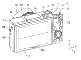
- FIG. 2 illustrates an external configuration of the imaging device 1 viewed from the rear.
- FIG. 3 is a front view showing the imaging device 1 shown in FIG.
- the imaging apparatus 1 is a small digital single-lens camera, and includes, for example, a main body 10, a viewfinder 20, and an imaging lens unit 30.
- the viewfinder 20 is capable of state transition between a storage state P1 (FIG. 3) stored in the main body 10 and a use state P3 (explained later) protruding (exposed) from the main body 10 to the outside.
- a storage state P1 FIG. 3
- P3 (explained later) protruding (exposed) from the main body 10 to the outside.
- the viewfinder 20 in the storage state P1 is indicated by a broken line
- the viewfinder 20 in the pop-up state P2 on the way from the storage state P1 to the use state P3 is indicated by a solid line.
- the viewfinder 20 will be described in detail later.
- the control unit 6 described later selects a mode for executing at least one of a power-on operation and a power-off operation in accordance with the state transition of the viewfinder 20.
- the lens side (subject side) is the front and the display unit side (image side) is the rear.
- the front-rear direction Z is the same as the optical axis direction of a lens (not shown) connected to the main body 10.
- the left-right direction of the main body 10 is defined as the X direction, and the left and right are expressed from the rear side of the main body 10 toward the front side.
- the vertical direction of the main body 10 is defined as the Y direction.
- the main body 10 has, for example, a rectangular parallelepiped shape, a body mount 11 is provided on the front surface 10A, and an image sensor 2A and an image signal processing unit 3 (both described later) and the like are accommodated therein.
- a display unit 12 is provided on the back surface 10 ⁇ / b> B of the main body 10.
- the body mount 11 performs mechanical or electrical connection between the main body 10 and the exchangeable imaging lens unit 30, and the user can select a lens according to the application and connect it to the main body 10.
- the imaging lens unit 30 includes a lens barrel 30B that houses one or more lenses 30A, and lens rings 30C and 30D provided around the lens barrel 30B.
- the lens rings 30C and 30D are mechanical keys for manually setting, for example, an aperture value, a shutter speed, a shooting mode, or a manual operation of focusing or zooming, and constitute a part of the input unit 8 (described later). To do.
- the number of lens rings is not particularly limited. It is not necessary to provide a lens ring.
- the imaging element 2A constitutes the imaging unit 2 (described later) together with the imaging lens unit 30 and the like, and forms an object image on the light receiving surface through the imaging lens unit 30, and generates an electrical signal by photoelectric conversion.
- a CCD Charge-Coupled Device
- CMOS Complementary Metal-Oxide Semiconductor
- the display unit 12 displays a through image during imaging obtained through the imaging lens unit 30, an image recorded on the storage medium 7 ⁇ / b> A (described later) in the main body 10, or various information such as a remaining battery level or imaging conditions. It is displayed on the surface 12A. Examples of shooting conditions include shutter speed, aperture value, f-number, level, or presence / absence of flash.
- the display unit 12 may have a touch panel unit (not shown), display an operation image such as a user interface image, and function as a touch panel.
- the display unit 12 includes, for example, a liquid crystal panel (LCD), an organic EL (Electro Luminescence) panel, and the like. As will be described in detail later, the display unit 12 may be rotatably connected to the main body 10.
- the control unit 6 starts or ends the display operation of the display unit 12 according to, for example, the state transition of the viewfinder 20.
- the viewfinder 20 is used for visually confirming a photographed image and performing composition setting, focusing, and the like.
- an optical viewfinder OVF: Optical View Finder
- an electronic viewfinder EMF: Electronic View Finder
- the viewfinder 20 has, for example, an eyepiece (not shown) and a liquid crystal panel in the back of the observation window 21 (not shown in FIGS. 1 to 3, see FIG. 7 described later).
- a display screen (not shown) such as an organic EL panel.
- the display screen in the viewfinder 20 displays various information such as the remaining battery level and shooting conditions (for example, shutter speed, aperture value, f-number, horizontality, presence / absence of flash) in addition to the through image being captured.
- the same display as that displayed on the display unit 12 may be displayed, or a different display may be displayed.
- the control unit 6 may display only a part of the plurality of information displayed on the display unit 12, for example. The control unit 6 may activate the display operation of the viewfinder 20 according to the state transition of the viewfinder 20, for example.
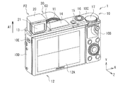
- FIGS. 4 to 7 The configuration of the viewfinder 20 will be further described with reference to FIGS. 4 to 7 in addition to FIGS. 4 is an external perspective view of the imaging device 1 in the pop-up state P2 with the viewfinder 20 protruding upward from the main body 10 when viewed from the front, and FIG. 5 is a view of the imaging device 1 in that state from the rear.
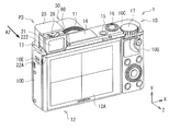
- FIG. 6 and 7 are perspective views when the viewfinder 20 in the use state P3 is viewed from the front or the rear.
- the viewfinder 20 can take three states: a storage state P1, a pop-up state P2, and a use state P3.
- the storage state P1 is a state in which the viewfinder 20 is stored in the main body 10, that is, a state in which the user (imager) does not use the viewfinder 20.
- the pop-up state P2 refers to a state in which the entire viewfinder 20 protrudes greatly from the main body 10 upward. In the pop-up state P2, more parts in the viewfinder 20 are exposed to the outside than the main body 10 as compared with the storage state P1.
- the use state P3 is an appropriate state for the user (imager) to use the viewfinder 20, and the movable unit 222 (described later) which is a part of the viewfinder 20 from the pop-up state P2 is the main body unit 221. This means the state that has advanced to the back of (see below).
- the viewfinder 20 is movable in two or more directions (vertical direction and front-rear direction) during the state transition between the housed state P1 and the use state P3 protruding out of the main body 10. Thereby, the whole structure of the imaging device 1 is reduced in size.
- the viewfinder 20 extends from the housed state P1 (see FIGS. 1 to 3) to the top of the main body 10 (in the direction of the arrow A1) as shown in FIGS. 4 and 5, for example, and reaches the pop-up state P2.
- the movable part 222 advances further to the back of the main body 10 (in the direction of the arrow A2) and reaches the use state P3.
- the viewing window 21 is positioned above the main body 10.
- the viewfinder 20 can be brought close to the configuration of a normal digital single-lens camera positioned above the lens barrel and the display unit 12, and the ease of use for the user can be improved. Further, by moving a part of the viewfinder 20 to the rear of the main body 10, it is possible to reduce the clearance to the eyes and improve the light shielding property.
- the eyepiece surface 22 ⁇ / b> A of the viewfinder 20 protrudes rearward from the back surface 10 ⁇ / b> B (display unit 12) of the main body 10.
- the clearance with the eye is reduced, the possibility that the user's nose hits the display unit 12 is reduced, and the usability is improved.
- the main body 10 preferably has an opening 13 on the upper surface 10 ⁇ / b> C through which the viewfinder 20 enters and exits the main body 10.
- an opening 21 through which the viewfinder 20 enters and exits the main body 10 other than the back surface 10B of the main body 10, and it becomes easy to cope with a larger diameter of the lens barrel and a larger screen of the display unit 12.
- the opening 13 is provided on the back surface 10B of the main body 10
- the lens barrel becomes smaller, thereby reducing the magnification and brightness. It is dark and the size of the image sensor is small. Further, the size of the display unit 12 is also reduced.
- the position of the opening 13 shown in FIGS. 1 to 3 is a place where a strobe is arranged in a normal digital single-lens camera, for example.
- the arrangement of the strobe 14 is changed and arranged at a position closer to the center than the opening 13.
- the viewfinder 20 is preferably provided at a position that does not overlap the body mount 11 as shown in FIG. 3 described above. Thereby, it is possible to avoid interference between the viewfinder 20 and the lens barrel. Note that the viewfinder 20 may overlap the display unit 12 in the rear view.
- FIG. 8 is a perspective view showing the appearance of the viewfinder 20 in the storage state P1 shown in FIGS.
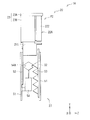
- FIG. 9 is a perspective view showing the appearance of the viewfinder 20 in the pop-up state P2 and the use state P3 shown in FIGS. 10A is a front view and a side view showing the configuration of the viewfinder unit 22 shown in FIG. 8 in the storage state P1 and the pop-up state P2.
- FIG. 10B is a side view showing the appearance of the viewfinder unit 22 shown in FIG. 8 in the usage state P3.
- the viewfinder 20 includes, for example, a viewfinder unit 22, a decorative member 23, a first movement mechanism 24, a second movement mechanism 25 (see FIGS. 10A and 10B), and a diopter adjustment unit 26 (FIG. 6, FIG. 6). 7 and 9).
- the viewfinder unit 22 is a portion exposed to the outside of the main body 10 in the pop-up state P2 and the use state P3.
- the main body portion 221 that extends upward with respect to the main body 10 and the rear portion with respect to the main body portion 221 And a movable part 222 extending to the right. It has the above-described viewing window 21 (see FIGS. 5 and 7), and an eyepiece and a display screen (both not shown) provided at the back of the viewing window 21.
- the decorative member 23 covers the side surface and the back surface of the viewfinder unit 22 other than the viewing window 21, and adjusts the appearance of the viewfinder 20 and the imaging device 1.
- the decorative member 23 includes, for example, an upper decorative member 23A and a side decorative member 23B.
- the upper face decorative member 23A constitutes a part of the exterior member of the upper face 10C of the main body 10 when the viewfinder 20 is in the housed state P1.
- the side decorative member 23B covers the side and back surfaces of the viewfinder unit 22 when the viewfinder 20 is in the pop-up state P2 and the use state P3.
- the side decorative member 23B preferably has a notch 23C that avoids the body mount 11. Thereby, as shown in FIG. 3, the viewfinder 20 can be arranged avoiding the body mount 11.
- the first moving mechanism 24 lifts the viewfinder unit 22 above the main body 10 and is constituted by, for example, a mechanical moving mechanism.
- the first moving mechanism 24 includes a base frame 31, a slide frame 32, a first elastic member 33, and a latching mechanism 34.
- the base frame 31 and the slide frame 32 have a double cylinder structure in which the slide frame 32 is inserted through the base frame 31.
- the base frame 31 includes, for example, a base frame main body 31A made of a metal plate or the like, a protruding portion 31B, a rotation restricting portion 31C, and a pressing portion 31D.
- the base frame main body 31A is fixed to the main body 10, for example.
- one end 33A of the first elastic member 33 is fixed to the base frame main body 31A.
- the base frame main body 31A is provided with a long hole 31E that defines the movement range of the other end 33B of the first elastic member 33.
- the protruding portion 31B is a portion that holds the latch mechanism 34, and is configured integrally with the rotation restricting portion 31C and the pressing portion 31D.
- the rotation restricting portion 31 ⁇ / b> C restricts the rotation range of the latching mechanism 34 and is provided in the guide groove 34 ⁇ / b> B of the latching mechanism 34.
- the holding portion 31D is configured to prevent the collar portion 34C of the latching mechanism 34 from falling off from the hole 32B of the slide frame 32.
- the slide frame 32 has a slide frame main body 32A made of, for example, a metal plate and a hole 32B.
- the slide frame main body 32A is fixed to a decorative member 23 that covers the viewfinder unit 22 by screws 32C (see FIG. 9).
- the hole 32 ⁇ / b> B holds the viewfinder 20 in the housed state P ⁇ b> 1 by receiving the collar portion 34 ⁇ / b> C of the latching mechanism 34.
- the first elastic member 33 is provided between the base frame 31 and the slide frame 32 and biases the slide frame 32 upward.
- the first elastic member 33 is preferably constituted by a spring, for example.
- the kind of spring is not specifically limited, For example, it is preferable that it is comprised by the tension coil spring or the torsion coil spring.
- One end 33A of the first elastic member 33 is fixed to the base frame main body 31A of the base frame 31, and the other end 33B of the first elastic member 33 is fixed to the slide frame main body 32A of the slide frame 32.
- the latching mechanism 34 restricts the upward movement of the slide frame 32, and includes, for example, an attachment portion 34A, a guide groove 34B, a flange portion 34C, and a receiving portion 34D.
- the attachment portion 34A is rotatably attached to the protruding portion 31B of the base frame 31.
- the guide groove 34 ⁇ / b> B defines a rotation range of the latch mechanism 34.
- a rotation restricting portion 31C for the base frame 31 is provided in the guide groove 34B.
- the collar portion 34C is extended downward from one place of the attachment portion 34A.
- the receiving portion 34D is a portion that holds a viewfinder operation portion (button) 10E provided on the side surface 10D of the main body 10.
- the viewfinder operating portion 10E is held by the receiving portion 34D, whereby the rotation of the attachment portion 34A is restricted, and the state where the collar portion 34C is hooked in the hole 32B of the slide frame 32 is maintained.
- the viewfinder operation section 10E is detached from the receiving section 34D, whereby the attachment section 34A is rotated and the collar section 34C is detached from the hole 32B of the slide frame 32. It is like that.
- the second moving mechanism 25 moves the movable part 222 of the viewfinder unit 22 to the rear of the main body 10, and is constituted by, for example, a mechanical moving mechanism.
- the second moving mechanism 25 has a second elastic member 41 as shown in FIGS. 10 and 11.
- the second elastic member 41 is provided between the viewfinder unit 22 and the decorative member 23, and biases the viewfinder unit 22 rearward (Z direction).
- the second elastic member 41 is preferably constituted by a spring, for example.
- the kind of spring is not specifically limited, For example, it is preferable that it is comprised by the unusual shaped compression spring.
- One end 41 ⁇ / b> A of the second elastic member 41 is fixed to the back surface of the viewfinder unit 22, and the other end 41 ⁇ / b> B of the second elastic member 41 is fixed to the decorative member 23.
- the viewfinder unit 22 is preferably held by the back surface 10 ⁇ / b> B of the main body 10, and movement by the urging force of the second elastic member 41 is preferably suppressed.
- the second moving mechanism 25, that is, the second elastic member 41 can be omitted, and the user can pull out the movable portion 222 of the viewfinder unit 22 backward by hand.
- the operation of extending the viewfinder 20 above the main body 10 is performed using the first moving mechanism 24 that is a mechanical moving mechanism.
- the electric movement mechanism 27 instead of the first movement mechanism 24 as in the imaging apparatus 1A as a modification example shown in FIGS. 11A and 11B.
- the imaging apparatus 1A includes, for example, a viewfinder unit 22 and an electric movement mechanism 27.
- the electrical movement mechanism 27 is for lifting the viewfinder unit 22 above the main body 10 and includes, for example, a base frame 51, a slide frame 52, a rack 53, and a motor 54.
- the base frame 51 and the slide frame 52 have a double cylinder structure in which the slide frame 52 is inserted through the base frame 51.
- the inside of the base frame 51 and the slide frame 52 is hollow, and the battery of the strobe 14 can be accommodated.
- the rack 53 is provided on the slide frame 52.
- the motor 54 has a worm gear 54 ⁇ / b> A that is fixed to the base frame 51 and meshes with the rack 53.
- the viewfinder 20 When not in use, the viewfinder 20 is in the storage state P1 in the main body 10 (see FIGS. 1 to 3).
- the motor 54 is rotated by the user operating a viewfinder operation unit (not shown) provided in the main body 10. Since the worm gear 54A attached to the rotating shaft of the motor 54 and the rack 53 are engaged with each other, the rack 53 slides (see FIG. 11B). As a result, the slide frame 52 moves above the main body 10 and the viewfinder unit 22 pops up outside the main body 10 (see FIGS. 4 and 5). The raised slide frame 52 and viewfinder unit 22 are held in the popped-up position by the self-locking of the worm gear 54A, and the pop-up state P2 is maintained.
- the backward movement of the movable portion 222 due to the urging force of the second elastic member 41 is suppressed by the back surface 10B of the exterior member of the main body 10 (see FIG. 11A).
- the viewfinder unit 22 advances to the outside of the main body 10
- the movable portion 222 advances to the rear of the main body 10 due to the urging force of the second elastic member 41 and reaches the use state P3 (see FIG. 11B).
- the viewfinder 20 can shift the state from the storage state P1 to the use state P3 fully automatically.
- the diopter adjustment unit 26 is an operation unit (lever, knob, dial, etc.) for adjusting the power of the viewfinder 20 according to the eyesight of the user.
- the diopter adjustment unit 26 is provided on the upper surface of the viewfinder unit 22 of the viewfinder 20, for example. Further, the diopter adjustment unit 26 is covered with the upper decorative member 23A of the decorative member 23 in the housed state P1 and the pop-up state P2 (see FIGS. 1 to 3). On the other hand, in the use state P3, it is exposed to the outside from the upper face decorative member 23A of the decorative member 23 and can be operated (see FIGS. 6 and 7). By limiting access to the diopter adjustment unit 26 in this way, it is possible to avoid unintentionally operating the diopter adjustment unit 26 and changing settings.
- the diopter adjustment unit 26 is not limited to a mechanical operation unit, and may be an electronic operation unit.
- diopter adjustment data corresponding to the user may be stored in a storage unit (not shown) inside the control unit 6. Such storage of diopter adjustment data may be performed, for example, by pressing the release button 16 (described later) during a photographing operation.
- the display unit 12 is provided so as to be rotatable with respect to the main body 10, and the display surface 12A can be directed forward (see FIG. 12).
- the state shown in FIG. 12 corresponds to a self-shooting mode in which the user takes an image of the user himself as a subject.
- a power button 15, a release button 16, and a mode setting dial 17 that constitute a part of the input unit 8 are further provided on the upper surface 10 ⁇ / b> C of the main body 10.
- the power button 15 is for performing the power-on operation and the power-off operation of the entire imaging apparatus 1.
- the release button 16 is for performing a photographing operation, and is, for example, a two-stage detection button that can detect two states of a half-pressed state and a fully-pressed state. When the release button 16 is pressed halfway, a preparatory operation for acquiring a recording image (main photographed image) related to the subject is performed.
- the preparatory operation here is, for example, an AF (Automatic Focus) control operation, an AE (Automatic Exposure) control operation, or the like.
- the photographing operation is a series of operations for performing an exposure operation on a subject image using the image sensor 2A and performing predetermined image processing on an image signal obtained by the exposure operation.
- the mode setting dial 17 is used to set various operation modes of the imaging apparatus 1. Examples of the operation mode of the imaging apparatus 1 include a shooting mode, a playback mode for playing back a captured image, and a communication mode for performing data communication with an external device.
- the imaging device 1 may include an eye sensor 60 in the vicinity of the viewfinder 20 on the back surface 10B of the main body 10, for example.
- the eye sensor 60 detects, for example, whether or not the user (imager) is looking through the viewfinder 20 by using a magnetic sensor, and switches between display by the display unit 12 and display by the viewfinder 20. For example, when the eye sensor 60 detects the approach of the user's eyes, no image is displayed on the display surface 12 ⁇ / b> A of the display unit 12. If the image is displayed on the display surface 12A, the image light from the display surface 12A is incident on the user's eye looking into the viewing window 21 of the viewfinder 20, and the display screen inside the viewfinder 20 is displayed. This is because it hinders visual recognition.
- the imaging apparatus 1 may include an eye sensor 60A in the vicinity of the viewing window 21 in the viewfinder 20 at the use position P3 as shown in FIGS. 13A and 13B, for example, instead of the eye sensor 60.
- FIG. 13A is an enlarged perspective view showing the vicinity of the viewing window 21 of the imaging apparatus 1, and FIG. 13B shows a cross-sectional configuration of the eye sensor 60A.
- the eye sensor 60A includes, for example, a sensor window 61, a sensor device 62, and a reflecting member 63.
- the sensor device 62 is installed perpendicular to the sensor window 61.
- the reflection member 63 is provided in the optical path LP between the sensor window 61 and the sensor device 62. Thereby, size reduction of the imaging device 1 is possible.
- the sensor window 61 is provided, for example, on the eyepiece 22A of the viewfinder 20 (for example, a region around the viewing window 21, for example, lower left in FIG. 13A).
- the eye sensor 60A in the viewfinder 20 in this way, it is possible to install the eye sensor 60A at a position close to the eye and improve detection accuracy. Further, in the storage state P1, the eye sensor 60A is hidden in the main body 10, and the risk of erroneous operation is reduced.
- the sensor device 62 has, for example, a light receiving element 62B on a substrate 62A and is mounted on a support member 64.
- the light receiving element 62 ⁇ / b> B detects a change in the amount of incident light transmitted through the sensor window 61, thereby detecting whether or not the user's eyes are approaching.
- the reflecting member 63 has a reflecting surface 63A that reflects light on a mirror surface, and thereby changes the path of light.
- the reflection member 63 may be provided as a member integral with the sensor window 61 as illustrated in FIG. 13B, or may be provided as a member different from the sensor window 61.
- FIG. 14 is a block diagram showing the overall configuration of the imaging apparatus 1.
- the imaging device 1 includes an imaging unit 2, an image signal processing unit 3, an encoding / decoding unit 4, an image memory 5, a control unit 6, a speaker 6A, a motor 6B, and a recording / reproducing unit 7. And an input unit 8 and detection units 9A and 9B.
- the imaging lens unit 30 is included in the imaging unit 2.
- the imaging unit 2 is a mechanism for acquiring captured image data.
- the imaging unit 2 includes, for example, an imaging element 2A, a preprocessing unit 2B, a timing generator 2C, and a driving unit 2D.
- the image sensor 2A is driven based on the timing signal output from the timing generator 2C, photoelectrically converts incident light from the subject, converts it into a charge amount, and outputs it as an analog image signal.
- the analog imaging signal output from the imaging element 2A is output to the preprocessing unit 2B.
- the pre-processing unit 2B includes a sample hold / AGC (Automatic Gain Control) circuit, a video A / D converter, and the like that perform gain adjustment and waveform shaping on the analog image pickup signal obtained by the image pickup device 2A.
- the timing generator 2 ⁇ / b> C outputs a timing signal to the image sensor 2 ⁇ / b> A according to a command from the control unit 6.
- the drive unit 2D performs focusing, zooming, shutter speed adjustment, aperture adjustment, and the like in the imaging lens unit 30 based on control by the control unit 6.
- the image signal processing unit 3 performs various types of image signal processing, such as gradation correction processing, shading correction processing, high-frequency correction (contour correction) processing, or camera shake correction processing, on the captured image data obtained by the imaging unit 2. Is to be applied.
- the encode / decode unit 4 performs compression processing on the captured image data that has been subjected to image signal processing by the image signal processing unit 3, and decompression processing on the compressed captured image data.
- compression processing and decompression processing in a predetermined still image format such as JPEG (JointoPhotographic Experts Group) format are performed.
- JPEG Joint Photographic Experts Group
- MPEG Motion Picture Experts Group
- the image memory 5 is a volatile memory, for example, a buffer memory composed of DRAM (Dynamic Random Access Memory), and is subjected to predetermined processing by the preprocessing unit 2B, the image signal processing unit 3, and the encoding / decoding unit 4.
- the stored image data is temporarily stored.
- the control unit 6 includes, for example, a CPU (Central Processing Unit), a RAM (Random Access Memory), a ROM (Read-Only Memory), and the like.
- the ROM stores a program that is read and operated by the CPU.
- the RAM is used as a work memory for the CPU.
- the CPU controls the entire imaging apparatus 1 by executing various processes in accordance with programs stored in the ROM and issuing commands.
- the recording / reproducing unit 7 includes a semiconductor memory such as a flash memory, or a recording medium 7A such as a magnetic disk, an optical disk, and a magneto-optical disk, and a media drive 7B. Based on the control by the control unit 6, the media drive 7B records the still image format or moving image format compressed photographed image data obtained by the encoding / decoding unit 4 on the recording medium 7A and the recording medium 7A. Various data of the compressed photographed image data is reproduced (read).
- a semiconductor memory such as a flash memory
- a recording medium 7A such as a magnetic disk, an optical disk, and a magneto-optical disk
- a media drive 7B Based on the control by the control unit 6, the media drive 7B records the still image format or moving image format compressed photographed image data obtained by the encoding / decoding unit 4 on the recording medium 7A and the recording medium 7A. Various data of the compressed photographed image data is reproduced (read).
- the input unit 8 is a part where a user performs various operation inputs to the imaging device 1.
- a touch panel unit included in the display unit 12 a power button 15 provided on the main body 10, a release button 16 and a mode setting dial 17,
- lens rings 30 ⁇ / b> C and 30 ⁇ / b> D provided in the imaging lens unit 30.
- the input unit 8 detects a user's input operation and transmits information (operation input information) corresponding to the input operation to the control unit 6.
- the detection unit 9A has a sensor for detecting the rotation of the display unit 12. Whether the display unit 12 is in the normal photographing state shown in FIGS. 1 to 7 or in the inverted state shown in FIG. Is detected. In other words, the detection unit 9A includes either the first rotation state (the normal photographing state where the display surface 12A faces rearward) or the second rotation state (the inverted state where the display surface 12A faces frontward). It is what detects whether it is. On the other hand, the detection unit 9B detects which state the viewfinder 20 is in between the storage state P1 and the use state P3. Sensors using a mechanical method, an electromagnetic method, or an optical method are applied as the detection units 9A and 9B. When the detection unit 9A detects that the display unit 12 is in the self-portrait state (in the reverse position), the control unit 6 selects a mode in which the operation of the eye sensor 60 is stopped.
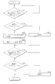
- FIG. 15 is a first flowchart showing a flow of a series of operations from starting to stopping of the imaging apparatus 1.
- the control unit 6 can select a mode for executing at least one of a power-on operation and a power-off operation in accordance with the state transition of the viewfinder 20. For example, the control unit 6 performs a power-on operation when the viewfinder 20 shifts from the storage state P1 to the use state P3, or when the viewfinder 20 shifts from the use state P3 to the storage state P1. Turn off the power.
- the processing shown in FIG. 15 is executed by the control unit 6 according to a program stored in, for example, a ROM.
- the viewfinder 20 When not in use, the viewfinder 20 is in the storage state P1 of the main body 10 (see FIGS. 1 to 3). At this time, since the viewfinder operation unit 10E is held by the receiving portion 34D of the latching mechanism 34, the rotation of the mounting portion 34A of the latching mechanism 34 is restricted, and the flange 34C of the latching mechanism 34 slides. The state of being engaged with the hole 32B of the frame 32 is maintained (see FIG. 8).
- the viewfinder 20 starts a pop-up operation that is a state transition from the housed state P1 housed in the main body 10 to the pop-up state P2. That is, the viewfinder operation unit 10E is slid to pop up the viewfinder unit 22 from the main body 10. More specifically, by sliding the viewfinder operation section 10E, the viewfinder operation section 10E is detached from the receiving section 34D of the latch mechanism 34, and the attachment section 34A of the latch mechanism 34 is rotated. Thereby, the collar part 34C of the latching mechanism 34 escapes from the hole 32B of the slide frame 32 (refer FIG. 9).
- the detection unit 9B determines whether or not the state transition from the storage state P1 to the pop-up state P2 is started, that is, whether or not the viewfinder 20 starts to move from the storage state P1 to the pop-up state P2 (step S101). ). When the start of the state transition from the storage state P1 to the pop-up state P2 is detected, it is determined whether or not the power is turned on (step S102). When the start of the state transition from the storage state P1 to the pop-up state P2 is not detected, step S101 is performed again.
- step S102 when it is determined that the power is already turned on by the power button 15, the display screen of the viewfinder 20 is activated (step S103), and predetermined information and a through image are displayed. At this time, the viewfinder 20 is also shifted from the pop-up state P2 to the use state P3.
- the movable part 222 of the viewfinder unit 22 may be advanced to the rear of the main body 10, or the movable part 222 may be pulled out by hand. That is, using both the first moving mechanism 24 and the second moving mechanism 25, the state transition from the storage state P1 to the use state P3 may be performed automatically, or the second moving mechanism 25 is used. You may make it carry out one part manually.
- step S104 the power is turned on (step S104), and the process of step S103 is further performed.
- the control unit 6 may execute the display operation of only the display unit 12 when the viewfinder 20 is in the storage state P1 or the pop-up state P2.
- the display operation of both the display unit 12 and the display screen of the viewfinder 20 may be executed. Good.
- the control unit 6 may display the display screen of the viewfinder 20, for example, only a part of the plurality of pieces of information displayed on the display unit 12 may be displayed by the control unit 6.
- the control unit 6 selects a shooting mode or commands execution of the shooting mode (step S105).
- the shooting modes are roughly classified into, for example, a self-shooting mode and a normal shooting mode, and have a still image shooting mode and a moving image shooting mode, respectively.
- the state shift from the pop-up state P2 to the storage state P1 is started. That is, after the movable part 222 of the viewfinder unit 22 is pushed forward so as to be hidden by the decorative member 23, the viewfinder unit 22 and the decorative member 23 are pushed downward to be housed inside the main body 10.
- the control unit 6 may terminate functions such as the display operation of the viewfinder 20.
- the detection unit 9B determines, for example, whether or not the state transition from the pop-up state P2 to the storage state P1 is started, that is, whether or not the viewfinder 20 starts to move from the pop-up state P2 to the storage state P1 ( Step S106).
- Step S107 it is determined whether or not the power is turned off (step S107). If the start of the state transition from the pop-up state P2 to the storage state P1 is not detected, step S106 is performed again.
- step S107 when it is determined that the power has already been turned off by the power button 15, the series of operations ends.
- the series of operations is completed by turning off the power (step S108).
- the control unit 6 changes the state of the viewfinder 20 from the use state P3 to the storage state P1, and then continues the shooting mode without turning off the power, or shifts to the power saving mode (sleep mode). It may be.
- the control unit 6 turns on the power using the transition start from the storage state P1 to the pop-up state P2 as a trigger, and turns off the power using the start of transition from the pop-up state P2 to the storage state P1.
- the power may be turned on using the following detection of ⁇ 1> to ⁇ 3> as a trigger.
- ⁇ 1> The transition from the storage state P1 to the pop-up state P2 is completed. That is, the viewfinder 20 has moved from the storage state P1 and has reached the pop-up state P2.
- the movable part 222 of the viewfinder unit 22 starts to move rearward of the main body part 221.
- the transition from the pop-up state P2 to the use state P3 is completed. That is, the viewfinder 20 has reached the use state P3 when the movable part 222 of the viewfinder unit 22 completes the rearward movement of the main body part 221.
- the power-off may be performed with the detection of any one of ⁇ 4> to ⁇ 6> below as a trigger.
- the transition from the pop-up state P2 to the storage state P1 is completed. That is, the viewfinder 20 has moved from the pop-up state P2 and has reached the storage state P1.
- the viewfinder 20 can be moved in two or more directions between the housed state P1 housed in the main body 10 and the use state P3 projecting out of the main body 10. Accordingly, the opening 13 through which the viewfinder 20 enters and exits the main body 10 can be provided in addition to the back surface 10B of the main body 10, and the main body 10 can be reduced in size while corresponding to the increase in the diameter of the lens barrel and the increase in the screen of the display section 12. Can be realized.
- the control unit 6 may perform various output operations in accordance with the state transition of the movable unit 222 in the viewfinder unit 22.
- the imaging device 1 may operate as shown in FIGS. 16A and 16B, for example.
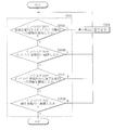
- FIG. 16A is a second flowchart showing a flow of a series of operations from starting to stopping of the imaging apparatus 1.
- FIG. 16B is a flowchart showing a part of the process (step S203) of FIG. 16A in more detail.
- the control unit 6 can select a mode in which various output operations are performed according to the state transition of the movable unit 222 of the viewfinder unit 22.
- the various output operations referred to here are, for example, warning display, generation of warning sound, or warning vibration. Since points other than the above are substantially the same as those of the first embodiment, description thereof will be omitted. 16A and 16B is also executed by the control unit 6 according to a program stored in, for example, a ROM.
- the power is turned on by pressing the power button 15 (step S201).
- the power may be turned on according to the state transition between the storage state P1 and the use state P3 of the viewfinder 20.
- the control unit 6 can turn on the power at an arbitrary timing from the storage state P1 to the use state P3.
- the display screen of the viewfinder 20 is activated and predetermined information and a through image are displayed (step S202). At this time, the display operation of the display unit 12 may be started together.
- the display screen of the viewfinder 20 various information such as the remaining battery level and shooting conditions (for example, shutter speed, aperture value, f-number, horizontality, presence / absence of flash) are displayed in addition to the through image being captured. You may make it display much more information on the display part 12.
- the display unit 12 may display only information using characters, figures, symbols, or the like without displaying the through image being captured. Further, on the display screen of the viewfinder 20, for example, only some information of a plurality of information displayed on the display unit 12 may be displayed.
- step S203 it is determined whether or not the viewfinder 20 is in the use state P3 (step S203).
- the movable part 222 moves backward from the main body part 221, that is, when the pulling-out operation is not started, or the movable part 222 starts moving backward from the main body part 221.
- the position of the drawn movable part 222 is not appropriate.
- the viewfinder 20 in the middle of the pop-up operation, for example, when the viewfinder 20 is caught on the inner surface of the opening 13 and stops moving upward, or the movable part 222 pulled out from the main body 221 moves in the middle due to mechanical friction or the like. For example. In these cases, the image on the display screen provided in the viewfinder 20 is blurred even if the user can look into the viewing window 21.
- step S203 specifically, the processing from step S203A to step S203D shown in FIG. 16B is performed.
- step S203A it is determined whether or not the viewfinder 20 has started the movement from the stored state P1 to the pop-up state P2, that is, the pop-up operation. If it is determined in step S203A that the pop-up operation has started, it is determined whether or not the viewfinder 20 has reached the pop-up state P2 (step S203B). On the other hand, if it is determined in step S203A that the pop-up operation has not started, it is considered that the user has forgotten the operation of the viewfinder operation unit 10E, for example.
- the viewfinder operation unit 10E is appropriately operated, it is considered that the viewfinder 20 is not moved due to some mechanical trouble.
- a warning is displayed on the display unit 12 (step S204), and the process returns to step S203A again.
- step S203B If it is determined in step S203B that the viewfinder 20 has reached the pop-up state P2, it is further determined whether or not the viewfinder 20 has started moving from the pop-up state P2 to the use state P3 (step S203C). On the other hand, if it is determined in step S203B that the viewfinder 20 has not reached the pop-up state P2, for example, the user has appropriately operated the viewfinder operation unit 10E, but the viewfinder 20 has some mechanical trouble. Is not popping up to the proper position. Since the viewfinder 20 cannot be used as it is, the display unit 12 also displays a warning to that effect (step S204) and returns to step S203A (or step S203B) again.
- step S203C When it is determined in step S203C that the viewfinder 20 has started moving from the pop-up state P2 to the use state P3, it is determined whether or not the viewfinder 20 has reached the use state P3 (step S203D). On the other hand, if it is determined in step S203C that the viewfinder 20 has not started moving from the pop-up state P2 to the use state P3, for example, the user has forgotten to perform the pull-out operation of the movable portion 222. Conceivable. If this is the case, the display screen inside the viewfinder 20 will be visually perceived in a blurred manner. In this case as well, for example, a warning is displayed on the display unit 12 (step S204), and step S203A (or step S203C) is performed again. Return to.
- step S203D If it is determined in step S203D that the viewfinder 20 has reached the use state P3, step S203 is completed. On the other hand, if it is determined in step S203D that the viewfinder 20 is not in the use state P3, for example, it is considered that the user has started the pulling operation of the movable portion 222 but has not performed the pulling operation to an appropriate position. If this is the case, the display screen inside the viewfinder 20 will be visually perceived in a blurred manner. In such a case as well, a warning is displayed on the display unit 12 (step S204), and again in step S203A (or step S203D). Return.
- step S204 in addition to the warning display on the display unit 12, or together with the warning display on the display unit 12, a warning sound is generated on the speaker 6A (FIG. 14) provided on the main body 10 or provided on the main body 10.
- a warning vibration may be caused in the motor 6B (FIG. 14).
- at least one of the generation of the warning sound and the warning vibration may be executed without performing the warning display on the display unit 12.
- step S203 the control unit 6 selects an operation mode or instructs execution of the operation mode (step S205).
- the shooting mode include a still image capturing mode and a moving image capturing mode.
- the state of the viewfinder 20 is changed from the use state P3 to the storage state P1 stored in the main body 10 via the pop-up state P2 (step S206). That is, after the viewfinder unit 22 is pushed forward and hidden behind the decorative member 23, the viewfinder unit 22 and the decorative member 23 are pushed downward to be housed inside the main body 10.
- the control unit 6 may terminate functions such as the display operation of the viewfinder 20.
- control unit 6 determines whether or not the power is turned off (step S207). When it is determined that the power is already turned off by operating the power button 15, the series of operations is finished as it is. . When it is determined that the power is not turned off, the power supply is turned off to complete a series of operations (step S208).
- the control unit 6 changes the state of the viewfinder 20 from the use state P3 to the storage state P1, and then continues the shooting mode without turning off the power, or shifts to the power saving mode (sleep mode). You may do it.
- various output operations are executed by the control unit 6 in accordance with the state transition of the viewfinder 20. Therefore, the user can instantly recognize whether or not the viewfinder 20 is in an appropriate usage state. Therefore, according to the present embodiment, operability is improved and smooth shooting by the user is possible.
- the power is turned on by pressing the power button 15 or the like (step S201).
- the viewfinder 20 is changed from the housed state P1 to the used state.
- the power may be turned on at the time of shifting to P3.
- step S202 and step S203 may be interchanged, for example, as in a flowchart as a modified example illustrated in FIG. 16C. That is, after the power is turned on (step S201), it is possible to activate the display screen of the viewfinder 20 after confirming that the viewfinder 20 is in the use state P3 (step S203) (step S202).
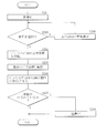
- the control unit 6 may start and stop the eye sensor 60 in accordance with the state transition of the viewfinder 20. Specifically, the imaging device 1 may operate as shown in FIGS. 17A and 17B, for example. 17A and 17B are third flowcharts showing a flow of a series of operations from starting to stopping of the imaging apparatus 1. Since points other than the above are substantially the same as those of the first embodiment, description thereof will be omitted. Note that the control unit 6 also executes the processing illustrated in FIGS. 17A and 17B according to a program stored in, for example, a ROM.
- control unit 6 selects a mode for executing at least one of turning on and off the eye sensor 60 in accordance with the state transition of the viewfinder unit 22. Further, the control unit 6 may change the assignment of the functions of the plurality of mechanical keys depending on whether the eye sensor 60 detects that the viewfinder 20 is used by the user or not. The case where the eye sensor 60 detects that the viewfinder 20 is being used by the user is a case where it is detected that the user's eyes have approached the viewing window 21 of the viewfinder 20. .
- the change in the function assignment of the plurality of mechanical keys is, for example, whether or not the function of the lens rings 30C and 30D provided around the lens barrel 30B is looking through the viewing window 21 of the viewfinder 20. It means changing.
- the lens ring 30C functions as an operation unit for setting the shutter speed, and when the user is looking through the viewing window 21, the lens ring 30C is used.
- the ring 30C may function as an operation unit that performs focusing.
- the mode of assigning the functions of the plurality of mechanical keys is not limited to this.
- the viewfinder 20 starts to shift from the housed state P1 housed in the main body 10 to the pop-up state P2. That is, the viewfinder operation unit 10E is slid to pop up the viewfinder unit 22 from the main body 10.
- the detection unit 9B determines whether or not the state transition from the storage state P1 to the pop-up state P2 is started, that is, whether or not the viewfinder 20 starts to move from the storage state P1 to the pop-up state P2 (step S301).
- the start of the state transition from the storage state P1 to the pop-up state P2 is detected, it is determined whether or not the power is turned on (step S302). If the start of the state transition from the storage state P1 to the pop-up state P2 is not detected, step S301 is performed again.
- step S302 If it is determined in step S302 that the power is already turned on by the power button 15, the display screen of the viewfinder 20 is activated (step S303), and predetermined information and a through image are displayed. At this time, the viewfinder 20 is also shifted from the pop-up state P2 to the use state P3. If it is determined in step S302 that the power is not turned on, the power is turned on (step S304), and the process of step S303 is further performed. Note that when the power is turned on by the power button 15, the control unit 6 may execute the display operation of only the display unit 12 when the viewfinder 20 is not in the use state P3.
- the power may be automatically turned on (at any timing from the storage state P1 to the use state P3). Further, on the display screen of the viewfinder 20, for example, only some information of a plurality of information displayed on the display unit 12 may be displayed.
- the control unit 6 determines whether or not the user is looking through the viewing window 21 by using the eye sensor 60 (step S306). If it is determined that the user is looking through the viewing window 21, the display on the display surface 12A of the display unit 12 is turned off (step S307). After that, the photographing mode is selected or execution of the photographing mode is instructed (step S308). Next, the display unit 12 is in the first rotation state (normal photographing state) shown in FIGS. 1 to 7 or the second rotation state (reverse state) shown in FIG. 12 by the detection unit 9A. Is detected (step S309).
- the control unit 6 turns off the eye sensor 60 (step S310).
- the approach of the display unit 12 is mistaken as the approach of the user's eyes, and the display surface 12A of the display unit 12 is turned off.
- a user taking a self-portrait cannot view a through image to be displayed on the display surface 12A.
- the state shift from the pop-up state P2 to the storage state P1 is started. That is, after the movable part 222 of the viewfinder unit 22 is pushed forward so as to be hidden by the decorative member 23, the viewfinder unit 22 and the decorative member 23 are pushed downward to be housed inside the main body 10.
- the control unit 6 may terminate functions such as the display operation of the viewfinder 20.
- the detection unit 9B determines, for example, whether or not the state transition from the pop-up state P2 to the storage state P1 is started, that is, whether or not the viewfinder 20 starts to move from the pop-up state P2 to the storage state P1 ( Step S311).
- Step S311 When the start of the state transition from the pop-up state P2 to the storage state P1 is detected, it is determined whether or not the love sensor is turned on (step S312). If the start of the state transition from the pop-up state P2 to the storage state P1 is not detected, step S311 is performed again.
- step S312 If it is determined in step S312 that the eye sensor 60 is on, the eye sensor 60 is turned off (step S313). Finally, it is determined whether or not the power is turned off (step S314). When it is determined that the power has already been turned off by operating the power button 15, the series of operations ends as it is. If it is determined that the power is not turned off, the power supply is turned off to end the series of operations (step S315). Note that the control unit 6 changes the state of the viewfinder 20 from the pop-up state P2 to the storage state P1. After the image sensor is turned off or after the eye sensor 60 is turned off, the photographing mode may be continued without turning off the power, or the mode may be shifted to the power saving mode (sleep mode).
- control unit 6 may execute the display operation of only the display unit 12 when the viewfinder 20 is not in the use state P ⁇ b> 3.
- the control unit 6 may execute the display operation of both the display unit 12 and the viewfinder 20 when the power button 15 is turned on.
- control unit 6 performs the on / off processing of the eye sensor 60 in accordance with the state transition of the viewfinder 20. For this reason, the user does not need to perform the on / off operation of the eye sensor 60 as an operation different from the operation of changing the state of the viewfinder 20. Therefore, according to the present embodiment, operability is improved and smooth shooting by the user is possible.
- the control unit 6 is configured to turn on the power, start up the display screen of the viewfinder 20, and turn on the eye sensor 60, triggered by the start of the transition from the storage state P1 to the pop-up state P2.
- the eye sensor 60 is turned off and the power is turned off using the start of the transition from the pop-up state P2 to the storage state P1 as a trigger.
- the present technology may be configured as follows. For example, the power-on, the activation of the display screen of the viewfinder 20, and the turning on of the eye sensor 60 may be performed using the following detections ⁇ 1> to ⁇ 3> as triggers. ⁇ 1> The transition from the storage state P1 to the pop-up state P2 is completed.
- the viewfinder 20 has moved from the storage state P1 and has reached the pop-up state P2.
- the transition from the pop-up state P2 to the use state P3 is completed. That is, the viewfinder 20 has reached the use state P3 when the movable part 222 of the viewfinder unit 22 completes the rearward movement of the main body part 221.
- the eye sensor 60 may be turned off and the power may be turned off using the following detection of ⁇ 4> to ⁇ 6> as a trigger.
- ⁇ 4> The transition from the pop-up state P2 to the storage state P1 is completed. That is, the viewfinder 20 has moved from the pop-up state P2 and has reached the storage state P1.
- ⁇ 5> Start of transition from the use state P3 to the pop-up state P2. That is, the movable part 222 of the viewfinder unit 22 starts to move forward toward the main body part 221.
- ⁇ 6> The transition from the use state P3 to the pop-up state P2 is completed. That is, the viewfinder 20 has reached the pop-up state P2 when the movable part 222 of the viewfinder unit 22 completes the forward movement toward the main body part 221.
- the present disclosure has been described with reference to the embodiment, the present disclosure is not limited to the above-described embodiment, and various modifications can be made.
- the configurations of the first moving mechanism 24, the second moving mechanism 25, and the electric moving mechanism 27 are not limited to the examples described in the above embodiment, and may have other configurations.
- the viewfinder 20 is movable in the two directions above and behind the main body 10 .
- the viewfinder 20 can be made movable not only in two directions but also in three or more directions.
- the moving direction and path of the viewfinder 20 are not particularly limited.
- the viewfinder 20 moves backward (Z direction). It is also possible to do.
- the said embodiment demonstrated the case where the image imaged with the main body 10 was displayed on the display part 12 attached to the main body 10, it replaces with the display part 12 and is a smart phone (multifunctional mobile phone). It is also possible to use a display or a monitor of a personal computer.
- shape, dimensions, and materials of each component described in the above embodiment are not limited, and other shapes, dimensions, and materials may be used.
- the configuration of the imaging apparatus 1 has been specifically described. However, it is not necessary to include all the components, and other components may be further included.
- a main body provided with an imaging unit;
- a viewfinder capable of state transition between a storage state stored in the main body and a use state protruding from the main body;
- An imaging apparatus comprising: a control unit that turns on or off according to the state transition.
- the imaging device according to (1) wherein the control unit performs power-on when the storage state is shifted to the use state.
- the viewfinder moves in two or more directions during the state transition.
- the imaging apparatus is any one of (1) to (3).
- the viewfinder is A main body part and a movable part movable relative to the main body part; After shifting from the stored state to the pop-up state in which the main body portion protrudes upward from the main body, the movable portion moves from the pop-up state to the rear of the main body portion to shift to the use state.
- the imaging unit (6)
- the control unit performs power-on when shifting from the stored state to the pop-up state.
- the imaging device according to (6), wherein the control unit turns on the power when the transition from the stored state to the pop-up state starts or when the transition is completed.
- the imaging device as described in any one of said (1) to (11).
- the viewfinder is an electronic viewfinder, The imaging device according to (12), wherein the control unit causes the display unit to display a plurality of pieces of information and causes the electronic viewfinder to display a part of the pieces of information.
- the viewfinder is an electronic viewfinder, The imaging device according to any one of (1) to (13), wherein the control unit activates the operation of the electronic viewfinder when the storage state is shifted to the use state.
- the viewfinder is an electronic viewfinder, The imaging device according to any one of (1) to (14), wherein the control unit stops the operation of the electronic viewfinder when the use state is shifted to the housed state.
- the viewfinder is an electronic viewfinder, When the power is turned on by the power button, the control unit causes the display unit to execute a display operation when the electronic viewfinder is in the retracted state, and the electronic viewfinder is in the use state.
- the imaging apparatus according to (1), wherein the display operation is performed by both the display unit and the electronic viewfinder.
- a storage unit includes a main body part, a movable part movable with respect to the main body part, and a diopter adjustment part that performs diopter adjustment according to a user,
- the imaging unit according to any one of (1) to (16), wherein the storage unit stores diopter adjustment data according to the user by the diopter adjustment unit.
- It further has an operation button, The imaging device according to (17), wherein diopter adjustment data corresponding to the user is stored in the storage unit by operating the operation button.
- the operation button is a release button that performs a shooting operation.
Landscapes
- Engineering & Computer Science (AREA)
- Multimedia (AREA)
- Signal Processing (AREA)
- Physics & Mathematics (AREA)
- General Physics & Mathematics (AREA)
- Viewfinders (AREA)
- Studio Devices (AREA)
- Structure And Mechanism Of Cameras (AREA)
Abstract
Description
1.第1の実施の形態(ビューファインダの状態移行に応じて電源のオン・オフ動作を行うようにした撮像装置)
2.第2の実施の形態(ビューファインダの状態移行に応じて表示部の表示動作等を行うようにした撮像装置)
3.第3の実施の形態(ビューファインダの状態移行に応じてアイセンサのオン・オフ動作を行うようにした撮像装置)
[1.撮像装置1の構成]
図1~図3を主に参照して本開示の第1の実施の形態に係る撮像装置1の基本構成について説明する。図1は、本開示の第1の実施の形態に係る撮像装置1を前方から眺めた外観構成を表したものである。図2は、撮像装置1を後方から眺めた外観構成を表したものである。図3は、図1に示した撮像装置1を表す正面図である。
この撮像装置1は、例えば図15に示したように動作する。図15は、撮像装置1の起動から停止までの一連の動作の流れを表す第1のフローチャートである。撮像装置1では、制御部6により、ビューファインダ20の状態移行に応じて電源オンの動作および電源オフの動作の少なくとも一方を実行するモードの選択が可能となっている。例えば、制御部6は、ビューファインダ20が収納状態P1から使用状態P3へ移行する際に電源オンの動作を実行し、あるいは、ビューファインダ20が使用状態P3から収納状態P1への移行する際に電源オフを行う。なお、図15に示した処理は、制御部6が、例えばROMなどに記憶されたプログラムに従って実行する。
<1>収納状態P1からポップアップ状態P2への移行が完了したこと。すなわち、ビューファインダ20が収納状態P1から移動してポップアップ状態P2へ到達したこと。
<2>ポップアップ状態P2から使用状態P3への移行を開始したこと。すなわち、ビューファインダユニット22の可動部222が本体部221の後方へ動き始めたこと。
<3>ポップアップ状態P2から使用状態P3への移行が完了したこと。すなわち、ビューファインダユニット22の可動部222が本体部221の後方への移動を完了することで、ビューファインダ20が使用状態P3へ到達したこと。
同様に、電源オフを、以下の<4>から<6>のいずれかの検出をトリガーとして行うようにしてもよい。
<4>ポップアップ状態P2から収納状態P1への移行が完了したこと。すなわち、ビューファインダ20がポップアップ状態P2から移動して収納状態P1へ到達したこと。
<5>使用状態P3からポップアップ状態P2への移行を開始したこと。すなわち、ビューファインダユニット22の可動部222が本体部221へ向けて前方へ動き始めたこと。
<6>使用状態P3からポップアップ状態P2への移行が完了したこと。すなわち、ビューファインダユニット22の可動部222が本体部221へ向かう前方への移動を完了することで、ビューファインダ20がポップアップ状態P2へ到達したこと。
このように、撮像装置1では、ビューファインダ20の状態移行に応じて電源オンの動作および電源オフの動作が制御部6により実行される。このため、使用者は、電源オンの動作および電源オフの動作を、例えば電源ボタン15の操作により改めて行う必要がない。したがって、この撮像装置1によれば、操作性が向上し、使用者による円滑な撮影が可能となる。
撮像装置1の撮影動作を行う際には、制御部6が、ビューファインダユニット22における可動部222の状態移行に応じて各種の出力動作を行うようにしてもよい。具体的には、撮像装置1は、例えば図16A,16Bに示したように動作するようにしてもよい。図16Aは、撮像装置1の起動から停止までの一連の動作の流れを表す第2のフローチャートである。図16Bは、図16Aの一部の処理(ステップS203)をより詳細に示したフローチャートである。撮像装置1では、制御部6により、ビューファインダユニット22の可動部222の状態移行に応じて各種の出力動作を行うモードの選択が可能となっている。ここでいう各種の出力動作とは、例えば警告表示、警告音の発生または警告振動などである。上記以外の点は実質的に上記第1の実施の形態と同様であるので説明を省略する。なお、図16A,16Bに示した処理についても、制御部6が、例えばROMなどに記憶されたプログラムに従って実行する。
撮像装置1の撮影動作を行う際には、制御部6が、ビューファインダ20の状態移行に応じてアイセンサ60の起動および動作停止を行うようにしてもよい。具体的には、撮像装置1は、例えば図17A,17Bに示したように動作するようにしてもよい。図17A,17Bは、撮像装置1の起動から停止までの一連の動作の流れを表す第3のフローチャートである。上記以外の点は実質的に上記第1の実施の形態と同様であるので説明を省略する。なお、図17A,17Bに示した処理についても、制御部6が、例えばROMなどに記憶されたプログラムに従って実行する。
ここで検出部9Bにより、収納状態P1からポップアップ状態P2への状態移行が開始されたかどうか、すなわちビューファインダ20が収納状態P1からポップアップ状態P2へ向けて動き始めたか否かを判別する(ステップS301)。収納状態P1からポップアップ状態P2への状態移行の開始が検出された場合には電源がオンされているかどうか判別する(ステップS302)。収納状態P1からポップアップ状態P2への状態移行の開始が検出されなかった場合は再度ステップS301を行う。
<1>収納状態P1からポップアップ状態P2への移行が完了したこと。すなわち、ビューファインダ20が収納状態P1から移動してポップアップ状態P2へ到達したこと。
<2>ポップアップ状態P2から使用状態P3への移行を開始したこと。すなわち、ビューファインダユニット22の可動部222が本体部221の後方へ動き始めたこと。
<3>ポップアップ状態P2から使用状態P3への移行が完了したこと。すなわち、ビューファインダユニット22の可動部222が本体部221の後方への移動を完了することで、ビューファインダ20が使用状態P3へ到達したこと。
同様に、アイセンサ60のオフおよび電源オフを、以下の<4>から<6>のいずれかの検出をトリガーとして行うようにしてもよい。
<4>ポップアップ状態P2から収納状態P1への移行が完了したこと。すなわち、ビューファインダ20がポップアップ状態P2から移動して収納状態P1へ到達したこと。
<5>使用状態P3からポップアップ状態P2への移行を開始したこと。すなわち、ビューファインダユニット22の可動部222が本体部221へ向けて前方へ動き始めたこと。
<6>使用状態P3からポップアップ状態P2への移行が完了したこと。すなわち、ビューファインダユニット22の可動部222が本体部221へ向かう前方への移動を完了することで、ビューファインダ20がポップアップ状態P2へ到達したこと。
(1)
撮像部が設けられた本体と、
前記本体に収納された収納状態と前記本体から突出した使用状態との間における状態移行が可能なビューファインダと、
前記状態移行に応じて電源オンまたは電源オフを行う制御部と
を備えた撮像装置。
(2)
前記制御部は、前記収納状態から前記使用状態への移行の際に電源オンを行う
上記(1)記載の撮像装置。
(3)
前記制御部は、前記使用状態から前記収納状態への移行の際に電源オフを行う
上記(1)または(2)に記載の撮像装置。
(4)
前記ビューファインダは、前記状態移行の際に二以上の方向に移動する
上記(1)から(3)のいずれか1つに記載の撮像装置。
(5)
前記ビューファインダは、
本体部と、前記本体部に対して移動可能な可動部とを有し、
前記収納状態から前記本体部が前記本体の上方へ突出したポップアップ状態へ移行したのち、前記ポップアップ状態から前記可動部が前記本体部の後方へ進出することにより前記使用状態に移行する
上記(4)記載の撮像装置。
(6)
前記制御部は、前記収納状態から前記ポップアップ状態へ移行する際に電源オンを行う
上記(5)記載の撮像装置。
(7)
前記制御部は、前記収納状態から前記ポップアップ状態への移行開始または移行完了と共に電源オンを行う
上記(6)記載の撮像装置。
(8)
前記制御部は、前記ポップアップ状態から前記使用状態への移行開始または移行完了と共に電源オンを行う
上記(6)記載の撮像装置。
(9)
前記制御部は、前記ポップアップ状態から前記収納状態へ移行する際に電源オフを行う
上記(5)記載の撮像装置。
(10)
前記制御部は、前記使用状態から前記ポップアップ状態への移行開始または移行完了と共に電源オフを行う
上記(9)記載の撮像装置。
(11)
前記制御部は、前記ポップアップ状態から前記収納状態への移行開始または移行完了と共に電源オフを行う
上記(9)記載の撮像装置。
(12)
前記撮像部により取得された画像を表示する表示部をさらに備え、
前記制御部は、前記状態移行に応じて前記表示部の表示動作の開始または終了を行う
上記(1)から(11)のいずれか1つに記載の撮像装置。
(13)
前記ビューファインダは電子ビューファインダであり、
前記制御部は、前記表示部に複数の情報を表示させ、前記電子ビューファインダに前記複数の情報のうちの一部の情報を表示させる
上記(12)記載の撮像装置。
(14)
前記ビューファインダは電子ビューファインダであり、
前記制御部は、前記収納状態から前記使用状態への移行の際に前記電子ビューファインダの動作を起動させる
上記(1)から(13)のいずれか1つに記載の撮像装置。
(15)
前記ビューファインダは電子ビューファインダであり、
前記制御部は、前記使用状態から前記収納状態への移行の際に前記電子ビューファインダの動作を停止させる
上記(1)から(14)のいずれか1つに記載の撮像装置。
(16)
表示部と、電源オンを行う電源ボタンとをさらに備え、
前記ビューファインダは電子ビューファインダであり、
前記制御部は、前記電源ボタンにより電源オンが行われた際、前記電子ビューファインダが前記収納状態にあるときは前記表示部のみに表示動作を実行させ、前記電子ビューファインダが前記使用状態にあるときは前記表示部および前記電子ビューファインダの双方に表示動作を実行させる
上記(1)記載の撮像装置。
(17)
記憶部をさらに備え、
前記ビューファインダは、本体部と、前記本体部に対して移動可能な可動部と、使用者に応じた視度調整を行う視度調整部とを有し、
前記記憶部には、前記視度調整部による前記使用者に応じた視度調整のデータが格納される
上記(1)から(16)のいずれか1つに記載の撮像装置。
(18)
操作ボタンをさらに備え、
前記操作ボタンの操作により、前記使用者に応じた視度調整のデータが前記記憶部に格納される
上記(17)記載の撮像装置。
(19)
前記操作ボタンは撮影動作を行うレリーズボタンである
上記(18)記載の撮像装置。
Claims (19)
- 撮像部が設けられた本体と、
前記本体に収納された収納状態と前記本体から突出した使用状態との間における状態移行が可能なビューファインダと、
前記状態移行に応じて電源オンまたは電源オフを行う制御部と
を備えた撮像装置。 - 前記制御部は、前記収納状態から前記使用状態への移行の際に電源オンを行う
請求項1記載の撮像装置。 - 前記制御部は、前記使用状態から前記収納状態への移行の際に電源オフを行う
請求項1記載の撮像装置。 - 前記ビューファインダは、前記状態移行の際に二以上の方向に移動する
請求項1記載の撮像装置。 - 前記ビューファインダは、
本体部と、前記本体部に対して移動可能な可動部とを有し、
前記収納状態から前記本体部が前記本体の上方へ突出したポップアップ状態へ移行したのち、前記ポップアップ状態から前記可動部が前記本体部の後方へ進出することにより前記使用状態に移行する
請求項4記載の撮像装置。 - 前記制御部は、前記収納状態から前記ポップアップ状態へ移行する際に電源オンを行う
請求項5記載の撮像装置。 - 前記制御部は、前記収納状態から前記ポップアップ状態への移行開始または移行完了と共に電源オンを行う
請求項6記載の撮像装置。 - 前記制御部は、前記ポップアップ状態から前記使用状態への移行開始または移行完了と共に電源オンを行う
請求項6記載の撮像装置。 - 前記制御部は、前記ポップアップ状態から前記収納状態へ移行する際に電源オフを行う
請求項5記載の撮像装置。 - 前記制御部は、前記使用状態から前記ポップアップ状態への移行開始または移行完了と共に電源オフを行う
請求項9記載の撮像装置。 - 前記制御部は、前記ポップアップ状態から前記収納状態への移行開始または移行完了と共に電源オフを行う
請求項9記載の撮像装置。 - 前記撮像部により取得された画像を表示する表示部をさらに備え、
前記制御部は、前記状態移行に応じて前記表示部の表示動作の開始または終了を行う
請求項1記載の撮像装置。 - 前記ビューファインダは電子ビューファインダであり、
前記制御部は、前記表示部に複数の情報を表示させ、前記電子ビューファインダに前記複数の情報のうちの一部の情報を表示させる
請求項12記載の撮像装置。 - 前記ビューファインダは電子ビューファインダであり、
前記制御部は、前記収納状態から前記使用状態への移行の際に前記電子ビューファインダの動作を起動させる
請求項1記載の撮像装置。 - 前記ビューファインダは電子ビューファインダであり、
前記制御部は、前記使用状態から前記収納状態への移行の際に前記電子ビューファインダの動作を停止させる
請求項1記載の撮像装置。 - 表示部と、電源オンを行う電源ボタンとをさらに備え、
前記ビューファインダは電子ビューファインダであり、
前記制御部は、前記電源ボタンにより電源オンが行われた際、前記電子ビューファインダが前記収納状態にあるときは前記表示部のみに表示動作を実行させ、前記電子ビューファインダが前記使用状態にあるときは前記表示部および前記電子ビューファインダの双方に表示動作を実行させる
請求項1記載の撮像装置。 - 記憶部をさらに備え、
前記ビューファインダは、本体部と、前記本体部に対して移動可能な可動部と、使用者に応じた視度調整を行う視度調整部とを有し、
前記記憶部には、前記視度調整部による前記使用者に応じた視度調整のデータが格納される
請求項1記載の撮像装置。 - 操作ボタンをさらに備え、
前記操作ボタンの操作により、前記使用者に応じた視度調整のデータが前記記憶部に格納される
請求項17記載の撮像装置。 - 前記操作ボタンは撮影動作を行うレリーズボタンである
請求項18記載の撮像装置。
Priority Applications (4)
| Application Number | Priority Date | Filing Date | Title |
|---|---|---|---|
| EP15789611.9A EP3142348B1 (en) | 2014-05-08 | 2015-03-25 | Imaging device |
| US15/300,091 US10136068B2 (en) | 2014-05-08 | 2015-03-25 | Imaging apparatus |
| JP2016517839A JP6635028B2 (ja) | 2014-05-08 | 2015-03-25 | 撮像装置 |
| CN201580021483.6A CN106256121B (zh) | 2014-05-08 | 2015-03-25 | 成像装置 |
Applications Claiming Priority (4)
| Application Number | Priority Date | Filing Date | Title |
|---|---|---|---|
| JP2014-097045 | 2014-05-08 | ||
| JP2014097045 | 2014-05-08 | ||
| JP2014-101707 | 2014-05-15 | ||
| JP2014101707 | 2014-05-15 |
Publications (1)
| Publication Number | Publication Date |
|---|---|
| WO2015170522A1 true WO2015170522A1 (ja) | 2015-11-12 |
Family
ID=54392376
Family Applications (1)
| Application Number | Title | Priority Date | Filing Date |
|---|---|---|---|
| PCT/JP2015/059064 Ceased WO2015170522A1 (ja) | 2014-05-08 | 2015-03-25 | 撮像装置 |
Country Status (5)
| Country | Link |
|---|---|
| US (1) | US10136068B2 (ja) |
| EP (1) | EP3142348B1 (ja) |
| JP (1) | JP6635028B2 (ja) |
| CN (1) | CN106256121B (ja) |
| WO (1) | WO2015170522A1 (ja) |
Cited By (3)
| Publication number | Priority date | Publication date | Assignee | Title |
|---|---|---|---|---|
| JP2020004768A (ja) * | 2018-06-25 | 2020-01-09 | キヤノン株式会社 | 撮像装置 |
| JP2020052271A (ja) * | 2018-09-27 | 2020-04-02 | キヤノン株式会社 | 撮像装置 |
| JP2020170997A (ja) * | 2019-04-05 | 2020-10-15 | キヤノン株式会社 | 撮像装置、その制御方法、およびそのプログラム |
Families Citing this family (12)
| Publication number | Priority date | Publication date | Assignee | Title |
|---|---|---|---|---|
| WO2015170522A1 (ja) * | 2014-05-08 | 2015-11-12 | ソニー株式会社 | 撮像装置 |
| US10432858B2 (en) * | 2015-06-04 | 2019-10-01 | Canon Kabushiki Kaisha | Image pickup apparatus and control method therefor having power control to control power state |
| US11003050B2 (en) | 2017-09-08 | 2021-05-11 | Hewlett-Packard Development Company, L.P. | Viewfinders with reflective surface |
| JP6976803B2 (ja) * | 2017-10-06 | 2021-12-08 | キヤノン株式会社 | 撮像装置 |
| JP7016735B2 (ja) * | 2018-03-14 | 2022-02-07 | キヤノン株式会社 | 撮像装置 |
| JP7191617B2 (ja) * | 2018-09-26 | 2022-12-19 | キヤノン株式会社 | 撮像装置 |
| JP7224828B2 (ja) * | 2018-09-27 | 2023-02-20 | キヤノン株式会社 | 撮像装置 |
| JP7187236B2 (ja) * | 2018-10-03 | 2022-12-12 | キヤノン株式会社 | 画像観察装置および撮像装置 |
| JP6852098B2 (ja) * | 2019-01-10 | 2021-03-31 | キヤノン株式会社 | 撮像装置 |
| JP7237615B2 (ja) * | 2019-01-31 | 2023-03-13 | キヤノン株式会社 | 撮像装置 |
| DE102019005924A1 (de) * | 2019-08-22 | 2020-02-20 | Michael Nold | Mobiltelefon mit einem integrierten elektronischen Sucher |
| JP7406890B2 (ja) * | 2019-09-11 | 2023-12-28 | キヤノン株式会社 | 撮像装置 |
Citations (5)
| Publication number | Priority date | Publication date | Assignee | Title |
|---|---|---|---|---|
| JP2000341564A (ja) * | 1999-03-25 | 2000-12-08 | Ricoh Co Ltd | 電子カメラ |
| JP2002374432A (ja) * | 2001-04-10 | 2002-12-26 | Sony Corp | 撮像装置 |
| JP2003143445A (ja) * | 2001-10-30 | 2003-05-16 | Canon Inc | 撮像装置 |
| JP2003333385A (ja) * | 2002-05-09 | 2003-11-21 | Fuji Photo Film Co Ltd | 撮像装置 |
| JP2011197497A (ja) * | 2010-03-23 | 2011-10-06 | Sigma Corp | 視度調整機構を有した撮像装置 |
Family Cites Families (12)
| Publication number | Priority date | Publication date | Assignee | Title |
|---|---|---|---|---|
| JPS60121431A (ja) | 1983-12-06 | 1985-06-28 | Fuji Photo Film Co Ltd | ファインダ−ポップアップ型折畳み式カメラ |
| JPH05244474A (ja) * | 1992-02-26 | 1993-09-21 | Mitsubishi Electric Corp | ビデオ一体形カメラ |
| US6431768B1 (en) * | 1999-03-25 | 2002-08-13 | Ricoh Company, Ltd. | Digital camera having rotatable optical viewfinder unit |
| JP3546784B2 (ja) * | 1999-12-14 | 2004-07-28 | 日本電気株式会社 | 携帯端末 |
| US7046287B2 (en) * | 1999-12-24 | 2006-05-16 | Nec Corporation | Portable information terminal equipped with camera |
| JP2001268402A (ja) | 2000-03-17 | 2001-09-28 | Canon Inc | ビューファインダー装置 |
| KR100412485B1 (ko) * | 2001-06-22 | 2003-12-31 | 삼성전자주식회사 | 자동인출가능한 촬상장치용 뷰파인더 및 이를 구비한촬상장치 |
| CN101713904B (zh) * | 2005-12-06 | 2012-08-29 | 松下电器产业株式会社 | 数字相机、相机机身、相机系统及该数字相机的控制方法 |
| JP4450070B2 (ja) * | 2007-12-28 | 2010-04-14 | ソニー株式会社 | 電子機器 |
| JP2010062601A (ja) * | 2008-09-01 | 2010-03-18 | Olympus Imaging Corp | 撮像装置 |
| JP2013138376A (ja) * | 2011-12-28 | 2013-07-11 | Sony Corp | 撮像装置 |
| WO2015170522A1 (ja) * | 2014-05-08 | 2015-11-12 | ソニー株式会社 | 撮像装置 |
-
2015
- 2015-03-25 WO PCT/JP2015/059064 patent/WO2015170522A1/ja not_active Ceased
- 2015-03-25 CN CN201580021483.6A patent/CN106256121B/zh active Active
- 2015-03-25 JP JP2016517839A patent/JP6635028B2/ja active Active
- 2015-03-25 EP EP15789611.9A patent/EP3142348B1/en active Active
- 2015-03-25 US US15/300,091 patent/US10136068B2/en active Active
Patent Citations (5)
| Publication number | Priority date | Publication date | Assignee | Title |
|---|---|---|---|---|
| JP2000341564A (ja) * | 1999-03-25 | 2000-12-08 | Ricoh Co Ltd | 電子カメラ |
| JP2002374432A (ja) * | 2001-04-10 | 2002-12-26 | Sony Corp | 撮像装置 |
| JP2003143445A (ja) * | 2001-10-30 | 2003-05-16 | Canon Inc | 撮像装置 |
| JP2003333385A (ja) * | 2002-05-09 | 2003-11-21 | Fuji Photo Film Co Ltd | 撮像装置 |
| JP2011197497A (ja) * | 2010-03-23 | 2011-10-06 | Sigma Corp | 視度調整機構を有した撮像装置 |
Non-Patent Citations (1)
| Title |
|---|
| See also references of EP3142348A4 * |
Cited By (4)
| Publication number | Priority date | Publication date | Assignee | Title |
|---|---|---|---|---|
| JP2020004768A (ja) * | 2018-06-25 | 2020-01-09 | キヤノン株式会社 | 撮像装置 |
| JP2020052271A (ja) * | 2018-09-27 | 2020-04-02 | キヤノン株式会社 | 撮像装置 |
| JP7130515B2 (ja) | 2018-09-27 | 2022-09-05 | キヤノン株式会社 | 撮像装置 |
| JP2020170997A (ja) * | 2019-04-05 | 2020-10-15 | キヤノン株式会社 | 撮像装置、その制御方法、およびそのプログラム |
Also Published As
| Publication number | Publication date |
|---|---|
| EP3142348A4 (en) | 2017-05-03 |
| CN106256121B (zh) | 2019-08-06 |
| JPWO2015170522A1 (ja) | 2017-04-20 |
| EP3142348A1 (en) | 2017-03-15 |
| JP6635028B2 (ja) | 2020-01-22 |
| US10136068B2 (en) | 2018-11-20 |
| CN106256121A (zh) | 2016-12-21 |
| US20170187964A1 (en) | 2017-06-29 |
| EP3142348B1 (en) | 2020-01-15 |
Similar Documents
| Publication | Publication Date | Title |
|---|---|---|
| JP6635028B2 (ja) | 撮像装置 | |
| US10241382B2 (en) | State transitions of viewfinder in image pickup apparatus | |
| US10091427B2 (en) | Image pickup apparatus to perform a process based on state transition of viewfinder | |
| US20090185064A1 (en) | Image-pickup apparatus and display controlling method for image-pickup apparatus | |
| WO2007086571A1 (ja) | 撮影装置、表示制御方法、並びにプログラム | |
| JP2008035474A (ja) | デジタルカメラ | |
| KR101477542B1 (ko) | 디지털 영상 처리장치 및 그 제어방법 | |
| JP2010164926A (ja) | ブレ補正機構、撮像装置 | |
| JP5064926B2 (ja) | 撮像装置及びその制御方法 | |
| CN107040717B (zh) | 摄像控制装置及其控制方法 | |
| JP4971117B2 (ja) | 撮像装置および撮像装置の制御方法 | |
| US20200221035A1 (en) | Display control apparatus and control method therefor | |
| US7616236B2 (en) | Control method used by digital image processing apparatus | |
| JP2010128162A (ja) | 防水型カメラ及び防水ケース並びにデジタルカメラ | |
| JP4743868B2 (ja) | 画像記録装置 | |
| JP4534176B2 (ja) | 電子カメラ | |
| JP2007096455A (ja) | 撮影装置 | |
| JP6140975B2 (ja) | 撮像装置 | |
| JP2008203630A (ja) | 撮像装置 | |
| JP2015233249A (ja) | 表示制御装置及びその制御方法 | |
| JP2020170997A (ja) | 撮像装置、その制御方法、およびそのプログラム | |
| JP2008032932A (ja) | 撮影装置 | |
| KR101058017B1 (ko) | 디지털 촬영 장치의 메뉴 표시 제어 방법 및 이 방법을채용한 디지털 촬영 장치 | |
| JP5773606B2 (ja) | 撮像装置 | |
| JP2008118263A (ja) | 撮影装置および発熱抑制方法 |
Legal Events
| Date | Code | Title | Description |
|---|---|---|---|
| 121 | Ep: the epo has been informed by wipo that ep was designated in this application |
Ref document number: 15789611 Country of ref document: EP Kind code of ref document: A1 |
|
| WWE | Wipo information: entry into national phase |
Ref document number: 15300091 Country of ref document: US |
|
| ENP | Entry into the national phase |
Ref document number: 2016517839 Country of ref document: JP Kind code of ref document: A |
|
| REEP | Request for entry into the european phase |
Ref document number: 2015789611 Country of ref document: EP |
|
| WWE | Wipo information: entry into national phase |
Ref document number: 2015789611 Country of ref document: EP |
|
| NENP | Non-entry into the national phase |
Ref country code: DE |