WO2015170526A1 - 検査装置、検査システム及び検査方法 - Google Patents
検査装置、検査システム及び検査方法 Download PDFInfo
- Publication number
- WO2015170526A1 WO2015170526A1 PCT/JP2015/059500 JP2015059500W WO2015170526A1 WO 2015170526 A1 WO2015170526 A1 WO 2015170526A1 JP 2015059500 W JP2015059500 W JP 2015059500W WO 2015170526 A1 WO2015170526 A1 WO 2015170526A1
- Authority
- WO
- WIPO (PCT)
- Prior art keywords
- inspection
- data
- ecu
- information
- security check
- Prior art date
- Legal status (The legal status is an assumption and is not a legal conclusion. Google has not performed a legal analysis and makes no representation as to the accuracy of the status listed.)
- Ceased
Links
Images











Classifications
-
- G—PHYSICS
- G07—CHECKING-DEVICES
- G07C—TIME OR ATTENDANCE REGISTERS; REGISTERING OR INDICATING THE WORKING OF MACHINES; GENERATING RANDOM NUMBERS; VOTING OR LOTTERY APPARATUS; ARRANGEMENTS, SYSTEMS OR APPARATUS FOR CHECKING NOT PROVIDED FOR ELSEWHERE
- G07C5/00—Registering or indicating the working of vehicles
- G07C5/08—Registering or indicating performance data other than driving, working, idle, or waiting time, with or without registering driving, working, idle or waiting time
- G07C5/0808—Diagnosing performance data
-
- B—PERFORMING OPERATIONS; TRANSPORTING
- B60—VEHICLES IN GENERAL
- B60R—VEHICLES, VEHICLE FITTINGS, OR VEHICLE PARTS, NOT OTHERWISE PROVIDED FOR
- B60R16/00—Electric or fluid circuits specially adapted for vehicles and not otherwise provided for; Arrangement of elements of electric or fluid circuits specially adapted for vehicles and not otherwise provided for
- B60R16/02—Electric or fluid circuits specially adapted for vehicles and not otherwise provided for; Arrangement of elements of electric or fluid circuits specially adapted for vehicles and not otherwise provided for electric constitutive elements
-
- G—PHYSICS
- G01—MEASURING; TESTING
- G01M—TESTING STATIC OR DYNAMIC BALANCE OF MACHINES OR STRUCTURES; TESTING OF STRUCTURES OR APPARATUS, NOT OTHERWISE PROVIDED FOR
- G01M17/00—Testing of vehicles
- G01M17/007—Wheeled or endless-tracked vehicles
-
- G—PHYSICS
- G05—CONTROLLING; REGULATING
- G05B—CONTROL OR REGULATING SYSTEMS IN GENERAL; FUNCTIONAL ELEMENTS OF SUCH SYSTEMS; MONITORING OR TESTING ARRANGEMENTS FOR SUCH SYSTEMS OR ELEMENTS
- G05B23/00—Testing or monitoring of control systems or parts thereof
- G05B23/02—Electric testing or monitoring
- G05B23/0205—Electric testing or monitoring by means of a monitoring system capable of detecting and responding to faults
- G05B23/0218—Electric testing or monitoring by means of a monitoring system capable of detecting and responding to faults characterised by the fault detection method dealing with either existing or incipient faults
- G05B23/0224—Process history based detection method, e.g. whereby history implies the availability of large amounts of data
- G05B23/0227—Qualitative history assessment, whereby the type of data acted upon, e.g. waveforms, images or patterns, is not relevant, e.g. rule based assessment; if-then decisions
- G05B23/0235—Qualitative history assessment, whereby the type of data acted upon, e.g. waveforms, images or patterns, is not relevant, e.g. rule based assessment; if-then decisions based on a comparison with predetermined threshold or range, e.g. "classical methods", carried out during normal operation; threshold adaptation or choice; when or how to compare with the threshold
-
- G—PHYSICS
- G05—CONTROLLING; REGULATING
- G05B—CONTROL OR REGULATING SYSTEMS IN GENERAL; FUNCTIONAL ELEMENTS OF SUCH SYSTEMS; MONITORING OR TESTING ARRANGEMENTS FOR SUCH SYSTEMS OR ELEMENTS
- G05B23/00—Testing or monitoring of control systems or parts thereof
- G05B23/02—Electric testing or monitoring
- G05B23/0205—Electric testing or monitoring by means of a monitoring system capable of detecting and responding to faults
- G05B23/0218—Electric testing or monitoring by means of a monitoring system capable of detecting and responding to faults characterised by the fault detection method dealing with either existing or incipient faults
- G05B23/0256—Electric testing or monitoring by means of a monitoring system capable of detecting and responding to faults characterised by the fault detection method dealing with either existing or incipient faults injecting test signals and analyzing monitored process response, e.g. injecting the test signal while interrupting the normal operation of the monitored system; superimposing the test signal onto a control signal during normal operation of the monitored system
-
- G—PHYSICS
- G06—COMPUTING OR CALCULATING; COUNTING
- G06F—ELECTRIC DIGITAL DATA PROCESSING
- G06F21/00—Security arrangements for protecting computers, components thereof, programs or data against unauthorised activity
- G06F21/30—Authentication, i.e. establishing the identity or authorisation of security principals
- G06F21/31—User authentication
-
- G—PHYSICS
- G07—CHECKING-DEVICES
- G07C—TIME OR ATTENDANCE REGISTERS; REGISTERING OR INDICATING THE WORKING OF MACHINES; GENERATING RANDOM NUMBERS; VOTING OR LOTTERY APPARATUS; ARRANGEMENTS, SYSTEMS OR APPARATUS FOR CHECKING NOT PROVIDED FOR ELSEWHERE
- G07C5/00—Registering or indicating the working of vehicles
- G07C5/008—Registering or indicating the working of vehicles communicating information to a remotely located station
-
- B—PERFORMING OPERATIONS; TRANSPORTING
- B60—VEHICLES IN GENERAL
- B60W—CONJOINT CONTROL OF VEHICLE SUB-UNITS OF DIFFERENT TYPE OR DIFFERENT FUNCTION; CONTROL SYSTEMS SPECIALLY ADAPTED FOR HYBRID VEHICLES; ROAD VEHICLE DRIVE CONTROL SYSTEMS FOR PURPOSES NOT RELATED TO THE CONTROL OF A PARTICULAR SUB-UNIT
- B60W50/00—Details of control systems for road vehicle drive control not related to the control of a particular sub-unit, e.g. process diagnostic or vehicle driver interfaces
- B60W50/02—Ensuring safety in case of control system failures, e.g. by diagnosing, circumventing or fixing failures
- B60W50/0205—Diagnosing or detecting failures; Failure detection models
- B60W2050/021—Means for detecting failure or malfunction
-
- B—PERFORMING OPERATIONS; TRANSPORTING
- B60—VEHICLES IN GENERAL
- B60W—CONJOINT CONTROL OF VEHICLE SUB-UNITS OF DIFFERENT TYPE OR DIFFERENT FUNCTION; CONTROL SYSTEMS SPECIALLY ADAPTED FOR HYBRID VEHICLES; ROAD VEHICLE DRIVE CONTROL SYSTEMS FOR PURPOSES NOT RELATED TO THE CONTROL OF A PARTICULAR SUB-UNIT
- B60W2556/00—Input parameters relating to data
- B60W2556/45—External transmission of data to or from the vehicle
-
- B—PERFORMING OPERATIONS; TRANSPORTING
- B60—VEHICLES IN GENERAL
- B60W—CONJOINT CONTROL OF VEHICLE SUB-UNITS OF DIFFERENT TYPE OR DIFFERENT FUNCTION; CONTROL SYSTEMS SPECIALLY ADAPTED FOR HYBRID VEHICLES; ROAD VEHICLE DRIVE CONTROL SYSTEMS FOR PURPOSES NOT RELATED TO THE CONTROL OF A PARTICULAR SUB-UNIT
- B60W50/00—Details of control systems for road vehicle drive control not related to the control of a particular sub-unit, e.g. process diagnostic or vehicle driver interfaces
- B60W50/02—Ensuring safety in case of control system failures, e.g. by diagnosing, circumventing or fixing failures
Definitions
- the present invention relates to an inspection device, an inspection system, and an inspection method for inspecting the operation of a control device mounted on an automobile, and more particularly to an inspection device, an inspection system, and an inspection method for inspecting the operation of a control device connected to an in-vehicle network. Therefore, it is suitable.
- the ECUs include, for example, an engine ECU that controls the engine, a transmission ECU that controls shift change, and a brake ECU that adjusts brake hydraulic pressure.
- Patent Document 1 discloses a technique for determining a fault location by determining a malfunction in a cooperative operation when the plurality of ECUs operate in cooperation.
- Patent Document 1 describes a problem determination means for determining the occurrence of a defect due to a linkage operation based on data transmitted and received between ECUs via an in-vehicle network. Based on the information acquired from the ECU by executing the corresponding process by causing the ECU to execute the corresponding process by executing the inspection diagnostic program and the program acquiring means for acquiring the corresponding inspection diagnostic program prepared in advance A failure diagnosis system having a failure location specifying means for specifying a failure location is disclosed.
- the failure can be specified, but it is operating, but it cannot be accurately determined whether the operation is normal or abnormal.
- the present invention has been made in consideration of the above points, and proposes an inspection apparatus, an inspection system, and an inspection method capable of accurately inspecting the operation of the ECU during operation.
- two data of operation inspection data and security check data used for inspecting the operation of the ECU are transmitted to the ECU and output from the ECU.
- An inspection execution control unit that receives data is provided, the operation inspection data is data generated in advance based on the design information of the ECU, and the security check data is a random data that is a part or all of the operation inspection data. It is the data replaced by.
- the inspection planning unit for planning the schedule for inspecting the operation of the ECU, the operation inspection data used for inspecting the operation of the ECU, and the security check
- a service providing server including an inspection data generating unit that generates two pieces of data and an inspection control unit that transmits the two generated data to the outside according to a planned schedule, and an operation transmitted from the service providing server
- the received two data are transmitted to the ECU, and when data output from the ECU is received, inspection execution result information including the received data is serviced
- a gateway for transmitting to the providing server, and the operation inspection data is E Is data generated in advance based on the U design information, for security check data is characterized by some or all of the operational check data is data obtained by replacing the random data.
- the inspection planning unit firstly plans a schedule for inspecting the operation of the ECU, and the inspection data generation unit inspects the operation of the ECU.
- the gateway receives the two data of the operation check data and the security check data transmitted from the service providing server, the two received data are transmitted to the ECU and output from the ECU.
- the test execution result information including the received data is transmitted to the service providing server.
- the operation inspection data is data generated in advance based on the design information of the ECU
- the security check data is data obtained by replacing part or all of the operation inspection data with random data. It is characterized by being.
- FIG. 1 shows the overall configuration of the inspection system 5 in the present embodiment.
- the inspection system 5 includes an automobile 1, a service providing server 2, and a terminal 3 with a communication function.
- the automobile 1, the service providing server 2, and the communication function terminal 3 are connected to each other via a communication network 4 so as to communicate with each other.
- the communication network 4 is, for example, a mobile phone network or a wireless LAN (Local Area Network).
- the automobile 1 includes a gateway 11 and a plurality of ECUs (Electronic Control Units) 12.
- the gateway 11 and each ECU 12 are connected by an in-vehicle network called CAN (Controller Area Network).
- CAN Controller Area Network
- the gateway 11 is a terminal that functions as an inspection apparatus, and includes an inspection execution control unit 111, an inspection information acquisition unit 112, an inspection execution unit 113, an inspection monitoring unit 114, a communication unit 115, and an inspection information management unit 116. Is done.
- the inspection execution control unit 111 stores the inspection execution data information 1161 received via the communication unit 115 in the inspection information management unit 116, acquires the inspection execution data information 1161 stored in the inspection information management unit 116, and sends it to the ECU 12. Send.
- the inspection execution data information 1161 includes operation inspection data and security check data.
- the operation inspection data is ECU 12 test data generated in advance at the design stage based on design information. Details will be described later (FIG. 6).
- the security check data is test data for inspecting and diagnosing whether the operation of the ECU 12 is normal or abnormal during actual operation. Details will be described later (FIG. 5). These may be collectively referred to as inspection data.
- the inspection information acquisition unit 112 acquires the inspection execution result information 1162 stored in the inspection information management unit 116, and transmits the inspection execution result information 1162 to the service providing server 2 via the communication unit 115.
- the inspection execution unit 113 transmits the operation inspection data and the security check data to the ECU 12 based on the inspection execution request from the inspection execution control unit 111.
- the inspection monitoring unit 114 monitors and acquires data output from the ECU 12 based on the operation inspection data and the security check data, and stores the acquired data in the inspection information management unit 116 as inspection execution result information 1162.
- the ECU 12 is a control device that controls various devices included in the automobile 1.
- the ECU 12 includes, for example, an engine ECU that controls the engine, a transmission ECU that controls shift change, and a brake ECU that adjusts brake hydraulic pressure.
- the service providing server 2 includes an inspection planning unit 21, an inspection control unit 22, an inspection data generation unit 23, a dependency relationship analysis unit 231, a field structure analysis unit 232, an inspection data allocation unit 233, an inspection data input unit 24, and an inspection result collection unit. 25, an inspection result analysis unit 26 and an inspection service information management unit 27 are provided.
- the inspection plan unit 21 plans a schedule of inspections to be executed on the ECU 12, transmits the planned schedule to the terminal 3 with communication function owned by the user of the automobile 1, and the schedule approved by the terminal 3 with communication function. And the schedule is stored in the inspection service information management unit 27.
- the inspection control unit 22 comprehensively controls operations of the inspection data generation unit 23, the inspection data input unit 24, the inspection result collection unit 25, and the inspection result analysis unit 26.
- the inspection data generation unit 23 generates security check data using the dependency relationship analysis unit 231, the field structure analysis unit 232, and the inspection data allocation unit 233, and stores the generated security check data in the inspection service information management unit 27. To do.
- the inspection data input unit 24 transmits a notification notifying the execution of the inspection to the terminal 3 with a communication function owned by the user of the automobile 1 and acquires the security check data and the operation check data from the inspection service information management unit 27. And transmitted to the automobile 1 to be inspected.
- the inspection result collection unit 25 Upon receiving the inspection completion notification from the gateway 11, the inspection result collection unit 25 transmits a collection request for the inspection execution result information 1162 to the gateway 11, and sends the inspection execution result information 1162 collected from the gateway 11 to the inspection service information management unit 27. Store.
- the inspection result analysis unit 26 acquires the inspection result information 280 and the inspection verification result information 281 from the inspection service information management unit 27, compares them, and analyzes whether the signal output from the ECU 12 is abnormal. .
- the inspection service information management unit 27 includes various information (271 to 281) necessary for the operation of the service providing server 2. Details of the various information will be described later (FIGS. 2 to 14).
- the terminal with communication function 3 includes a screen display unit 31, a service execution confirmation unit 32, and a communication unit 33.
- the screen display unit 31 displays the inspection schedule planned by the service providing server 2 on the display screen, and displays the inspection result analyzed by the service providing server 2 on the display screen.
- the service execution confirmation unit 32 executes editing and approval processes for the examination schedule displayed on the display screen.
- FIG. 2 shows a logical configuration of the user information 271.
- the user information 271 includes a user ID column 2711, a user PASS column 2712, and a user name column 2713.
- the user ID column 2711 stores identification information of a user who uses the inspection system 5, and the user PASS column 2712 stores a user password.
- a user name is stored in the user name column 2713.
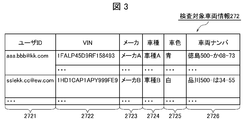
- FIG. 3 shows a logical configuration of the inspection target vehicle information 272.
- the inspection target vehicle information 272 includes a user ID column 2721, a VIN (Vehicle Identification Number) column 2722, a manufacturer column 2723, a vehicle type column 2724, a vehicle color column 2725, and a vehicle number column 2726.
- VIN Vehicle Identification Number
- the user ID column 2721 stores user identification information
- the VIN column 2722 stores identification information for identifying the automobile 1 to be inspected.
- the manufacturer column 2723 stores the name of the manufacturer of the automobile 1
- the vehicle type column 2724 stores the vehicle type of the automobile 1
- the vehicle color column 2725 stores the color of the automobile 1.
- the vehicle number column 2726 stores the vehicle number of the automobile 1.
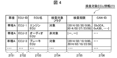
- FIG. 4 shows a logical configuration of the inspection target ECU information 273.
- the inspection target ECU information 273 includes a vehicle type column 2731, an ECU-ID column 2732, an ECU name column 2733, an inspection target flag column 2734, an inspection deadline column 2735, and a CAN-ID column 2736.
- the vehicle type column 2731 stores the vehicle type of the vehicle 1 to be inspected
- the ECU-ID column 2732 stores identification information for identifying the ECU 12 to be inspected
- the ECU name column 2733 stores the ECU name
- the inspection target flag column 2734 stores information on whether or not the inspection target is stored. For example, “target” or “non-target” is stored.
- the inspection deadline column 2735 stores the inspection deadline
- the CAN-ID column 2736 stores CAN identification information connected to the ECU 12 to be inspected.
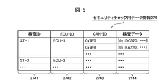
- FIG. 5 shows a logical configuration of the security check data information 274.
- the security check data information 274 includes an inspection ID column 2741, an ECU-ID column 2742, a CAN-ID column 2743, and an inspection data column 2744.
- the inspection ID column 2741 stores identification information for identifying the inspection using the security check data assigned to each ECU 12 to be inspected, and the ECU-ID column 2742 stores the inspection information using the security check data. Identification information for identifying the target ECU 12 is stored.
- the CAN-ID column 2743 stores CAN identification information connected to the ECU 12 to be inspected, and the inspection data column 2744 stores inspection data. For example, the data corresponding to the data field of the CAN protocol Is stored.
- FIG. 6 shows a logical configuration of the operation inspection data information 275. Similar to the security check data information 274, the operation inspection data information 275 includes an inspection ID column 2751, an ECU-ID column 2752, a CAN-ID column 2753, and an inspection data column 2754.
- the inspection ID column 2751 stores identification information for identifying the inspection using the operation inspection data assigned to each ECU 12 to be inspected, and the ECU-ID column 2752 stores the inspection information using the operation inspection data. Identification information for identifying the target ECU 12 is stored.
- the CAN-ID column 2753 stores the identification information of the CAN connected to the ECU 12 to be inspected, and the inspection data column 2754 stores the inspection data. For example, the data corresponding to the data field of the CAN protocol Is stored.
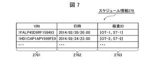
- FIG. 7 shows a logical configuration of the schedule information 276.
- the schedule information 276 includes a VIN column 2761, a date / time column 2762, and an examination ID column 2763.
- the VIN column 2761 stores identification information for identifying the automobile 1 to be inspected.
- the date / time column 2762 stores the inspection date / time approved by the user of the vehicle 1 to be inspected, and the inspection ID column 2762 stores identification information for identifying the inspection to be performed on the vehicle 1.
- FIG. 8 shows a logical configuration of the field structure information 277.
- the field structure information 277 includes a vehicle type column 2771, a CAN-ID column 2772, a detailed field ID column 2773, a segment ID column 2774, and a bit number column 2775.
- the vehicle type column 2771 stores the vehicle type of the vehicle 1 to be inspected
- the CAN-ID column 2772 stores identification information of the CAN connected to the ECU 12 to be inspected.
- the detailed field ID column 2773 stores identification information for identifying a category having a meaning obtained by classifying the data field of the CAN protocol in more detail based on the application design information of the ECU 12, and the category ID column 2774 contains The identification information for identifying the meaning of the data based on the application design information of the ECU 12 is stored.
- the category ID column 2774 a unique value for identifying a category of “valid digit, variable data, reservation data, dummy data, checksum, etc.” is stored.
- the bit number column 2775 stores the number of bits assigned to the detailed field ID.
- FIG. 9 shows a logical configuration of the field division information 278.
- the field division information 278 includes a division ID column 2781 and a division name column 2782.
- the section ID column 2781 stores identification information for identifying the type of data used in the data field of the CAN protocol.
- the category name column 2782 stores the name of the type of data used in the data field of the CAN protocol corresponding to the category ID.
- the name of the data type may be classified as “valid digits, variable data, reserved data, dummy data, checksum, etc.”.
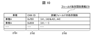
- FIG. 10 shows a logical configuration of the field dependency relationship information 279.
- the field dependency relationship information 279 includes a vehicle type column 2791, a CAN-ID column 2792, and a detailed field dependency relationship column 2793.
- the vehicle type column 2791 stores identification information of the vehicle 1 to be inspected
- the CAN-ID column 2792 stores identification information of the CAN connected to the ECU 12 to be inspected.
- the processing dependency of the detailed field ID (FIG. 8) in the application of the ECU 12 is determined based on the condition of branch processing in the design information of the application of the ECU 12, the usage as an argument of the function call, and the like. Information indicating the relationship is stored. For example, when there is a dependency relationship between A1 and A2 of the detailed field ID (FIG. 8), “A1 & A2” is stored using “&”.
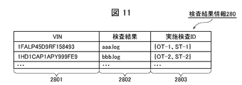
- FIG. 11 shows a logical configuration of the inspection result information 280.
- the inspection result information 280 includes a VIN column 2801, an inspection result column 2802, and an execution inspection ID column 2803.
- VIN column 2801 identification information for identifying the automobile 1 to be inspected is stored
- inspection result column 2802 the result of the executed inspection is stored as a log file.
- execution inspection ID column 2803 identification information for identifying the inspection performed on the automobile 1 is stored.
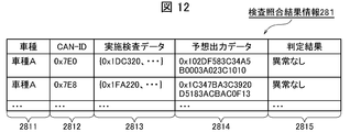
- FIG. 12 shows a logical configuration of the inspection verification result information 281.
- the inspection verification result information 281 includes a vehicle type column 2811, a CAN-ID column 2812, an execution inspection data column 2813, an expected output data column 2814, and a determination result column 2815.
- the vehicle type column 2811 stores the vehicle type of the vehicle 1 to be inspected
- the CAN-ID column 2812 stores identification information of the CAN connected to the ECU 12 to be inspected.
- the inspection data transmitted to the ECU 12 is stored in the execution inspection data column 2813, and the data expected to be output by the ECU 12 as a result of transmitting the inspection data performed to the ECU 12 is stored in the expected output data column 2814. Is done.
- the determination result column 2815 stores the result of comparison between the predicted output data and the output data stored in the log file of the inspection result (FIG. 11). For example, the output data is within the range of the predicted output data. If it is within the range, “no abnormality” is stored, and if it is out of the range, “abnormal” is stored.
- FIG. 13 shows a logical configuration of the inspection execution data information 1161.
- the inspection execution data information 1161 includes an execution order column 11611, an inspection ID column 11612, a CAN-ID column 11613, an inspection data column 11614, and a progress status column 11615.
- the execution order column 11611 stores the order in which the inspection data stored in the inspection data column 11614 is transmitted to the ECU 12, and the inspection ID column 11612 stores operation inspection data or security check associated with each ECU 12.
- the identification information for identifying the business data is stored.
- the CAN-ID column 11613 stores identification information of the CAN connected to the ECU 12 to be inspected, and the inspection data column 11614 stores inspection data (operation inspection data or security check data) transmitted to the ECU 12. ) Is stored.
- the progress status column 11615 stores information indicating whether or not the inspection using the inspection data stored in the inspection data column 11614 is completed. For example, the inspection data is transmitted to the ECU 12 and output from the ECU 12. “Complete” is stored at the timing when the data to be acquired is acquired.
- FIG. 14 shows a logical configuration of the inspection execution result information 1162.
- the inspection execution result information 1162 includes an inspection ID column 11621 and an inspection result column 11622.
- the inspection ID column 11621 stores identification information for identifying operation inspection data or security check data associated with each ECU.
- the inspection execution unit 113 transmits the inspection data stored in the inspection data column 11614 to the ECU 12, and the data output from the ECU 12 is stored, for example, “date, inspection transmitted to the ECU 12”. Log files in which “data for use, data output from ECU 12” and the like are recorded are stored.
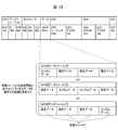
- FIG. 15 shows a data frame structure. This data frame structure is defined by ISO15031 of the International Organization for Standardization.
- the SOF (Start Of Frame) field is a field indicating the start of the data frame, and the arbitration field is composed of an ID (Identifier) indicating a transmission destination and an RTR (Remote Transmission Request), and is a field indicating the priority of the frame. is there.
- the controller field is a field indicating reserved bits and the number of data bytes.
- the ID constituting the arbitration field is a CAN-ID in the present embodiment, and the structure (classification) of the data field described later is determined by the CAN-ID.
- the data field is a field for storing the data body.
- security check data is generated by storing random data in a part or all of the data field.
- the security check data is generated by the inspection data generation unit 23 of the service providing server 2.
- the inspection data generation unit 23 first analyzes the structure (section) of the data field and divides the data into, for example, four sections. An analysis result is obtained. Next, the dependency relation of each section is analyzed, and finally, based on the dependency relation, random data is stored in any section with good inspection efficiency to generate security check data.
- the CRC field is a field for checking data frame errors.
- the ACK field is a field that indicates a signal for confirmation of normal reception
- the EOF (End Of Frame) field is a field that indicates the end of the data frame.
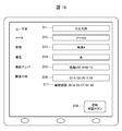
- FIG. 16 shows a screen configuration displayed by the screen display unit 31 of the terminal 3 with communication function. This screen is a screen for editing or approving in the terminal 3 with communication function when the inspection schedule is transmitted from the service providing server 2 to the terminal 3 with communication function.
- a user name registered as a user of the vehicle 1 to be inspected is displayed. This user name is acquired from the user name stored in the user name column 2713.
- the maker area 312 the maker name of the automobile 1 to be inspected is displayed.
- the manufacturer name is acquired from the manufacturer name stored in the manufacturer column 2723.
- the vehicle type of the automobile 1 to be inspected is displayed. This vehicle type is acquired from the vehicle type stored in the vehicle type column 2724.
- the vehicle color area 314 displays the vehicle color of the automobile 1 to be inspected. This vehicle color is acquired from the vehicle color stored in the vehicle color column 2725.
- the vehicle number area 315 the vehicle number of the vehicle 1 to be inspected is displayed. This vehicle number is acquired from the vehicle number stored in the vehicle number column 2726.
- the schedule created by the inspection planning unit 21 is displayed in an editable manner.
- the execution time limit area 317 the time limit of the inspection is displayed.
- the inspection deadline is acquired from the inspection deadline stored in the inspection deadline column 2735.
- the registration approval button 318 is a button to be pressed when approving that the inspection is executed at the inspection date and time displayed in the inspection date and time area 316.
- FIG. 17 shows a processing procedure for schedule registration processing. This schedule registration process is executed by the service providing server 2 and the terminal 3 with a communication function.
- the inspection planning unit 21 of the service providing server 2 transmits a notification of an inspection approval request (SP1).
- This inspection approval request notification is a notification requesting transmission of an ID and a password.
- the service execution confirmation unit 32 of the terminal 3 with the communication function receives the notification of the approval request for the inspection, the service execution confirmation unit 32 transmits the ID and password input by the user to the service providing server 2 (SP2).
- the inspection planning unit 21 when receiving the ID and password, the inspection planning unit 21 refers to the user information 271 and executes ID and password authentication processing (SP3). Then, when the ID and password are authenticated by the authentication process, the inspection planning unit 21 creates one or a plurality of inspection schedules with reference to the inspection target vehicle information 272 and the inspection target ECU information 273, and requests the approval of the created schedule. A notification is transmitted to the terminal 3 with a communication function (SP4).
- SP3 ID and password authentication processing
- the notification of the approval request for the schedule is a notification instructing to display the schedule together with various information included in the user information 271, the inspection target vehicle information 272, and the inspection target ECU information 273.
- the screen display unit 31 Upon receiving the notification of the schedule approval request, displays the schedule on the display screen together with various information included in the notification (SP5).
- the display screen displayed here is the display screen described with reference to FIG.
- the service execution confirmation unit 32 edits the schedule as necessary (SP6), and then approves the schedule by pressing the registration approval button 318 (SP7). Then, the service execution confirmation unit 32 transmits the approved schedule to the service providing server 2 (SP8). Upon receiving the schedule from the terminal 3 with communication function, the inspection planning unit 21 stores this schedule in the schedule information 276 (SP9).
- the inspection plan unit 21 transmits a registration completion notification for storing the schedule and notifying that the registration is completed (SP10).
- the screen display unit 31 displays a registration completion screen indicating that the registration has been completed (SP11), and ends this schedule registration process.
- FIG. 18 shows a detailed processing procedure of schedule registration processing on the terminal 3 side with communication function.
- the detailed process procedure of the process which the terminal 3 with a communication function performs in the schedule registration process of FIG. 17 is demonstrated.
- the service execution confirmation unit 32 of the terminal 3 with communication function determines whether or not the inspection approval request notification transmitted from the service providing server 2 has been received in the state of waiting for the inspection approval request (SP101) (SP102). . If the service execution confirmation unit 32 obtains a negative result in the determination at step SP102, the service execution confirmation unit 32 proceeds to step SP101 and enters a standby state.
- the service execution confirmation unit 32 transmits the ID and password to the service providing server 2, and then receives a notification of a schedule approval request from the service providing server 2.
- the schedule is displayed on the display screen together with various information (SP103).
- the service execution confirmation unit 32 determines whether or not schedule editing is instructed by the user's editing operation (SP104). When the service execution confirmation unit 32 obtains a negative result in the determination at step SP104, the service execution confirmation unit 32 proceeds to step SP106, and when it obtains a positive result, the service execution confirmation unit 32 edits the schedule (SP105).
- the service execution confirmation unit 32 edits the schedule within the range of the execution deadline displayed in the execution deadline area 317 and approves the schedule by pressing the registration approval button 318. Then, the service execution confirmation unit 32 transmits the approved schedule to the service providing server 2 (SP106).
- the service execution confirmation unit 32 determines whether or not a registration completion notification has been received (SP108) while waiting for registration completion of the schedule (SP107). If the service execution confirmation unit 32 obtains a negative result in the determination at step SP108, the service execution confirmation unit 32 proceeds to step SP107. On the other hand, when the service execution confirmation unit 32 obtains a positive result in the determination at step SP108, the service execution confirmation unit 32 displays a registration completion screen on the display screen (SP109), and ends the schedule registration process.
- FIG. 19 shows a detailed processing procedure of schedule registration processing on the service providing server 2 side.
- a detailed processing procedure of processing executed by the service providing server 2 in the schedule registration processing of FIG. 17 will be described.
- the inspection plan unit 21 of the service providing server 2 finishes the authentication process of the ID and password transmitted from the terminal 3 with the communication function, the inspection plan unit 21 refers to the inspection target ECU information 273 and includes one or more within the “inspection period”. A schedule is created (SP111).
- the inspection planning unit 21 acquires the user information 271 and the inspection target vehicle information 272 (SP112), and transmits the user information 271 and the like together with the created schedule to the terminal 3 with a communication function (SP113).
- the examination planning unit 21 determines whether or not the approved schedule has been received (SP115) while waiting for reception of the approved schedule in the terminal 3 with communication function (SP114).
- the inspection planning unit 21 proceeds to step SP114.
- the test plan unit 21 obtains a positive result in the determination at step SP115, it stores the received schedule in the schedule information 276 (SP116). Then, the inspection planning unit 21 transmits a registration completion notification to the terminal 3 with communication function (SP117), and ends the schedule registration process.
- FIG. 20 shows a series of processing procedures for ECU inspection processing. This ECU inspection process is executed by the gateway 11 of the automobile 1, the service providing server 2, and the terminal 3 with a communication function.
- the inspection control unit 22 of the service providing server 2 refers to the schedule information 276 regularly or irregularly to check the schedule by acquiring the “date and time” scheduled for inspection (SP21).
- the inspection control unit 22 determines whether there is a target inspection (SP22). If a negative result is obtained, the process returns to step SP21, and if an affirmative result is obtained, the process proceeds to step SP23.
- the inspection control unit 22 transmits an inspection execution notification to the terminal 3 with a communication function by the inspection data input unit 24 (SP23).
- the screen display unit 31 displays a reminder screen (SP24).
- the inspection data input unit 24 acquires inspection data from the security check data information 274 and operation inspection data information 275, and transmits the acquired inspection data to the gateway 11 of the vehicle 1 to be inspected (SP25). .
- the inspection execution control unit 111 of the gateway 11 Upon receipt of the inspection data, the inspection execution control unit 111 of the gateway 11 stores the received inspection data in the inspection execution data information 1161 (SP26). Next, the inspection execution control unit 111 checks the vehicle state of the automobile 1 (SP27). If the automobile 1 is not in the standby state (SP28: N), the inspection execution control unit 111 determines that the inspection is not possible and proceeds to step SP27.
- the standby state means that the automobile 1 is in a stopped state and a certain time has elapsed.
- the inspection execution control unit 111 acquires the inspection data stored in the inspection execution data information 1161, and transmits the inspection data acquired by the inspection execution unit 113 to the ECU 12. (SP29).
- the inspection execution control unit 111 acquires data output from the ECU 114 by the inspection monitoring unit 114, specifically captures the packet (SP30), and stores the captured packet in the inspection execution result information 1162.
- the inspection execution control unit 111 confirms whether inspection data to be transmitted to the ECU 12 remains in the inspection execution data information 1161 (SP31). If it remains, the process proceeds to step SP28. Shifts to step SP32. If the inspection is not completed even after a certain period of time has elapsed, a warning may be sent to the service providing server 2.
- the inspection execution control unit 111 transmits an inspection result completion notification indicating that the inspection is completed to the service providing server 2 when there is no inspection data to be transmitted to the ECU 12 (SP32).
- the inspection result collection unit 25 transmits a notification of the inspection result collection request to the gateway 11 (SP33).
- the inspection information acquisition unit 112 of the gateway 11 Upon receipt of the inspection result collection request notification, the inspection information acquisition unit 112 of the gateway 11 acquires the inspection execution result information 1162 (SP34), and transmits the acquired inspection execution result information 1162 to the service providing server 2 (SP35). Upon receiving the inspection execution result information 1162, the inspection result collection unit 25 of the service providing server 2 stores it in the inspection result information 280 (SP36).
- the inspection result analysis unit 26 analyzes the inspection result information by referring to the inspection result information 280 and the inspection verification result information 281 and comparing the output result actually output from the ECU 12 with the predicted output result. (SP37), the analysis result is determined (SP38), and the determination result is stored in the inspection verification result information 281.
- the inspection control unit 22 transmits the determination result to the terminal 3 with a communication function (SP39).
- the determination result may be transmitted to a dealer or an automobile manufacturer other than the terminal 3 with the communication function.
- the screen display unit 31 of the terminal 3 with communication function displays it on the display screen as the inspection result (SP40).
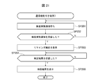
- FIG. 21 shows a detailed processing procedure of ECU inspection processing on the terminal 3 side with communication function.
- inspection process of FIG. 20 is demonstrated.
- the service execution confirmation unit 32 of the terminal 3 with communication function determines whether or not the inspection execution notification transmitted from the service providing server 2 has been received (SP201) while waiting for the inspection execution notification (SP201). If the service execution confirmation unit 32 obtains a negative result in the determination at step SP202, the service execution confirmation unit 32 proceeds to step SP201.
- the service execution confirmation unit 32 determines whether or not the determination result transmitted from the service providing server 2 has been received (SP204). If the service execution confirmation unit 32 obtains a negative result in the determination at step SP204, the service execution confirmation unit 32 waits until the determination result is received.
- the service display unit 31 displays the inspection result on the display screen by the screen display unit 31 (SP205), and ends the ECU inspection process.
- FIG. 22 shows a detailed processing procedure of ECU inspection processing on the service providing server 2 side.
- a detailed processing procedure of processing executed by the service providing server 2 in the ECU inspection processing of FIG. 20 will be described.
- the inspection data input unit 24 of the service providing server 2 refers to the schedule information 276 regularly or irregularly according to an instruction from the inspection control unit 22, and checks the schedule by acquiring the “date and time” of the inspection schedule ( SP211). Then, the inspection data input unit 24 determines whether there is an inspection to be performed (SP212).
- the inspection data input unit 24 obtains a negative result in the determination at step SP212, the inspection data input unit 24 proceeds to step SP211.
- the test data input unit 24 obtains a positive result in the determination at step SP212, it transmits a test execution notification to the terminal 3 with communication function (SP213).
- the inspection data input unit 24 acquires inspection data from the security check data information 274 and the operation inspection data information 275, and transmits this inspection data to the gateway 11 of the vehicle 1 to be inspected (SP214).
- the inspection control unit 22 determines whether or not the inspection result completion notification transmitted from the gateway 11 has been received (SP216) while waiting for the inspection result completion notification (SP215). If the inspection control unit 22 obtains a negative result in the determination at step SP216, the inspection control unit 22 proceeds to step SP215.
- the inspection result collection unit 25 transmits a notification of the inspection result collection request to the gateway 11 (SP217).
- the inspection result collection unit 25 determines whether or not the inspection execution result information 1162 transmitted from the gateway 11 has been received in a state waiting for the inspection result collection (SP218) (SP219).
- the inspection result collection unit 25 obtains a negative result in the determination at step SP219, the inspection result collection unit 25 proceeds to step SP218.
- the test result collection unit 25 obtains a positive result in the determination at step SP219, it stores the received test execution result information 1162 in the test result information 280.
- the inspection result analysis unit 26 refers to the inspection result information 280 and the inspection verification result information 281 and analyzes the inspection result by comparing the output result actually output from the ECU 12 with the expected output result. (SP220) When the output result is as expected, it is determined that there is no abnormality, and when the output result is not as expected, it is determined that there is an abnormality (SP221).
- the inspection control part 22 transmits a determination result to the terminal 3 with a communication function (SP222), and complete
- FIG. 23 shows a detailed processing procedure of ECU inspection processing on the gateway 11 side of the automobile 1.
- a detailed processing procedure of processing executed by the gateway 11 in the ECU inspection processing of FIG. 20 will be described.
- the inspection execution control unit 111 of the gateway 11 determines whether there is a processing request while waiting for a processing request from the service providing server 2 (SP231) (SP232). If the test execution control unit 111 obtains a negative result in the determination at step SP232, it proceeds to step SP231, and if it obtains a positive result, it determines the processing content (SP233).
- the inspection execution control unit 111 stores the received inspection data in the inspection execution data information 1161 when the processing content is an inspection execution request, that is, when the inspection data is received from the service providing server 2 (SP234). Next, the inspection execution control unit 111 checks the vehicle state of the automobile 1 (SP235), and determines whether the automobile 1 is in a standby state (SP236).
- the inspection execution control unit 111 causes the inspection execution unit 113 to perform a CAN protocol based on “CAN-ID” and “inspection data” of the inspection execution data information 1161. Is generated, and the generated message is transmitted to the ECU 12 (SP237).
- the inspection execution control unit 111 acquires data output from the ECU 12 by the inspection monitoring unit 114, specifically captures a packet and stores it in the inspection execution result information 1162 (SP238).
- the inspection execution control unit 111 updates the “progress status” of the inspection execution data information 1161 to “completed” (SP239).
- the inspection execution control unit 111 refers to the “progress status” of the inspection execution data information 1161 and confirms whether there is an item that is not “completed”, thereby checking the inspection data to be transmitted to the ECU 12. Is not left in the inspection execution data information 1161 (SP240).
- the inspection execution control unit 111 obtains a negative result in the determination at step SP240, the inspection execution control unit 111 proceeds to step SP236, and when an affirmative result is obtained, the inspection execution completion notification is transmitted to the service providing server 2 (SP243). End the process.
- step SP2366 if the vehicle 1 is not in the standby state (SP236: N), the vehicle 1 may wait until it enters the standby state, but here the inspection is temporarily stopped (SP241), and the temporary stop indicating that the vehicle 1 has stopped. A notification is transmitted to the service providing server 2 (SP243), and this ECU inspection process is terminated.
- step SP233 when the processing content is the inspection result collection request, that is, when the notification of the inspection result collection request is received from the service providing server 2, the inspection execution control unit 111 performs the inspection execution result information by the inspection information acquisition unit 112. 1162 is acquired (SP242), this inspection execution result information 1162 is transmitted to the service providing server 2 (SP243), and this ECU inspection process is terminated.
- FIG. 24 shows a processing procedure of security check data generation processing. This security check data generation process is executed by the service providing server 2 at any timing during the ECU inspection process (FIG. 20) or before the ECU inspection process.
- the inspection data generation unit 23 of the service providing server 2 refers to the inspection target ECU information 273 and acquires “ECU-ID” whose “inspection target flag” is “target” as the ECU-ID of the inspection target ( SP31).
- the inspection data generation unit 23 acquires “CAN-ID” associated with the ECU-ID specified as the inspection target (SP32).
- the inspection data generation unit 23 refers to the field structure information 277 by the field structure analysis unit 232 and acquires “detailed field ID” and “number of bits” associated with the CAN-ID acquired in step SP32.
- the field structure of the data field (FIG. 15) is analyzed (SP33).
- the field structure analysis unit 232 refers to the field structure information 277, and if the CAN-ID acquired in step SP32 is “0 ⁇ 7E0”, it is associated with the CAN-ID of “0 ⁇ 7E0”.
- the detailed field IDs of “A1”, “A2”, “A3”, and “A4” are acquired.
- the field structure analysis unit 232 acquires the number of bits of “8 bits”, “8 bits”, “16 bits”, and “32 bits” associated with the detailed field IDs of “A1” to “A4”. As a result, the field structure analysis unit 232 divides the data field structure into “A1” to “A4”, and each division is “8 bits”, “8 bits”, “16 bits”, and “32 bits”. It is possible to obtain an analysis result indicating that
- the field structure analysis unit 232 refers to the field structure information 277 and stores “D1”, “D2”, “D2”, and “D4” associated with the detailed field IDs “A1” to “A4”. Get the category ID and refer to the field category information 278 to get the category names of “significant digits”, “variable data”, and “dummy” associated with “D1”, “D2”, “D4” By doing so, it is possible to analyze the meaning indicated by the data stored in “A1” to “A4”.
- the inspection data generation unit 23 refers to the field dependency relationship information 279 by the dependency relationship analysis unit 231 and acquires the “detail field dependency” associated with the CAN-ID acquired in step SP32 ( SP34).
- the dependency relationship analysis unit 231 refers to the field dependency relationship information 279, and if the CAN-ID acquired in step SP32 is “0 ⁇ 7E0”, it is associated with the CAN-ID of “0 ⁇ 7E0”.
- Dependencies ⁇ A1, (A2 & A3), A4 ⁇ are acquired. In this case, there is a dependency between the data stored in the “A2” section and the data stored in the “A3” section.
- the inspection data generation unit 23 determines the allocation number of random data by the inspection data allocation unit 233 based on the “number of bits” acquired in step SP33 and the “detail field dependency” acquired in step SP34. (SP35).
- the inspection data generation unit 23 does not assign random data to all of the data fields having 64 bits in total, but from a viewpoint of inspection efficiency, the inspection data generation unit 23 randomly selects a position where more effective inspection can be realized in the data field. Allocate data.
- the inspection data generation unit 23 is dependent on “A2” and “A3”, and “A2” and “A3” are “8 bits” and “16 bits”, respectively. decide.
- the inspection data generation unit 23 may determine the number of random data allocated in units of dependency as described above, or the random data may be determined according to the priority according to the characteristics of the “section ID” of the field section information 278.
- the number of assignments may be determined. For example, random data may be assigned to “A1” and fixed data may be assigned to “A2” to “A4”.
- the inspection data generation unit 23 determines a range in which random data is used based on the number of data allocations determined in step SP35 by the inspection data allocation unit 233, and generates inspection data (SP36). Then, the inspection data generation unit 23 stores the generated data in the security check data information 274 (SP37).
- the inspection data generation unit 23 determines whether or not there remains a dependency for which inspection data has not been generated among the dependencies acquired in step SP34 (SP38). When the test data generation unit 23 obtains a negative result in the determination at step SP38, it proceeds to step SP36, and when it obtains a positive result, it ends this security check data generation process.
- the ECU 12 receives the data at the design stage of the ECU 12. Since the security check data that is not supposed to be transmitted is transmitted to the ECU 12 and it is determined whether or not the data output from the ECU 12 is within a normal range, the operation of the ECU 12 during operation is accurately determined. Can be inspected.
- the inspection result analysis unit 26 of the service providing server 2 refers to the inspection result information 280 and the inspection verification result information 281 to obtain the inspection result information 280.
- the analysis result is determined and the analysis result is determined (FIG. 20: SP37 and SP38).
- the gateway 11 of the automobile 1 includes the inspection result analysis unit 26 and the inspection verification result information 281.
- the unit 26 may analyze the inspection execution data information 1161 with reference to the inspection execution data information 1161 and the inspection collation result information 281 to determine the analysis result.
- FIG. 25 shows a processing procedure of ECU inspection processing in another embodiment.
- the gateway 11 analyzes the inspection result (SP31A), the analysis result is determined (SP32A), the gateway 11 acquires the determination result (SP36A), and the service providing server 2 (SP37A) is different from the ECU inspection process (FIG. 20) in the present embodiment described above in that (SP37A) is transmitted to (or the terminal 3 with direct communication function).
Landscapes
- Engineering & Computer Science (AREA)
- Physics & Mathematics (AREA)
- General Physics & Mathematics (AREA)
- Automation & Control Theory (AREA)
- Theoretical Computer Science (AREA)
- Computer Security & Cryptography (AREA)
- Mechanical Engineering (AREA)
- Computer Hardware Design (AREA)
- Software Systems (AREA)
- General Engineering & Computer Science (AREA)
- Vehicle Cleaning, Maintenance, Repair, Refitting, And Outriggers (AREA)
- Stored Programmes (AREA)
- Small-Scale Networks (AREA)
- Testing And Monitoring For Control Systems (AREA)
Abstract
【課題】運用時における制御装置の動作を正確に検査し得る検査装置、検査システム及び検査方法を提案する。 【解決手段】車載ネットワークに接続されたECUの動作を検査する検査装置において、ECUの動作を検査するために用いられる動作検査用データ及びセキュリティチェック用データの2つのデータをECUに送信し、ECUから出力されるデータを受信する検査実行制御部を備え、動作検査用データは、ECUの設計情報に基づいて予め生成されるデータであり、セキュリティチェック用データは、動作検査用データの一部又は全部をランダムデータに置き換えたデータであることを特徴とする。
Description
本発明は、自動車に搭載された制御装置の動作を検査する検査装置、検査システム及び検査方法に関し、特に車載ネットワークに接続された制御装置の動作を検査する検査装置、検査システム及び検査方法に適用して好適なものである。
近年、自動車に搭載された複数の制御装置(Electronic Control Unit : ECU)を車載ネットワーク(Controller Area Network : CAN)に接続し、この車載ネットワークを介して、複数の制御装置を連携して動作させる技術が開発されている。
複数のECUには、例えばエンジンの制御を行うエンジンECU、シフトチェンジの制御を行うトランスミッションECU及びブレーキ油圧の調整を行うブレーキECU等がある。そして特許文献1には、これら複数のECUが連携して動作する場合に連携動作の不具合を判断し、故障個所を特定する技術が開示されている。
具体的に特許文献1には、車載ネットワークを介してECU間で送受信されるデータに基づいて、連係動作による不具合の発生を判断する不具合判断手段と、不具合の発生が判断されると、不具合に対応させて予め用意された検査診断プログラムを取得するプログラム取得手段と、検査診断プログラムを実行することによりECUに対して対応処理を実行させて、対応処理の実行によりECUから送信される情報に基づいて、故障個所を特定する故障個所特定手段とを備えた故障診断システムが開示されている。
しかし特許文献1に記載の故障診断システムでは、予め用意された検査診断プログラムを用いて故障個所を特定するものであり、検査診断プログラムはECUの設計情報に基づいて、運用前に予め生成されるプログラムであることから、運用時において設計段階では想定されないデータがECUに送信された場合にECUが正常に動作するか否かを判断することはできない。
すなわち故障(機能不全)についてはその故障を特定することはできるが、動作はしているがその動作が正常であるのか異常であるのかを正確に判断することはできない。
本発明は以上の点を考慮してなされたものであり、運用時におけるECUの動作を正確に検査し得る検査装置、検査システム及び検査方法を提案する。
かかる課題を解決するために、本発明の検査装置においては、ECUの動作を検査するために用いられる動作検査用データ及びセキュリティチェック用データの2つのデータをECUに送信し、ECUから出力されるデータを受信する検査実行制御部を備え、動作検査用データは、ECUの設計情報に基づいて予め生成されるデータであり、セキュリティチェック用データは、動作検査用データの一部又は全部をランダムデータに置き換えたデータであることを特徴とする。
またかかる課題を解決するために、本発明の検査システムにおいては、ECUの動作を検査するスケジュールを計画する検査計画部と、ECUの動作を検査するために用いられる動作検査用データ及びセキュリティチェック用データの2つのデータを生成する検査データ生成部と、計画されたスケジュールに従って、生成された2つのデータを外部に送信する検査制御部とを備えるサービス提供サーバと、サービス提供サーバから送信される動作検査用データ及びセキュリティチェック用データの2つのデータを受信した場合、受信した2つのデータをECUに送信し、ECUから出力されるデータを受信した場合、受信したデータを含む検査実行結果情報をサービス提供サーバに送信するゲートウェイとを備え、動作検査用データは、ECUの設計情報に基づいて予め生成されるデータであり、セキュリティチェック用データは、動作検査用データの一部又は全部をランダムデータに置き換えたデータであることを特徴とする。
またかかる課題を解決するために、本発明の検査方法においては、検査計画部が、ECUの動作を検査するスケジュールを計画する第1のステップと、検査データ生成部が、ECUの動作を検査するために用いられる動作検査用データ及びセキュリティチェック用データの2つのデータを生成する第2のステップと、検査制御部が、計画されたスケジュールに従って、生成された2つのデータを外部に送信する第3のステップとを備え、ゲートウェイが、サービス提供サーバから送信される動作検査用データ及びセキュリティチェック用データの2つのデータを受信した場合、受信した2つのデータをECUに送信し、ECUから出力されるデータを受信した場合、受信したデータを含む検査実行結果情報をサービス提供サーバに送信する第4のステップとを備え、動作検査用データは、ECUの設計情報に基づいて予め生成されるデータであり、セキュリティチェック用データは、動作検査用データの一部又は全部をランダムデータに置き換えたデータであることを特徴とする。
本発明によれば、運用時におけるECUの動作を正確に検査することができる。
以下図面について、本発明の一実施の形態を詳述する。
(1)全体構成
図1は、本実施の形態における検査システム5の全体構成を示す。検査システム5は、自動車1、サービス提供サーバ2及び通信機能付き端末3を備えて構成される。またこれら自動車1、サービス提供サーバ2及び通信機能付き端末3は、通信網4を介して互いに通信可能に接続される。通信網4は、例えば携帯電話網又は無線LAN(Local Area Network)である。
図1は、本実施の形態における検査システム5の全体構成を示す。検査システム5は、自動車1、サービス提供サーバ2及び通信機能付き端末3を備えて構成される。またこれら自動車1、サービス提供サーバ2及び通信機能付き端末3は、通信網4を介して互いに通信可能に接続される。通信網4は、例えば携帯電話網又は無線LAN(Local Area Network)である。
自動車1は、ゲートウェイ11及び複数のECU(Electronic Control Unit)12を備えて構成される。ゲートウェイ11と各ECU12との間は、CAN(Controller Area Network)と呼ばれる車載ネットワークにより接続される。
ゲートウェイ11は、ここでは検査装置として機能する端末であり、検査実行制御部111、検査情報取得部112、検査実行部113、検査監視部114、通信部115及び検査情報管理部116を備えて構成される。
検査実行制御部111は、通信部115を介して受信した検査実行データ情報1161を検査情報管理部116に格納し、また検査情報管理部116に格納した検査実行データ情報1161を取得してECU12に送信する。検査実行データ情報1161には、動作検査用データ及びセキュリティチェック用データがある。
動作検査用データとは、設計情報に基づいて、設計段階で予め生成されるECU12のテスト用のデータである。詳細については後述する(図6)。またセキュリティチェック用データとは、実際の運用時においてECU12の動作が正常であるのか異常であるのかを検査及び診断するためのテスト用のデータである。詳細については後述する(図5)。なおこれらをまとめて検査用データと呼ぶ場合がある。
検査情報取得部112は、検査情報管理部116に格納されている検査実行結果情報1162を取得し、通信部115を介して、この検査実行結果情報1162をサービス提供サーバ2に送信する。検査実行部113は、検査実行制御部111からの検査実行要求に基づいて、動作検査用データ及びセキュリティチェック用データをECU12に送信する。
検査監視部114は、動作検査用データ及びセキュリティチェック用データに基づいてECU12から出力されるデータを監視及び取得し、取得したデータを検査実行結果情報1162として検査情報管理部116に格納する。
ECU12は、自動車1が備える各種機器を制御する制御装置である。ECU12には、例えばエンジンの制御を行うエンジンECU、シフトチェンジの制御を行うトランスミッションECU及びブレーキ油圧の調整を行うブレーキECU等がある。
サービス提供サーバ2は、検査計画部21、検査制御部22、検査データ生成部23、依存関係解析部231、フィールド構造解析部232、検査データ割当部233、検査データ投入部24、検査結果回収部25、検査結果解析部26及び検査サービス情報管理部27を備えて構成される。
検査計画部21は、ECU12に対して実行する検査のスケジュールを計画し、計画したスケジュールを自動車1の利用者が所有する通信機能付き端末3に送信し、通信機能付き端末3において承認されたスケジュールを受信して、このスケジュールを検査サービス情報管理部27に格納する。
検査制御部22は、検査データ生成部23、検査データ投入部24、検査結果回収部25及び検査結果解析部26の動作を統括的に制御する。
検査データ生成部23は、依存関係解析部231、フィールド構造解析部232及び検査データ割当部233を用いてセキュリティチェック用データを生成し、生成したセキュリティチェック用データを検査サービス情報管理部27に格納する。
検査データ投入部24は、検査の実行を通知するお知らせを自動車1の利用者が所有する通信機能付き端末3に送信し、検査サービス情報管理部27からセキュリティチェック用データ及び動作検査用データを取得して検査対象の自動車1に送信する。
検査結果回収部25は、ゲートウェイ11から検査完了通知を受信すると、検査実行結果情報1162の回収要求をゲートウェイ11に送信し、ゲートウェイ11から回収した検査実行結果情報1162を検査サービス情報管理部27に格納する。
検査結果解析部26は、検査サービス情報管理部27から検査結果情報280及び検査照合結果情報281を取得し、両者を比較して、ECU12から出力された信号が異常であるか否かを解析する。
検査サービス情報管理部27は、サービス提供サーバ2の動作に必要な各種情報(271~281)を備える。各種情報の詳細については後述する(図2~図14)。
通信機能付き端末3は、画面表示部31、サービス実行確認部32及び通信部33を備えて構成される。画面表示部31は、サービス提供サーバ2により計画された検査のスケジュールを表示画面に表示し、またサービス提供サーバ2により解析された検査結果を表示画面に表示する。サービス実行確認部32は、表示画面に表示された検査のスケジュールについて、編集及び承認の処理を実行する。
(2)テーブル構成
以下図2~図12を参照して、サービス提供サーバ2の検査サービス情報管理部27に格納されている各種情報について説明する。
以下図2~図12を参照して、サービス提供サーバ2の検査サービス情報管理部27に格納されている各種情報について説明する。
図2は、ユーザ情報271の論理構成を示す。ユーザ情報271は、ユーザID欄2711、ユーザPASS欄2712及びユーザ名欄2713から構成される。ユーザID欄2711には、検査システム5を利用するユーザの識別情報が格納され、ユーザPASS欄2712には、ユーザのパスワードが格納される。またユーザ名欄2713には、ユーザ名が格納される。
図3は、検査対象車両情報272の論理構成を示す。検査対象車両情報272は、ユーザID欄2721、VIN(Vehicle Identification Number)欄2722、メーカ欄2723、車種欄2724、車色欄2725及び車両ナンバ欄2726から構成される。
ユーザID欄2721には、ユーザの識別情報が格納され、VIN欄2722には、検査対象の自動車1を識別する識別情報が格納される。またメーカ欄2723には、自動車1のメーカ名が格納され、車種欄2724には、自動車1の車種が格納され、車色欄2725には、自動車1の色が格納される。また車両ナンバ欄2726には、自動車1の車両ナンバが格納される。
図4は、検査対象ECU情報273の論理構成を示す。検査対象ECU情報273は、車種欄2731、ECU-ID欄2732、ECU名欄2733、検査対象フラグ欄2734、検査期限欄2735及びCAN-ID欄2736から構成される。
車種欄2731には、検査対象の自動車1の車種が格納され、ECU-ID欄2732には、検査対象のECU12を識別する識別情報が格納される。またECU名欄2733には、ECU名が格納され、検査対象フラグ欄2734には、検査対象であるか否かの情報が格納され、例えば「対象」又は「非対象」が格納される。
また検査期限欄2735には、検査の期限が格納され、CAN-ID欄2736には、検査対象のECU12が接続しているCANの識別情報が格納される。
図5は、セキュリティチェック用データ情報274の論理構成を示す。セキュリティチェック用データ情報274は、検査ID欄2741、ECU-ID欄2742、CAN-ID欄2743及び検査データ欄2744から構成される。
検査ID欄2741には、検査対象のECU12ごとに割り当てられたセキュリティチェック用データを用いた検査を識別する識別情報が格納され、ECU-ID欄2742には、セキュリティチェック用データを用いた検査の対象となるECU12を識別する識別情報が格納される。
またCAN-ID欄2743には、検査対象のECU12が接続しているCANの識別情報が格納され、検査データ欄2744には、検査用データが格納され、例えばCANプロトコルのデータフィールドに該当するデータが格納される。
図6は、動作検査用データ情報275の論理構成を示す。動作検査用データ情報275は、セキュリティチェック用データ情報274と同様、検査ID欄2751、ECU-ID欄2752、CAN-ID欄2753及び検査データ欄2754から構成される。
検査ID欄2751には、検査対象のECU12ごとに割り当てられた動作検査用データを用いた検査を識別する識別情報が格納され、ECU-ID欄2752には、動作検査用データを用いた検査の対象となるECU12を識別する識別情報が格納される。
またCAN-ID欄2753には、検査対象のECU12が接続しているCANの識別情報が格納され、検査データ欄2754には、検査用データが格納され、例えばCANプロトコルのデータフィールドに該当するデータが格納される。
図7は、スケジュール情報276の論理構成を示す。スケジュール情報276は、VIN欄2761、日時欄2762及び検査ID欄2763から構成される。VIN欄2761には、検査対象の自動車1を識別する識別情報が格納される。
日時欄2762には、検査対象の自動車1の利用者が承認した検査日時が格納され、検査ID欄2763には、自動車1に対して実行する検査を識別する識別情報が格納される。
図8は、フィールド構造情報277の論理構成を示す。フィールド構造情報277は、車種欄2771、CAN-ID欄2772、詳細フィールドID欄2773、区分ID欄2774及びビット数欄2775から構成される。
車種欄2771には、検査対象の自動車1の車種が格納され、CAN-ID欄2772には、検査対象のECU12が接続しているCANの識別情報が格納される。
また詳細フィールドID欄2773には、ECU12のアプリケーションの設計情報に基づいて、CANプロトコルのデータフィールドをより詳細に分類した意味を持つ区分を識別する識別情報が格納され、区分ID欄2774には、ECU12のアプリケーションの設計情報に基づいてデータの持つ意味を識別する識別情報が格納される。
例えば区分ID欄2774には、「有効桁、可変データ、予約データ、ダミーデータ、チェックサム等」の区分を識別するための固有値が格納される。ビット数欄2775には、詳細フィールドIDに割り当てられているビット数が格納される。
図9は、フィールド区分情報278の論理構成を示す。フィールド区分情報278は、区分ID欄2781及び区分名称欄2782から構成される。区分ID欄2781には、CANプロトコルのデータフィールドで用いられるデータの種類を識別する識別情報が格納される。
また区分名称欄2782には、区分IDに対応するCANプロトコルのデータフィールドで用いられるデータの種類の名称が格納される。例えばデータの種類の名称は、「有効桁、可変データ、予約データ、ダミーデータ、チェックサム等」のように区分してもよい。
図10は、フィールド依存関係情報279の論理構成を示す。フィールド依存関係情報279は、車種欄2791、CAN-ID欄2792及び詳細フィールドの依存関係欄2793から構成される。車種欄2791には、検査対象の自動車1の識別情報が格納され、CAN-ID欄2792には、検査対象のECU12が接続しているCANの識別情報が格納される。
詳細フィールドの依存関係欄2793には、ECU12のアプリケーションの設計情報における分岐処理の条件や関数呼び出しの引数としての使われ方等に基づいてECU12のアプリケーションにおける詳細フィールドID(図8)の処理依存の関係を示す情報が格納され、例えば詳細フィールドID(図8)のA1とA2とに依存関係がある場合には「&」を用いて「A1&A2」が格納される。
図11は、検査結果情報280の論理構成を示す。検査結果情報280は、VIN欄2801、検査結果欄2802及び実施検査ID欄2803から構成される。VIN欄2801には、検査対象の自動車1を識別する識別情報が格納され、検査結果欄2802には、実行された検査の結果がログファイルとして格納される。また実施検査ID欄2803には、自動車1に対して実行した検査を識別する識別情報が格納される。
図12は、検査照合結果情報281の論理構成を示す。検査照合結果情報281は、車種欄2811、CAN-ID欄2812、実施検査データ欄2813、予想出力データ欄2814及び判定結果欄2815から構成される。
車種欄2811には、検査対象の自動車1の車種が格納され、CAN-ID欄2812には、検査対象のECU12が接続しているCANの識別情報が格納される。
また実施検査データ欄2813には、ECU12に送信した検査用データが格納され、予想出力データ欄2814には、実施した検査用データをECU12に送信した結果、ECU12が出力すると予想されるデータが格納される。
また判定結果欄2815には、予想出力データと、検査結果(図11)のログファイルに格納されている出力データとを比較して判定した結果が格納され、例えば出力データが予想出力データの範囲内である場合には「異常なし」が格納され、範囲外である場合には「異常あり」が格納される。
次いで以下図13及び図14を参照して、自動車1の検査情報管理部116に格納されている各種情報について説明する。
図13は、検査実行データ情報1161の論理構成を示す。検査実行データ情報1161は、実行順欄11611、検査ID欄11612、CAN-ID欄11613、検査データ欄11614及び進捗状況欄11615から構成される。
実行順欄11611には、検査データ欄11614に格納されている検査用データをECU12に送信する順序が格納され、検査ID欄11612には、ECU12ごとに紐付けられた動作検査用データ又はセキュリティチェック用データを識別する識別情報が格納される。
またCAN-ID欄11613には、検査対象のECU12が接続しているCANの識別情報が格納され、検査データ欄11614には、ECU12に送信する検査用データ(動作検査用データ又はセキュリティチェック用データ)が格納される。
また進捗状況欄11615には、検査データ欄11614に格納されている検査用データを用いた検査が完了したか否かの情報が格納され、例えば検査用データをECU12に送信し、ECU12から出力されるデータを取得したタイミングで「完了」が格納される。
図14は、検査実行結果情報1162の論理構成を示す。検査実行結果情報1162は、検査ID欄11621及び検査結果欄11622から構成される。検査ID欄11621には、ECUごとに紐付けられた動作検査用データ又はセキュリティチェック用データを識別する識別情報が格納される。
また検査結果欄11622には、検査実行部113が検査データ欄11614に格納されている検査用データをECU12に送信し、ECU12から出力されたデータが格納され、例えば「日付、ECU12に送信した検査用データ、ECU12から出力されたデータ」等を記録したログファイルが格納される。
(3)データ構造
図15は、データフレーム構造を示す。このデータフレーム構造は、国際標準化機構のISO15031により規定されている。
図15は、データフレーム構造を示す。このデータフレーム構造は、国際標準化機構のISO15031により規定されている。
SOF(Start Of Frame)フィールドは、データフレームの開始を示すフィールドであり、アービトレーションフィールドは、送信先を示すID(Identifier)及びRTR(Remote Transmission Request)から構成され、フレームの優先順位を示すフィールドである。コントローラフィールドは、予約ビット及びデータのバイト数を示すフィールドである。
なおアービトレーションフィールドを構成するIDは、本実施の形態においてはCAN-IDであり、CAN-IDにより、後述するデータフィールドの構造(区分)が定められている。
データフィールドは、データ本体を格納するフィールドである。本実施の形態においては、このデータフィールドの一部又は全部にランダムデータを格納することにより、セキュリティチェック用データを生成している。なおセキュリティチェック用データは、サービス提供サーバ2の検査データ生成部23により生成される。
セキュリティチェック用データの生成処理の詳細については後述するが(図24)、ここで簡単に説明すると、検査データ生成部23により、まずデータフィールドの構造(区分)を解析し、例えば4つに区分されているという解析結果を得る。次に各区分の依存関係を解析し、最後に依存関係に基づいて、検査効率の良い何れかの区分にランダムデータを格納してセキュリティチェック用データを生成する。
またCRCフィールドは、データフレームの誤りをチェックするフィールドである。またACKフィールドは、正常に受信した確認の合図を示すフィールドであり、EOF(End Of Frame)フィールドは、データフレームの終了を示すフィールドである。
(4)画面構成
図16は、通信機能付き端末3の画面表示部31により表示される画面構成を示す。この画面は、検査のスケジュールがサービス提供サーバ2から通信機能付き端末3に送信された場合に通信機能付き端末3において編集又は承認する際の画面である。
図16は、通信機能付き端末3の画面表示部31により表示される画面構成を示す。この画面は、検査のスケジュールがサービス提供サーバ2から通信機能付き端末3に送信された場合に通信機能付き端末3において編集又は承認する際の画面である。
ユーザ名領域311には、検査対象の自動車1の利用者として登録されているユーザ名が表示される。このユーザ名は、ユーザ名欄2713に格納されているユーザ名から取得される。メーカ領域312には、検査対象の自動車1のメーカ名が表示される。このメーカ名は、メーカ欄2723に格納されているメーカ名から取得される。
また車種領域313には、検査対象の自動車1の車種が表示される。この車種は、車種欄2724に格納されている車種から取得される。車色領域314には、検査対象の自動車1の車色が表示される。この車色は、車色欄2725に格納されている車色から取得される。車両ナンバ領域315には、検査対象の自動車1の車両ナンバが表示される。この車両ナンバは、車両ナンバ欄2726に格納されている車両ナンバから取得される。
また検査日時領域316には、検査計画部21が作成したスケジュールが編集可能に表示される。実施期限領域317には、検査の期限が表示される。この検査の期限は、検査期限欄2735に格納されている検査の期限から取得される。また登録承認ボタン318は、検査日時領域316に表示される検査日時で検査が実行されることを承認する際に押下するためのボタンである。
(5)フローチャート
図17は、スケジュール登録処理の処理手順を示す。このスケジュール登録処理は、サービス提供サーバ2及び通信機能付き端末3により実行される。
図17は、スケジュール登録処理の処理手順を示す。このスケジュール登録処理は、サービス提供サーバ2及び通信機能付き端末3により実行される。
まずサービス提供サーバ2の検査計画部21は、検査の承認依頼の通知を送信する(SP1)。この検査の承認依頼の通知は、ID及びパスワードの送信を要求する通知である。通信機能付き端末3のサービス実行確認部32は、この検査の承認依頼の通知を受信すると、利用者が入力したID及びパスワードをサービス提供サーバ2に送信する(SP2)。
次いで検査計画部21は、ID及びパスワードを受信すると、ユーザ情報271を参照してID及びパスワードの認証処理を実行する(SP3)。そして検査計画部21は、認証処理によりID及びパスワードを認証すると、検査対象車両情報272及び検査対象ECU情報273を参照して一又は複数の検査のスケジュールを作成し、作成したスケジュールの承認依頼の通知を通信機能付き端末3に送信する(SP4)。
このスケジュールの承認依頼の通知は、ユーザ情報271、検査対象車両情報272及び検査対象ECU情報273に含まれる各種情報とともにスケジュールを表示することを指示する通知である。画面表示部31は、スケジュールの承認依頼の通知を受信すると、この通知に含まれる各種情報とともにスケジュールを表示画面に表示する(SP5)。なおここで表示される表示画面は、図16で説明した表示画面である。
サービス実行確認部32は、必要に応じてスケジュールを編集した後(SP6)、登録承認ボタン318の押下によりスケジュールを承認する(SP7)。そしてサービス実行確認部32は、承認したスケジュールをサービス提供サーバ2に送信する(SP8)。検査計画部21は、通信機能付き端末3からのスケジュールを受信すると、このスケジュールをスケジュール情報276に格納する(SP9)。
そして検査計画部21は、スケジュールを格納して登録が完了したことを通知する登録完了通知を送信する(SP10)。画面表示部31は、登録完了通知を受信すると、登録が完了したことを示す登録完了画面を表示して(SP11)、このスケジュール登録処理を終了する。
図18は、通信機能付き端末3側のスケジュール登録処理の詳細な処理手順を示す。ここでは、図17のスケジュール登録処理において通信機能付き端末3が実行する処理の詳細な処理手順について説明する。
通信機能付き端末3のサービス実行確認部32は、検査承認依頼待ちの状態において(SP101)、サービス提供サーバ2から送信された検査の承認依頼の通知を受信したか否かを判断する(SP102)。サービス実行確認部32は、ステップSP102の判断で否定結果を得ると、ステップSP101に移行して待機状態となる。
これに対し、サービス実行確認部32は、ステップSP102の判断で肯定結果を得ると、ID及びパスワードをサービス提供サーバ2に送信し、その後サービス提供サーバ2からのスケジュールの承認依頼の通知を受信すると、各種情報とともにスケジュールを表示画面に表示する(SP103)。
サービス実行確認部32は、利用者の編集操作によりスケジュールの編集が指示されたか否かを判断する(SP104)。サービス実行確認部32は、ステップSP104の判断で否定結果を得ると、ステップSP106に移行し、肯定結果を得るとスケジュールを編集する(SP105)。
次いでサービス実行確認部32は、実施期限領域317に表示された実施期限の範囲内でスケジュールを編集し、登録承認ボタン318の押下によりスケジュールを承認する。そしてサービス実行確認部32は、承認したスケジュールをサービス提供サーバ2に送信する(SP106)。
サービス実行確認部32は、スケジュールの登録完了待ちの状態において(SP107)、登録完了通知を受信したか否かを判断する(SP108)。サービス実行確認部32は、ステップSP108の判断で否定結果を得ると、ステップSP107に移行する。これに対し、サービス実行確認部32は、ステップSP108の判断で肯定結果を得ると、登録完了画面を表示画面に表示して(SP109)、このスケジュール登録処理を終了する。
図19は、サービス提供サーバ2側のスケジュール登録処理の詳細な処理手順を示す。ここでは、図17のスケジュール登録処理においてサービス提供サーバ2が実行する処理の詳細な処理手順について説明する。
サービス提供サーバ2の検査計画部21は、通信機能付き端末3から送信されたID及びパスワードの認証処理を終了すると、検査対象ECU情報273を参照して、「検査期限」内で一又は複数のスケジュールを作成する(SP111)。
次いで検査計画部21は、ユーザ情報271及び検査対象車両情報272を取得し(SP112)、作成したスケジュールとともにユーザ情報271等を通信機能付き端末3に送信する(SP113)。次いで検査計画部21は、通信機能付き端末3において承認されたスケジュールの受信待ちの状態において(SP114)、承認されたスケジュールを受信したか否かを判断する(SP115)。
検査計画部21は、ステップSP115の判断で否定結果を得ると、ステップSP114に移行する。これに対し、検査計画部21は、ステップSP115の判断で肯定結果を得ると、受信したスケジュールをスケジュール情報276に格納する(SP116)。そして検査計画部21は、登録完了通知を通信機能付き端末3に送信して(SP117)、このスケジュール登録処理を終了する。
図20は、ECU検査処理の一連の処理手順を示す。このECU検査処理は、自動車1のゲートウェイ11、サービス提供サーバ2及び通信機能付き端末3により実行される。
まずサービス提供サーバ2の検査制御部22は、定期的又は不定期にスケジュール情報276を参照して、検査予定の「日時」を取得することによりスケジュールをチェックする(SP21)。次いで検査制御部22は、対象となる検査があるか否かを判断し(SP22)、否定結果を得るとステップSP21に戻り、肯定結果を得るとステップSP23に移行する。
次いで検査制御部22は、検査データ投入部24により検査実施通知を通信機能付き端末3に送信する(SP23)。画面表示部31は、検査実施通知を受信すると、リマインダ画面を表示する(SP24)。一方で検査データ投入部24は、セキュリティチェック用データ情報274及び動作検査用データ情報275から検査用データを取得し、取得した検査用データを検査対象の自動車1のゲートウェイ11に送信する(SP25)。
ゲートウェイ11の検査実行制御部111は、検査データを受信すると、受信した検査用データを検査実行データ情報1161に格納する(SP26)。次いで検査実行制御部111は、自動車1の車両状態を確認し(SP27)、自動車1がスタンバイ状態でない場合(SP28:N)、検査可能な状態でないと判断してステップSP27に移行する。
なおスタンバイ状態とは、自動車1が停止状態であって、かつ、一定時間が経過した状態であることをいう。検査実行制御部111は、自動車1がスタンバイ状態である場合(SP28:Y)、検査実行データ情報1161に格納した検査用データを取得し、検査実行部113により取得した検査用データをECU12に送信する(SP29)。
次いで検査実行制御部111は、検査監視部114によりECU114から出力されるデータを取得し、具体的にはパケットをキャプチャして(SP30)、キャプチャしたパケットを検査実行結果情報1162に格納する。
次いで検査実行制御部111は、ECU12に送信すべき検査用データが検査実行データ情報1161に残っていないか確認し(SP31)、残っている場合にはステップSP28に移行し、残っていない場合にはステップSP32に移行する。なお一定期間が経過しても検査が完了していない場合には、サービス提供サーバ2に警告を通知するとしてもよい。
検査実行制御部111は、ECU12に送信すべき検査用データが残っていない場合には検査が完了したことを示す検査結果完了通知をサービス提供サーバ2に送信する(SP32)。サービス提供サーバ2の検査制御部22は、検査結果完了通知を受信すると、検査結果回収部25により検査結果回収依頼の通知をゲートウェイ11に送信する(SP33)。
ゲートウェイ11の検査情報取得部112は、検査結果回収依頼の通知を受信すると、検査実行結果情報1162を取得し(SP34)、取得した検査実行結果情報1162をサービス提供サーバ2に送信する(SP35)。サービス提供サーバ2の検査結果回収部25は、検査実行結果情報1162を受信すると、検査結果情報280に格納する(SP36)。
次いで検査結果解析部26は、検査結果情報280及び検査照合結果情報281を参照して、ECU12から実際に出力された出力結果と、予測される出力結果とを比較することにより検査結果情報を解析し(SP37)、解析結果を判定し(SP38)、判定結果を検査照合結果情報281に格納する。
そして検査制御部22は、判定結果を通信機能付き端末3に送信する(SP39)。なお判定結果は通信機能付き端末3以外にもディーラや自動車メーカ等に送信するとしてもよい。通信機能付き端末3の画面表示部31は、判定結果を受信すると、検査結果として表示画面に表示する(SP40)。以上によりECU検査処理の一連の処理が終了する。
図21は、通信機能付き端末3側のECU検査処理の詳細な処理手順を示す。ここでは、図20のECU検査処理において通信機能付き端末3が実行する処理の詳細な処理手順について説明する。
通信機能付き端末3のサービス実行確認部32は、検査実施通知待ちの状態において(SP201)、サービス提供サーバ2から送信される検査実施通知を受信したか否かを判断する(SP202)。サービス実行確認部32は、ステップSP202の判断で否定結果を得ると、ステップSP201に移行する。
これに対し、サービス実行確認部32は、ステップSP202の判断で肯定結果を得ると、リマインダ画面を表示画面に表示する(SP203)。次いでサービス実行確認部32は、サービス提供サーバ2から送信される判定結果を受信したか否かを判断する(SP204)。サービス実行確認部32は、ステップSP204の判断で否定結果を得ると、判定結果を受信するまで待機する。
これに対し、サービス実行確認部32は、ステップSP204の判断で肯定結果を得ると、画面表示部31により検査結果を表示画面に表示して(SP205)、このECU検査処理を終了する。
図22は、サービス提供サーバ2側のECU検査処理の詳細な処理手順を示す。ここでは、図20のECU検査処理においてサービス提供サーバ2が実行する処理の詳細な処理手順について説明する。
サービス提供サーバ2の検査データ投入部24は、検査制御部22からの指示により定期的又は不定期にスケジュール情報276を参照して、検査予定の「日時」を取得することによりスケジュールをチェックする(SP211)。そして検査データ投入部24は、実施すべき検査があるか否かを判断する(SP212)。
検査データ投入部24は、ステップSP212の判断で否定結果を得ると、ステップSP211に移行する。これに対し、検査データ投入部24は、ステップSP212の判断で肯定結果を得ると、検査実施通知を通信機能付き端末3に送信する(SP213)。
次いで検査データ投入部24は、セキュリティチェック用データ情報274及び動作検査用データ情報275から検査用データを取得し、この検査用データを検査対象の自動車1のゲートウェイ11に送信する(SP214)。
次いで検査制御部22は、検査結果完了通知待ちの状態において(SP215)、ゲートウェイ11から送信される検査結果完了通知を受信したか否かを判断する(SP216)。検査制御部22は、ステップSP216の判断で否定結果を得ると、ステップSP215に移行する。
これに対し、検査制御部22は、ステップSP216の判断で否定結果を得ると、検査結果回収部25により検査結果回収依頼の通知をゲートウェイ11に送信する(SP217)。次いで検査結果回収部25は、検査結果回収待ちの状態において(SP218)、ゲートウェイ11から送信される検査実行結果情報1162を受信したか否かを判断する(SP219)。
検査結果回収部25は、ステップSP219の判断で否定結果を得ると、ステップSP218に移行する。これに対し、検査結果回収部25は、ステップSP219の判断で肯定結果を得ると、受信した検査実行結果情報1162を検査結果情報280に格納する。
そして検査結果解析部26は、検査結果情報280及び検査照合結果情報281を参照して、ECU12から実際に出力された出力結果と、予想される出力結果とを比較することにより検査結果を解析し(SP220)、予想通りの出力結果である場合には異常なし、予想通りの出力結果でない場合には異常ありと判定する(SP221)。
そして検査制御部22は、判定結果を通信機能付き端末3に送信して(SP222)、このECU検査処理を終了する。
図23は、自動車1のゲートウェイ11側のECU検査処理の詳細な処理手順を示す。ここでは、図20のECU検査処理においてゲートウェイ11が実行する処理の詳細な処理手順について説明する。
ゲートウェイ11の検査実行制御部111は、サービス提供サーバ2からの処理依頼待ちの状態において(SP231)、処理依頼があるか否かを判断する(SP232)。検査実行制御部111は、ステップSP232の判断で否定結果を得ると、ステップSP231に移行し、肯定結果を得ると、処理内容を判定する(SP233)。
検査実行制御部111は、処理内容が検査実施依頼である場合、すなわちサービス提供サーバ2から検査用データを受信した場合、受信した検査用データを検査実行データ情報1161に格納する(SP234)。次いで検査実行制御部111は、自動車1の車両状態を確認し(SP235)、自動車1がスタンバイ状態であるか否かを判断する(SP236)。
検査実行制御部111は、自動車1がスタンバイ状態である場合(SP236:Y)、検査実行部113により、検査実行データ情報1161の「CAN-ID」と、「検査データ」とに基づいてCANプロトコルに合わせたメッセージを生成し、生成したメッセージをECU12に送信する(SP237)。
次いで検査実行制御部111は、検査監視部114によりECU12から出力されるデータを取得し、具体的にはパケットをキャプチャして、検査実行結果情報1162に格納する(SP238)。次いで検査実行制御部111は、検査実行データ情報1161の「進捗状況」を「完了」に更新する(SP239)。
次いで検査実行制御部111は、検査実行データ情報1161の「進捗状況」を参照して、「完了」になっていない項目があるか否かを確認することにより、ECU12に送信すべき検査用データが検査実行データ情報1161に残っていないか確認する(SP240)。
検査実行制御部111は、ステップSP240の判断で否定結果を得ると、ステップSP236に移行し、肯定結果を得ると、検査結果完了通知をサービス提供サーバ2に送信して(SP243)、このECU検査処理を終了する。
ステップSP236に戻り、自動車1がスタンバイ状態でない場合(SP236:N)、スタンバイ状態になるまで待機してもよいが、ここでは検査を一時的に停止し(SP241)、停止したことを示す一時停止通知をサービス提供サーバ2に送信して(SP243)、このECU検査処理を終了する。
ステップSP233に戻り、検査実行制御部111は、処理内容が検査結果回収依頼である場合、すなわちサービス提供サーバ2から検査結果回収依頼の通知を受信した場合、検査情報取得部112により検査実行結果情報1162を取得し(SP242)、この検査実行結果情報1162をサービス提供サーバ2に送信して(SP243)、このECU検査処理を終了する。
図24は、セキュリティチェック用データ生成処理の処理手順を示す。このセキュリティチェック用データ生成処理は、ECU検査処理時(図20)又はECU検査処理前の任意のタイミングで、サービス提供サーバ2により実行される。
まずサービス提供サーバ2の検査データ生成部23は、検査対象ECU情報273を参照して、「検査対象フラグ」が「対象」である「ECU-ID」を検査対象のECU-IDとして取得する(SP31)。次いで検査データ生成部23は、検査対象として特定したECU-IDに対応付けられている「CAN-ID」を取得する(SP32)。
次いで検査データ生成部23は、フィールド構造解析部232により、フィールド構造情報277を参照して、ステップSP32で取得したCAN-IDに対応付けられている「詳細フィールドID」及び「ビット数」を取得することにより、データフィールド(図15)のフィールド構造を解析する(SP33)。
例えばフィールド構造解析部232は、フィールド構造情報277を参照して、ステップSP32で取得したCAN-IDが「0×7E0」である場合、「0×7E0」のCAN-IDに対応付けられている「A1」、「A2」、「A3」、「A4」の詳細フィールドIDを取得する。
またフィールド構造解析部232は、これら「A1」~「A4」の詳細フィールドIDに対応付けられている「8bit」、「8bit」、「16bit」、「32bit」の各ビット数を取得する。この結果、フィールド構造解析部232は、データフィールドの構造は「A1」~「A4」の4つに区分されており、各区分はそれぞれ「8bit」、「8bit」、「16bit」、「32bit」であるとする解析結果を得ることができる。
なおフィールド構造解析部232は、フィールド構造情報277を参照して、「A1」~「A4」の詳細フィールドIDに対応付けられている「D1」、「D2」、「D2」、「D4」の区分IDを取得し、フィールド区分情報278を参照して、「D1」、「D2」、「D4」に対応付けられている「有効桁」、「可変データ」、「ダミー」の区分名称を取得することにより、「A1」~「A4」に格納されるデータが示す意味を解析することができる。
次いで検査データ生成部23は、依存関係解析部231により、フィールド依存関係情報279を参照して、ステップSP32で取得したCAN-IDに対応付けられている「詳細フィールドの依存関係」を取得する(SP34)。
例えば依存関係解析部231は、フィールド依存関係情報279を参照して、ステップSP32で取得したCAN-IDが「0×7E0」である場合、「0×7E0」のCAN-IDに対応付けられている{A1、(A2&A3)、A4}という依存関係を取得する。この場合、「A2」の区分に格納されるデータと、「A3」の区分に格納されるデータとの間に依存関係がある。
次いで検査データ生成部23は、検査データ割当部233により、ステップSP33で取得した「ビット数」と、ステップSP34で取得した「詳細フィールドの依存関係」とに基づいて、ランダムデータの割当て数を決定する(SP35)。
例えば検査データ生成部23は、全部で64ビットあるデータフィールドの全てにランダムなデータを割り当てるのではなく、検査効率の観点から、データフィールドのなかでもより効果的な検査を実現し得る位置にランダムデータを割り当てる。ここでは検査データ生成部23は、「A2」及び「A3」に依存関係があり、「A2」及び「A3」はそれぞれ「8bit」及び「16bit」であるから、ランダムデータの割当て数を24bitに決定する。
なお検査データ生成部23は、上記のとおり依存関係単位でランダムデータの割当て数を決定してもよいし、フィールド区分情報278の「区分ID」の特徴に合わせて優先度に応じてランダムデータの割当て数を決定してもよい。例えば「A1」にランダムデータを割り当てて、「A2」~「A4」には固定データを割り当てるようにしてもよい。
次いで検査データ生成部23は、検査データ割当部233により、ステップSP35で決定したデータの割当て数に基づいて、ランダムデータを使用する範囲を決定し、検査用データを生成する(SP36)。そして検査データ生成部23は、生成したデータをセキュリティチェック用データ情報274に格納する(SP37)。
次いで検査データ生成部23は、ステップSP34で取得した依存関係のうち、検査用データが生成されていない依存関係が残っていないか判断する(SP38)。検査データ生成部23は、ステップSP38の判断で否定結果を得ると、ステップSP36に移行し、肯定結果を得ると、このセキュリティチェック用データ生成処理を終了する。
(6)本実施の形態による効果
以上のように本実施の形態における検査システム5によれば、ECU12の設計段階で予め用意される動作検査用データに加えて、ECU12の設計段階ではECU12が受信することを想定していないセキュリティチェック用データをECU12に送信し、ECU12から出力されるデータが正常な範囲内であるか否かを判断するようにしたので、運用時におけるECU12の動作を正確に検査することができる。
以上のように本実施の形態における検査システム5によれば、ECU12の設計段階で予め用意される動作検査用データに加えて、ECU12の設計段階ではECU12が受信することを想定していないセキュリティチェック用データをECU12に送信し、ECU12から出力されるデータが正常な範囲内であるか否かを判断するようにしたので、運用時におけるECU12の動作を正確に検査することができる。
(7)他の実施の形態
上記説明してきた本実施の形態においては、サービス提供サーバ2の検査結果解析部26が検査結果情報280及び検査照合結果情報281を参照して、検査結果情報280を解析し、解析結果を判定するとしたが(図20:SP37及びSP38)、これに限らず、自動車1のゲートウェイ11が検査結果解析部26及び検査照合結果情報281を備え、ゲートウェイ11が検査結果解析部26により、検査実行データ情報1161及び検査照合結果情報281を参照して、検査実行データ情報1161を解析し、解析結果を判定するとしてもよい。
上記説明してきた本実施の形態においては、サービス提供サーバ2の検査結果解析部26が検査結果情報280及び検査照合結果情報281を参照して、検査結果情報280を解析し、解析結果を判定するとしたが(図20:SP37及びSP38)、これに限らず、自動車1のゲートウェイ11が検査結果解析部26及び検査照合結果情報281を備え、ゲートウェイ11が検査結果解析部26により、検査実行データ情報1161及び検査照合結果情報281を参照して、検査実行データ情報1161を解析し、解析結果を判定するとしてもよい。
図25は、他の実施の形態におけるECU検査処理の処理手順を示す。他の実施の形態におけるECU検査処理は、ゲートウェイ11が検査結果を解析し(SP31A)、解析結果を判定する(SP32A)点及びゲートウェイ11が判定結果を取得して(SP36A)、サービス提供サーバ2(又は直接通信機能付き端末3)に送信する(SP37A)点で、上記説明してきた本実施の形態におけるECU検査処理(図20)と異なる。
1 自動車
2 サービス提供サーバ
3 通信機能付き端末
4 通信網
5 検査システム
2 サービス提供サーバ
3 通信機能付き端末
4 通信網
5 検査システム
Claims (13)
- 車載ネットワークに接続されたECUの動作を検査する検査装置において、
前記ECUの動作を検査するために用いられる動作検査用データ及びセキュリティチェック用データの2つのデータを前記ECUに送信し、前記ECUから出力されるデータを受信する検査実行制御部を備え、
前記動作検査用データは、
前記ECUの設計情報に基づいて予め生成されるデータであり、
前記セキュリティチェック用データは、
前記動作検査用データの一部又は全部をランダムデータに置き換えたデータである
ことを特徴とする検査装置。 - 前記検査実行制御部は、
前記動作検査用データ及び前記セキュリティチェック用データを外部端末から受信し、前記ECUから出力されたデータを含む検査実行結果情報を前記外部端末に送信する
ことを特徴とする請求項1に記載の検査装置。 - 前記セキュリティチェック用データを前記ECUに送信した場合に前記ECUから出力されると予想される予想出力データを備え、
前記検査実行制御部は、
前記ECUから出力されたデータと、前記予想出力データとを比較することにより前記ECUから出力されたデータを解析し、解析結果に基づいて、前記ECUの動作が正常であるか否かを判定することにより、前記ECUの動作を検査する
ことを特徴とする請求項1に記載の検査装置。 - 前記検査実行制御部は、
前記ECUの動作の検査結果を外部端末に送信する
ことを特徴とする請求項3に記載の検査装置。 - 前記検査実行制御部は、
前記ECUを備える自動車の車両状態を確認し、車両状態がスタンバイ状態である場合に限って、前記動作検査用データ及び前記セキュリティチェック用データの2つのデータを前記ECUに送信する
ことを特徴とする請求項1に記載の検査装置。 - 車載ネットワークに接続されたECUの動作を検査する検査システムにおいて、
前記ECUの動作を検査するスケジュールを計画する検査計画部と、
前記ECUの動作を検査するために用いられる動作検査用データ及びセキュリティチェック用データの2つのデータを生成する検査データ生成部と、
前記計画されたスケジュールに従って、前記生成された2つのデータを外部に送信する検査制御部とを備えるサービス提供サーバと、
前記サービス提供サーバから送信される前記動作検査用データ及び前記セキュリティチェック用データの2つのデータを受信した場合、受信した2つのデータを前記ECUに送信し、前記ECUから出力されるデータを受信した場合、受信したデータを含む検査実行結果情報を前記サービス提供サーバに送信するゲートウェイとを備え、
前記動作検査用データは、
前記ECUの設計情報に基づいて予め生成されるデータであり、
前記セキュリティチェック用データは、
前記動作検査用データの一部又は全部をランダムデータに置き換えたデータである
ことを特徴とする検査システム。 - 前記サービス提供サーバは、
前記セキュリティチェック用データを前記ECUに送信した場合に前記ECUから出力されると予想される予想出力データを備え、
前記ゲートウェイから送信された前記検査実行結果情報を受信した場合、受信した前記検査実行結果情報に含まれる前記ECUから出力されたデータと、前記予想出力データとを比較することにより前記ECUから出力されたデータを解析し、解析結果に基づいて、前記ECUの動作が正常であるか否かを判定することにより、前記ECUの動作を検査する検査結果解析部を備える
ことを特徴とする請求項6に記載の検査システム。 - 前記サービス提供サーバは、
前記ECUが所属する車載ネットワークの識別情報であるCAN-IDと、前記セキュリティチェック用データが格納されるデータフィールドの構成要素である複数の詳細フィールドとの対応関係を示すフィールド構造情報と、
前記CAN-IDと、前記詳細フィールドの依存関係との対応関係を示すフィールド依存関係情報とを備え、
前記検査データ生成部は、
前記セキュリティチェック用データを生成する際、
前記フィールド構造情報を参照して、前記詳細フィールドの構造を解析し、前記詳細フィールドの区分を特定し、前記フィールド依存関係情報を参照して、前記詳細フィールドの区分の依存関係を特定し、特定した前記詳細フィールドの区分及び区分の依存関係に基づいて、前記詳細フィールドのうちの何れか又は全てにランダムデータを割り当てて格納することにより、前記セキュリティチェック用データを生成する
ことを特徴とする請求項6に記載の検査システム。 - 通信機能付き端末を備え、
前記サービス提供サーバは、
前記検査結果を前記通信機能付き端末に送信する
ことを特徴とする請求項6に記載の検査システム。 - 車載ネットワークに接続されたECUの動作を検査する検査方法において、
検査計画部が、前記ECUの動作を検査するスケジュールを計画する第1のステップと、
検査データ生成部が、前記ECUの動作を検査するために用いられる動作検査用データ及びセキュリティチェック用データの2つのデータを生成する第2のステップと、
検査制御部が、前記計画されたスケジュールに従って、前記生成された2つのデータを外部に送信する第3のステップとを備え、
ゲートウェイが、サービス提供サーバから送信される前記動作検査用データ及び前記セキュリティチェック用データの2つのデータを受信した場合、受信した2つのデータを前記ECUに送信し、前記ECUから出力されるデータを受信した場合、受信したデータを含む検査実行結果情報を前記サービス提供サーバに送信する第4のステップとを備え、
前記動作検査用データは、
前記ECUの設計情報に基づいて予め生成されるデータであり、
前記セキュリティチェック用データは、
前記動作検査用データの一部又は全部をランダムデータに置き換えたデータである
ことを特徴とする検査方法。 - 前記サービス提供サーバは、
前記セキュリティチェック用データを前記ECUに送信した場合に前記ECUから出力されると予想される予想出力データを備え、
検査結果解析部が、前記ゲートウェイから送信された前記検査実行結果情報を受信した場合、受信した前記検査実行結果情報に含まれる前記ECUから出力されたデータと、前記予想出力データとを比較することにより前記ECUから出力されたデータを解析し、解析結果に基づいて、前記ECUの動作が正常であるか否かを判定することにより、前記ECUの動作を検査する第5のステップを備える
ことを特徴とする請求項10に記載の検査方法。 - 前記サービス提供サーバは、
前記ECUが所属する車載ネットワークの識別情報であるCAN-IDと、前記セキュリティチェック用データが格納されるデータフィールドの構成要素である複数の詳細フィールドとの対応関係を示すフィールド構造情報と、
前記CAN-IDと、前記詳細フィールドの依存関係との対応関係を示すフィールド依存関係情報とを備え、
前記検査データ生成部が、前記セキュリティチェック用データを生成する際、
前記フィールド構造情報を参照して、前記詳細フィールドの構造を解析し、前記詳細フィールドの区分を特定し、前記フィールド依存関係情報を参照して、前記詳細フィールドの区分の依存関係を特定し、特定した前記詳細フィールドの区分及び区分の依存関係に基づいて、前記詳細フィールドのうちの何れか又は全てにランダムデータを割り当てて格納することにより、前記セキュリティチェック用データを生成する第6のステップを備える
ことを特徴とする請求項10に記載の検査方法。 - 前記サービス提供サーバが、前記検査結果を通信機能付き端末に送信する第7のステップを備える
ことを特徴とする請求項10に記載の検査方法。
Priority Applications (3)
| Application Number | Priority Date | Filing Date | Title |
|---|---|---|---|
| US15/308,954 US10127740B2 (en) | 2014-05-07 | 2015-03-26 | Inspection apparatus, inspection system, and inspection method |
| CN201580022905.1A CN106255621B (zh) | 2014-05-07 | 2015-03-26 | 检查装置、检查系统以及检查方法 |
| EP15788801.7A EP3141432A4 (en) | 2014-05-07 | 2015-03-26 | Inspection device, inspection system, and inspection method |
Applications Claiming Priority (2)
| Application Number | Priority Date | Filing Date | Title |
|---|---|---|---|
| JP2014-096112 | 2014-05-07 | ||
| JP2014096112A JP6263437B2 (ja) | 2014-05-07 | 2014-05-07 | 検査装置、検査システム及び検査方法 |
Publications (1)
| Publication Number | Publication Date |
|---|---|
| WO2015170526A1 true WO2015170526A1 (ja) | 2015-11-12 |
Family
ID=54392380
Family Applications (1)
| Application Number | Title | Priority Date | Filing Date |
|---|---|---|---|
| PCT/JP2015/059500 Ceased WO2015170526A1 (ja) | 2014-05-07 | 2015-03-26 | 検査装置、検査システム及び検査方法 |
Country Status (5)
| Country | Link |
|---|---|
| US (1) | US10127740B2 (ja) |
| EP (1) | EP3141432A4 (ja) |
| JP (1) | JP6263437B2 (ja) |
| CN (1) | CN106255621B (ja) |
| WO (1) | WO2015170526A1 (ja) |
Cited By (4)
| Publication number | Priority date | Publication date | Assignee | Title |
|---|---|---|---|---|
| CN107111716A (zh) * | 2015-12-14 | 2017-08-29 | 松下电器(美国)知识产权公司 | 评价装置、评价系统以及评价方法 |
| EP3392792A4 (en) * | 2015-12-14 | 2018-12-12 | Panasonic Intellectual Property Corporation of America | Evaluation device, evaluation system, and evaluation method |
| JPWO2017203375A1 (ja) * | 2016-05-27 | 2019-01-31 | ローベルト ボッシュ ゲゼルシャフト ミット ベシュレンクテル ハフツング | セキュリティ検査システム、セキュリティ検査方法、機能評価装置、及びプログラム |
| JP2024039089A (ja) * | 2022-09-09 | 2024-03-22 | 株式会社三井E&S | 点検記録管理システム、点検記録管理方法 |
Families Citing this family (19)
| Publication number | Priority date | Publication date | Assignee | Title |
|---|---|---|---|---|
| WO2017104112A1 (ja) | 2015-12-16 | 2017-06-22 | パナソニック インテレクチュアル プロパティ コーポレーション オブ アメリカ | セキュリティ処理方法及びサーバ |
| JP6423402B2 (ja) | 2015-12-16 | 2018-11-14 | パナソニック インテレクチュアル プロパティ コーポレーション オブ アメリカPanasonic Intellectual Property Corporation of America | セキュリティ処理方法及びサーバ |
| JP6620696B2 (ja) * | 2016-07-27 | 2019-12-18 | 株式会社デンソー | 電子制御装置 |
| CN106027575A (zh) * | 2016-08-01 | 2016-10-12 | 湖南润安危物联科技发展有限公司 | 客户端及安全检查装置与方法 |
| KR101781135B1 (ko) * | 2017-03-28 | 2017-09-22 | 자동차부품연구원 | 차량 네트워크 통신보안성 평가 및 모니터링 장치 |
| CN107356821B (zh) * | 2017-06-07 | 2019-08-16 | 中国科学院信息工程研究所 | 一种车辆信息安全检测的装置及车辆检测方法 |
| KR101907011B1 (ko) | 2017-08-25 | 2018-10-11 | 자동차부품연구원 | 차량 네트워크 통신보안성 평가 및 모니터링 장치 |
| FR3076645A1 (fr) * | 2018-01-08 | 2019-07-12 | Psa Automobiles Sa | Procede de controle de la conformite de calculateur(s) d’un vehicule par comparaison d’identifiants, et systeme de controle associe |
| JP6663938B2 (ja) * | 2018-01-15 | 2020-03-13 | 本田技研工業株式会社 | 車両検査装置及び車両検査方法 |
| KR101902823B1 (ko) | 2018-02-02 | 2018-10-01 | 자동차부품연구원 | 차량 네트워크 통신보안성 평가 및 모니터링 장치 |
| JP6552674B1 (ja) | 2018-04-27 | 2019-07-31 | 三菱電機株式会社 | 検査システム |
| JP6633157B1 (ja) * | 2018-08-31 | 2020-01-22 | 三菱電機株式会社 | 検査システム |
| JP6611891B1 (ja) * | 2018-10-12 | 2019-11-27 | 三菱電機株式会社 | 検査システム |
| US20210327165A1 (en) * | 2018-11-27 | 2021-10-21 | Sumitomo Electric Industries, Ltd. | Vehicle malfunction prediction system, monitoring device, vehicle malfunction prediction method, and vehicle malfunction prediction program |
| JP6896194B2 (ja) * | 2019-03-06 | 2021-06-30 | 三菱電機株式会社 | 攻撃検知装置および攻撃検知プログラム |
| JP7115442B2 (ja) * | 2019-08-21 | 2022-08-09 | トヨタ自動車株式会社 | 判定装置、判定システム、プログラム及び判定方法 |
| WO2022254520A1 (ja) * | 2021-05-31 | 2022-12-08 | パナソニック インテレクチュアル プロパティ コーポレーション オブ アメリカ | インテグリティ検証装置およびインテグリティ検証方法 |
| CN113655776B (zh) * | 2021-07-26 | 2022-08-12 | 深圳市元征信息技术开发有限公司 | 车辆检测方法、装置、电子设备及存储介质 |
| KR20230072672A (ko) * | 2021-11-18 | 2023-05-25 | 삼성전자주식회사 | 진단 서버를 포함하는 반송 장치 검사 시스템 및 이의 동작 방법 |
Citations (2)
| Publication number | Priority date | Publication date | Assignee | Title |
|---|---|---|---|---|
| JP2003019931A (ja) * | 2001-07-06 | 2003-01-21 | Denso Corp | 故障診断システム、車両管理装置、サーバ装置、及び検査診断プログラム |
| JP2007099145A (ja) * | 2005-10-06 | 2007-04-19 | Denso Corp | 車載ネットワークの診断システム及び車載制御装置 |
Family Cites Families (7)
| Publication number | Priority date | Publication date | Assignee | Title |
|---|---|---|---|---|
| US6694235B2 (en) | 2001-07-06 | 2004-02-17 | Denso Corporation | Vehicular relay device, in-vehicle communication system, failure diagnostic system, vehicle management device, server device and detection and diagnostic program |
| JP4131210B2 (ja) | 2003-07-25 | 2008-08-13 | トヨタ自動車株式会社 | 通信状態診断方法、通信状態診断システム、通信状態を診断する車両およびセンター |
| CN101030863A (zh) * | 2006-03-03 | 2007-09-05 | 上海乐金广电电子有限公司 | 利用无线通信网的汽车诊断系统及其方法 |
| JP5320561B2 (ja) * | 2009-03-19 | 2013-10-23 | 株式会社日立製作所 | 真正性を保証する端末システム、端末及び端末管理サーバ |
| CN102566561B (zh) * | 2010-12-24 | 2014-08-06 | 上海工程技术大学 | 基于半物理仿真的诊断汽车电控单元故障的方法及装置 |
| JP5779906B2 (ja) * | 2011-02-25 | 2015-09-16 | オムロン株式会社 | 検査システム、管理サーバ、検査装置および検査データ管理方法 |
| US9275503B2 (en) * | 2012-04-18 | 2016-03-01 | Aeris Communications, Inc. | Method and apparatus for remotely communicating vehicle information to the cloud |
-
2014
- 2014-05-07 JP JP2014096112A patent/JP6263437B2/ja active Active
-
2015
- 2015-03-26 CN CN201580022905.1A patent/CN106255621B/zh active Active
- 2015-03-26 EP EP15788801.7A patent/EP3141432A4/en not_active Withdrawn
- 2015-03-26 US US15/308,954 patent/US10127740B2/en active Active
- 2015-03-26 WO PCT/JP2015/059500 patent/WO2015170526A1/ja not_active Ceased
Patent Citations (2)
| Publication number | Priority date | Publication date | Assignee | Title |
|---|---|---|---|---|
| JP2003019931A (ja) * | 2001-07-06 | 2003-01-21 | Denso Corp | 故障診断システム、車両管理装置、サーバ装置、及び検査診断プログラム |
| JP2007099145A (ja) * | 2005-10-06 | 2007-04-19 | Denso Corp | 車載ネットワークの診断システム及び車載制御装置 |
Non-Patent Citations (1)
| Title |
|---|
| See also references of EP3141432A4 * |
Cited By (7)
| Publication number | Priority date | Publication date | Assignee | Title |
|---|---|---|---|---|
| CN107111716A (zh) * | 2015-12-14 | 2017-08-29 | 松下电器(美国)知识产权公司 | 评价装置、评价系统以及评价方法 |
| EP3392792A4 (en) * | 2015-12-14 | 2018-12-12 | Panasonic Intellectual Property Corporation of America | Evaluation device, evaluation system, and evaluation method |
| CN107111716B (zh) * | 2015-12-14 | 2022-03-29 | 松下电器(美国)知识产权公司 | 评价装置、评价系统以及评价方法 |
| JPWO2017203375A1 (ja) * | 2016-05-27 | 2019-01-31 | ローベルト ボッシュ ゲゼルシャフト ミット ベシュレンクテル ハフツング | セキュリティ検査システム、セキュリティ検査方法、機能評価装置、及びプログラム |
| US11184383B2 (en) | 2016-05-27 | 2021-11-23 | Etas Gmbh | Security test system, security test method, function evaluation device, and program |
| JP2024039089A (ja) * | 2022-09-09 | 2024-03-22 | 株式会社三井E&S | 点検記録管理システム、点検記録管理方法 |
| JP7651524B2 (ja) | 2022-09-09 | 2025-03-26 | 株式会社三井E&S | 点検記録管理システム、点検記録管理方法 |
Also Published As
| Publication number | Publication date |
|---|---|
| CN106255621A (zh) | 2016-12-21 |
| CN106255621B (zh) | 2020-03-03 |
| JP6263437B2 (ja) | 2018-01-17 |
| US10127740B2 (en) | 2018-11-13 |
| JP2015214169A (ja) | 2015-12-03 |
| EP3141432A1 (en) | 2017-03-15 |
| EP3141432A4 (en) | 2018-01-03 |
| US20170076516A1 (en) | 2017-03-16 |
Similar Documents
| Publication | Publication Date | Title |
|---|---|---|
| JP6263437B2 (ja) | 検査装置、検査システム及び検査方法 | |
| EP2680534B1 (en) | Logging for telematic systems | |
| US20210157571A1 (en) | Center device | |
| CN115118577B (zh) | 远程升级异常原因确定方法、装置、电子设备及存储介质 | |
| CN105791388B (zh) | 车联网系统的车机远程激活方法 | |
| CN110602702A (zh) | 整车中t-box的功能检测方法及系统 | |
| Schulze et al. | Functional safety and variability: can it be brought together? | |
| US10706645B1 (en) | Remote diagnostic system and method | |
| CN114385210A (zh) | 一种升级日志生成方法、装置、设备及存储介质 | |
| CN103905491B (zh) | 基于pos接入系统的终端远程下载方法以及其系统 | |
| CN104007753B (zh) | 用于对连接到控制仪‑测试系统上的硬件组件实施目录编制的方法和测试系统 | |
| CN111352853B (zh) | 一种兼容性测试方法、装置、服务器及存储介质 | |
| CN111026410A (zh) | 上位机软件自动部署的方法、装置、电子设备及存储介质 | |
| CN112988555A (zh) | 接口测试方法、装置、设备及存储介质 | |
| CN114528176B (zh) | 用户系统中的问题管理 | |
| CN114299631A (zh) | 一种数据配置方法、系统、存储介质及设备 | |
| CN110111447A (zh) | 车联网验证方法及装置 | |
| CN117289677A (zh) | 一种车辆诊断方法、系统、电子设备、存储介质及车辆 | |
| CN107992420B (zh) | 提测项目的管理方法及系统 | |
| WO2015075812A1 (ja) | 故障復旧計画立案装置、故障復旧計画立案システム、故障復旧計画立案方法 | |
| CN116866239A (zh) | 服务接口测试方法、装置及设备 | |
| CN107729044A (zh) | 用于对车辆进行维护的方法和装置 | |
| CN116668348B (zh) | 基于黑盒应用的终端测试方法、装置及存储介质 | |
| CN118819978A (zh) | 安装检测方法、装置和车联网平台 | |
| CN114138304A (zh) | 软件管理方法、装置、设备及存储介质 |
Legal Events
| Date | Code | Title | Description |
|---|---|---|---|
| 121 | Ep: the epo has been informed by wipo that ep was designated in this application |
Ref document number: 15788801 Country of ref document: EP Kind code of ref document: A1 |
|
| REEP | Request for entry into the european phase |
Ref document number: 2015788801 Country of ref document: EP |
|
| WWE | Wipo information: entry into national phase |
Ref document number: 15308954 Country of ref document: US Ref document number: 2015788801 Country of ref document: EP |
|
| NENP | Non-entry into the national phase |
Ref country code: DE |