WO2015170593A1 - 変速操作機構 - Google Patents
変速操作機構 Download PDFInfo
- Publication number
- WO2015170593A1 WO2015170593A1 PCT/JP2015/062256 JP2015062256W WO2015170593A1 WO 2015170593 A1 WO2015170593 A1 WO 2015170593A1 JP 2015062256 W JP2015062256 W JP 2015062256W WO 2015170593 A1 WO2015170593 A1 WO 2015170593A1
- Authority
- WO
- WIPO (PCT)
- Prior art keywords
- shaft
- lever
- shift
- select
- screw shaft
- Prior art date
- Legal status (The legal status is an assumption and is not a legal conclusion. Google has not performed a legal analysis and makes no representation as to the accuracy of the status listed.)
- Ceased
Links
Images


Classifications
-
- F—MECHANICAL ENGINEERING; LIGHTING; HEATING; WEAPONS; BLASTING
- F16—ENGINEERING ELEMENTS AND UNITS; GENERAL MEASURES FOR PRODUCING AND MAINTAINING EFFECTIVE FUNCTIONING OF MACHINES OR INSTALLATIONS; THERMAL INSULATION IN GENERAL
- F16H—GEARING
- F16H25/00—Gearings comprising primarily only cams, cam-followers and screw-and-nut mechanisms
- F16H25/18—Gearings comprising primarily only cams, cam-followers and screw-and-nut mechanisms for conveying or interconverting oscillating or reciprocating motions
- F16H25/20—Screw mechanisms
- F16H25/22—Screw mechanisms with balls, rollers, or similar members between the co-operating parts; Elements essential to the use of such members
- F16H25/2204—Screw mechanisms with balls, rollers, or similar members between the co-operating parts; Elements essential to the use of such members with balls
-
- F—MECHANICAL ENGINEERING; LIGHTING; HEATING; WEAPONS; BLASTING
- F16—ENGINEERING ELEMENTS AND UNITS; GENERAL MEASURES FOR PRODUCING AND MAINTAINING EFFECTIVE FUNCTIONING OF MACHINES OR INSTALLATIONS; THERMAL INSULATION IN GENERAL
- F16H—GEARING
- F16H63/00—Control outputs from the control unit to change-speed- or reversing-gearings for conveying rotary motion or to other devices than the final output mechanism
- F16H63/02—Final output mechanisms therefor; Actuating means for the final output mechanisms
- F16H63/30—Constructional features of the final output mechanisms
-
- F—MECHANICAL ENGINEERING; LIGHTING; HEATING; WEAPONS; BLASTING
- F16—ENGINEERING ELEMENTS AND UNITS; GENERAL MEASURES FOR PRODUCING AND MAINTAINING EFFECTIVE FUNCTIONING OF MACHINES OR INSTALLATIONS; THERMAL INSULATION IN GENERAL
- F16H—GEARING
- F16H25/00—Gearings comprising primarily only cams, cam-followers and screw-and-nut mechanisms
- F16H25/18—Gearings comprising primarily only cams, cam-followers and screw-and-nut mechanisms for conveying or interconverting oscillating or reciprocating motions
- F16H25/20—Screw mechanisms
- F16H25/2015—Means specially adapted for stopping actuators in the end position; Position sensing means
-
- F—MECHANICAL ENGINEERING; LIGHTING; HEATING; WEAPONS; BLASTING
- F16—ENGINEERING ELEMENTS AND UNITS; GENERAL MEASURES FOR PRODUCING AND MAINTAINING EFFECTIVE FUNCTIONING OF MACHINES OR INSTALLATIONS; THERMAL INSULATION IN GENERAL
- F16H—GEARING
- F16H25/00—Gearings comprising primarily only cams, cam-followers and screw-and-nut mechanisms
- F16H25/18—Gearings comprising primarily only cams, cam-followers and screw-and-nut mechanisms for conveying or interconverting oscillating or reciprocating motions
- F16H25/20—Screw mechanisms
- F16H25/22—Screw mechanisms with balls, rollers, or similar members between the co-operating parts; Elements essential to the use of such members
-
- F—MECHANICAL ENGINEERING; LIGHTING; HEATING; WEAPONS; BLASTING
- F16—ENGINEERING ELEMENTS AND UNITS; GENERAL MEASURES FOR PRODUCING AND MAINTAINING EFFECTIVE FUNCTIONING OF MACHINES OR INSTALLATIONS; THERMAL INSULATION IN GENERAL
- F16H—GEARING
- F16H61/00—Control functions within control units of change-speed- or reversing-gearings for conveying rotary motion ; Control of exclusively fluid gearing, friction gearing, gearings with endless flexible members or other particular types of gearing
- F16H61/26—Generation or transmission of movements for final actuating mechanisms
- F16H61/28—Generation or transmission of movements for final actuating mechanisms with at least one movement of the final actuating mechanism being caused by a non-mechanical force, e.g. power-assisted
- F16H61/32—Electric motors , actuators or related electrical control means therefor
-
- F—MECHANICAL ENGINEERING; LIGHTING; HEATING; WEAPONS; BLASTING
- F16—ENGINEERING ELEMENTS AND UNITS; GENERAL MEASURES FOR PRODUCING AND MAINTAINING EFFECTIVE FUNCTIONING OF MACHINES OR INSTALLATIONS; THERMAL INSULATION IN GENERAL
- F16H—GEARING
- F16H61/00—Control functions within control units of change-speed- or reversing-gearings for conveying rotary motion ; Control of exclusively fluid gearing, friction gearing, gearings with endless flexible members or other particular types of gearing
- F16H61/26—Generation or transmission of movements for final actuating mechanisms
- F16H61/34—Generation or transmission of movements for final actuating mechanisms comprising two mechanisms, one for the preselection movement, and one for the shifting movement
-
- F—MECHANICAL ENGINEERING; LIGHTING; HEATING; WEAPONS; BLASTING
- F16—ENGINEERING ELEMENTS AND UNITS; GENERAL MEASURES FOR PRODUCING AND MAINTAINING EFFECTIVE FUNCTIONING OF MACHINES OR INSTALLATIONS; THERMAL INSULATION IN GENERAL
- F16H—GEARING
- F16H25/00—Gearings comprising primarily only cams, cam-followers and screw-and-nut mechanisms
- F16H25/18—Gearings comprising primarily only cams, cam-followers and screw-and-nut mechanisms for conveying or interconverting oscillating or reciprocating motions
- F16H25/20—Screw mechanisms
- F16H2025/2043—Screw mechanisms driving an oscillating lever, e.g. lever with perpendicular pivoting axis
-
- F—MECHANICAL ENGINEERING; LIGHTING; HEATING; WEAPONS; BLASTING
- F16—ENGINEERING ELEMENTS AND UNITS; GENERAL MEASURES FOR PRODUCING AND MAINTAINING EFFECTIVE FUNCTIONING OF MACHINES OR INSTALLATIONS; THERMAL INSULATION IN GENERAL
- F16H—GEARING
- F16H25/00—Gearings comprising primarily only cams, cam-followers and screw-and-nut mechanisms
- F16H25/18—Gearings comprising primarily only cams, cam-followers and screw-and-nut mechanisms for conveying or interconverting oscillating or reciprocating motions
- F16H25/20—Screw mechanisms
- F16H2025/2062—Arrangements for driving the actuator
- F16H2025/2071—Disconnecting drive source from the actuator, e.g. using clutches for release of drive connection during manual control
-
- F—MECHANICAL ENGINEERING; LIGHTING; HEATING; WEAPONS; BLASTING
- F16—ENGINEERING ELEMENTS AND UNITS; GENERAL MEASURES FOR PRODUCING AND MAINTAINING EFFECTIVE FUNCTIONING OF MACHINES OR INSTALLATIONS; THERMAL INSULATION IN GENERAL
- F16H—GEARING
- F16H25/00—Gearings comprising primarily only cams, cam-followers and screw-and-nut mechanisms
- F16H25/18—Gearings comprising primarily only cams, cam-followers and screw-and-nut mechanisms for conveying or interconverting oscillating or reciprocating motions
- F16H25/20—Screw mechanisms
- F16H2025/2062—Arrangements for driving the actuator
- F16H2025/2075—Coaxial drive motors
-
- F—MECHANICAL ENGINEERING; LIGHTING; HEATING; WEAPONS; BLASTING
- F16—ENGINEERING ELEMENTS AND UNITS; GENERAL MEASURES FOR PRODUCING AND MAINTAINING EFFECTIVE FUNCTIONING OF MACHINES OR INSTALLATIONS; THERMAL INSULATION IN GENERAL
- F16H—GEARING
- F16H61/00—Control functions within control units of change-speed- or reversing-gearings for conveying rotary motion ; Control of exclusively fluid gearing, friction gearing, gearings with endless flexible members or other particular types of gearing
- F16H61/26—Generation or transmission of movements for final actuating mechanisms
- F16H61/28—Generation or transmission of movements for final actuating mechanisms with at least one movement of the final actuating mechanism being caused by a non-mechanical force, e.g. power-assisted
- F16H2061/2838—Arrangements with single drive motor for selecting and shifting movements, i.e. one motor used for generating both movements
-
- F—MECHANICAL ENGINEERING; LIGHTING; HEATING; WEAPONS; BLASTING
- F16—ENGINEERING ELEMENTS AND UNITS; GENERAL MEASURES FOR PRODUCING AND MAINTAINING EFFECTIVE FUNCTIONING OF MACHINES OR INSTALLATIONS; THERMAL INSULATION IN GENERAL
- F16H—GEARING
- F16H61/00—Control functions within control units of change-speed- or reversing-gearings for conveying rotary motion ; Control of exclusively fluid gearing, friction gearing, gearings with endless flexible members or other particular types of gearing
- F16H61/26—Generation or transmission of movements for final actuating mechanisms
- F16H61/28—Generation or transmission of movements for final actuating mechanisms with at least one movement of the final actuating mechanism being caused by a non-mechanical force, e.g. power-assisted
- F16H2061/2884—Screw-nut devices
-
- F—MECHANICAL ENGINEERING; LIGHTING; HEATING; WEAPONS; BLASTING
- F16—ENGINEERING ELEMENTS AND UNITS; GENERAL MEASURES FOR PRODUCING AND MAINTAINING EFFECTIVE FUNCTIONING OF MACHINES OR INSTALLATIONS; THERMAL INSULATION IN GENERAL
- F16H—GEARING
- F16H63/00—Control outputs from the control unit to change-speed- or reversing-gearings for conveying rotary motion or to other devices than the final output mechanism
- F16H63/02—Final output mechanisms therefor; Actuating means for the final output mechanisms
- F16H63/30—Constructional features of the final output mechanisms
- F16H63/3069—Interrelationship between two or more final output mechanisms
- F16H2063/3073—Interrelationship between two or more final output mechanisms final output mechanisms mounted on a single shaft
Definitions
- the present invention relates to a speed change operation mechanism that performs a select operation and a shift operation of a transmission by a motor.
- a select motor is attached to one end of the housing of the speed change operation mechanism, and a shift shaft is disposed coaxially with the motor shaft of the select motor.
- a shift motor is attached to the other end of the housing, and the motor shaft of the shift motor is disposed so as to be orthogonal to the shift shaft.
- Patent Document 1 a selection motor and a shift motor are arranged at both ends of the housing, and furthermore, components for moving or rotating the shift shaft are connected to the respective motors.
- An object of the present invention is to provide a speed change operation mechanism capable of reducing size and weight, reducing power consumption, simplifying and reducing the number of components, and reducing costs.
- the present invention provides a screw shaft that constitutes a ball screw in a speed change operation mechanism that rotates a shaft in a shift direction by a lever and moves the shaft in a select direction by the lever;
- a motor that rotates the screw shaft, a nut that is screwed to the screw shaft, a clutch that is disposed on the screw shaft, and is integrated with the screw shaft when the clutch is turned on.
- a select lever that releases the restraint, wherein one end of the lever is engaged with the nut, the other end is engaged with the shaft, and the select lever is engaged with the lever.
- the screw shaft and the select lever are integrated, and the screw shaft and the select lever are rotated by the motor, and the lever is swung around the screw shaft to select the shaft. Can be moved in the direction.
- the screw shaft can be rotated by the motor, the nut can be moved on the screw shaft to swing the lever, and the shaft can be rotated in the shift direction. Therefore, the shift operation and the select operation of the transmission can be performed with one motor, and the shift operation mechanism is reduced in size and weight, power consumption is reduced, the number of components is simplified and the number of points is reduced, and the cost is reduced. Can do.
- the clutch may be disposed close to the motor. According to this configuration, the wiring connected to the motor and the clutch can be easily assembled, and the length of the wiring can be shortened. Man-hours can be reduced.
- a shift position sensor for detecting a moving distance of the nut may be provided. According to this configuration, the shift movement state can be obtained by detecting the movement distance of the nut by the shift position sensor.
- a select position sensor for detecting a swing angle of the select lever may be provided. According to this configuration, the select operation state can be obtained by detecting the swing angle of the select lever by the select position sensor.
- the present invention integrates a screw shaft constituting a ball screw, a motor for rotating the screw shaft, a nut screwed to the screw shaft, a clutch disposed on the screw shaft, and the screw shaft by turning on the clutch, And a select lever that is unconstrained with respect to the screw shaft when the clutch is turned off, and one end of the lever is engaged with the nut, the other end is engaged with the shaft, and the select lever is engaged with the lever.
- the shift operation and selection operation of the transmission can be performed with one motor, and the shift operation mechanism can be reduced in size and weight, power consumption can be reduced, the number of components can be simplified and the number of points can be reduced, and the cost can be reduced.
- FIG. 1 is a cross-sectional view illustrating a speed change operation mechanism according to a first embodiment of the present invention.
- 2 is a cross-sectional view taken along line II-II in FIG.
- FIG. 3 is a bottom view showing the speed change operation mechanism.
- FIG. 4 is an explanatory view showing an example of a shift pattern of a shift operation by the shift operation mechanism
- FIG. 4 (A) is a diagram showing the shift pattern
- FIG. 4 (B) is a shift lever member and a shift lever input portion of the shaft.
- FIG. FIG. 5 is an operation diagram showing the shift operation of the speed change operation mechanism
- FIG. 5 (A) is an operation diagram showing a state where the screw shaft is rotated in one direction with the clutch turned off, and FIG. 5 (B).
- FIG. 6 is an operation diagram showing the selection operation of the speed change operation mechanism
- FIG. 6 (A) is an operation diagram showing a state in which the screw shaft is rotated in one direction with the clutch turned on
- FIG. ) Is an operation diagram showing a state in which the screw shaft is rotated in the other direction with the clutch turned on.
- FIG. 7 is an explanatory view showing one end of the shaft connected to the main lever.
- FIG. 7 (A) is a side view of one end of the shaft
- FIG. 7 (B) is a view of 7B- of FIG. 7 (A). It is a 7B line sectional view.
- FIG. 7 is an explanatory view showing one end of the shaft connected to the main lever.
- FIG. 7 (A) is a side view of one end of the shaft
- FIG. 7 (B) is a view of 7B- of FIG. 7 (A). It is a 7B line sectional view.
- FIG. 7 is an explanatory view showing one end of the shaft connected to the
- FIG. 8 is an operation diagram showing an operation when the shift operation and the select operation are simultaneously performed by the speed change operation mechanism.
- FIG. 8A is a view seen from the axial direction of the shaft, and FIG. It is the figure seen from the axial direction of the screw shaft.
- FIG. 9 is an explanatory view showing one end portion of the shaft of the second embodiment
- FIG. 9 (A) is a side view of one end portion of the shaft
- FIG. 9 (B) is 9B-9B in FIG. 9 (A).
- FIG. 10 is an explanatory view showing the main lever of the third embodiment
- FIG. 10 (A) is an exploded view of the main lever
- FIG. 10 (B) is a side view showing a state in which the main lever is assembled to the shaft. is there.
- FIG. 11 is a cross-sectional view showing the speed change operation mechanism of the fourth embodiment.
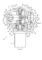
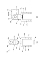
- FIG. 1 is a sectional view showing a speed change operating mechanism 10 according to a first embodiment of the present invention.
- the shift operation mechanism 10 is provided in a vehicle such as a truck or a bus having a mechanical automatic transmission (hereinafter referred to as a “transmission”) with automatic clutch operation, and is operated according to a manual operation by a driver or an automatic shift.
- a transmission mechanical automatic transmission
- This is a mechanism for performing a shifting operation of the transmission according to the control of the program.
- a description will be given of a speed change operating mechanism 10 that operates a transmission having five forward speeds and one reverse speed.
- the speed change operation mechanism 10 includes a box case 11, a motor 12, a ball screw 13, a main lever 14, a clutch 16, a select lever 17, a shaft 18, a select position sensor 21, and a shift position sensor 22.
- the motor 12 uses a battery provided in the vehicle as a drive source, and is driven and controlled by a drive control signal input from a computer provided in the vehicle, and is attached to the side surface of the box case 11 with a plurality of bolts 25 via an adapter 24.
- Reference numeral 12 a is a rotation shaft of the motor 12.
- the ball screw 13 has one end attached to the rotating shaft 12a of the motor 12 and the other end supported by a bearing 27 provided on the box case 11 and a plurality of balls (not shown) on the screw shaft 31. And a nut 33 coupled thereto. Since a thrust load is generated on the screw shaft 31 during its rotation, in order to receive this thrust load, a bearing is provided between the inner surface 24a of the adapter 24 and one end flange portion 31a provided at one end of the screw shaft 31 and a bearing. Thrust bearings 28 and 29 are provided between the inner side surface 27a of 27 and the other end flange portion 31b provided at the other end of the screw shaft 31, respectively.
- the main lever 14 has one end 14 a engaged with the nut 33 of the ball screw 13 and the other end 14 b connected to the shaft 18.
- the nut 33 is provided with a pair of projecting pins 33a projecting on both sides (the front and back sides of the paper), and a pair of notch portions 14e provided at one end of the main lever 14 are engaged with the pair of projecting pins 33a. is doing.
- the other end portion 14b of the main lever 14 includes two other end arm portions 14d and 14d formed in a bifurcated shape.
- the clutch 16 is an electromagnetic clutch, and is fitted to the screw shaft 31, the stator 36 attached to the adapter 24, the rotor 37 that is rotatably fitted to the stator 36 and is integrally attached to the screw shaft 31. And an armature 38 disposed so as to be adjacent to the rotor 37.
- the stator 36 includes a core 41 attached to the adapter 24 and a coil 42 provided in the core 41.
- the armature 38 can rotate relative to the rotor 37 when the coil 42 of the stator 36 is not energized.
- the armature 38 is attracted to the rotor 37 by the excited core 41 and rotates together with the screw shaft 31 and the rotor 37.
- the select lever 17 has one end portion 17a attached to one side surface 38a of the armature 38 and extending along the screw shaft 31 to pass through the inside of the main lever 14, and to the axial extension portion 17b.
- the shaft right-angled portion 17c that is bent so as to be orthogonal to the screw shaft 31 and is rotatably fitted to the screw shaft 31 is integrally formed. Accordingly, the select lever 17 rotates together with the armature 38.
- the main lever 14 with which the armature 38 is engaged also rotates (swings).
- the shaft 18 is coupled to the main lever 14 via a coupling pin 45.
- the shaft 18 can move in the axial direction with respect to the box case 11 (moves in the front and back direction on the paper surface).
- the nut 33 moves in the axial direction, the shaft 18 can rotate around the axis (rotate around the axis extending in the front and back direction of the paper surface).
- the select position sensor 21 is a sensor that detects the swing angle of the select lever 17 around the screw shaft 31 via the armature 38, and is attached to the lower portion of the box case 11.
- the select position sensor 21 includes a sensor main body 52 attached to the box case 11 with a plurality of bolts 51, a select sensor arm 54 attached to a rotating shaft 53 extending from the sensor main body 52, and an end of the select sensor arm 54. And a select sensor detector 56 inserted into an engaging groove 38 b provided in the armature 38.
- the select sensor detector 56 rotates the rotation shaft 53 of the sensor main body 52 via the select sensor arm 54 accordingly.
- a corresponding rotation angle signal is output from the sensor main body 52 to the computer of the vehicle, and the computer determines the selection operation state of the transmission.
- the shift position sensor 22 includes a sensor main body 62 attached to the box case 11 with a plurality of bolts 61, a shift sensor arm 64 attached to a rotation shaft 63 extending from the sensor main body 62, and an end of the shift sensor arm 64. And a shift sensor detector 66 inserted into a guide groove 65a of a guide member 65 provided at a lower portion of the nut 33.
- the box case 11 has a shaft insertion portion 11a through which the shaft 18 is passed.
- a shaft insertion hole 11b is formed in the shaft insertion portion 11a, and a shaft 18 is inserted into the shaft insertion hole 11b so as to be movable in the axial direction and rotatable about the axis.
- the main lever 14 is passed between the nut 33 of the ball screw 13 and the one end 18 a of the shaft 18.
- the one end portion 14 a of the main lever 14 includes a pair of one end arm portions 14 c and 14 c formed in a bifurcated shape, and the notch portions 14 e of the one end arm portions 14 c and 14 c swing on the pair of projecting pins 33 a of the nut 33, respectively. It is movably engaged.
- a select lever 17 is inserted between the pair of one end arm portions 14c and 14c so as to be movable relative to the one end arm portions 14c and 14c with almost no gap.
- the other end portion 14b of the main lever 14 has a pair of other end arm portions 14d with pin insertion holes 14f, and the shaft 18 has one end portion 18a with a pin insertion hole 18b.
- the connecting pin 45 is inserted into 14f and 18b, and the main lever 14 and the shaft 18 are connected. Further, a through pin 46 passes through the shaft 18 and the connecting pin 45 so as to be orthogonal to the axial directions of the shaft 18 and the connecting pin 45. As a result, the axial movement and the perpendicular movement of the connecting pin 45 with respect to the pin insertion hole 18b of the shaft 18 are restricted.
- the shaft 18 has a shift lever member 71 attached to the other end 18c.
- the transmission lever member 71 is disposed in the transmission lever space 11E formed in the shaft insertion portion 11a, and is provided so as to protrude from the outer peripheral surface of the cylindrical portion 71a and the cylindrical portion 71a that is fitted to the other end portion 18c of the shaft 18.
- a shift lever 71b is selectively engaged with each part of a shift lever input portion of a transmission (not shown), and a shift position (for example, one of five forward speeds and one reverse speed) is determined by axial movement and rotation of the shaft 18. Can be selected.
- the shift position sensor 22 is a sensor that detects the amount of movement of the nut 33 along the screw shaft 31 via the guide member 65, and is attached to the lower portion of the box case 11.
- Reference numeral 11 c denotes a window portion opened in the lower portion of the box case 11 in order to insert the shift sensor detector 66 of the shift position sensor 22 from the outside to the inside of the box case 11.
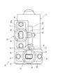
- FIG. 3 is a bottom view showing the speed change operation mechanism 10 and is a view taken in the direction of arrow III in FIG.
- the select position sensor 21 includes a rectangular flange 52a in the sensor body 52, a bolt 51 is inserted into a bolt insertion hole (not shown) provided in the flange 52a, and the tip of the bolt 51 is a screw hole on the box case 11 side.
- the select position sensor 21 is attached to the box case 11 by screwing. As the select lever 17 (see FIG. 1) swings, the select sensor arm 54 of the select position sensor 21 swings along with the select sensor detector 56 in the direction of arrow A in the figure.
- Reference numeral 57 denotes an output connector provided in the sensor main body 52 for connecting a lead wire for taking out the output of the sensor main body 52 to the outside.
- the shift position sensor 22 includes a rectangular flange 62a in the sensor body 62, a bolt 61 is inserted into a bolt insertion hole (not shown) provided in the flange 62a, and the tip of the bolt 61 is a screw hole on the box case 11 side.
- the shift position sensor 22 is attached to the box case 11 by screwing.
- the shift sensor arm 64 of the shift position sensor 22 swings in the direction of arrow B in the drawing together with the shift sensor detector 66 as the nut 33 (see FIG. 1) moves.
- the rotation shaft 63 of the sensor body 62 rotates, and an electrical signal corresponding to the amount of movement of the nut 33 is output from the sensor body 62.
- Reference numeral 11d denotes a window portion opened at the bottom of the box case 11 in order to insert the select sensor detector 56 of the select position sensor 21 from the outside to the inside of the box case 11, and 77 denotes the output of the sensor body 62 to the outside. This is an output connector provided in the sensor body 62 for connecting the lead wire to be taken out.
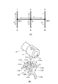
- FIG. 4A and 4B are explanatory views showing an example of a shift pattern of a shift operation by the shift operation mechanism 10,
- FIG. 4A is a diagram showing the shift pattern
- FIG. 4B is a diagram showing a shift lever member 71 of the shaft 18 and a shift. It is a figure which shows the lever input part 170.
- FIG. 4 (A) a shift pattern having a shift position of five forward speeds and one reverse speed includes a first shift direction S that shifts up or down between the first speed and the second speed, the third speed, A second shift direction T that shifts up or down between the fourth speed and a third shift direction U that shifts between the fifth speed and reverse R (reverse) are provided.
- the shift pattern includes a neutral position N located between the third speed and the fourth speed and a first select position SE1 located between the first speed and the second speed, and between the neutral position N and the fifth speed and reverse.
- a select direction V for moving between the second select position SE2 and the second select position SE2 is provided.
- the neutral position N is an initial position of the shift position.
- the shift lever input unit 170 includes rods 171R, 172R, and 173R arranged in parallel, and shift forks 171F, 172F, and 173F that are movably supported by the rods 171R, 172R, and 173R, respectively.
- the shift forks 171F, 172F, and 173F are provided with concave engagement portions 171a, 172a, and 173a at one end and a fork main body portion 173b (only the fork main body portion 173b of the shift fork 173F is shown) at the other end.
- the shift lever 71b is selectively engaged with the engaging portions 171a, 172a, and 173a.
- the speed change lever 71b is separated from the engaging portions 171a, 172a, 173a for convenience.
- the fork main body 171b moves a sleeve (not shown) to mesh a predetermined transmission gear pair of the transmission.
- the speed change lever 71b can be selectively engaged with any of the engaging portions 171a, 172a, 173a of the shift forks 171F, 172F, 173F, Further, by rotating the shaft 18 in the arrow X direction, any one of the shift forks 171F, 172F, and 173F is moved in the shift direction by the shift lever 71b engaged with any of the engaging portions 171a, 172a, and 173a. It is possible to shift to 1st speed, 3rd speed, 5th speed side, 2nd speed, 4th speed, reverse R side.
- the structure of the shift lever input unit 170 is not limited to the above.
- FIG. 5 is an operation diagram showing a shift operation of the speed change operation mechanism 10
- FIG. 5A is an operation diagram showing a state in which the screw shaft 31 is rotated in one direction with the clutch 16 turned off.
- (B) is an operational view showing a state in which the screw shaft 31 is rotated in the other direction with the clutch 16 turned off.
- FIG. 5A in a state where the energization to the coil 42 of the stator 36 is stopped and the clutch 16 is turned off, the stator 36 is not energized. 38 is not restrained.
- the coil 42 of the stator 36 is energized and the motor is operated with the clutch 16 turned off to move the screw shaft 31 of the ball screw 13 in the direction of arrow F.
- the rotor 37 rotates with the screw shaft 31, and the armature 38 and the select lever 17 are stationary.
- the nut 33 moves away from the motor.
- the main lever 14 rotates about the shaft 18 as indicated by an arrow H.
- the shift lever 71b also swings in the H direction.
- the second speed from the first select position SE1 the fourth speed from the neutral position N, or the first speed. 2. Shift from the select position SE2 to reverse.
- FIG. 6 is an operation diagram showing the selection operation of the speed change operation mechanism 10.
- FIG. 6A shows a state in which the screw shaft 31 is rotated in one direction with the clutch 16 (see FIG. 1) turned on.
- FIG. 6B is an operation diagram illustrating a state in which the screw shaft 31 is rotated in the other direction while the clutch 16 is turned on.
- the coil 36 of the stator 36 is energized to excite the stator 36 and the armature 38 is attracted to the rotor 37 and the clutch 16 is turned on (connected)
- the armature 38 is restrained with respect to the rotor 37.
- the motor is operated and the screw shaft 31 of the ball screw 13 is rotated in the direction of the arrow J as shown in FIG.
- the select lever 17 is integrated with the screw shaft 13.
- the main lever 14 is also rotated in the direction of arrow J integrally with the select lever 17.
- the shaft 18 moves as indicated by the white arrow K
- the speed change lever 71b moves in the arrow L direction. Therefore, in FIGS. 4 (A) and 4 (B), for example, in the select direction, the neutral position N To the first select position SE1 on the 1st to 2nd speed side.
- the screw shaft 31 and the select lever 17 rotate integrally, the screw shaft 31 and the select lever 17 and the nut 33 rotate integrally, so that the screw shaft 31 and the nut 33 rotate relative to each other. do not do.
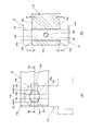
- FIG. 7 is an explanatory view showing one end portion 18a of the shaft 18 connected to the main lever 14.
- FIG. 7A is a side view of the one end portion 18a of the shaft 18, and
- FIG. 7B is FIG. 7B-7B is a cross-sectional view taken along line 7B-7B.
- the shaft 18 is provided with a pin insertion hole 18b having an elliptical cross section into which a columnar connecting pin 45 is inserted at one end 18a.
- the pin insertion hole 18 b is formed such that the elliptical long axis extends in the axial direction of the shaft 18.
- Reference numerals 18f and 18f are pin through holes opened in the shaft 18 for rotatably inserting the through pins 46 into the shaft 18, and 45a is a pin through hole formed in the connecting pin 45 for press-fitting the through pins 46.
- a hole CL is a one-side clearance between the pin insertion hole 18b and the connecting pin 45 in the major axis direction of the pin insertion hole 18b.
- the inclined surfaces 18 d and 18 e of the shaft 18 are formed in a plane and are inclined with respect to the outer peripheral surface of the shaft 18 by an angle ⁇ .
- the inclined surfaces 18d and 18e when the connecting pin 45 is inclined in the pin insertion hole 18b, the other end arm portions 14d and 14d of the main lever 14 can also be inclined along the inclined surfaces 18d and 18e.
- the connecting pin 45 is tilted in the pin insertion hole 18b with the through pin 46 as the center without moving in the axial direction and the direction perpendicular to the axis (long axis direction of the pin insertion hole 18b).
- FIG. 8 is an operation diagram showing an operation when the shift operation mechanism 10 performs the shift operation and the select operation simultaneously.
- FIG. 8A is a diagram viewed from the axial direction of the shaft 18, and FIG. ) Is a view seen from the axial direction of the screw shaft 31.
- the pin insertion hole 18b of the shaft 18 of the present embodiment is long even when the main lever 14 is swung to the maximum in the shift direction and the select direction.
- inclined surfaces 18d and 18e see FIGS.
- the shaft 18 is rotated in the shift direction by the main lever 14 as a lever, and the main lever 14, in the speed change operation mechanism 10 that moves the shaft 18 in the select direction, the screw shaft 31 that constitutes the ball screw 13, the motor 12 that rotates the screw shaft 31, the nut 33 that is screwed to the screw shaft 31, and the screw shaft 31 and a select lever 17 that is integrated with the screw shaft 31 when the clutch 16 is turned on and is unconstrained with respect to the screw shaft 31 when the clutch 16 is turned off. While engaging with the nut 33, the other end was engaged or connected with the shaft 18, and the select lever 17 was engaged with the main lever 14.
- the shift operation and the select operation of the transmission can be performed by one motor 12, and the transmission operation mechanism 10 can be reduced in size and weight, the power consumption can be reduced, the components and operating parts can be simplified and the number of points can be reduced, and Cost reduction can be achieved.
- the clutch 16 is disposed in the vicinity of the motor 12, the wiring connected to the motor 12 and the clutch 16 can be easily combined, and the length of the wiring can be shortened. It is possible to reduce the number of parts and the like to fix the cost and the number of assembly steps.
- the shift position sensor 22 that detects the movement distance of the nut 33 is provided, the shift position sensor 22 detects the movement distance of the nut 33, and the shaft 18 that swings with the movement of the nut 33 swings in the shift direction.
- the shift operation state can be obtained from the angle.
- the select position sensor 21 for detecting the swing angle of the select lever 17 the swing angle of the select lever 17 is detected by the select position sensor 21, and the shaft 18 moved along with the swing of the select lever is detected.
- the select operation state can be obtained from the movement amount in the select direction.
- FIG. 9 is an explanatory view showing one end 83a of the shaft 83 of the second embodiment
- FIG. 9 (A) is a side view of the one end 83a of the shaft 83
- FIG. 9 (B) is FIG. 9 (A).
- FIG. 9B is a sectional view taken along line 9B-9B.
- the shaft 83 has a pin insertion hole 83b in which the connecting pin 45 is inserted into one end 83a, and the cross section is mostly elliptical and tapered. Is opened.
- the pin insertion hole 83b includes two elliptical tapered holes 83c and 83c having the same shape and an elliptical cross section, and a portion where the elliptical tapered holes 83c and 83c are in contact (that is, an inner diameter portion 83d including the axis 83e of the shaft 83) is formed.
- the circular cross section is formed into a tapered shape having an elliptical cross section that gradually expands toward the outer peripheral surface. The major axis of the ellipse extends in the axial direction of the shaft 18.
- FIG. 10 is an explanatory view showing the main lever 86 according to the third embodiment.
- FIG. 10 (A) is an exploded view of the main lever 86
- FIG. 10 (B) is a state where the main lever 86 is assembled to the shaft 84.
- FIG. 10A and 10B the main lever 86 includes one end side arm member 87 engaged with the nut 33 (see FIG. 1) side and the shaft 84 (see FIG. 10B) side.
- the other end side arm member 88, the one end side arm member 87, and the other end side arm member 88 are joined so that the other end side arm member 88 is not detached from the one end side arm member 87.
- a retaining ring 89 is provided.
- the one end side arm member 87 is integrally formed with a flat base 87a and a pair of one end arms 87b, 87b extending from both ends of the base 87a so as to be perpendicular to the base 87a.
- the base 87a has a through hole 87c in the center thereof.
- the one end arm portion 87b is formed with a notch portion 14e, and the notch portion 14e engages with the protruding pin 33a (see FIG. 1) of the nut 33 (see FIG. 1).
- the other end side arm member 88 includes a base portion 88a, other end arm portions 88b and 88b extending in parallel from both ends of the base portion 88a, and a connecting shaft 88c extending from the center of the base portion 88a to the opposite side of the other end arm portions 88b and 88b. It consists of.
- the other end arms 88b and 88b are each provided with a pin insertion hole 88d having a circular cross section.
- the connecting shaft 88c has an annular groove 88e formed in the vicinity of the tip thereof, and is inserted into the through hole 87c of the one end side arm member 87. After the insertion, a retaining ring 89 is attached to the annular groove 88e.
- the end arm member 88 is prevented from coming off from the one end side arm member 87. Since a minute gap is formed between the through hole 87c and the connecting shaft 88c, the connecting shaft 88c is rotatably coupled to the through hole 87c. That is, the other end side arm member 88 is rotatably attached to the one end side arm member 87.
- the connecting pin 90 is inserted into the pin insertion hole 88 d of the other end side arm member 88 and the pin insertion hole 84 b formed in the shaft 84.
- the pin insertion hole 84b and the pin insertion hole 88d are straight round holes.
- the connecting pin 90 is a straight pin with a circular cross section.
- FIG. 11 is a cross-sectional view showing a speed change operation mechanism 100 according to the fourth embodiment.
- the speed change operation mechanism 100 includes a box case 101, a motor 102, a ball screw 103, a main lever 14, a clutch 106, a select lever 107, a shaft 18, a select position sensor 121, and a shift position sensor 122.
- the motor 102 is driven and controlled by a drive control signal input from a computer provided in the vehicle.
- the motor 102 is provided with a plurality of bolts (not shown) on the side surface of the box case 101 via an adapter 124. Installed.
- One end of the ball screw 103 is attached to the rotating shaft 102 a of the motor 102 via a joint 104 and is rotatably supported by a bearing 105 provided in the box case 101, and the other end is provided in a bearing portion provided in the box case 101.
- the screw shaft 131 is supported by 101a, and the nut 33 is coupled to the screw shaft 131 via a plurality of balls (not shown). Since a thrust load is generated on the screw shaft 131 when the screw shaft 131 rotates, the bearing 105 receives the thrust load on one end side of the screw shaft 131, and the bearing portion 101 a and the screw shaft 131 on the other end side of the screw shaft 131. Is received by a thrust bearing 129 provided between the flange portion 128 and the flange portion 128.
- the clutch 106 is an electromagnetic clutch, and engages with the stator 36 attached to the box case 101, the rotor 137 that is rotatably fitted to the stator 36 and integrally attached to the screw shaft 131, and the screw shaft 131. And an armature 138 disposed adjacent to the rotor 137.
- the stator 36 includes a core 41 attached to the box case 101 and a coil 42.
- the select lever 107 is an L-shaped member attached to the armature 138, and includes a base portion 107a attached to one side surface 138a of the armature 138 and a main lever extending from one end of the base portion 107a along the screw shaft 131. 14 and an axially extending portion 107b passing through the inside of 14 are integrally formed.
- the rotor 137 rotates together with the screw shaft 131 when energization to the coil 42 is stopped, and when the coil 42 is energized, the armature 138 is attracted to the rotor 137 by the excited core 41, and the armature
- the select lever 17 fixed to 138 rotates integrally with the screw shaft 131.
- the shaft 18 can rotate about the axis (rotation about an axis extending in the front and back direction of the paper surface) with respect to the box case 101 by the main lever 14 swinging about the screw shaft 131, As the nut 33 moves in the axial direction on the screw shaft 131, the box case 101 is supported so as to be capable of rotating about the axis (rotating about the axis extending in the front and back direction of the paper surface).
- the select position sensor 121 is a sensor that detects a rotation angle around the screw shaft 131 of the select lever 107 and is attached to a side portion of the box case 101.
- the select position sensor 121 includes a sensor main body 52, a select sensor arm 54, and a select sensor detector 156 that is attached to an end portion of the select sensor arm 54 and is inserted into an engaging portion 107 c provided on the select lever 107. Prepare.
- the shift position sensor 122 is a sensor that detects the amount of movement of the nut 33 along the screw shaft 131 via the guide member 65, and is attached to the lower portion of the box case 101.
- the shift position sensor 122 includes a sensor body 62 attached to the box case 101 with a plurality of bolts 61, a rotating shaft 63, a shift sensor arm 158 having one end attached to the rotating shaft 63, and a shift sensor arm 158.
- a shift sensor detector 166 provided at the other end, and the shift sensor detector 166 is inserted into the guide groove 65 a of the guide member 65.
Landscapes
- Engineering & Computer Science (AREA)
- General Engineering & Computer Science (AREA)
- Mechanical Engineering (AREA)
- Gear-Shifting Mechanisms (AREA)
Abstract
Description
本発明の目的は、小型・軽量化、消費電力低減、構成部品の簡素化と点数削減、及び低コスト化を図ることが可能な変速操作機構を提供することにある。
上述した課題を解決するため、本発明は、レバーによりシャフトをシフト方向に回動させると共に、前記レバーにより前記シャフトをセレクト方向に移動させる変速操作機構において、ボールねじを構成するねじ軸と、前記ねじ軸を回転させるモータと、前記ねじ軸に螺合するナットと、前記ねじ軸上に配置されたクラッチと、前記クラッチのオンにより前記ねじ軸と一体化し、前記クラッチのオフにより前記ねじ軸に対し拘束が解かれるセレクトレバーと、を備え、前記レバーの一端を前記ナットに係合すると共に、他端を前記シャフトに係合し、前記セレクトレバーを前記レバーに係合させた、ことを特徴とする。
また、上記構成において、前記セレクトレバーの揺動角度を検知するセレクトポジションセンサを備えても良い。この構成によれば、セレクトポジションセンサによりセレクトレバーの揺動角度を検知して、セレクト動作状態を求めることができる。
<第1実施形態>
図1は、本発明の第1実施形態の変速操作機構10を示す断面図である。
変速操作機構10は、クラッチ操作を自動化した機械式自動変速機(以下、「変速機」と記す。)を有するトラック、バス等の車両に設けられ、運転者の手動操作に従って、或いは、自動変速プログラムの制御に従って変速機の変速操作を行う機構である。本実施形態では、前進5段、後進1段の変速機を操作する変速操作機構10について説明する。
ボックスケース11内には、上記ボールねじ13、メインレバー14、クラッチ16、セレクトレバー17、シャフト18が収容されている。
モータ12は、車両に備えるバッテリを駆動源とし、また、車両に備えるコンピュータから入力される駆動制御信号により駆動制御され、ボックスケース11の側面にアダプタ24を介して複数のボルト25で取付けられている。なお、符号12aはモータ12の回転軸である。
ボールねじ13は、一端がモータ12の回転軸12aに取付けられるとともに他端がボックスケース11に設けられた軸受27に支持されたねじ軸31と、ねじ軸31に複数のボール(不図示)を介して結合されたナット33とから構成されている。ねじ軸31には、その回転時にスラスト荷重が発生するため、このスラスト荷重を受けるために、アダプタ24の内側面24aとねじ軸31の一端に設けられた一端フランジ部31aとの間、及び軸受27の内側面27aとねじ軸31の他端に設けられた他端フランジ部31bとの間に、それぞれスラスト軸受28,29が設けられている。
クラッチ16は、電磁クラッチであり、アダプタ24に取付けられたステータ36と、ステータ36に回転可能に嵌合するとともにねじ軸31に一体的に取付けられたロータ37と、ねじ軸31に嵌合するとともにロータ37に隣接するように配置されたアーマチュア38とを備える。
セレクトレバー17は、一端部17aがアーマチュア38の一側面38aに取付けられるとともにねじ軸31に沿って延びてメインレバー14の内側を通る軸方向延出部17bと、軸方向延出部17bに対してねじ軸31に直交するように屈曲するとともにねじ軸31に回動可能に嵌合する軸直角部17cとが一体成形されたものである。従って、セレクトレバー17は、アーマチュア38と共に回動する。アーマチュア38が回動すると、アーマチュア38が係合するメインレバー14も回動(揺動)する。
セレクトポジションセンサ21は、アーマチュア38を介してセレクトレバー17のねじ軸31回りの揺動角度を検出するセンサであり、ボックスケース11の下部に取付けられている。
セレクトレバー17及びアーマチュア38が揺動すると、それに伴ってセレクトセンサ検出子56がセレクトセンサアーム54を介してセンサ本体52の回動軸53を回動させるため、回動軸53の回動角度に応じた回動角度信号がセンサ本体52から車両のコンピュータに出力され、コンピュータでは、変速機のセレクト動作状態が求められる。
ボックスケース11は、その上部にシャフト18が通されるシャフト挿通部11aが形成されている。シャフト挿通部11aにはシャフト挿通穴11bが形成され、シャフト挿通穴11bにシャフト18が軸方向に移動可能及び軸回りに回動可能に挿入されている。
ボールねじ13のナット33と、シャフト18の一端部18aとには、メインレバー14が渡されている。
メインレバー14の一端部14aは、二股状に形成された一対の一端アーム部14c,14cを備え、一端アーム部14c,14cの切欠き部14eが、ナット33の一対の突出ピン33aにそれぞれ揺動可能に係合している。一対の一端アーム部14c,14c間にはセレクトレバー17が、一端アーム部14c,14cに対してほぼ隙間なく且つ相対移動可能に挿入されている。
シャフト18は、他端部18cに変速レバー部材71が取付けられている。変速レバー部材71は、シャフト挿通部11aに形成された変速レバー空間11Eに配置され、シャフト18の他端部18cに嵌合する筒部71aと、筒部71aの外周面に突出するように設けられた変速レバー71bとを備える。
変速レバー71bは、変速機(不図示)の変速レバー入力部の各部に選択的に係合され、シャフト18の軸方向移動及び回動による変速ポジション(例えば、前進5段及び後進1段のいずれか)の選択が可能になる。
シフトポジションセンサ22は、ガイド部材65を介してナット33のねじ軸31に沿った移動量を検出するセンサであり、ボックスケース11の下部に取付けられている。なお、符号11cはシフトポジションセンサ22のシフトセンサ検出子66をボックスケース11の外側から内側へ挿入するためにボックスケース11の下部に開けられた窓部である。
セレクトポジションセンサ21は、センサ本体52に矩形のフランジ52aを備え、フランジ52aに設けられたボルト挿通穴(不図示)にボルト51が挿入され、ボルト51の先端がボックスケース11側のねじ穴にねじ結合されてボックスケース11にセレクトポジションセンサ21が取付けられる。
セレクトポジションセンサ21のセレクトセンサアーム54は、セレクトレバー17(図1参照)の揺動に伴って、セレクトセンサ検出子56と共に図中の矢印A方向に揺動する。この結果、センサ本体52の回動軸53が回動し、セレクトレバー17の揺動角度に相当する電気信号がセンサ本体52から出力される。なお、符号57はセンサ本体52の出力を外部に取り出す導線を接続するためにセンサ本体52に設けられた出力コネクタである。
シフトポジションセンサ22のシフトセンサアーム64は、ナット33(図1参照)の移動に伴って、シフトセンサ検出子66と共に図中の矢印B方向に揺動する。この結果、センサ本体62の回動軸63が回動し、ナット33の移動量に相当する電気信号がセンサ本体62から出力される。なお、符号11dはセレクトポジションセンサ21のセレクトセンサ検出子56をボックスケース11の外側から内側へ挿入するためにボックスケース11の下部に開けられた窓部、77はセンサ本体62の出力を外部に取り出す導線を接続するためにセンサ本体62に設けられた出力コネクタである。
図4(A)に示すように、前進5段、後進1段の変速ポジションを有する変速パターンには、1速、2速間をシフトアップ又はシフトダウンする第1シフト方向Sと、3速、4速間をシフトアップ又はシフトダウンする第2シフト方向Tと、5速、リバースR(後進)間をシフトする第3シフト方向Uとが設けられている。また、変速パターンには、3速、4速間に位置するニュートラル位置Nと、1速、2速間に位置する第1セレクト位置SE1との間、及びニュートラル位置Nと、5速、リバース間に位置する第2セレクト位置SE2との間を移動させるセレクト方向Vが設けられている。
ニュートラル位置Nは、変速ポジションの初期位置である。
変速レバー入力部170は、平行に配置されたロッド171R,172R,173Rと、これらのロッド171R,172R,173Rにそれぞれ移動可能に支持されたシフトフォーク171F,172F,173Fとを備える。
シフトフォーク171F,172F,173Fは、一端に凹状の係合部171a,172a,173a、他端にフォーク本体部173b(シフトフォーク173Fのフォーク本体部173bのみ図示)が設けられている。
係合部171a,172a,173aには、変速レバー71bが選択的に係合される。図4(B)では便宜上係合部171a,172a,173aから変速レバー71bを離している。
フォーク本体部171bは、スリーブ(不図示)を移動させて変速機の所定の変速ギア対を噛み合わせる。
図5は、変速操作機構10のシフト動作を示す作用図であり、図5(A)はクラッチ16をオフにした状態でねじ軸31を一方向に回転させた状態を示す作用図、図5(B)はクラッチ16をオフにした状態でねじ軸31を他方向に回転させた状態を示す作用図である。
図5(A)に示すように、ステータ36のコイル42への通電を停止して、クラッチ16をオフにした状態では、ステータ36が励磁されていないため、ステータ36に対してロータ37及びアーマチュア38が拘束されない。この状態で、モータを作動させてボールねじ13のねじ軸31を矢印C方向に回転させた場合には、ロータ37がねじ軸31と共に回転し、アーマチュア38及びセレクトレバー17は、静止した状態にある。
ナット33は、矢印Dで示すように、モータに近づく側へ移動する。これに伴って、メインレバー14は、矢印Eで示すように、シャフト18を中心にして回動する。この結果、変速レバー71b(図2参照)もE方向に揺動し、図4(A),(B)において、第1セレクト位置SE1から1速、ニュートラル位置Nから3速、あるいは第2セレクト位置SE2から5速に変速される。
ナット33は、矢印Gで示すように、モータから離れる側へ移動する。これに伴って、メインレバー14は、矢印Hで示すように、シャフト18を中心にして回動する。この結果、変速レバー71b(図2参照)もH方向に揺動し、図4(A),(B)において、例えば、第1セレクト位置SE1から2速、ニュートラル位置Nから4速、あるいは第2セレクト位置SE2からリバースに変速される。
図1において、ステータ36のコイル42に通電させてステータ36を励磁させ、ロータ37にアーマチュア38を吸引させてクラッチ16をオン(接続)にした状態では、ロータ37に対してアーマチュア38が拘束される。この状態で、モータを作動させてボールねじ13のねじ軸31を、図6(A)に示すように、矢印J方向に回動させた場合には、ねじ軸13と共にセレクトレバー17が一体的に回動し、メインレバー14もセレクトレバー17と一体的に矢印J方向に回動する。この結果、シャフト18が、白抜き矢印Kで示すように移動し、変速レバー71bが矢印L方向に移動するので、図4(A),(B)において、例えば、セレクト方向で、ニュートラル位置Nから1速-2速側の第1セレクト位置SE1へ移動する。
このとき、ねじ軸31とセレクトレバー17とが一体的に回動するので、ねじ軸31及びセレクトレバー17とナット33とが一体的に回動するため、ねじ軸31とナット33とは相対回転しない。
図7(A)に示すように、シャフト18は、その一端部18aに、円柱状の連結ピン45が挿入される断面楕円形のピン挿通穴18bが開けられている。ピン挿通穴18bは、楕円形の長軸がシャフト18の軸方向に延びるように形成されている。ピン挿通穴18bの長軸方向の縁部には、その縁部からシャフト18の軸方向に離れるにつれて次第にシャフト18の径方向中央側に配置される傾斜面18d,18eが形成されている。なお、符号18f,18fはシャフト18に貫通ピン46を回転可能に挿入するためにシャフト18に開けられたピン貫通穴、45aは貫通ピン46を圧入するために連結ピン45に開けられたピン貫通穴、CLはピン挿通穴18bの長軸方向におけるピン挿通穴18bと連結ピン45との片側クリアランスである。
図7(B)に示すように、シャフト18の傾斜面18d,18eは、平面に形成され、シャフト18の外周面に対して角度θだけ傾いている。この傾斜面18d,18eによって、連結ピン45がピン挿通穴18b内で傾いたときに、メインレバー14の他端アーム部14d,14dも傾斜面18d,18eに沿うように傾くことが可能になる。この時、連結ピン45は、その軸方向及び軸直角方向(ピン挿通穴18bの長軸方向)にほとんど移動することなしに貫通ピン46を中心にしてピン挿通穴18b内で傾く。
図8(A)及び図8(B)に示すように、メインレバー14を、シフト方向及びセレクト方向のそれぞれに最大に揺動させる場合でも、本実施形態のシャフト18のピン挿通穴18bを長穴断面に形成するとともにシャフト18のピン挿通穴18bの縁部に傾斜面18d,18e(図7(A),(B)参照)を設けることで、ナット33とメインレバー14との連結部、及びメインレバー14とシャフト18との連結部では無理なくスムーズに揺動を行わせることができる。
即ち、図5及び図6に示したような、シフト動作のみ、又はセレクト動作のみを行わせた場合のメインレバー14に対して、図8(A)及び図8(B)において、メインレバー14に生じる傾きの変化を、長穴断面としたピン挿通穴18b内で連結ピン45が傾き、また、傾斜面18d,18eに沿ってメインレバー14の他端アーム部14d,14dが傾くことにより吸収することができる。
また、ナット33の移動距離を検知するシフトポジションセンサ22を備えるので、シフトポジションセンサ22によりナット33の移動距離を検知し、ナット33の移動に伴って揺動したシャフト18のシフト方向の揺動角度から、シフト動作状態を求めることができる。
また、セレクトレバー17の揺動角度を検知するセレクトポジションセンサ21を備えることで、セレクトポジションセンサ21によりセレクトレバー17の揺動角度を検知し、セレクトレバーの揺動に伴って移動したシャフト18のセレクト方向の移動量から、セレクト動作状態を求めることができる。
図9は、第2実施形態のシャフト83の一端部83aを示す説明図であり、図9(A)はシャフト83の一端部83aの側面図、図9(B)は図9(A)の9B-9B線断面図である。図7(A),(B)に示した第1実施形態と同一構成については同一符号を付け、詳細説明は省略する。
図9(A),(B)に示すように、シャフト83は、その一端部83aに、連結ピン45が挿入される、断面の大部分が楕円形で且つテーパ穴とされたピン挿通穴83bが開けられている。
ピン挿通穴83bは、同一形状で断面楕円形とされた2つの楕円テーパ穴83c,83cを含み、楕円テーパ穴83c,83cの接する部分(即ち、シャフト83の軸線83eを含む内径部83d)は、円形断面に形成され、その円形断面が、外周面に行くにつれて次第に広がって断面楕円形のテーパ形状に形成されている。楕円形の長軸はシャフト18の軸方向に延びている。ピン挿通穴83bの長軸方向の縁部には、その縁部から離れるにつれて次第にシャフト83の径方向中央側に配置された傾斜面18d,18eが形成されている。
上記したように、ピン挿通穴83bは、円形断面の内径部83dを含むため、この内径部83dによって、ピン挿通穴83bに挿入された連結ピン45はシャフト83の軸方向への移動が規制される。従って、図7(A),(B)に示した貫通ピン46は不要である。
図10は、第3実施形態のメインレバー86を示す説明図であり、図10(A)はメインレバー86の分解図、図10(B)はメインレバー86をシャフト84に組付けた状態を示す側面図である。
図10(A),(B)に示すように、メインレバー86は、ナット33(図1参照)側に係合される一端側アーム部材87と、シャフト84(図10(B)参照)側に連結される他端側アーム部材88と、一端側アーム部材87と他端側アーム部材88とを結合したときに、一端側アーム部材87から他端側アーム部材88が外れないように止めておく止め輪89とからなる。
一端側アーム部材87は、平板状の基部87aと、基部87aの両端から基部87aに直角となるように延びる一対の一端アーム部87b,87bとが一体に形成されている。
基部87aは、その中央に貫通穴87cが開けられている。一端アーム部87bは、切欠き部14eが形成され、切欠き部14eがナット33(図1参照)の突出ピン33a(図1参照)と係合する。
他端アーム部88b,88bは、それぞれ断面円形のピン挿通穴88dが開けられている。連結軸88cは、その先端部の近傍に環状溝88eが形成され、一端側アーム部材87の貫通穴87cに挿入されるとともに、挿入された後に環状溝88eに止め輪89が装着されて、他端側アーム部材88の一端側アーム部材87からの抜け止めが図られる。
貫通穴87cと連結軸88cとの間には、微小な隙間が形成されているので、貫通穴87cに対して連結軸88cが回転可能に結合される。即ち、一端側アーム部材87に対して他端側アーム部材88は、回転可能に取付けられる。
他端側アーム部材88のピン挿通穴88d及びシャフト84に開けられたピン挿通穴84bには、連結ピン90が挿入される。ピン挿通穴84b及びピン挿通穴88dはストレートの丸穴である。連結ピン90は、円形断面でストレートピンである。
図11は、第4実施形態の変速操作機構100を示す断面図である。
図1に示した第1実施形態と同一構成については同一符号を付け、詳細説明は省略する。
変速操作機構100は、ボックスケース101、モータ102、ボールねじ103、メインレバー14、クラッチ106、セレクトレバー107、シャフト18、セレクトポジションセンサ121、シフトポジションセンサ122を備える。
ボックスケース101内に、上記ボールねじ103、メインレバー14、クラッチ106、セレクトレバー107、シャフト18が収容されている。
モータ102は、車両に備えるバッテリを駆動源とし、また、車両に備えるコンピュータから入力される駆動制御信号により駆動制御され、ボックスケース101の側面にアダプタ124を介して複数のボルト(不図示)で取付けられている。
ロータ137は、コイル42への通電が停止されているときには、ねじ軸131と共に回転し、コイル42に通電が行われたときには、励磁されたコア41によって、ロータ137にアーマチュア138が吸引され、アーマチュア138に固定されたセレクトレバー17がねじ軸131と一体的に回動する。
セレクトポジションセンサ121は、セレクトレバー107のねじ軸131回りの回動角度を検出するセンサであり、ボックスケース101の側部に取付けられている。
セレクトポジションセンサ121は、センサ本体52と、セレクトセンサアーム54と、セレクトセンサアーム54の端部に取付けられるとともにセレクトレバー107に設けられた係合部107cに挿入されたセレクトセンサ検出子156とを備える。
シフトポジションセンサ122は、ボックスケース101に複数のボルト61で取付けられたセンサ本体62と、回動軸63と、回転軸63に一端部が取付けられたシフトセンサアーム158と、シフトセンサアーム158の他端部に設けられたシフトセンサ検出子166とを備え、シフトセンサ検出子166がガイド部材65のガイド溝65a内に挿入されている。
12,102 モータ
13,103 ボールねじ
14,86 メインレバー(レバー)
16,106 クラッチ
17,107 セレクトレバー
18,83,84 シャフト
21,121 セレクトポジションセンサ
22,122 シフトポジションセンサ
31,131 ねじ軸
33 ナット
Claims (4)
- レバーによりシャフトをシフト方向に回動させると共に、前記レバーにより前記シャフトをセレクト方向に移動させる変速操作機構において、
ボールねじを構成するねじ軸と、前記ねじ軸を回転させるモータと、前記ねじ軸に螺合するナットと、前記ねじ軸上に配置されたクラッチと、前記クラッチのオンにより前記ねじ軸と一体化し、前記クラッチのオフにより前記ねじ軸に対し拘束が解かれるセレクトレバーと、を備え、前記レバーの一端を前記ナットに係合すると共に、他端を前記シャフトに係合し、前記セレクトレバーを前記レバーに係合させた、ことを特徴とする変速操作機構。 - 前記クラッチが前記モータに近接して配置されていることを特徴とする請求項1に記載の変速操作機構。
- 前記ナットの移動距離を検知するシフトポジションセンサを備えたことを特徴とする請求項1または2に記載の変速操作機構。
- 前記セレクトレバーの揺動角度を検知するセレクトポジションセンサを備えたことを特徴とする請求項1乃至3のいずれか一項に記載の変速操作機構。
Priority Applications (4)
| Application Number | Priority Date | Filing Date | Title |
|---|---|---|---|
| CN201580021857.4A CN106255846B (zh) | 2014-05-09 | 2015-04-22 | 变速操作机构 |
| US15/302,207 US9964190B2 (en) | 2014-05-09 | 2015-04-22 | Gear shift operation mechanism |
| KR1020167032284A KR101890599B1 (ko) | 2014-05-09 | 2015-04-22 | 변속 조작 기구 |
| EP15789426.2A EP3141780B1 (en) | 2014-05-09 | 2015-04-22 | Gear shift operation mechanism |
Applications Claiming Priority (2)
| Application Number | Priority Date | Filing Date | Title |
|---|---|---|---|
| JP2014-097491 | 2014-05-09 | ||
| JP2014097491A JP6224517B2 (ja) | 2014-05-09 | 2014-05-09 | 変速操作機構 |
Publications (1)
| Publication Number | Publication Date |
|---|---|
| WO2015170593A1 true WO2015170593A1 (ja) | 2015-11-12 |
Family
ID=54392446
Family Applications (1)
| Application Number | Title | Priority Date | Filing Date |
|---|---|---|---|
| PCT/JP2015/062256 Ceased WO2015170593A1 (ja) | 2014-05-09 | 2015-04-22 | 変速操作機構 |
Country Status (6)
| Country | Link |
|---|---|
| US (1) | US9964190B2 (ja) |
| EP (1) | EP3141780B1 (ja) |
| JP (1) | JP6224517B2 (ja) |
| KR (1) | KR101890599B1 (ja) |
| CN (1) | CN106255846B (ja) |
| WO (1) | WO2015170593A1 (ja) |
Cited By (1)
| Publication number | Priority date | Publication date | Assignee | Title |
|---|---|---|---|---|
| CN108105378A (zh) * | 2018-01-31 | 2018-06-01 | 鹰潭思巴达传动科技有限公司 | 一种dct双离合自动变速箱的电控式换挡执行机构 |
Families Citing this family (6)
| Publication number | Priority date | Publication date | Assignee | Title |
|---|---|---|---|---|
| JP6916503B2 (ja) * | 2015-10-30 | 2021-08-11 | ネット株式会社 | 遊技機 |
| JP6736215B2 (ja) * | 2016-07-01 | 2020-08-05 | ジヤトコ株式会社 | 変速機ケースにおけるカバーの支持構造 |
| JP7409601B2 (ja) * | 2018-01-05 | 2024-01-09 | 株式会社東海理化電機製作所 | シフト装置 |
| CN110657231A (zh) * | 2018-06-28 | 2020-01-07 | 上海海能汽车电子有限公司 | 一种客车变速箱的丝杆直驱选换挡结构 |
| KR20210006035A (ko) * | 2019-07-08 | 2021-01-18 | 현대자동차주식회사 | 변속기의 변속 액츄에이터 |
| CN111649123A (zh) * | 2020-06-24 | 2020-09-11 | 瑞立集团瑞安汽车零部件有限公司 | 一种amt选换挡执行机构 |
Citations (4)
| Publication number | Priority date | Publication date | Assignee | Title |
|---|---|---|---|---|
| JPH10299892A (ja) * | 1997-04-18 | 1998-11-13 | Keihin Seimitsu Kogyo Kk | パワーシフタの制御装置 |
| JP2003194215A (ja) * | 2001-12-25 | 2003-07-09 | Bosch Automotive Systems Corp | モータ駆動型変速機操作装置 |
| US20130305855A1 (en) * | 2011-01-24 | 2013-11-21 | Kenneth Skogward | Gear change actuator |
| JP2014047870A (ja) * | 2012-08-31 | 2014-03-17 | Jtekt Corp | 電動アクチュエータ |
Family Cites Families (17)
| Publication number | Priority date | Publication date | Assignee | Title |
|---|---|---|---|---|
| US2548175A (en) * | 1951-04-10 | Valve unit for hydraulically | ||
| US2489474A (en) * | 1945-08-13 | 1949-11-29 | Counter And Control Corp | Mechanism for effecting automatic repetition of predetermined numbers of events |
| US2573919A (en) * | 1946-03-08 | 1951-11-06 | Packard Motor Car Co | Transmission |
| US2706912A (en) * | 1951-03-21 | 1955-04-26 | Harriett V Baker | Double screw feed |
| US2775908A (en) * | 1952-09-19 | 1957-01-01 | Lynn T Elliott | Drive source shifting device for valve control or the like |
| US2948370A (en) * | 1956-04-04 | 1960-08-09 | Eaton Mfg Co | Synchronizing means for torque transmitting device |
| DE19527893C1 (de) * | 1995-07-29 | 1996-10-31 | Ford Werke Ag | Elektrische Schaltvorrichtung für Wechselgetriebe von Kraftfahrzeugen |
| DE10201981A1 (de) * | 2001-01-31 | 2002-08-01 | Luk Lamellen & Kupplungsbau | Verfahren zur Erkennung der Synchronposition und des Endes des Synchronisiervorgangs eines automatisierten Schaltgetriebes |
| JPWO2005057051A1 (ja) | 2003-12-11 | 2007-07-05 | 株式会社日立製作所 | 電動アクチュエータとその制御装置 |
| US7581467B2 (en) * | 2005-07-11 | 2009-09-01 | Team Industries, Inc. | Transmission |
| JP5243018B2 (ja) * | 2007-12-27 | 2013-07-24 | Ntn株式会社 | 電動リニアアクチュエータ |
| JP5440862B2 (ja) | 2009-09-01 | 2014-03-12 | 株式会社ジェイテクト | 変速装置 |
| JP5472729B2 (ja) * | 2010-02-24 | 2014-04-16 | 株式会社ジェイテクト | 変速装置 |
| JP5440861B2 (ja) * | 2010-03-24 | 2014-03-12 | 株式会社ジェイテクト | 変速機駆動装置 |
| JP2013096544A (ja) | 2011-11-04 | 2013-05-20 | Jtekt Corp | 変速駆動装置 |
| JP2013100857A (ja) * | 2011-11-08 | 2013-05-23 | Jtekt Corp | 変速駆動装置 |
| JP2013104500A (ja) | 2011-11-15 | 2013-05-30 | Jtekt Corp | 電動アクチュエータ |
-
2014
- 2014-05-09 JP JP2014097491A patent/JP6224517B2/ja active Active
-
2015
- 2015-04-22 CN CN201580021857.4A patent/CN106255846B/zh not_active Expired - Fee Related
- 2015-04-22 EP EP15789426.2A patent/EP3141780B1/en not_active Not-in-force
- 2015-04-22 US US15/302,207 patent/US9964190B2/en active Active
- 2015-04-22 WO PCT/JP2015/062256 patent/WO2015170593A1/ja not_active Ceased
- 2015-04-22 KR KR1020167032284A patent/KR101890599B1/ko not_active Expired - Fee Related
Patent Citations (4)
| Publication number | Priority date | Publication date | Assignee | Title |
|---|---|---|---|---|
| JPH10299892A (ja) * | 1997-04-18 | 1998-11-13 | Keihin Seimitsu Kogyo Kk | パワーシフタの制御装置 |
| JP2003194215A (ja) * | 2001-12-25 | 2003-07-09 | Bosch Automotive Systems Corp | モータ駆動型変速機操作装置 |
| US20130305855A1 (en) * | 2011-01-24 | 2013-11-21 | Kenneth Skogward | Gear change actuator |
| JP2014047870A (ja) * | 2012-08-31 | 2014-03-17 | Jtekt Corp | 電動アクチュエータ |
Cited By (1)
| Publication number | Priority date | Publication date | Assignee | Title |
|---|---|---|---|---|
| CN108105378A (zh) * | 2018-01-31 | 2018-06-01 | 鹰潭思巴达传动科技有限公司 | 一种dct双离合自动变速箱的电控式换挡执行机构 |
Also Published As
| Publication number | Publication date |
|---|---|
| EP3141780A4 (en) | 2018-02-28 |
| US20170045125A1 (en) | 2017-02-16 |
| KR101890599B1 (ko) | 2018-08-22 |
| JP2015215018A (ja) | 2015-12-03 |
| JP6224517B2 (ja) | 2017-11-01 |
| KR20160145761A (ko) | 2016-12-20 |
| CN106255846A (zh) | 2016-12-21 |
| CN106255846B (zh) | 2018-09-28 |
| US9964190B2 (en) | 2018-05-08 |
| EP3141780A1 (en) | 2017-03-15 |
| EP3141780B1 (en) | 2020-06-17 |
Similar Documents
| Publication | Publication Date | Title |
|---|---|---|
| JP6224517B2 (ja) | 変速操作機構 | |
| JP5487902B2 (ja) | クラッチアクチュエータ | |
| KR102402603B1 (ko) | 액츄에이터 및 이를 포함하는 차량용 변속 장치 | |
| EP2696484A2 (en) | Electric actuator | |
| EP2592307A2 (en) | Electric actuator | |
| JP2010286083A (ja) | 電動アクチュエータ | |
| JPWO2015136951A1 (ja) | トルク伝達ユニット | |
| WO2014196420A1 (ja) | 電磁アクチュエータ | |
| CN102878284A (zh) | 一种用于自动变速器的电动驻车机构 | |
| KR102239345B1 (ko) | 전자식 변속레버 장치 | |
| JP6801392B2 (ja) | シフトバイワイヤ式自動変速機のアクチュエータ | |
| WO2009119819A1 (ja) | レンジ切換え装置 | |
| JP2013029138A (ja) | ギヤ位置検出装置 | |
| JP2013100856A (ja) | 変速駆動装置 | |
| EP2589840A2 (en) | Transmission actuating device | |
| JP2009079657A (ja) | 電動リニアアクチュエータおよびその組立方法 | |
| JP5829736B2 (ja) | 電動アクチュエータ | |
| JP6156682B2 (ja) | 電動アクチュエータおよびそれを備えた変速駆動装置 | |
| JP2002317871A (ja) | 変速機用電動駆動装置 | |
| JP2006010009A (ja) | モーター駆動型変速機操作装置 | |
| KR101637513B1 (ko) | 듀얼 클러치 변속기의 구동장치 | |
| JP2016114196A (ja) | シフト機構 | |
| JP6414476B2 (ja) | 自動変速機用シフト装置 | |
| JP4535276B2 (ja) | 操舵比変更アクチュエータ | |
| KR20250129786A (ko) | 변속 액추에이터 |
Legal Events
| Date | Code | Title | Description |
|---|---|---|---|
| 121 | Ep: the epo has been informed by wipo that ep was designated in this application |
Ref document number: 15789426 Country of ref document: EP Kind code of ref document: A1 |
|
| WWE | Wipo information: entry into national phase |
Ref document number: 15302207 Country of ref document: US |
|
| WWE | Wipo information: entry into national phase |
Ref document number: IDP00201607021 Country of ref document: ID |
|
| NENP | Non-entry into the national phase |
Ref country code: DE |
|
| ENP | Entry into the national phase |
Ref document number: 20167032284 Country of ref document: KR Kind code of ref document: A |
|
| REEP | Request for entry into the european phase |
Ref document number: 2015789426 Country of ref document: EP |
|
| WWE | Wipo information: entry into national phase |
Ref document number: 2015789426 Country of ref document: EP |