WO2015170726A1 - ユーザ端末、無線基地局、無線通信方法及び無線通信システム - Google Patents
ユーザ端末、無線基地局、無線通信方法及び無線通信システム Download PDFInfo
- Publication number
- WO2015170726A1 WO2015170726A1 PCT/JP2015/063244 JP2015063244W WO2015170726A1 WO 2015170726 A1 WO2015170726 A1 WO 2015170726A1 JP 2015063244 W JP2015063244 W JP 2015063244W WO 2015170726 A1 WO2015170726 A1 WO 2015170726A1
- Authority
- WO
- WIPO (PCT)
- Prior art keywords
- base station
- transmission power
- radio base
- maximum transmission
- user terminal
- Prior art date
- Legal status (The legal status is an assumption and is not a legal conclusion. Google has not performed a legal analysis and makes no representation as to the accuracy of the status listed.)
- Ceased
Links
Images





Classifications
-
- H—ELECTRICITY
- H04—ELECTRIC COMMUNICATION TECHNIQUE
- H04W—WIRELESS COMMUNICATION NETWORKS
- H04W52/00—Power management, e.g. Transmission Power Control [TPC] or power classes
- H04W52/04—Transmission power control [TPC]
- H04W52/06—TPC algorithms
- H04W52/14—Separate analysis of uplink or downlink
- H04W52/146—Uplink power control
-
- H—ELECTRICITY
- H04—ELECTRIC COMMUNICATION TECHNIQUE
- H04W—WIRELESS COMMUNICATION NETWORKS
- H04W52/00—Power management, e.g. Transmission Power Control [TPC] or power classes
- H04W52/04—Transmission power control [TPC]
- H04W52/06—TPC algorithms
- H04W52/16—Deriving transmission power values from another channel
-
- H—ELECTRICITY
- H04—ELECTRIC COMMUNICATION TECHNIQUE
- H04W—WIRELESS COMMUNICATION NETWORKS
- H04W52/00—Power management, e.g. Transmission Power Control [TPC] or power classes
- H04W52/04—Transmission power control [TPC]
- H04W52/18—TPC being performed according to specific parameters
- H04W52/26—TPC being performed according to specific parameters using transmission rate or quality of service QoS [Quality of Service]
- H04W52/267—TPC being performed according to specific parameters using transmission rate or quality of service QoS [Quality of Service] taking into account the information rate
-
- H—ELECTRICITY
- H04—ELECTRIC COMMUNICATION TECHNIQUE
- H04W—WIRELESS COMMUNICATION NETWORKS
- H04W52/00—Power management, e.g. Transmission Power Control [TPC] or power classes
- H04W52/04—Transmission power control [TPC]
- H04W52/30—Transmission power control [TPC] using constraints in the total amount of available transmission power
-
- H—ELECTRICITY
- H04—ELECTRIC COMMUNICATION TECHNIQUE
- H04W—WIRELESS COMMUNICATION NETWORKS
- H04W52/00—Power management, e.g. Transmission Power Control [TPC] or power classes
- H04W52/04—Transmission power control [TPC]
- H04W52/30—Transmission power control [TPC] using constraints in the total amount of available transmission power
- H04W52/36—Transmission power control [TPC] using constraints in the total amount of available transmission power with a discrete range or set of values, e.g. step size, ramping or offsets
-
- H—ELECTRICITY
- H04—ELECTRIC COMMUNICATION TECHNIQUE
- H04W—WIRELESS COMMUNICATION NETWORKS
- H04W52/00—Power management, e.g. Transmission Power Control [TPC] or power classes
- H04W52/04—Transmission power control [TPC]
- H04W52/30—Transmission power control [TPC] using constraints in the total amount of available transmission power
- H04W52/36—Transmission power control [TPC] using constraints in the total amount of available transmission power with a discrete range or set of values, e.g. step size, ramping or offsets
- H04W52/367—Power values between minimum and maximum limits, e.g. dynamic range
-
- H—ELECTRICITY
- H04—ELECTRIC COMMUNICATION TECHNIQUE
- H04W—WIRELESS COMMUNICATION NETWORKS
- H04W52/00—Power management, e.g. Transmission Power Control [TPC] or power classes
- H04W52/04—Transmission power control [TPC]
- H04W52/38—TPC being performed in particular situations
- H04W52/40—TPC being performed in particular situations during macro-diversity or soft handoff
-
- H—ELECTRICITY
- H04—ELECTRIC COMMUNICATION TECHNIQUE
- H04W—WIRELESS COMMUNICATION NETWORKS
- H04W72/00—Local resource management
- H04W72/04—Wireless resource allocation
-
- H—ELECTRICITY
- H04—ELECTRIC COMMUNICATION TECHNIQUE
- H04W—WIRELESS COMMUNICATION NETWORKS
- H04W52/00—Power management, e.g. Transmission Power Control [TPC] or power classes
- H04W52/04—Transmission power control [TPC]
- H04W52/30—Transmission power control [TPC] using constraints in the total amount of available transmission power
- H04W52/34—TPC management, i.e. sharing limited amount of power among users or channels or data types, e.g. cell loading
-
- H—ELECTRICITY
- H04—ELECTRIC COMMUNICATION TECHNIQUE
- H04W—WIRELESS COMMUNICATION NETWORKS
- H04W76/00—Connection management
- H04W76/10—Connection setup
- H04W76/15—Setup of multiple wireless link connections
Definitions
- the present invention relates to a user terminal, a radio base station, a radio communication method, and a radio communication system in a next generation mobile communication system.
- Non-Patent Document 1 In the UMTS (Universal Mobile Telecommunications System) network, Long Term Evolution (LTE) has been specified for the purpose of higher data rates and lower delay (Non-Patent Document 1).
- LTE Long Term Evolution
- LTE uses a multi-access scheme based on OFDMA (Orthogonal Frequency Division Multiple Access) for the downlink (downlink) and SC-FDMA (Single Carrier Frequency Division Multiple Access) for the uplink (uplink). Is used.
- OFDMA Orthogonal Frequency Division Multiple Access
- SC-FDMA Single Carrier Frequency Division Multiple Access
- LTE Advanced or LTE enhancement for example, has been studied, and LTE Rel. It is specified as 10/11. LTE Rel.
- the 10/11 system band includes at least one component carrier (CC: Component Carrier) having the system band of the LTE system as a unit. In this way, collecting a plurality of CCs to increase the bandwidth is called carrier aggregation (CA).
- CA carrier aggregation
- LTE Rel. Is a further successor system of LTE. 12, various scenarios in which a plurality of cells are used in different frequency bands (carriers) are being studied.
- the radio base stations forming a plurality of cells are substantially the same, the above-described CA can be applied.
- DC dual connectivity
- E-UTRA Evolved Universal Terrestrial Radio Access
- E-UTRAN Evolved Universal Terrestrial Radio Access Network
- the radio base station when radio base stations forming a plurality of cells are substantially the same (for example, when CA is applied), the radio base station comprehensively determines the uplink transmission power of the user terminal in each cell.
- the uplink transmission power can be controlled in consideration.
- a plurality of radio base stations independently control the uplink transmission power of a user terminal as in dual connectivity, there is a risk of lowering throughput and communication quality in the uplink.
- the present invention has been made in view of such a point, and when a user terminal is connected to a plurality of radio base stations, the user terminal, the radio base station, the radio communication method, and the One object is to provide a wireless communication system.
- a user terminal is a user terminal connected to a plurality of radio base stations including a first radio base station and a second radio base station, and an uplink signal is transmitted to each radio base station.
- the receiver Based on the terminal-specific information about the first radio base station, the receiver for receiving terminal-specific information about the first radio base station regarding the maximum transmission power of the uplink signal, And a maximum transmission power setting unit that sets the maximum transmission power to the first radio base station.
- Both carrier aggregation and dual connectivity are technologies in which user terminals connect to communicate with a plurality of cells simultaneously, and are applied to, for example, HetNet (Heterogeneous Network).
- HetNet Heterogeneous Network
- HetNet is being studied in the LTE-A system, and a small cell having a local coverage area of about several tens of meters is formed in a macro cell having a wide coverage area of about several kilometers of radius. It is a configuration.
- carrier aggregation may be referred to as Intra-eNB CA
- dual connectivity may be referred to as Inter-eNB CA.
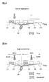
- Fig. 1 is a schematic diagram of carrier aggregation and dual connectivity.
- the user terminal UE communicates with the radio base stations eNB1 and eNB2.
- FIG. 1 shows control signals transmitted and received via a physical downlink control channel (PDCCH: Physical Downlink Control Channel) and a physical uplink control channel (PUCCH: Physical Uplink Control Channel).
- PDCCH Physical Downlink Control Channel
- PUCCH Physical Uplink Control Channel
- DCI Downlink Control Information
- UCI Uplink Control Information
- EPCCH extended physical downlink control channel
- FIG. 1A shows communication between radio base stations eNB1 and eNB2 and a user terminal UE related to carrier aggregation.
- eNB1 is a radio base station (hereinafter referred to as a macro base station) that forms a macro cell
- eNB 2 is a radio base station (hereinafter referred to as a small base station) that forms a small cell.
- the small base station may have a configuration such as RRH (Remote Radio Head) connected to the macro base station.
- RRH Remote Radio Head
- one scheduler for example, a scheduler included in the macro base station eNB1 controls scheduling of a plurality of cells.
- each base station is connected by an ideal backhaul that is a high-speed line such as an optical fiber, for example. .
- FIG. 1B shows communication between the radio base stations eNB1 and eNB2 and the user terminal UE related to dual connectivity.
- both eNB1 and eNB2 are macro base stations.
- a plurality of schedulers are provided independently, and the plurality of schedulers (for example, the scheduler that the macro base station eNB1 has and the scheduler that the macro base station eNB2 has) have one or more jurisdictions. Control cell scheduling.
- the delay between each base station cannot be ignored, for example, an X2 interface It is assumed that they are connected by non-ideal backhaul.
- FIG. 2 is a diagram illustrating an example of a cell configuration in carrier aggregation and dual connectivity.
- the UE is connected to five cells (C1-C5).
- C1 is a PCell (Primary Cell)
- C2-C5 is an SCell (Secondary Cell).
- the uplink control signal is transmitted via the PCell, so the SCell does not need to have the PCell function.
- each radio base station sets a cell group (CG: Cell Group) composed of one or a plurality of cells.
- CG Cell Group
- Each cell group includes one or more cells formed by the same radio base station, or one or more cells formed by the same transmission point such as a transmission antenna device or a transmission station.
- a cell group including PCell is called a master cell group (MCG: Master CG), and a cell group other than the MCG is called a secondary cell group (SCG: Secondary CG).
- MCG Master CG
- SCG Secondary CG
- carrier aggregation of two or more cells can be performed.
- a radio base station in which MCG is set is called a master base station (MeNB: Master eNB), and a radio base station in which SCG is set is called a secondary base station (SeNB: Secondary eNB).
- MCG master eNB
- SCG secondary eNB
- the radio base station or the cell group is also referred to as eNB / CG.
- the total number of cells constituting the MCG and SCG is set to be a predetermined value (for example, 5 cells) or less.
- the predetermined value may be determined in advance or may be dynamically set between the radio base station eNB and the user terminal UE. Further, depending on the implementation of the user terminal UE, the total value of the cells constituting the configurable MCG and SCG and the combination of the cells may be notified to the radio base station eNB as user terminal capability information (UE capability information). .
- the SeNB is also referred to as a special cell (special cell, PUCCH setting cell, etc.) having the same functions (common search space, PUCCH, etc.) as the PCell. )Is required.
- the cell C3 is set as such a special cell.
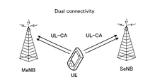
- FIG. 3 is a diagram illustrating an example of a case where each radio base station is connected by UL-CA in dual connectivity.
- the user terminal is connected to each of the MeNB and SeNB by UL-CA.
- the transmission timing of the uplink signal is controlled independently by the MeNB and SeNB. Further, uplink signal transmission power control is also performed independently at the MeNB and SeNB. Therefore, at the timing when the uplink signal transmission to the MeNB and SeNB overlaps, the uplink signal transmission exceeding the allowable maximum power (P CMAX ) of the user terminal may be required. Limiting transmission power as a result of requesting transmission of an uplink signal that exceeds the maximum allowable power of the user terminal is also referred to as “Power-limited”.
- the user terminal must reduce the transmission power based on some rule, by reducing the transmission power or dropping the transmission signal, so that the transmission power falls below the allowable maximum power.
- the quality of the uplink signal unintended by the radio base station may be caused, resulting in an increase in retransmission and a decrease in throughput.
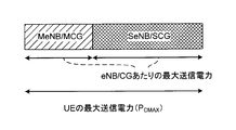
- FIG. 4 is a diagram illustrating an example of uplink transmission power that can be allocated by the user terminal.
- the maximum transmission power per MeNB / MCG and the maximum transmission power per SeNB / SCG are set within the maximum transmission power (P CMAX ) per UE.
- the present inventors set the maximum transmission power per serving cell (P CMAX, c ) by the user terminal from a range sandwiched between an upper limit and a lower limit when dual connectivity is not applied. We focused on the value.
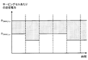
- FIG. 5 is an explanatory diagram illustrating an example in which the maximum transmission power per serving cell varies for each subframe.
- P CMAX, c is set for each subframe by the user terminal such that P CMAX_L, c ⁇ P CMAX, c ⁇ P CMAX_H, c .
- the upper limit P CMAX_H, c and the lower limit P CMAX_L, c are respectively defined as follows.
- P EMAX, c is a value determined by higher layer signaling (for example, a broadcast signal) in the serving cell
- P PowerClass is a specified value.
- ⁇ T C, c and ⁇ T IB, c are offset values, and are determined, for example, to absorb errors for each user terminal.
- MPR c is a maximum power reduction (MPR) in the serving cell, and is a value that varies depending on the number of MCS (Modulation and Coding Scheme) and the number of PRBs (physical resource blocks).
- A-MPR c is an additional maximum power reduction (Additional MPR).
- P-MPR c is a value used for power management.
- MIN and MAX represent functions for extracting the minimum value and the maximum value of the argument list, respectively.
- the upper limit P CMAX_H, c is determined by P EMAX, c or the specified value P PowerClass , it does not vary.
- the lower limit P CMAX_L, c can vary depending on the MPR, but the MPR varies depending on the number of MCSs and PRBs, and thus may vary for each subframe. Therefore, P CMAX, c set between these upper and lower limits may vary from subframe to subframe. Also, P CMAX may vary from subframe to subframe.
- the present inventors replace P EMAX, c in Equations (1) and (2) with a unique value notified for each user terminal and for each CG when applying dual connectivity.
- the present invention has been achieved.
- the present inventors have conceived to replace P EMAX, c with a user terminal specific (UE-specific) value notified by higher layer signaling.
- UE-specific user terminal specific
- a user terminal is connected to two radio base stations (MeNB, SeNB) with dual connectivity
- the present invention is not limited to this.
- the present invention can also be applied when a user terminal is connected to and communicates with three or more radio base stations controlled by independent schedulers.
- the structure connected with a cell group instead of a wireless base station may be sufficient.
- the user terminal sets P CMAX, c using a value specific to the user terminal (terminal specific information).
- terminal specific information the terminal-specific information according to the first embodiment is called Q EMAX, c .
- the name of terminal specific information is not restricted to this.
- Each eNB notifies the user terminal connected by dual connectivity of the maximum transmission power Q EMAX, c per serving cell by higher layer signaling (for example, RRC signaling).
- Q EMAX, c may be notified by being included in an information element (also referred to as an information element or IE (Information Element)).
- IE Information Element
- the sum of Q EMAX, c for each eNB serving cell is preferably set to a value equal to or less than PCMAX .
- Q EMAX per notified serving cell sets the P CMAX, c.
- Q EMAX, c notified from the MeNB is Q EMAX_MeNB, c and Q EMAX
- c notified from the SeNB is Q EMAX_SeNB, c , the upper limit P CMAX_eNB_H, of the maximum transmission power per serving cell formed by each eNB
- P CMAX_eNB_L, c , P CMAX_MeNB_H, c , P CMAX_MeNB_L, c , P CMAX_SeNB_H, c and P CMAX_SeNB_L, c can be expressed as equations (3)-(6), respectively.
- the user terminal sets the maximum transmission power P CMAX_MeNB, c per serving cell formed by the MeNB between the upper limit and the lower limit calculated based on the equations (3) and (4). Further, the user terminal sets the maximum transmission power P CMAX_SeNB, c per serving cell formed by the SeNB between the upper limit and the lower limit calculated based on the equations (5) and (6).
- Q EMAX_MeNB, c and Q EMAX_SeNB respectively from c [Delta] T C, although subtracted c, [Delta] T C, c is in these terms 0 (i.e., no mitigation It may be.
- the maximum transmission power P CMAX per UE is also a value set by the user terminal from a range sandwiched between an upper limit and a lower limit, similarly to P CMAX, c .
- the upper limit P CMAX_H and lower P CMAX_L of P CMAX are respectively defined as follows.
- P CMAX_H MIN ⁇ 10log 10 ⁇ p EMAX, c , P PowerClass ⁇
- P CMAX_L MIN ⁇ 10log 10 ⁇ MIN [p EMAX, c / ( ⁇ t C, c ), p PowerClass / (mpr c ⁇ a-mpr c ⁇ ⁇ t C, c ⁇ ⁇ t IB, c ), p PowerClass / pmpr c ] , P PowerClass ⁇
- p EMAX, c , p PowerClass , mpr c , a-mpr c , pmpr c , ⁇ t C, c and ⁇ t IB, c are P EMAX, c , P PowerClass , MPR c , A-MPR c , P-MPR c , ⁇ T C, c and ⁇ T IB, c are linear values.
- P CMAX is set for each subframe by the user terminal so that P CMAX_L ⁇ P CMAX ⁇ P CMAX_H .
- the maximum transmission power per eNB / CG cannot be set semi-statically for each user terminal and for each CG.
- the user terminal sets P CMAX using a value specific to the user terminal (terminal specific information).
- the terminal specific information according to the second embodiment is referred to as PeNB .
- Each eNB notifies (configures) the maximum transmission power P eNB per eNB to the user terminal connected by dual connectivity through higher layer signaling (for example, RRC signaling).
- Each PeNB may be notified by being included in an information element.
- the sum of P eNB for each eNB is preferably set to a value equal to or less than P CMAX.
- the user terminal sets the P CMAX_eNB per each eNB (P CMAX for the eNB). For example, P MeNB the P eNB notified from MeNB, when the P eNB and P SeNB notified from SeNB, the upper limit of the maximum transmission power per each eNB, the lower limit P CMAX_MeNB_H, P CMAX_MeNB_L, P CMAX_SeNB_H and P CMAX_SeNB_L Can be expressed as in the formulas (9) to (12), respectively.
- P CMAX_MeNB_H MIN ⁇ P MeNB , 10log 10 ⁇ p EMAX, c , P PowerClass ⁇ Formula (10)
- P CMAX_MeNB_L MIN ⁇ 10log 10 ⁇ p MeNB / ⁇ t C, c , 10log 10 ⁇ MIN [p EMAX, c / ( ⁇ t C, c ), p PowerClass / (mpr c ⁇ a-mpr c ⁇ ⁇ t C, c ⁇ ⁇ t IB , c ), p PowerClass / pmpr c ], P PowerClass ⁇ Formula (11)
- P CMAX_SeNB_H MIN ⁇ P SeNB , 10log 10 ⁇ p EMAX, c , P PowerClass ⁇ Formula (12)
- P CMAX_SeNB_L MIN ⁇ 10log 10 ⁇ p SeNB / ⁇ t C, c , 10log 10 ⁇ MIN [p EMAX,
- ⁇ on the right side of the above formulas (9) to (12) represents that the sum of the serving cells belonging to the MeNB / MCG is taken in the case of formulas (9) and (10), and formulas (11) and (12 ) Indicates that a sum is taken for serving cells belonging to SeNB / SCG.
- p MeNB and p SeNB are linear values of P MeNB and P SeNB , respectively.
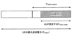
- the user terminal sets the maximum transmission power P CMAX_MeNB per MeNB between the upper limit and the lower limit calculated based on the equations (9) and (10). Further, the user terminal sets the maximum transmission power P CMAX_SeNB per SeNB between the upper limit and the lower limit calculated based on the equations (11) and (12). Accordingly, as shown in FIG. 4, the maximum transmission power per MeNB (P CMAX_MeNB ) and the maximum transmission power per SeNB (P CMAX_SeNB ) can be set within the maximum transmission power (P CMAX ) per UE.
- 10log 10 ⁇ p MeNB / ⁇ t C, c and 10log 10 ⁇ p SeNB / ⁇ t C, c may be replaced with P MeNB and P SeNB (that is, no relaxation value is applied). Even if it is) Further, as long as P MeNB and P SeNB is set in a range satisfying P MeNB ⁇ P Powerclass and P SeNB ⁇ P Powerclass, Equation (9) - P Powerclass included in the right-hand side of (12) can be omitted.
- the user terminal determines the maximum transmission power for each eNB using Equations (7) and (8), as in the case of not applying dual connectivity. .
- the maximum transmission power is set using Equations (7) and (8) for the eNB.
- the power ratio assigned to each eNB can be flexibly changed even in dual connectivity. And a decrease in uplink throughput can be suppressed. Also, since the changes to the existing P CMAX decision rules are very small, the impact on user terminal implementation is small.
- FIG. 6 is a diagram illustrating an example of uplink transmission power that can be allocated by the user terminal.
- P CMAX_MeNB_H , P CMAX_MeNB_L , P CMAX_SeNB_H and P CMAX_SeNB_L are obtained by the method described in the second embodiment, and P CMAX_MeNB and P CMAX_SeNB are set.
- power for (P CMAX_MeNB_H ⁇ P CMAX_MeNB ) is not allocated for MeNB
- power for (P CMAX_SeNB_H ⁇ P CMAX_SeNB ) is allocated for SeNB , which may cause a decrease in uplink throughput.
- P CMAX_eNB_H the upper limit of the maximum transmission power for each eNB
- P CMAX_eNB set for a predetermined eNB is used. calculates the P CMAX_eNB_H for another eNB Te, sets the P CMAX_eNB of the different eNB.
- P CMAX_eNB_H and P CMAX_eNB_L for one eNB P CMAX_eNB of the eNB is determined. Thereafter, P CMAX_eNB_H for the other eNB is determined by the difference (P CMAX ⁇ P CMAX_eNB ) between P CMAX and the previously determined P CMAX_eNB .
- FIG.7 and FIG.8 is a figure explaining the calculation method of the maximum transmission power per each eNB / CG which concerns on the 3rd Embodiment of this invention.
- P CMAX_SeNB from defining a P CMAX_SeNB initially, sets the P CMAX_MeNB.
- the user terminal determines P CMAX_SeNB based on P CMAX_SeNB_H and P CMAX_SeNB_L calculated using equations (11) and (12) (FIG. 7).
- the user terminal (P CMAX -P CMAX_SeNB) is regarded as P CMAX_MeNB_H, seek P CMAX_MeNB_L therefrom in consideration of the MPR, etc., determine the P CMAX_MeNB to fit in these ranges (Fig. 8).
- the user terminal may be regarded as the maximum transmission power P MeNB per MeNB the P CMAX_MeNB_H, for example may be obtained P CMAX_MeNB_L by formula (10).
- FIG. 8 has a smaller area to which power is not allocated.
- the SeNB decides first, the area of (P CMAX_SeNB_H ⁇ P CMAX_SeNB ) can be reused for power allocation, and power can be used efficiently.
- the MeNB is determined first, it is possible to use an area of (P CMAX_MeNB_H ⁇ P CMAX_MeNB ) for SeNB power allocation.
- the user terminal determines the maximum transmission power per eNB one by one instead of independently for each eNB. That is, when the maximum transmission power is determined for a predetermined eNB, the maximum transmission power in the remaining eNBs can be determined in a range obtained by subtracting the maximum transmission power for the predetermined eNB from the maximum transmission power of the user terminal. Thereby, it becomes possible to allocate efficiently the transmission power which a user terminal can utilize to each eNB.
- 3rd Embodiment was applied to the calculation method of the maximum transmission power per eNB / CG which concerns on 2nd Embodiment, it is not restricted to this.
- the third embodiment may be applied to the method for calculating the maximum transmission power per cell according to the first embodiment.
- the order of determining the maximum transmission power of each eNB in the third embodiment may be set in advance in the user terminal. For example, it may be determined to be determined in the order of SeNB and MeNB. In addition, information on the order and information on whether or not to determine the maximum transmission power independently for each radio base station are reported from the radio base station by higher layer signaling (for example, RRC signaling), broadcast information, or the like. May be. For example, information regarding an eNB whose maximum transmission power should be determined first may be included in an information element including terminal-specific information regarding the maximum transmission power.
- the maximum transmission power setting process shown in each of the above embodiments is a case where the uplink signal transmission timing is not synchronized (also referred to as asynchronous dual connectivity) in a plurality of eNB / CGs connected by dual connectivity. Even can be applied.
- the radio base station needs signaling for notifying specific information regarding the maximum transmission power of the uplink signal for each user terminal. Whether or not to do so may be determined from user terminal capability information (UE capability information).
- UE capability information user terminal capability information
- user terminal capability information may be defined as follows. For example, user terminal capability information indicating whether or not the maximum transmission power for each radio base station can be set may be defined. Further, user terminal capability information indicating whether asynchronous dual connectivity can be supported may be defined. Moreover, you may prescribe
- the user terminal capability information is notified from the user terminal to the radio base station before the dual connectivity is set.
- the radio base station may be configured to notify the user terminal specific information when it is determined that the user terminal can perform the maximum transmission power setting process according to the above embodiment based on the user terminal capability information. Good. For example, when the radio base station determines that the user terminal cannot dynamically share the transmission power between the eNB / CG, the radio base station performs quasi-static for each eNB / CG based on the above embodiment with respect to the user terminal.
- the maximum transmission power may be distributed to (semi-static).
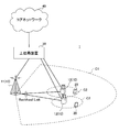
- FIG. 9 is a schematic configuration diagram showing an example of a wireless communication system according to an embodiment of the present invention.
- the radio communication system 1 is in a cell formed by a plurality of radio base stations 10 (11 and 12) and each radio base station 10, and is configured to be able to communicate with each radio base station 10.
- Each of the radio base stations 10 is connected to the higher station apparatus 30 and connected to the core network 40 via the higher station apparatus 30.
- the radio base station 11 is composed of, for example, a macro base station having a relatively wide coverage, and forms a macro cell C1.
- the radio base station 12 is configured by a small base station having local coverage, and forms a small cell C2.
- the number of radio base stations 11 and 12 is not limited to the number shown in FIG.
- the same frequency band may be used, or different frequency bands may be used.
- the radio base stations 11 and 12 are connected to each other via an inter-base station interface (for example, optical fiber, X2 interface).
- the macro base station 11 may be referred to as a radio base station, an eNodeB (eNB), a transmission point, or the like.
- the small base station 12 may be called a pico base station, a femto base station, a Home eNodeB (HeNB), a transmission point, an RRH (Remote Radio Head), or the like.
- the user terminal 20 is a terminal that supports various communication methods such as LTE and LTE-A, and may include not only a mobile communication terminal but also a fixed communication terminal.
- the user terminal 20 can execute communication with other user terminals 20 via the radio base station 10.
- the upper station apparatus 30 includes, for example, an access gateway apparatus, a radio network controller (RNC), a mobility management entity (MME), and the like, but is not limited thereto.
- RNC radio network controller
- MME mobility management entity
- OFDMA Orthogonal Frequency Division Multiple Access
- SC-FDMA Single Carrier Frequency Division Multiple Access
- the uplink and downlink radio access methods are not limited to these combinations.
- a downlink shared channel (PDSCH: Physical Downlink Shared Channel) shared by each user terminal 20, a downlink control channel (PDCCH: Physical Downlink Control Channel, EPDCCH: Enhanced Physical Downlink Control Channel). ), A broadcast channel (PBCH: Physical Broadcast Channel) and the like are used.
- PDSCH Physical Downlink Shared Channel
- PDCCH Physical Downlink Control Channel
- EPDCCH Enhanced Physical Downlink Control Channel
- PBCH Physical Broadcast Channel
- User data, higher layer control information, and predetermined SIB (System Information Block) are transmitted by PDSCH.
- Downlink control information (DCI: Downlink Control Information) is transmitted by PDCCH and EPDCCH.
- MIB Master Information Block
- an uplink shared channel (PUSCH: Physical Uplink Shared Channel) shared by each user terminal 20, an uplink control channel (PUCCH: Physical Uplink Control Channel), or the like is used as an uplink channel.
- PUSCH Physical Uplink Shared Channel
- PUCCH Physical Uplink Control Channel
- User data and higher layer control information are transmitted by PUSCH.
- FIG. 10 is an overall configuration diagram of the radio base station 10 according to the present embodiment.
- the radio base station 10 includes a plurality of transmission / reception antennas 101 for MIMO transmission, an amplifier unit 102, a transmission / reception unit (reception unit) 103, a baseband signal processing unit 104, a call processing unit 105, and a transmission path interface 106.
- the transmission / reception unit 103 includes a transmission unit and a reception unit.
- User data transmitted from the radio base station 10 to the user terminal 20 via the downlink is input from the higher station apparatus 30 to the baseband signal processing unit 104 via the transmission path interface 106.
- PDCP Packet Data Convergence Protocol
- RLC Radio Link Control
- MAC Medium Access
- Retransmission control for example, HARQ (Hybrid Automatic Repeat reQuest) transmission processing
- HARQ Hybrid Automatic Repeat reQuest
- the downlink control signal is also subjected to transmission processing such as channel coding and inverse fast Fourier transform, and transferred to each transmitting / receiving unit 103.
- Each transmitting / receiving unit 103 converts the downlink signal output from the baseband signal processing unit 104 by precoding for each antenna into a radio frequency band and transmits the converted signal.
- the radio frequency signal frequency-converted by the transmission / reception unit 103 is amplified by the amplifier unit 102 and transmitted from the transmission / reception antenna 101.
- the radio frequency signal received by each transmitting / receiving antenna 101 is amplified by the amplifier unit 102.
- Each transmitting / receiving unit 103 receives the upstream signal amplified by the amplifier unit 102.
- the transmission / reception unit 103 converts the frequency of the received signal into a baseband signal and outputs it to the baseband signal processing unit 104.
- the baseband signal processing unit 104 performs fast Fourier transform (FFT) processing, inverse discrete Fourier transform (IDFT: Inverse Discrete Fourier Transform) processing, and error correction on user data included in the input upstream signal.
- FFT fast Fourier transform
- IDFT inverse discrete Fourier transform
- Decoding, MAC retransmission control reception processing, RLC layer, and PDCP layer reception processing are performed and transferred to the upper station apparatus 30 via the transmission path interface 106.
- the call processing unit 105 performs call processing such as communication channel setting and release, state management of the radio base station 10, and radio resource management.
- the transmission path interface 106 transmits and receives signals to and from the higher station apparatus 30 via a predetermined interface. Further, the transmission path interface 106 may transmit / receive a signal (backhaul signaling) to / from an adjacent radio base station via an interface between base stations (for example, an optical fiber or an X2 interface).
- a signal backhaul signaling
- FIG. 11 is a main functional configuration diagram of the baseband signal processing unit 104 included in the radio base station 10 according to the present embodiment.
- the baseband signal processing unit 104 included in the radio base station 10 includes a control unit 301, a transmission signal generation unit 302, a mapping unit 303, a demapping unit 304, and a received signal decoding unit 305. , At least.
- the control unit 301 performs scheduling (allocation control) of radio resources for downlink signals and uplink signals based on instruction information from the higher station apparatus 30 and feedback information from each user terminal 20. That is, the control unit 301 has a function as a scheduler. In addition, when the other radio base station 10 and the higher station apparatus 30 function as a scheduler of the radio base station 10, the control unit 301 does not need to function as a scheduler.
- control unit 301 controls scheduling of a downlink reference signal, a downlink data signal transmitted by PDSCH, a downlink control signal transmitted by PDCCH and / or EPDCCH, and the like.
- control unit 301 controls scheduling such as an uplink reference signal, an uplink data signal transmitted by PUSCH, an uplink control signal transmitted by PUCCH and / or PUSCH, and an RA preamble transmitted by PRACH.
- DCI downlink control information
- control unit 301 may control the transmission signal generation unit 302 and the mapping unit 303 in order to adjust the uplink signal transmission power of the user terminal 20 connected to the radio base station 10.
- the control unit 301 transmits an uplink signal based on PHR (Power Headroom Report) and channel state information (CSI) reported from the user terminal 20, an uplink data error rate, the number of HARQ retransmissions, and the like.
- An instruction is given to the transmission signal generation unit 302 to generate a transmission power control (TPC) command for controlling power, and the mapping unit 303 includes the TPC command in downlink control information (DCI) and notifies the user terminal 20 Can be controlled.
- TPC transmission power control
- DCI downlink control information
- the radio base station 10 can specify the transmission power of the uplink signal requested from the user terminal 20.
- the PHR may be notified by being included in a MAC CE (Control Element).
- the control unit 301 can acquire information on uplink transmission power to each radio base station 10 to which the user terminal 20 is connected. Specifically, the control unit 301 acquires information on the transmission power of a cell belonging to the own station based on the PHR notified from the user terminal 20. Note that the control unit 301 uses the PUSCH bandwidth, channel state (path loss, etc.), transmission power density (PSD), MCS of cells formed by other radio base stations 10 for information related to transmission power of cells that do not belong to its own station. Levels, channel quality, etc. may be estimated. Further, the control unit 301 may calculate (estimate) the total surplus transmission power of the user terminal 20 from these pieces of information.
- control unit 301 controls the transmission signal generation unit 302 and the mapping unit 303 so as to generate and transmit terminal-specific information regarding the maximum transmission power of the uplink signal to the user terminal 20.
- the terminal specific information may be, for example, the maximum transmission power per serving cell Q EMAX, c (first embodiment) and the maximum transmission power PeNB (second embodiment) per radio base station.
- the terminal specific information is determined so that the sum of all the maximum transmission powers indicated by the terminal specific information for each radio base station 10 to which the user terminal 20 is connected is equal to or less than the maximum transmission power of the user terminal 20. It is preferable that For this reason, the control unit 301 exchanges terminal specific information with the upper station apparatus 30 and other wireless base stations 10 via the transmission path interface 106, and determines the maximum transmission power to be included in the terminal specific information. May be.
- the terminal-specific information may include the index indicating the maximum transmission power value, and the user terminal 20 derives the maximum transmission power from the index. May be.
- the transmission signal generation unit 302 generates a downlink control signal, a downlink data signal, a downlink reference signal, and the like whose assignment is determined by the control unit 301 and outputs them to the mapping unit 303. Specifically, based on an instruction from the control unit 301, the transmission signal generation unit 302 generates a DL assignment for notifying downlink signal allocation information and a UL grant for notifying uplink signal allocation information. Also, the downlink data signal is subjected to encoding processing and modulation processing according to the coding rate and modulation scheme determined based on CSI from each user terminal 20 and the like.
- the transmission signal generation unit 302 generates higher layer signaling (for example, RRC signaling) including terminal specific information as a downlink data signal based on an instruction from the control unit 301.
- the terminal specific information may be configured to be included in the information element.
- the mapping unit 303 maps the downlink signal generated by the transmission signal generation unit 302 to a radio resource based on an instruction from the control unit 301, and outputs the radio signal to the transmission / reception unit 103.
- the demapping unit 304 demaps the signal received by the transmission / reception unit 103 and outputs the separated signal to the reception signal decoding unit 305. Specifically, the demapping unit 304 demaps the uplink signal transmitted from the user terminal 20.
- the reception signal decoding unit 305 decodes a signal transmitted from the user terminal 20 through the uplink control channel (PRACH, PUCCH) (for example, a delivery confirmation signal (HARQ-ACK)), a data signal transmitted through the PUSCH, and the like. Output to the unit 301. Information included in the MAC CE notified from the user terminal 20 is also output to the control unit 301.
- PRACH uplink control channel
- PUCCH uplink control channel
- HARQ-ACK delivery confirmation signal
- FIG. 12 is an overall configuration diagram of the user terminal 20 according to the present embodiment.
- the user terminal 20 includes a plurality of transmission / reception antennas 201 for MIMO transmission, an amplifier unit 202, a transmission / reception unit 203, a baseband signal processing unit 204, and an application unit 205.
- the transmission / reception unit 203 may include a transmission unit and a reception unit.
- radio frequency signals received by a plurality of transmission / reception antennas 201 are amplified by an amplifier 202, respectively.
- Each transmitting / receiving unit 203 receives the downlink signal amplified by the amplifier unit 202.
- the transmission / reception unit 203 converts the frequency of the received signal into a baseband signal and outputs it to the baseband signal processing unit 204.
- the baseband signal processing unit 204 performs FFT processing, error correction decoding, retransmission control reception processing, and the like on the input baseband signal.
- the downlink user data is transferred to the application unit 205.
- the application unit 205 performs processing related to layers higher than the physical layer and the MAC layer.
- broadcast information in the downlink data is also transferred to the application unit 205.
- uplink user data is input from the application unit 205 to the baseband signal processing unit 204.
- the baseband signal processing unit 204 performs retransmission control transmission processing (for example, HARQ transmission processing), channel coding, precoding, discrete Fourier transform (DFT) processing, IFFT processing, and the like. It is transferred to the transmission / reception unit 203.
- the transmission / reception unit 203 converts the baseband signal output from the baseband signal processing unit 204 into a radio frequency band and transmits it.
- the radio frequency signal frequency-converted by the transmission / reception unit 203 is amplified by the amplifier unit 202 and transmitted from the transmission / reception antenna 201.
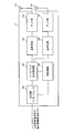
- FIG. 13 is a main functional configuration diagram of the baseband signal processing unit 204 included in the user terminal 20.
- the baseband signal processing unit 204 included in the user terminal 20 includes a control unit 401, a transmission signal generation unit 402, a mapping unit 403, a demapping unit 404, a received signal decoding unit 405, A maximum transmission power setting unit 406 and a PH report generation unit 411 are included at least.
- the control unit 401 obtains, from the received signal decoding unit 405, the downlink control signal (signal transmitted on the PDCCH) and the downlink data signal (signal transmitted on the PDSCH) transmitted from the radio base station 10.
- the control unit 401 generates an uplink control signal (for example, an acknowledgment signal (HARQ-ACK)) or an uplink data signal based on a downlink control signal, a result of determining whether retransmission control is possible for the downlink data signal, or the like. Control. Specifically, the transmission signal generation unit 402 and the mapping unit 403 are controlled.
- the transmission signal generation unit 402 generates an uplink control signal such as a delivery confirmation signal (HARQ-ACK) or channel state information (CSI) based on an instruction from the control unit 401.
- the transmission signal generation unit 402 generates an uplink data signal based on an instruction from the control unit 401.
- the control unit 401 instructs the transmission signal generation unit 402 to generate an uplink data signal when the UL grant is included in the downlink control signal notified from the radio base station.
- the mapping unit 403 maps the uplink signal generated by the transmission signal generation unit 402 to a radio resource based on an instruction from the control unit 401, and outputs the radio signal to the transmission / reception unit 203.
- control unit 401 controls the uplink transmission power of the user terminal 20. Specifically, the control unit 401 controls the transmission power of each cell (CC) based on signaling (for example, a TPC command) from each radio base station 20. Here, the control unit 401 controls the uplink transmission power so as to be equal to or less than the maximum transmission power of the uplink signal to each radio base station 10 set by the maximum transmission power setting unit 406. For this reason, the control unit 401 outputs terminal-specific information regarding the maximum transmission power of the uplink signal included in the received higher layer signaling to the maximum transmission power setting unit 406.
- the maximum transmission power setting unit 406 sets the maximum transmission power of the uplink signal to the predetermined radio base station based on the terminal specific information about the predetermined radio base station input from the control unit 401. Further, the maximum transmission power setting section 406 outputs information related to the set maximum transmission power of the uplink signal to each radio base station to the control section 401.
- the maximum transmission power setting unit 406 uses the Q EMAX_MeNB, c notified from the MeNB to calculate the maximum transmission power P CMAX_MeNB, c per serving cell formed by the MeNB based on the equations (3) and (4). Set. Further, the maximum transmission power P CMAX_SeNB, c per serving cell formed by the SeNB is set based on the equations (5) and (6) using Q EMAX_SeNB, c notified from the SeNB (first embodiment) ).
- the maximum transmission power setting part 406 may set the maximum transmission power P CMAX_MeNB per MeNB based on Formula (9) and (10) using PMeNB notified from MeNB . Moreover, you may set the maximum transmission power PCMAX_SeNB per SeNB based on Formula (11) and (12) using PSeNB notified from SeNB (2nd Embodiment).
- the maximum transmission power setting unit 406 sets the maximum transmission power for the predetermined eNB
- the maximum transmission power in the remaining eNBs is excluded from the maximum transmission power for the predetermined eNB from the maximum transmission power of the user terminal 20 It can be determined to be included in the range (third embodiment). For example, when connecting with three eNBs, after determining the maximum transmission power for each of the two eNBs based on the terminal-specific information, the power obtained by removing these determined maximum transmission powers from P CMAX is the remaining 1 You may determine as an upper limit of the maximum transmission power of one eNB.
- the transmission signal generation unit 402 can set the maximum transmission power of an uplink signal to a predetermined radio base station based on the terminal specific information by the maximum transmission power setting unit 406 as user terminal capability information (UE capability information). It is preferable to produce.
- UE capability information user terminal capability information
- the PH report generation unit 411 sets the PH (Power Headroom) for each eNB / CG, the transmission power of the uplink signal requested by the eNB / CG, and the uplink to the eNB / CG.
- the PHR is calculated from the difference between the maximum transmission power of the signal and output to the transmission signal generation unit 402. Note that the PHR may be generated based on the upper limit of the maximum transmission power of the uplink signal to the eNB / CG.
- the demapping unit 404 demaps the signal received by the transmission / reception unit 203 and outputs the separated signal to the reception signal decoding unit 405. Specifically, the demapping unit 404 demaps the downlink signal transmitted from the radio base station 10.
- Received signal decoding section 405 decodes a downlink control signal (PDCCH signal) transmitted on the downlink control channel (PDCCH), and feeds back a delivery confirmation signal for scheduling information (assignment information to uplink resources) and the downlink control signal.
- a downlink control signal (PDCCH signal) transmitted on the downlink control channel (PDCCH)
- a delivery confirmation signal for scheduling information (assignment information to uplink resources) and the downlink control signal.
- the information regarding the cell to be processed, the TPC command, and the like are output to the control unit 401.
Landscapes
- Engineering & Computer Science (AREA)
- Computer Networks & Wireless Communication (AREA)
- Signal Processing (AREA)
- Quality & Reliability (AREA)
- Mobile Radio Communication Systems (AREA)
Abstract
Description
PCMAX_H,c=MIN{PEMAX,c, PPowerClass}
式(2)
PCMAX_L,c=MIN{PEMAX,c-ΔTC,c, PPowerClass-MAX(MPRc+A-MPRc+ΔTIB,c+ΔTC,c, P-MPRc)}
本発明の第1の実施形態では、ユーザ端末は、ユーザ端末固有の値(端末固有情報)を用いてPCMAX,cを設定する。既存のPEMAX,cと区別するため、第1の実施の形態に係る端末固有情報を、QEMAX,cと呼ぶ。なお、端末固有情報の呼称はこれに限られない。
PCMAX_MeNB_H,c=MIN{QEMAX_MeNB,c, PPowerClass}
式(4)
PCMAX_MeNB_L,c=MIN{QEMAX_MeNB,c-ΔTC,c, PPowerClass-MAX(MPRc+A-MPRc+ΔTIB,c+ΔTC,c, P-MPRc)}
式(5)
PCMAX_SeNB_H,c=MIN{QEMAX_SeNB,c, PPowerClass}
式(6)
PCMAX_SeNB_L,c=MIN{QEMAX_SeNB,c-ΔTC,c, PPowerClass-MAX(MPRc+A-MPRc+ΔTIB,c+ΔTC,c, P-MPRc)}
UEあたりの最大送信電力PCMAXも、PCMAX,cと同様に、上限と下限に挟まれた範囲からユーザ端末が設定する値である。ここで、PCMAXの上限PCMAX_Hと下限PCMAX_Lは、それぞれ以下のように規定されている。
PCMAX_H=MIN{10log10ΣpEMAX,c, PPowerClass}
式(8)
PCMAX_L=MIN{10log10ΣMIN[pEMAX,c/(ΔtC,c), pPowerClass/(mprc・a-mprc・ΔtC,c・ΔtIB,c), pPowerClass/pmprc], PPowerClass}
PCMAX_MeNB_H=MIN{PMeNB, 10log10ΣpEMAX,c, PPowerClass}
式(10)
PCMAX_MeNB_L=MIN{10log10ΣpMeNB/ΔtC,c, 10log10ΣMIN[pEMAX,c/(ΔtC,c), pPowerClass/(mprc・a-mprc・ΔtC,c・ΔtIB,c), pPowerClass/pmprc], PPowerClass}
式(11)
PCMAX_SeNB_H=MIN{PSeNB, 10log10ΣpEMAX,c, PPowerClass}
式(12)
PCMAX_SeNB_L=MIN{10log10ΣpSeNB/ΔtC,c, 10log10ΣMIN[pEMAX,c/(ΔtC,c), pPowerClass/(mprc・a-mprc・ΔtC,c・ΔtIB,c), pPowerClass/pmprc], PPowerClass}
上述のように、MeNB/MCGとSeNB/SCGとで送信電力を完全に分割するためには、両eNB/CGの最大送信電力の最大値、すなわちPCMAX_eNB_Hの和やPCMAX_eNB_H,cの和が、PCMAXを超えないようにしなければならない。しかしながら、実際の最大送信電力は、設定可能な範囲からユーザ端末が設定する。したがって、両eNB/CGともに、PCMAX_eNB_HやPCMAX_eNB_H,cまで電力が使われる可能性は小さい。このように、各eNB/CGで別々に最大送信電力を設定していることにより、電力が効率的に割り当てられない場合が生じる恐れがある。
なお、上記の各実施形態に示した最大送信電力の設定処理は、デュアルコネクティビティで接続する複数のeNB/CGで、上り信号の送信タイミングが同期していない場合(非同期デュアルコネクティビティともいう)であっても、適用することができる。
以下、本発明の一実施の形態に係る無線通信システムの構成について説明する。この無線通信システムでは、上記各実施の形態に係る無線通信方法が適用される。
Claims (10)
- 第1の無線基地局及び第2の無線基地局を含む複数の無線基地局に接続するユーザ端末であって、
各無線基地局に対してそれぞれ上り信号を送信する送信部と、
上り信号の最大送信電力に関する前記第1の無線基地局についての端末固有情報を受信する受信部と、
前記第1の無線基地局についての端末固有情報に基づいて、前記第1の無線基地局への最大送信電力を設定する最大送信電力設定部と、を有することを特徴とするユーザ端末。 - 前記受信部は、上り信号の最大送信電力に関する前記複数の無線基地局についてのそれぞれの端末固有情報を受信し、
前記最大送信電力設定部は、前記複数の無線基地局についてのそれぞれの端末固有情報に基づいて、前記複数の無線基地局それぞれへの最大送信電力を設定することを特徴とする請求項1に記載のユーザ端末。 - 無線基地局についての端末固有情報は、各無線基地局についての端末固有情報が示す全ての最大送信電力の和が、当該ユーザ端末の最大送信電力以下となるように決定されていることを特徴とする請求項2に記載のユーザ端末。
- 無線基地局についての端末固有情報は、当該無線基地局が形成するサービングセルあたりの最大送信電力であり、
前記最大送信電力設定部は、上り信号の最大送信電力のうち、サービングセルあたりの最大送信電力を設定することを特徴とする請求項1から請求項3のいずれかに記載のユーザ端末。 - 無線基地局についての端末固有情報は、当該無線基地局あたりの最大送信電力であり、
前記最大送信電力設定部は、上り信号の最大送信電力のうち、無線基地局あたりの最大送信電力を設定することを特徴とする請求項1から請求項3のいずれかに記載のユーザ端末。 - 前記最大送信電力設定部は、前記第1の無線基地局についての端末固有情報に基づいて、前記第1の無線基地局への最大送信電力の上限及び下限を算出し、当該上限及び下限の範囲内で最大送信電力を設定することを特徴とする請求項1から請求項5のいずれかに記載のユーザ端末。
- 前記最大送信電力設定部は、前記第1の無線基地局への最大送信電力に基づいて、前記第2の無線基地局への最大送信電力の上限を算出し、当該上限以下となるように前記第2の無線基地局への最大送信電力を設定することを特徴とする請求項6に記載のユーザ端末。
- ユーザ端末が接続する複数の無線基地局のうちの一の無線基地局であって、
上り信号の最大送信電力に関する端末固有情報を送信する送信部と、
前記端末固有情報に基づいて最大送信電力が設定された上り信号を受信する受信部と、を有することを特徴とする無線基地局。 - 第1の無線基地局及び第2の無線基地局を含む複数の無線基地局に接続するユーザ端末に係る無線通信方法であって、
各無線基地局に対してそれぞれ上り信号を送信する工程と、
上り信号の最大送信電力に関する前記第1の無線基地局についての端末固有情報を受信する工程と、
前記第1の無線基地局についての端末固有情報に基づいて、前記第1の無線基地局への最大送信電力を設定する工程と、を有することを特徴とする無線通信方法。 - 第1の無線基地局と第2の無線基地局とを含む複数の無線基地局とユーザ端末が接続する無線通信システムであって、
前記ユーザ端末は、各無線基地局に対してそれぞれ上り信号を送信する送信部と、
上り信号の最大送信電力に関する前記第1の無線基地局についての端末固有情報を受信する受信部と、
前記第1の無線基地局についての端末固有情報に基づいて、前記第1の無線基地局への最大送信電力を設定する最大送信電力設定部と、を有することを特徴とする無線通信システム。
Priority Applications (5)
| Application Number | Priority Date | Filing Date | Title |
|---|---|---|---|
| EP15788678.9A EP3142428B1 (en) | 2014-05-08 | 2015-05-08 | User equipment, radio base station, radio communication method, and radio communication system |
| ES15788678T ES2838678T3 (es) | 2014-05-08 | 2015-05-08 | Equipo de usuario, estación base de radio, método de comunicación por radio y sistema de comunicación por radio |
| JP2016517929A JP6713411B2 (ja) | 2014-05-08 | 2015-05-08 | ユーザ端末及び無線通信方法 |
| US15/309,368 US20170078975A1 (en) | 2014-05-08 | 2015-05-08 | User terminal, radio base station and radio communication method |
| US15/873,525 US10306561B2 (en) | 2014-05-08 | 2018-01-17 | User terminal, radio base station, radio communication method and radio communication system |
Applications Claiming Priority (2)
| Application Number | Priority Date | Filing Date | Title |
|---|---|---|---|
| JP2014097079 | 2014-05-08 | ||
| JP2014-097079 | 2014-05-08 |
Related Child Applications (2)
| Application Number | Title | Priority Date | Filing Date |
|---|---|---|---|
| US15/309,368 A-371-Of-International US20170078975A1 (en) | 2014-05-08 | 2015-05-08 | User terminal, radio base station and radio communication method |
| US15/873,525 Continuation US10306561B2 (en) | 2014-05-08 | 2018-01-17 | User terminal, radio base station, radio communication method and radio communication system |
Publications (1)
| Publication Number | Publication Date |
|---|---|
| WO2015170726A1 true WO2015170726A1 (ja) | 2015-11-12 |
Family
ID=54392575
Family Applications (1)
| Application Number | Title | Priority Date | Filing Date |
|---|---|---|---|
| PCT/JP2015/063244 Ceased WO2015170726A1 (ja) | 2014-05-08 | 2015-05-08 | ユーザ端末、無線基地局、無線通信方法及び無線通信システム |
Country Status (5)
| Country | Link |
|---|---|
| US (2) | US20170078975A1 (ja) |
| EP (1) | EP3142428B1 (ja) |
| JP (1) | JP6713411B2 (ja) |
| ES (1) | ES2838678T3 (ja) |
| WO (1) | WO2015170726A1 (ja) |
Cited By (1)
| Publication number | Priority date | Publication date | Assignee | Title |
|---|---|---|---|---|
| JP2021514583A (ja) * | 2018-02-14 | 2021-06-10 | 華為技術有限公司Huawei Technologies Co.,Ltd. | 電力制御方法および装置 |
Families Citing this family (10)
| Publication number | Priority date | Publication date | Assignee | Title |
|---|---|---|---|---|
| US10536904B2 (en) | 2016-05-09 | 2020-01-14 | Ofinno, Llc | Parallel transmission in a wireless device and wireless network |
| US20170325174A1 (en) | 2016-05-09 | 2017-11-09 | Ofinno Technologies, Llc | Uplink transmission power control in a wireless device and wireless network |
| US10750410B2 (en) | 2016-09-30 | 2020-08-18 | Huawei Technologies Co., Ltd. | Ultra reliable low latency connection support in radio access networks |
| EP3537819B1 (en) * | 2017-03-31 | 2021-10-20 | CloudMinds (Shanghai) Robotics Co., Ltd. | Resource scheduling method and base station |
| US10548096B2 (en) | 2017-04-21 | 2020-01-28 | Samsung Electronics Co., Ltd. | Information type multiplexing and power control |
| KR102236092B1 (ko) * | 2017-05-05 | 2021-04-02 | 차이나 아카데미 오브 텔레커뮤니케이션즈 테크놀로지 | 멀티 빔 구성을 위한 전력 제어 프레임워크 |
| US20180367288A1 (en) * | 2017-06-16 | 2018-12-20 | Huawei Technologies Co., Ltd. | Dynamic activation and deactivation of packet duplication |
| WO2019215858A1 (ja) * | 2018-05-09 | 2019-11-14 | 株式会社Nttドコモ | 基地局装置及びユーザ装置 |
| CN110831140A (zh) | 2018-08-10 | 2020-02-21 | 华为技术有限公司 | 一种功率确定方法和装置 |
| US11388684B2 (en) | 2019-04-01 | 2022-07-12 | Lenovo (Singapore) Pte. Ltd. | Method and apparatus for managing the maximum power on a secondary carrier |
Citations (1)
| Publication number | Priority date | Publication date | Assignee | Title |
|---|---|---|---|---|
| JP2013529403A (ja) * | 2010-04-01 | 2013-07-18 | パナソニック株式会社 | 物理ランダムアクセスチャネルの送信電力制御 |
Family Cites Families (12)
| Publication number | Priority date | Publication date | Assignee | Title |
|---|---|---|---|---|
| US8036151B2 (en) * | 2006-12-17 | 2011-10-11 | Qualcomm Incorporated | Power-based rate signaling for cellular uplink |
| EP2244515A1 (en) | 2009-04-23 | 2010-10-27 | Panasonic Corporation | Logical channel prioritization procedure for generating multiple uplink transport blocks |
| CN102045825A (zh) * | 2009-10-14 | 2011-05-04 | 华为技术有限公司 | 一种lte系统上行功率的控制方法、基站、移动终端 |
| US9144038B2 (en) * | 2010-11-05 | 2015-09-22 | Samsung Electronics Co., Ltd. | Method and apparatus for calculating power headroom in carrier aggregation mobile communication system |
| KR20140091775A (ko) * | 2011-08-12 | 2014-07-22 | 인터디지탈 패튼 홀딩스, 인크 | 전력 제어 및 타이밍 어드밴스를 위한 방법, 장치 및 시스템 |
| EP2693815A1 (en) * | 2012-08-03 | 2014-02-05 | Panasonic Corporation | Power headroom reporting for in-device coexistence interference avoidance |
| US9386619B2 (en) * | 2013-02-22 | 2016-07-05 | Htc Corporation | Method of handling a cell addition for dual connectivity and related communication device |
| PL3223470T3 (pl) * | 2013-04-05 | 2019-05-31 | Alcatel Lucent | Sieć podwójnej łączności |
| KR102185431B1 (ko) * | 2013-05-02 | 2020-12-01 | 삼성전자주식회사 | 무선통신 시스템에서 상향링크 전력 제어 방법 및 장치 |
| MX350620B (es) * | 2013-08-09 | 2017-09-11 | Ericsson Telefon Ab L M | Terminal móvil, primer punto de acceso a la red inalámbrico y métodos realizados en el mismo. |
| EP3042529B1 (en) * | 2013-09-04 | 2020-04-01 | LG Electronics Inc. | Method and apparatus for controlling uplink power in wireless communication system |
| WO2015163730A1 (en) * | 2014-04-24 | 2015-10-29 | Lg Electronics Inc. | Method and apparatus for deciding maximum uplink transmission power in wireless communication system |
-
2015
- 2015-05-08 US US15/309,368 patent/US20170078975A1/en not_active Abandoned
- 2015-05-08 WO PCT/JP2015/063244 patent/WO2015170726A1/ja not_active Ceased
- 2015-05-08 EP EP15788678.9A patent/EP3142428B1/en active Active
- 2015-05-08 ES ES15788678T patent/ES2838678T3/es active Active
- 2015-05-08 JP JP2016517929A patent/JP6713411B2/ja active Active
-
2018
- 2018-01-17 US US15/873,525 patent/US10306561B2/en active Active
Patent Citations (1)
| Publication number | Priority date | Publication date | Assignee | Title |
|---|---|---|---|---|
| JP2013529403A (ja) * | 2010-04-01 | 2013-07-18 | パナソニック株式会社 | 物理ランダムアクセスチャネルの送信電力制御 |
Non-Patent Citations (2)
| Title |
|---|
| NEC: "UL power control and splitting in dual connectivity", 3GPP TSG-RAN WG1#76B R1- 141204, 21 March 2014 (2014-03-21), pages 1 - 8, XP050786879, Retrieved from the Internet <URL:http://www.3gpp.org/ftp/tsg_ran/WG1_RL1/TSGR1_76b/Docs/R1-141204.zip> * |
| NTT DOCOMO: "Transmit power control for dual connectivity", 3GPP TSG-RAN WG1#76B R1*- 141469, 22 March 2014 (2014-03-22), pages 1 - 8, XP050787138, Retrieved from the Internet <URL:http://www.3gpp.org/ftp/tsg_ran/WG1_RL1/TSGR1_76b/Docs/R1-141469.zip> * |
Cited By (3)
| Publication number | Priority date | Publication date | Assignee | Title |
|---|---|---|---|---|
| JP2021514583A (ja) * | 2018-02-14 | 2021-06-10 | 華為技術有限公司Huawei Technologies Co.,Ltd. | 電力制御方法および装置 |
| JP7017639B2 (ja) | 2018-02-14 | 2022-02-08 | 華為技術有限公司 | 電力制御方法および装置 |
| US11252671B2 (en) | 2018-02-14 | 2022-02-15 | Huawei Technologies Co., Ltd. | Power control method and apparatus |
Also Published As
| Publication number | Publication date |
|---|---|
| JPWO2015170726A1 (ja) | 2017-04-20 |
| US10306561B2 (en) | 2019-05-28 |
| EP3142428B1 (en) | 2020-12-02 |
| EP3142428A4 (en) | 2017-11-01 |
| US20170078975A1 (en) | 2017-03-16 |
| JP6713411B2 (ja) | 2020-06-24 |
| ES2838678T3 (es) | 2021-07-02 |
| US20180160375A1 (en) | 2018-06-07 |
| EP3142428A1 (en) | 2017-03-15 |
Similar Documents
| Publication | Publication Date | Title |
|---|---|---|
| US10993194B2 (en) | User terminal, radio base station and radio communication method | |
| JP6713411B2 (ja) | ユーザ端末及び無線通信方法 | |
| EP3096568B1 (en) | User terminal, radio base station, and radio communication method | |
| JP6031058B2 (ja) | ユーザ端末、無線基地局、無線通信システム及び無線通信方法 | |
| JP6585043B2 (ja) | ユーザ端末、無線基地局、無線通信システムおよび無線通信方法 | |
| WO2016017705A1 (ja) | ユーザ端末、無線基地局及び無線通信方法 | |
| WO2015141258A1 (ja) | ユーザ端末、無線基地局および無線通信方法 | |
| JP2016195413A (ja) | ユーザ端末、無線基地局及び無線通信方法 | |
| JP6301094B2 (ja) | ユーザ端末および無線通信方法 | |
| WO2015045960A1 (ja) | ユーザ端末および無線通信方法 | |
| JP6817982B2 (ja) | ユーザ端末及び無線通信方法 | |
| JP6254240B2 (ja) | ユーザ端末、無線基地局及び無線通信方法 | |
| HK40000025B (en) | User terminal and wireless communication method | |
| HK40000025A (en) | User terminal and wireless communication method | |
| HK1233420A1 (en) | User terminal, wireless base station, wireless communication method and wireless communication system |
Legal Events
| Date | Code | Title | Description |
|---|---|---|---|
| 121 | Ep: the epo has been informed by wipo that ep was designated in this application |
Ref document number: 15788678 Country of ref document: EP Kind code of ref document: A1 |
|
| WWE | Wipo information: entry into national phase |
Ref document number: 15309368 Country of ref document: US |
|
| ENP | Entry into the national phase |
Ref document number: 2016517929 Country of ref document: JP Kind code of ref document: A |
|
| NENP | Non-entry into the national phase |
Ref country code: DE |
|
| REEP | Request for entry into the european phase |
Ref document number: 2015788678 Country of ref document: EP |
|
| WWE | Wipo information: entry into national phase |
Ref document number: 2015788678 Country of ref document: EP |