WO2015170730A1 - ユーザ端末及び基地局 - Google Patents
ユーザ端末及び基地局 Download PDFInfo
- Publication number
- WO2015170730A1 WO2015170730A1 PCT/JP2015/063262 JP2015063262W WO2015170730A1 WO 2015170730 A1 WO2015170730 A1 WO 2015170730A1 JP 2015063262 W JP2015063262 W JP 2015063262W WO 2015170730 A1 WO2015170730 A1 WO 2015170730A1
- Authority
- WO
- WIPO (PCT)
- Prior art keywords
- cell
- inter
- synchronization
- user terminal
- neighboring
- Prior art date
- Legal status (The legal status is an assumption and is not a legal conclusion. Google has not performed a legal analysis and makes no representation as to the accuracy of the status listed.)
- Ceased
Links
Images




Classifications
-
- H—ELECTRICITY
- H04—ELECTRIC COMMUNICATION TECHNIQUE
- H04W—WIRELESS COMMUNICATION NETWORKS
- H04W56/00—Synchronisation arrangements
- H04W56/001—Synchronization between nodes
-
- H—ELECTRICITY
- H04—ELECTRIC COMMUNICATION TECHNIQUE
- H04B—TRANSMISSION
- H04B17/00—Monitoring; Testing
- H04B17/30—Monitoring; Testing of propagation channels
- H04B17/309—Measuring or estimating channel quality parameters
- H04B17/318—Received signal strength
-
- H—ELECTRICITY
- H04—ELECTRIC COMMUNICATION TECHNIQUE
- H04W—WIRELESS COMMUNICATION NETWORKS
- H04W48/00—Access restriction; Network selection; Access point selection
-
- H—ELECTRICITY
- H04—ELECTRIC COMMUNICATION TECHNIQUE
- H04W—WIRELESS COMMUNICATION NETWORKS
- H04W56/00—Synchronisation arrangements
-
- H—ELECTRICITY
- H04—ELECTRIC COMMUNICATION TECHNIQUE
- H04W—WIRELESS COMMUNICATION NETWORKS
- H04W56/00—Synchronisation arrangements
- H04W56/001—Synchronization between nodes
- H04W56/0015—Synchronization between nodes one node acting as a reference for the others
-
- H—ELECTRICITY
- H04—ELECTRIC COMMUNICATION TECHNIQUE
- H04W—WIRELESS COMMUNICATION NETWORKS
- H04W56/00—Synchronisation arrangements
- H04W56/001—Synchronization between nodes
- H04W56/002—Mutual synchronization
-
- H—ELECTRICITY
- H04—ELECTRIC COMMUNICATION TECHNIQUE
- H04W—WIRELESS COMMUNICATION NETWORKS
- H04W72/00—Local resource management
- H04W72/30—Resource management for broadcast services
-
- H—ELECTRICITY
- H04—ELECTRIC COMMUNICATION TECHNIQUE
- H04W—WIRELESS COMMUNICATION NETWORKS
- H04W76/00—Connection management
- H04W76/10—Connection setup
-
- H—ELECTRICITY
- H04—ELECTRIC COMMUNICATION TECHNIQUE
- H04W—WIRELESS COMMUNICATION NETWORKS
- H04W76/00—Connection management
- H04W76/10—Connection setup
- H04W76/11—Allocation or use of connection identifiers
-
- H—ELECTRICITY
- H04—ELECTRIC COMMUNICATION TECHNIQUE
- H04W—WIRELESS COMMUNICATION NETWORKS
- H04W76/00—Connection management
- H04W76/10—Connection setup
- H04W76/14—Direct-mode setup
-
- H—ELECTRICITY
- H04—ELECTRIC COMMUNICATION TECHNIQUE
- H04W—WIRELESS COMMUNICATION NETWORKS
- H04W8/00—Network data management
- H04W8/005—Discovery of network devices, e.g. terminals
-
- H—ELECTRICITY
- H04—ELECTRIC COMMUNICATION TECHNIQUE
- H04W—WIRELESS COMMUNICATION NETWORKS
- H04W48/00—Access restriction; Network selection; Access point selection
- H04W48/02—Access restriction performed under specific conditions
-
- H—ELECTRICITY
- H04—ELECTRIC COMMUNICATION TECHNIQUE
- H04W—WIRELESS COMMUNICATION NETWORKS
- H04W48/00—Access restriction; Network selection; Access point selection
- H04W48/16—Discovering, processing access restriction or access information
-
- H—ELECTRICITY
- H04—ELECTRIC COMMUNICATION TECHNIQUE
- H04W—WIRELESS COMMUNICATION NETWORKS
- H04W88/00—Devices specially adapted for wireless communication networks, e.g. terminals, base stations or access point devices
- H04W88/02—Terminal devices
-
- H—ELECTRICITY
- H04—ELECTRIC COMMUNICATION TECHNIQUE
- H04W—WIRELESS COMMUNICATION NETWORKS
- H04W88/00—Devices specially adapted for wireless communication networks, e.g. terminals, base stations or access point devices
- H04W88/08—Access point devices
-
- H—ELECTRICITY
- H04—ELECTRIC COMMUNICATION TECHNIQUE
- H04W—WIRELESS COMMUNICATION NETWORKS
- H04W92/00—Interfaces specially adapted for wireless communication networks
- H04W92/16—Interfaces between hierarchically similar devices
- H04W92/18—Interfaces between hierarchically similar devices between terminal devices
Definitions
- the present invention relates to a user terminal and a base station used in a mobile communication system.
- 3GPP 3rd Generation Partnership Project
- D2D Device to Device
- the D2D proximity service (D2D ProSe) is a service that enables direct terminal-to-terminal communication within a synchronous cluster composed of a plurality of synchronized user terminals.
- the D2D proximity service includes a discovery procedure for discovering nearby terminals (Discovery) and D2D communication (Communication) that is direct inter-terminal communication.
- Inter-Cell Discovery a discovery procedure for a user terminal located in a certain cell (serving cell) to discover a neighboring terminal located in another cell (neighboring cell) is called an inter-cell discovery procedure (Inter-Cell Discovery).
- inter-cell D2D communication Inter-Cell Communication
- a user terminal is a user terminal located in a serving cell in a mobile communication system that supports D2D proximity service.
- the user terminal is configured to receive, from a base station forming the serving cell, a receiving unit that receives inter-cell synchronization information regarding whether or not a neighboring cell is synchronized with the serving cell, and a cell between neighboring terminals located in the neighboring cell.
- a control unit Before performing inter-cell discovery procedure or inter-cell D2D communication with the neighboring terminal, it is determined whether or not to perform an inter-cell synchronization procedure for establishing synchronization with the neighboring terminal based on the inter-cell synchronization information.
- a user terminal is a user terminal located in a serving cell in a mobile communication system that supports D2D proximity service.
- the user terminal includes a control unit that performs processing of transmitting the D2D synchronization signal when receiving information instructing transmission of the D2D synchronization signal from a base station that forms the serving cell.
- a user terminal is a user terminal located in a serving cell in a mobile communication system that supports D2D proximity service.
- the user terminal transmits a D2D synchronization signal for establishing synchronization with a neighboring terminal before performing an inter-cell discovery procedure with a neighboring terminal located in an adjacent cell or inter-cell D2D communication with the neighboring terminal.
- a control unit that performs control to stop transmission of the D2D synchronization signal from the transmission unit based on detecting a D2D synchronization signal transmitted from another user terminal residing in the serving cell.
- a base station is a base station that forms a serving cell in which a user terminal is located in a mobile communication system that supports D2D proximity services.
- the base station receives, from the user terminal, a reception unit that receives an inquiry about whether or not to transmit a D2D synchronization signal for establishing synchronization with a neighboring terminal, and the D2D synchronization signal to other user terminals located in the serving cell And a control unit that determines whether to permit transmission of the D2D synchronization signal by the user terminal based on whether or not transmission of the D2D is permitted.
- the user terminal which concerns on 1st Embodiment is a user terminal located in a serving cell in the mobile communication system which supports D2D proximity service.
- the user terminal is configured to receive, from a base station forming the serving cell, a receiving unit that receives inter-cell synchronization information regarding whether or not a neighboring cell is synchronized with the serving cell, and a cell between neighboring terminals located in the neighboring cell.
- a control unit Before performing inter-cell discovery procedure or inter-cell D2D communication with the neighboring terminal, it is determined whether or not to perform an inter-cell synchronization procedure for establishing synchronization with the neighboring terminal based on the inter-cell synchronization information.
- control unit performs control to transmit a D2D synchronization signal in the serving cell.
- the inter-cell synchronization information includes information indicating an amount of synchronization deviation between the serving cell and the adjacent cell.
- control unit performs control to synchronize with the adjacent cell according to the synchronization deviation amount.
- the user terminal is a user terminal residing in a serving cell in a mobile communication system that supports D2D proximity service.
- the user terminal transmits a D2D synchronization signal for establishing synchronization with a neighboring terminal before performing an inter-cell discovery procedure with a neighboring terminal located in an adjacent cell or inter-cell D2D communication with the neighboring terminal.
- a control unit that performs control to stop transmission of the D2D synchronization signal from the transmission unit based on detecting a D2D synchronization signal transmitted from another user terminal residing in the serving cell.
- control unit detects a D2D synchronization signal transmitted from another user terminal located in the serving cell, and when the detected reception level of the D2D synchronization signal exceeds a threshold, Control to stop transmission of the D2D synchronization signal from the transmission unit is performed.
- the base station is a base station that forms a serving cell in which a user terminal is located in a mobile communication system that supports D2D proximity service.
- the base station receives, from the user terminal, a reception unit that receives an inquiry about whether or not to transmit a D2D synchronization signal for establishing synchronization with a neighboring terminal, and the D2D synchronization signal to other user terminals located in the serving cell And a control unit that determines whether to permit transmission of the D2D synchronization signal by the user terminal based on whether or not transmission of the D2D is permitted.
- control unit permits the other user terminal to transmit the D2D synchronization signal, and it is estimated that the other user terminal exists in the vicinity of the user terminal. If it is determined that the transmission of the D2D synchronization signal by the user terminal is not permitted.
- FIG. 1 is a configuration diagram of an LTE system according to the first embodiment.
- the LTE system includes a UE (User Equipment) 100, an E-UTRAN (Evolved-UMTS Terrestrial Radio Access Network) 10, and an EPC (Evolved Packet Core) 20.
- UE User Equipment
- E-UTRAN Evolved-UMTS Terrestrial Radio Access Network
- EPC Evolved Packet Core
- the UE 100 corresponds to a user terminal.
- the UE 100 is a mobile communication device, and performs radio communication with a cell (serving cell).
- the configuration of the UE 100 will be described later.
- the E-UTRAN 10 corresponds to a radio access network.
- the E-UTRAN 10 includes an eNB 200 (evolved Node-B).
- the eNB 200 corresponds to a base station.
- the eNB 200 is connected to each other via the X2 interface. The configuration of the eNB 200 will be described later.
- the eNB 200 forms one or a plurality of cells, and performs radio communication with the UE 100 that has established a connection with the own cell.
- the eNB 200 has a radio resource management (RRM) function, a user data routing function, a measurement control function for mobility control / scheduling, and the like.
- RRM radio resource management
- Cell is used as a term indicating a minimum unit of a radio communication area, and is also used as a term indicating a function of performing radio communication with the UE 100.
- the EPC 20 corresponds to a core network.
- the EPC 20 includes an MME (Mobility Management Entity) / S-GW (Serving-Gateway) 300.
- the MME performs various mobility controls for the UE 100.
- the S-GW controls user data transfer.
- the MME / S-GW 300 is connected to the eNB 200 via the S1 interface. Note that the E-UTRAN 10 and the EPC 20 constitute an LTE system network.
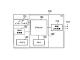
- FIG. 2 is a block diagram of the UE 100.
- the UE 100 includes a plurality of antennas 101, a radio transceiver 110, a user interface 120, a GNSS (Global Navigation Satellite System) receiver 130, a battery 140, a memory 150, and a processor 160.
- the memory 150 and the processor 160 constitute a control unit.
- the wireless transceiver 110 and the processor 160 constitute a transmission unit and a reception unit.
- the UE 100 may not have the GNSS receiver 130.
- the memory 150 may be integrated with the processor 160, and this set (that is, a chip set) may be used as the processor 160 '.
- the antenna 101 and the wireless transceiver 110 are used for transmitting and receiving wireless signals.
- the radio transceiver 110 converts the baseband signal (transmission signal) output from the processor 160 into a radio signal and transmits it from the antenna 101. Further, the radio transceiver 110 converts a radio signal received by the antenna 101 into a baseband signal (received signal) and outputs the baseband signal to the processor 160.
- the user interface 120 is an interface with a user who owns the UE 100, and includes, for example, a display, a microphone, a speaker, and various buttons.
- the user interface 120 receives an operation from the user and outputs a signal indicating the content of the operation to the processor 160.
- the GNSS receiver 130 receives a GNSS signal and outputs the received signal to the processor 160 in order to obtain location information indicating the geographical location of the UE 100.
- the battery 140 stores power to be supplied to each block of the UE 100.
- the memory 150 stores a program executed by the processor 160 and information used for processing by the processor 160.
- the processor 160 includes a baseband processor that modulates / demodulates and encodes / decodes a baseband signal, and a CPU (Central Processing Unit) that executes programs stored in the memory 150 and performs various processes. .
- the processor 160 may further include a codec that performs encoding / decoding of an audio / video signal.
- the processor 160 executes various processes and various communication protocols described later.
- FIG. 3 is a block diagram of the eNB 200.
- the eNB 200 includes a plurality of antennas 201, a radio transceiver 210, a network interface 220, a memory 230, and a processor 240.
- the memory 230 and the processor 240 constitute a control unit.
- the wireless transceiver 210 (and / or the network interface 220) and the processor 240 constitute a transmission unit and a reception unit.
- the memory 230 may be integrated with the processor 240, and this set (that is, a chip set) may be used as the processor.
- the antenna 201 and the wireless transceiver 210 are used for transmitting and receiving wireless signals.
- the radio transceiver 210 converts the baseband signal (transmission signal) output from the processor 240 into a radio signal and transmits it from the antenna 201.
- the radio transceiver 210 converts a radio signal received by the antenna 201 into a baseband signal (received signal) and outputs the baseband signal to the processor 240.
- the network interface 220 is connected to the neighboring eNB 200 via the X2 interface and is connected to the MME / S-GW 300 via the S1 interface.
- the network interface 220 is used for communication performed on the X2 interface and communication performed on the S1 interface.
- the memory 230 stores a program executed by the processor 240 and information used for processing by the processor 240.
- the processor 240 includes a baseband processor that performs modulation / demodulation and encoding / decoding of a baseband signal, and a CPU that executes a program stored in the memory 230 and performs various processes.
- the processor 240 executes various processes and various communication protocols described later.
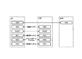
- FIG. 4 is a protocol stack diagram of a radio interface in the LTE system. As shown in FIG. 4, the radio interface protocol is divided into the first to third layers of the OSI reference model, and the first layer is a physical (PHY) layer.
- the second layer includes a MAC (Medium Access Control) layer, an RLC (Radio Link Control) layer, and a PDCP (Packet Data Convergence Protocol) layer.
- the third layer includes an RRC (Radio Resource Control) layer.
- the physical layer performs encoding / decoding, modulation / demodulation, antenna mapping / demapping, and resource mapping / demapping.
- User data and control information are transmitted between the physical layer of the UE 100 and the physical layer of the eNB 200 via a physical channel.
- the MAC layer performs data priority control, retransmission processing by hybrid ARQ (HARQ), random access procedure, and the like.
- User data and control information are transmitted between the MAC layer of the UE 100 and the MAC layer of the eNB 200 via a transport channel.
- the MAC layer of the eNB 200 includes a scheduler that determines an uplink / downlink transport format (transport block size, modulation / coding scheme (MCS)) and an allocation resource block to the UE 100.
- MCS modulation / coding scheme
- the RLC layer transmits data to the RLC layer on the receiving side using the functions of the MAC layer and the physical layer. Between the RLC layer of the UE 100 and the RLC layer of the eNB 200, user data and control information are transmitted via a logical channel.
- the PDCP layer performs header compression / decompression and encryption / decryption.
- the RRC layer is defined only in the control plane that handles control information. Control information (RRC message) for various settings is transmitted between the RRC layer of the UE 100 and the RRC layer of the eNB 200.
- the RRC layer controls the logical channel, the transport channel, and the physical channel according to establishment, re-establishment, and release of the radio bearer.
- RRC connection When there is a connection (RRC connection) between the RRC of the UE 100 and the RRC of the eNB 200, the UE 100 is in the RRC connected state, and otherwise, the UE 100 is in the RRC idle state.
- the NAS (Non-Access Stratum) layer located above the RRC layer performs session management and mobility management.
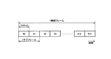
- FIG. 5 is a configuration diagram of a radio frame used in the LTE system.
- OFDMA Orthogonal Frequency Division Multiple Access
- SC-FDMA Single Carrier Division Multiple Access
- the radio frame is composed of 10 subframes arranged in the time direction.
- Each subframe is composed of two slots arranged in the time direction.
- the length of each subframe is 1 ms, and the length of each slot is 0.5 ms.
- Each subframe includes a plurality of resource blocks (RB) in the frequency direction and includes a plurality of symbols in the time direction.
- Each resource block includes a plurality of subcarriers in the frequency direction.
- One symbol and one subcarrier constitute one resource element (RE).
- a frequency resource can be specified by a resource block, and a time resource can be specified by a subframe (or slot).
- the D2D proximity service will be described below.
- the LTE system according to the first embodiment supports D2D proximity service.
- the D2D proximity service (D2D ProSe) is a service that enables direct UE-to-UE communication within a synchronized cluster composed of a plurality of synchronized UEs 100.
- the D2D proximity service includes a discovery procedure (Discovery) for discovering a nearby UE and D2D communication (Communication) that is direct UE-to-UE communication.
- D2D communication is also referred to as direct communication.
- a scenario in which all the UEs 100 forming the synchronous cluster are located in the cell coverage is referred to as “in coverage”.
- a scenario in which all UEs 100 forming a synchronous cluster are located outside cell coverage is referred to as “out of coverage”.
- a scenario in which some UEs 100 in the synchronization cluster are located within the cell coverage and the remaining UEs 100 are located outside the cell coverage is referred to as “partial coverage”.
- ENB200 becomes the D2D synchronization source within the coverage.
- the D2D asynchronous source synchronizes with the D2D synchronous source without transmitting the D2D synchronous signal.
- the eNB 200 that is the D2D synchronization source transmits D2D resource information indicating a radio resource (resource pool) that can be used for the D2D proximity service by a broadcast signal.
- the D2D resource information includes, for example, information indicating a resource pool for discovery procedure (Discovery resource information) and information indicating a resource pool for D2D communication (Communication resource information).
- UE100 which is D2D asynchronous origin performs a discovery procedure and D2D communication based on D2D resource information received from eNB200.
- the UE 100 In the case of out of coverage or partial coverage, the UE 100 becomes the D2D synchronization source. Outside the coverage, the UE 100 that is the D2D synchronization source transmits D2D resource information indicating radio resources (resource pools) that can be used for the D2D proximity service, for example, using a D2D synchronization signal.
- the D2D synchronization signal is a signal transmitted in a synchronization procedure for establishing synchronization between terminals.
- the D2D synchronization signal includes a D2D SS and a physical D2D synchronization channel (PD2DSCH).
- D2D SS is a signal that provides a time / frequency synchronization reference.
- PD2DSCH is a physical channel that carries more information than D2D SS.
- the PD2DSCH carries the above-described D2D resource information (Discovery resource information, Communication resource information). Alternatively, PD2DSCH may be unnecessary by associating D2D resource
- the discovery procedure is mainly used when D2D communication is performed by unicast.
- the UE 100 transmits a Discovery signal using one of the radio resources in the resource pool for the discovery procedure.
- the other UE 100 attempts to start D2D communication with the one UE 100, the other UE 100 scans the Discovery signal in the resource pool for the discovery procedure, and receives the Discovery signal.
- the Discovery signal may include information indicating a radio resource used by the one UE 100 for D2D communication.
- Inter-Cell Discovery a discovery procedure for a user terminal located in a certain cell (serving cell) to discover a neighboring terminal located in another cell (neighboring cell) is called an inter-cell discovery procedure (Inter-Cell Discovery).
- inter-cell D2D communication Inter-Cell Communication
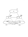
- FIG. 6 is a diagram illustrating an operating environment according to the first embodiment.
- eNB200 # 1 forms cell # 1
- eNB200 # 2 forms cell # 2.
- Cell # 1 and cell # 2 are adjacent to each other.
- the UE 100 # 1 is located in cell # 1.
- the UE 100 # 1 is in the RRC connected state or the RRC idle state in the cell # 1.
- the cell # 1 is a serving cell
- the cell # 2 is a neighboring cell.
- UE 100 # 2 is located in cell # 2.
- UE 100 # 2 is in the RRC connected state or the RRC idle state in cell # 2. Focusing on the UE 100 # 2, the cell # 1 is a neighboring cell, and the cell # 2 is a serving cell.
- a scenario is assumed in which the UE 100 # 1 performs an inter-cell discovery procedure with the UE 100 # 2 in such an operating environment.
- a scenario is assumed in which cell # 2 is not synchronized with cell # 1.
- cell # 2 is not synchronized with cell # 1
- UE 100 # 1 is asynchronous with UE 100 # 2, so UE 100 # 1 may fail even if it attempts an inter-cell discovery procedure with UE 100 # 2. High nature.
- FIG. 7 is a sequence diagram showing an operation according to the first embodiment.
- step S101 the eNB 200 # 1 transmits inter-cell synchronization information regarding whether or not the cell # 2 (adjacent cell) is synchronized with the cell # 1 (serving cell).
- the UE 100 # 1 receives inter-cell synchronization information from the eNB 200 # 1.
- Inter-cell synchronization information is transmitted by a broadcast signal.
- the inter-cell synchronization information may be transmitted by a unicast signal.
- the inter-cell synchronization information preferably includes the identifier of cell # 2.
- the inter-cell synchronization information may be included in the same message as the D2D resource information.
- step S102 the UE 100 # 1 determines whether to perform an inter-cell synchronization procedure (Inter-Cell Synchronization) for establishing synchronization with the UE 100 # 2 (neighboring terminal) based on the inter-cell synchronization information. . Specifically, when the cell # 2 is synchronized with the cell # 1, the UE 100 # 1 determines that the inter-cell synchronization procedure is unnecessary. On the other hand, when the cell # 2 is not synchronized with the cell # 1, the UE 100 # 1 determines to perform the inter-cell synchronization procedure.
- Inter-Cell Synchronization Inter-Cell Synchronization
- step S103 When cell # 2 is not synchronized with cell # 1 (step S102: NO), an inter-cell synchronization procedure is performed in step S103. There are two patterns for the inter-cell synchronization procedure. Details of each operation pattern will be described later.
- step S104 the UE 100 # 1 performs an inter-cell discovery procedure with the UE 100 # 2.
- the UE 100 # 1 receives the inter-cell synchronization information from the eNB 200 # 1 that forms the cell # 1 (serving cell).
- the UE 100 # 1 establishes synchronization with the UE 100 # 2 based on the inter-cell synchronization information before performing the inter-cell discovery procedure with the UE 100 # 2 (neighboring terminal) located in the cell # 2 (adjacent cell). It is determined whether or not to perform an inter-cell synchronization procedure.
- the UE 100 # 1 can confirm that the cell # 2 is not synchronized with the cell # 1 and perform the inter-cell synchronization procedure. Therefore, synchronization with the UE 100 # 2 can be established and the inter-cell discovery procedure can be appropriately performed.
- the UE 100 # 1 can omit the inter-cell synchronization procedure. Therefore, it is possible to suppress an increase in processing load and interference due to performing an unnecessary inter-cell synchronization procedure.
- UE100 # 1 transmits D2D SS (D2D synchronization signal) in the inter-cell synchronization procedure.
- UE100 # 2 which received D2D SS can synchronize with UE100 # 1. Therefore, synchronization is established between the UE 100 # 1 and the UE 100 # 2.
- UE100 # 2 which received D2D SS can synchronize with UE100 # 1. Therefore, synchronization is directly established between UE100 # 1 and UE100 # 2.
- the UE 100 # 1 may scan the D2D SS transmitted from the UE 100 # 2. If the D2D SS transmitted from the UE 100 # 2 cannot be detected as a result of the scan, the UE 100 # 1 may start transmitting the D2D SS. It is assumed that the D2D SS includes information indicating the serving cell of the UE that is the transmission source of the D2D SS.
- the D2D SS is used in the case of out-of-coverage or partial coverage, but in the first embodiment, the D2D SS is transmitted / received in the case within the coverage.
- the inter-cell synchronization information transmitted from the eNB 200 # 1 may include a 1-bit flag indicating whether or not the cell # 2 is synchronized with the cell # 1.
- the flag is associated with the identifier of cell # 2.
- UE 100 # 1 determines to perform an inter-cell synchronization procedure and starts transmission (or scanning) of D2D SS.
- the inter-cell synchronization information transmitted from the eNB 200 # 1 is information indicating the amount of synchronization deviation between the cell # 1 (serving cell) and the cell # 2 (adjacent cell).
- the information indicating the amount of synchronization deviation includes, for example, a radio frame offset value of cell # 2 with cell # 1 as a reference, a subframe offset value of cell # 2 with cell # 1 as a reference, and the like.
- the eNB 200 # 1 may transmit the inter-cell synchronization information for the cell # 2 only when the cell # 2 is not synchronized with the cell # 1. That is, eNB200 # 1 does not need to transmit inter-cell synchronization information for cell # 2 when cell # 2 is synchronized with cell # 1. In this case, the UE 100 # 1 determines to perform the inter-cell synchronization procedure when receiving the inter-cell synchronization information for the cell # 2 from the eNB 200 # 1.
- the eNB 200 # 1 may transmit inter-cell synchronization information for the cell # 2 even when the cell # 2 is synchronized with the cell # 1.
- the offset value indicating the amount of synchronization deviation is set to zero.
- the UE 100 # 1 determines to perform the inter-cell synchronization procedure when the inter-cell synchronization information including an offset value larger than zero is received.
- the UE 100 # 1 performs control to synchronize with the cell # 2 according to the amount of synchronization deviation. For example, adjustment of the transmission timing of the Discovery signal and / or adjustment of the reception timing of the Discovery signal is performed.
- the UE 100 # 1 performs control to synchronize with the cell # 2 according to the amount of synchronization deviation, whereby synchronization is established between the UE 100 # 1 and the UE 100 # 2.
- each UE 100 that performs the inter-cell synchronization procedure transmits and receives D2D SS within the coverage, and thus interference may increase due to the D2D SS. Therefore, in 2nd Embodiment, the increase in interference is suppressed by suppressing transmission of D2D SS in the operation pattern 1 of the synchronization procedure between cells mentioned above.
- FIG. 8 is a diagram illustrating an operating environment according to the second embodiment.
- UE100 # 1 and UE100 # 3 are located in the coverage of cell # 1. Moreover, UE100 # 2 is located in the coverage of cell # 2. Each of UE100 # 1 to UE100 # 3 is UE100 that performs an inter-cell synchronization procedure to perform an inter-cell discovery procedure.
- the UE100 # 3 is located in the vicinity of UE100 # 1 and transmits D2D SS.
- the D2D SS includes information indicating the serving cell of the transmission source UE.
- Each of UE100 # 1 and UE100 # 2 receives D2D SS from UE100 # 3.
- the UE 100 # 2 establishes synchronization with the UE 100 # 3 using the D2D SS.
- UE 100 # 1 and UE 100 # 3 located in the same cell are synchronized with each other, UE 100 # 2 establishes synchronization with UE 100 # 3 and also establishes synchronization with UE 100 # 1. It will be done. Therefore, UE100 # 1 does not need to transmit D2D SS.
- the UE 100 # 1 exists in the cell # 1 (serving cell) before performing the inter-cell discovery procedure with the UE 100 # 2 (neighboring terminal) located in the cell # 2 (adjacent cell).
- Scan D2D SS transmitted from UE100 # 3 (other UE).
- UE100 # 1 stops transmission of D2D SS from self-UE100 # 1 based on having detected D2D SS transmitted from UE100 # 3 located in cell # 1.
- the UE 100 # 1 detects the D2D SS transmitted from the UE 100 # 3 located in the cell # 1 and the received level of the detected D2D SS exceeds the threshold, the UE 100 # 1 It is preferable to stop transmission of D2D SS.
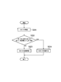
- FIG. 9 is a flowchart showing the operation of the UE 100 # 1 according to the second embodiment. For example, the UE 100 # 1 starts this flow when it is determined to perform the inter-cell discovery procedure.
- step S201 the UE 100 # 1 scans the D2D SS and measures the reception level of the received D2D SS.
- step S202 the UE 100 # 1 determines whether or not the serving cell identifier included in the D2D SS matches the cell identifier of the cell # 1. If they match, the UE 100 # 1 determines whether or not the reception level of the D2D SS exceeds a threshold value.
- the UE 100 # 1 starts (or continues) the transmission of the D2D SS in the step S203. On the other hand, if “YES” in the step S202, the UE 100 # 1 stops transmitting the D2D SS in the step S204.
- the UE 100 # 1 located in the cell # 1 detects the D2D SS transmitted from another UE located in the cell # 1 in the inter-cell synchronization procedure, based on the detection of the D2D SS. Stop sending D2D SS from. Thereby, transmission of D2D SS can be suppressed.
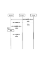
- FIG. 10 is a sequence diagram showing an operation according to the modified example of the second embodiment.
- UE100 # 1 and UE100 # 3 are located in cell # 1 formed by eNB200 # 1.
- the UE 100 # 3 transmits an inquiry regarding whether or not to transmit the D2D SS to the eNB 200 # 1.
- the inquiry may include geographical location information of the UE 100 # 3.
- eNB200 # 1 judges whether transmission of D2D SS is permitted with respect to the inquiry from UE100 # 3.
- the description will be made on the assumption that transmission of the D2D SS is permitted to the UE 100 # 3.
- the eNB 200 # 1 stores information on the UE 100 # 3 that is permitted to transmit the D2D SS.
- step S302 the eNB 200 # 1 notifies the UE 100 # 3 of transmission permission of the D2D SS.
- UE100 # 3 will start transmission of D2D SS, if transmission of D2D SS is permitted.
- step S303 the UE 100 # 1 transmits an inquiry regarding whether or not the D2D SS can be transmitted to the eNB 200 # 1.
- the inquiry may include geographical location information of the UE 100 # 1.
- step S304 the eNB 200 # 1 determines whether to permit transmission of the D2D SS in response to the inquiry from the UE 100 # 1.
- the eNB 200 # 1 has already permitted the UE 100 # 3 to transmit the D2D SS, that is, since the UE 100 # 3 is transmitting the D2D SS, the eNB 200 # 1 determines that the UE 100 # 1 does not permit the transmission of the D2D SS. Also good.
- the eNB 200 # 1 permits the UE 100 # 3 to transmit the D2D SS, and when the UE 100 # 3 is estimated to exist in the vicinity of the UE 100 # 1, the eNB 200 # 1 transmits the D2D SS by the UE 100 # 1. You may decide not to allow it. In this case, the eNB 200 # 1 may determine whether the UE 100 # 3 exists in the vicinity of the UE 100 # 1 based on the geographical location information included in the inquiry. Alternatively, when the eNB 200 # 1 manages the path loss value, the uplink transmission power value, or the timing advance (TA) value of each UE 100, the path loss value, the uplink transmission power value, Alternatively, the determination may be made based on the TA value.
- TA timing advance
- step S305 the eNB 200 # 1 notifies the UE 100 # 1 of transmission prohibition (rejection) of the D2D SS.
- the UE 100 # 1 does not start transmission of D2D SS because transmission of D2D SS is not permitted.
- the UE 100 that stops the transmission of the D2D SS inquires or notifies the eNB 200 # 1 to that effect.
- the LTE system is described as an example of the mobile communication system.
- the present invention is not limited to the LTE system, and the present invention may be applied to a system other than the LTE system.
- RAN 2 agreed on the D2D reception Discovery resource pool as follows.
- ENB may provide D2D reception Discovery resources in SIB. These resources may cover resources used for D2D transmission in the own cell and resources used in neighboring cells. (Details will be examined in the future)
- RAN1 agreed as follows.
- the eNB may provide the SIB with (multiple) radio resource pools for D2D UEs for discovery reception for type 2B. It will be examined in the future (FFS) whether it is a common reception pool (several) or a different reception pool for Type 1 and Type 2B Discovery. The UE does not need to decode neighboring cell SIBs.
- a resource hopping mechanism can be applied after resource allocation by the eNB. Details of the resource hopping mechanism will be examined in the future.
- Synchronous deployment (Synchronous deployment)
- the D2D UE can perform transmission / reception of inter-cell Discovery by referring to the synchronization signal transmitted from the serving cell. Therefore, the serving cell does not need to transmit additional information other than the reception resource pool.
- Synchronous deployment can be achieved by OAM and eNB implementations. For example, synchronous deployment may be envisioned within each MBSFN region.
- Asynchronous deployment In the asynchronous deployment, since the serving cell is not synchronized with the adjacent cell, the D2D UE of the serving cell needs to be synchronized with the D2D UE of the adjacent cell before performing transmission / reception of inter-cell Discovery.
- inter-cell Discovery should also be considered for both types of deployments.
- a common scheme for performing inter-cell discovery should be introduced in both synchronous and asynchronous deployments. It is assumed that the scheme can be classified based on whether the D2D UE performs direct synchronization with other D2D UEs for inter-cell discovery.
- the in-coverage D2D UE transmits the D2D SS or receives the D2D SS transmitted by the D2D UE of the adjacent cell before performing the inter-cell Discovery.
- the in-coverage D2D UE transmits the D2D SS or receives the D2D SS transmitted by the D2D UE of the adjacent cell before performing the inter-cell Discovery.
- this scheme it is assumed that direct synchronization with other D2D UEs is performed, so it does not matter whether the neighboring cell is synchronized with the serving cell. This scheme is therefore applicable for both synchronous and asynchronous deployments.
- the in-coverage D2D UE transmits the D2D SS before transmitting the Discovery signal to the D2D UE in the neighboring cell.
- the in-coverage D2D UE monitors the D2D SS transmitted by the D2D UE in the neighboring cell before receiving the Discovery signal from the D2D UE in the neighboring cell.
- One of the disadvantages of this scheme is increased interference between D2D SS transmissions in NW coverage. Therefore, further improvements are needed to minimize the number of D2D UEs that are transmitting D2D SSs for inter-cell Discovery.
- the serving cell in order to perform inter-cell Discovery for asynchronous deployment, the serving cell should inform the in-coverage D2D UE of the timing of the neighboring cell, so the in-coverage D2D UE Regardless of whether it is synchronized or not, it is possible to transmit and receive inter-cell Discovery without transmitting and receiving D2D SS. It is assumed that the neighbor cell timing as well as the neighbor cell receive resource pool can be provided to the serving cell by OAM. Therefore, the serving cell should provide timing information to the D2D UE as well as the reception resource pool of neighboring cells.
- RAN2 should consider which option should be adopted for inter-cell D2D Discovery.
- Proposal 1 RAN2 should consider which option should be adopted for inter-cell D2D Discovery.
- Proposal 2 If option 2 is agreed, the serving cell should provide timing information as well as a receiving resource pool.
- the present invention is useful in the communication field.
Landscapes
- Engineering & Computer Science (AREA)
- Computer Networks & Wireless Communication (AREA)
- Signal Processing (AREA)
- Databases & Information Systems (AREA)
- Quality & Reliability (AREA)
- Physics & Mathematics (AREA)
- Electromagnetism (AREA)
- Computer Security & Cryptography (AREA)
- Mobile Radio Communication Systems (AREA)
Abstract
Description
第1実施形態に係るユーザ端末は、D2D近傍サービスをサポートする移動通信システムにおいて、サービングセルに在圏するユーザ端末である。前記ユーザ端末は、前記サービングセルを形成する基地局から、隣接セルが前記サービングセルと同期しているか否かに関するセル間同期情報を受信する受信部と、前記隣接セルに在圏する近傍端末とのセル間発見手順又は当該近傍端末とのセル間D2D通信を行う前に、前記セル間同期情報に基づいて、前記近傍端末との同期を確立するためのセル間同期手順を行うか否かを判断する制御部と、を備える。
以下において、3GPP規格に基づく移動通信システムであるLTEシステムに本発明を適用する場合の実施形態を説明する。
先ず、第1実施形態に係るLTEシステムのシステム構成について説明する。図1は、第1実施形態に係るLTEシステムの構成図である。
以下において、D2D近傍サービスについて説明する。第1実施形態に係るLTEシステムは、D2D近傍サービスをサポートする。
以下において、第1実施形態に係る動作環境について説明する。図6は、第1実施形態に係る動作環境を示す図である。
以下において、第1実施形態に係る動作について説明する。
図7は、第1実施形態に係る動作を示すシーケンス図である。
次に、セル間同期手順の動作パターン1について説明する。
次に、セル間同期手順の動作パターン2について説明する。
第2実施形態について、第1実施形態との相違点を主として説明する。第2実施形態では、上述したセル間同期手順の動作パターン1が適用されるケースを想定する。
以下において、第2実施形態に係る動作環境について説明する。図8は、第2実施形態に係る動作環境を示す図である。
以下において、第2実施形態に係る動作について説明する。
上述した第2実施形態では、UE主導でD2D SSの送信を制御していた。しかしながら、eNB主導でD2D SSの送信を制御してもよい。第2実施形態の変更例では、eNB200の許可を得なければD2D SSを送信できないケースを想定する。但し、基本的な考え方は第2実施形態と同様である。
上述した各実施形態では、UE100#1がUE100#2とのセル間発見手順を行うシナリオを想定していた。しかしながら、UE100#1がUE100#2とのセル間発見手順を行うことなく、UE100#1がUE100#2とのセル間D2D通信を行うシナリオにも本発明を適用可能である。すなわち、上述した各実施形態に係る動作における「セル間発見手順」を「セル間D2D通信」と読み替えることが可能である。
以下において、実施形態の補足事項について付記する。
セル間発見手順(セル間Discovery)に関して、RAN2ではD2D受信Discoveryリソースプールに関して以下の通り合意された。
サービングセルと隣接セルとの間の同期に関して、以下の2つの配備が検討された。
同期配備では、サービングセルが隣接セルと同期しているため、D2D UEは、サービングセルから送信された同期信号を参照することによって、セル間Discoveryの送受信を実施できる。したがって、サービングセルは、受信リソースプール以外の追加の情報を送信する必要がない。同期配備は、OAM及びeNB実装によって達成できる。例えば、同期配備は、各MBSFN領域内で想定されてもよい。
非同期配備では、サービングセルが隣接セルと同期していないため、サービングセルのD2D UEは、セル間Discoveryの送受信を行う前に、隣接セルのD2D UEと同期する必要がある。
直接的同期では、隣接セルのD2D UEと同期するために、セル間Discoveryを行う前に、カバレッジ内D2D UEがD2D SSを送信、又は隣接セルのD2D UEにより送信されたD2D SSを受信する。このスキームでは、他のD2D UEと直接的同期を行うことが想定されているので、隣接セルが、サービングセルと同期しているかどうかは問題ではない。したがって、このスキームは、同期及び非同期配備の両方に対して適用可能である。
このスキームでは、セル間Discoveryを非同期配備に対して行うために、サービングセルは、カバレッジ内D2D UEに対して隣接セルのタイミングを通知するべきであるので、カバレッジ内D2D UEは、隣接セルがサービングセルと同期しているか否かに拘らず、D2D SSを送受信せずに、セル間Discoveryの送受信を行うことができる。隣接セルのタイミング並びに隣接セルの受信リソースプールが、OAMによりサービングセルへ提供可能であると想定される。したがって、サービングセルは、D2D UEへタイミング情報並びに隣接セルの受信リソースプールを提供するべきである。
米国仮出願第61/990951号(2014年5月9日出願)の全内容が参照により本願明細書に組み込まれている。
Claims (11)
- D2D近傍サービスをサポートする移動通信システムにおいて、サービングセルに在圏するユーザ端末であって、
前記サービングセルを形成する基地局から、隣接セルが前記サービングセルと同期しているか否かに関するセル間同期情報を受信する受信部と、
前記隣接セルに在圏する近傍端末とのセル間発見手順又は当該近傍端末とのセル間D2D通信を行う前に、前記セル間同期情報に基づいて、前記近傍端末との同期を確立するためのセル間同期手順を行うか否かを判断する制御部と、
を備えることを特徴とするユーザ端末。 - 前記セル間同期手順において、前記制御部は、前記近傍端末から送信されるD2D同期信号をスキャンすることを特徴とする請求項1に記載のユーザ端末。
- 前記セル間同期情報は、前記サービングセルと前記隣接セルとの間の同期ずれ量を示す情報を含むことを特徴とする請求項1に記載のユーザ端末。
- 前記セル間同期手順において、前記制御部は、前記同期ずれ量に応じて前記隣接セルに同期する制御を行うことを特徴とする請求項3に記載のユーザ端末。
- 前記セル間同期情報は、前記隣接セルのセル識別子を含むことを特徴とする請求項1に記載のユーザ端末。
- 前記制御部は、前記セル間同期情報に基づいて前記同期を確立することにより、前記セル間発見手順におけるDiscovery信号を前記近傍端末から受信する処理を行うことを特徴とする請求項2に記載のユーザ端末。
- D2D近傍サービスをサポートする移動通信システムにおいて、サービングセルに在圏するユーザ端末であって、
前記サービングセルを形成する基地局から、D2D同期信号の送信を指示する情報を受信した場合、前記D2D同期信号を送信する処理を行う制御部を備えることを特徴とするユーザ端末。 - D2D近傍サービスをサポートする移動通信システムにおいて、サービングセルに在圏するユーザ端末であって、
隣接セルに在圏する近傍端末とのセル間発見手順又は当該近傍端末とのセル間D2D通信を行う前に、当該近傍端末との同期を確立するためのD2D同期信号を送信する送信部と、
前記サービングセルに在圏する他のユーザ端末から送信されるD2D同期信号を検知したことに基づいて、前記送信部からの前記D2D同期信号の送信を中止する制御を行う制御部と、
を備えることを特徴とするユーザ端末。 - 前記制御部は、前記サービングセルに在圏する他のユーザ端末から送信されるD2D同期信号を検知し、かつ、当該検知したD2D同期信号の受信レベルが閾値を超える場合に、前記送信部からの前記D2D同期信号の送信を中止する制御を行うことを特徴とする請求項8に記載のユーザ端末。
- D2D近傍サービスをサポートする移動通信システムにおいて、ユーザ端末が在圏しているサービングセルを形成する基地局であって、
前記ユーザ端末から、近傍端末との同期を確立するためのD2D同期信号の送信可否に関する問い合せを受信する受信部と、
前記サービングセルに在圏する他のユーザ端末に前記D2D同期信号の送信を許可しているか否かに基づいて、前記ユーザ端末による前記D2D同期信号の送信を許可するか否かを判断する制御部と、
を備えることを特徴とする基地局。 - 前記制御部は、前記他のユーザ端末に前記D2D同期信号の送信を許可しており、かつ、前記ユーザ端末の近傍に前記他のユーザ端末が存在すると推定される場合に、前記ユーザ端末による前記D2D同期信号の送信を許可しないと判断することを特徴とする請求項10に記載の基地局。
Priority Applications (5)
| Application Number | Priority Date | Filing Date | Title |
|---|---|---|---|
| EP15788952.8A EP3142451B1 (en) | 2014-05-09 | 2015-05-08 | User terminal and base station |
| JP2016517933A JP6142082B2 (ja) | 2014-05-09 | 2015-05-08 | ユーザ端末、プロセッサ、及び基地局 |
| US15/049,905 US9578614B2 (en) | 2014-05-09 | 2016-02-22 | User terminal and base station |
| US15/050,976 US9668231B2 (en) | 2014-05-09 | 2016-02-23 | User terminal and base station |
| US15/416,956 US10045317B2 (en) | 2014-05-09 | 2017-01-26 | User terminal and base station |
Applications Claiming Priority (2)
| Application Number | Priority Date | Filing Date | Title |
|---|---|---|---|
| US201461990951P | 2014-05-09 | 2014-05-09 | |
| US61/990,951 | 2014-05-09 |
Related Child Applications (2)
| Application Number | Title | Priority Date | Filing Date |
|---|---|---|---|
| US15/049,905 Continuation US9578614B2 (en) | 2014-05-09 | 2016-02-22 | User terminal and base station |
| US15/050,976 Continuation US9668231B2 (en) | 2014-05-09 | 2016-02-23 | User terminal and base station |
Publications (1)
| Publication Number | Publication Date |
|---|---|
| WO2015170730A1 true WO2015170730A1 (ja) | 2015-11-12 |
Family
ID=54392579
Family Applications (1)
| Application Number | Title | Priority Date | Filing Date |
|---|---|---|---|
| PCT/JP2015/063262 Ceased WO2015170730A1 (ja) | 2014-05-09 | 2015-05-08 | ユーザ端末及び基地局 |
Country Status (4)
| Country | Link |
|---|---|
| US (3) | US9578614B2 (ja) |
| EP (1) | EP3142451B1 (ja) |
| JP (2) | JP6142082B2 (ja) |
| WO (1) | WO2015170730A1 (ja) |
Cited By (2)
| Publication number | Priority date | Publication date | Assignee | Title |
|---|---|---|---|---|
| JP2015023472A (ja) * | 2013-07-19 | 2015-02-02 | 株式会社Nttドコモ | ユーザ装置、基地局、発見信号受信方法、及び発見信号送信方法 |
| EP3457745A4 (en) * | 2016-05-13 | 2019-04-17 | Huawei Technologies Co., Ltd. | RESOURCE ASSOCIATION METHOD AND ASSOCIATED DEVICE |
Families Citing this family (10)
| Publication number | Priority date | Publication date | Assignee | Title |
|---|---|---|---|---|
| US20160029334A1 (en) * | 2014-07-25 | 2016-01-28 | Electronics And Telecommunications Research Institute | Method and apparatus for synchronizing networks among heterogeneous wireless operators |
| WO2016018075A1 (ko) * | 2014-07-29 | 2016-02-04 | 엘지전자 주식회사 | 무선 통신 시스템에서 d2d(device-to-device) 통신을 위한 신호 송수신 방법 및 이를 위한 장치 |
| JP6311515B2 (ja) * | 2014-07-30 | 2018-04-18 | ソニー株式会社 | 装置 |
| EP3200367B1 (en) | 2014-09-24 | 2021-03-10 | LG Electronics Inc. | Method for transmitting d2d signal and terminal therefor |
| US10034322B2 (en) * | 2015-02-06 | 2018-07-24 | Samsung Electronics Co., Ltd. | Method and apparatus for transmitting and receiving signal in communication system supporting device to device scheme |
| US10172107B2 (en) * | 2016-03-30 | 2019-01-01 | Lg Electronics Inc. | Method of transmitting SLSS by V2V terminal |
| CN109041105B (zh) * | 2017-06-09 | 2020-10-16 | 维沃移动通信有限公司 | 邻小区信息的发送方法、邻小区信息的处理方法及设备 |
| EP3860253A4 (en) * | 2018-09-27 | 2022-05-11 | Ntt Docomo, Inc. | USER DEVICE |
| US11671930B2 (en) * | 2019-05-29 | 2023-06-06 | Qualcomm Incorporated | Early termination of synchronization procedure |
| US11540224B2 (en) * | 2020-02-11 | 2022-12-27 | Qualcomm Incorporated | Vehicle-to-everything (V2X) inter-user equipment (UE) coordination |
Family Cites Families (17)
| Publication number | Priority date | Publication date | Assignee | Title |
|---|---|---|---|---|
| WO2011147462A1 (en) * | 2010-05-28 | 2011-12-01 | Nokia Siemens Networks Oy | Method and apparatus for device-to-device communications |
| WO2012082024A1 (en) * | 2010-12-13 | 2012-06-21 | Telefonaktiebolaget L M Ericsson (Publ) | Methods and user equipments for device to device communication |
| CN103999489A (zh) * | 2011-12-08 | 2014-08-20 | 诺基亚通信公司 | D2d群集中的设备的网络同步 |
| US20140094212A1 (en) * | 2012-09-28 | 2014-04-03 | Electronics And Telecommunications Research Institute | Method of device to device discovery and apparatus thereof |
| US11496948B2 (en) * | 2012-10-19 | 2022-11-08 | Samsung Electronics Co., Ltd. | System and method for ad-hoc/network assisted device discovery protocol for device to device communications |
| US9072027B2 (en) * | 2012-12-07 | 2015-06-30 | Alcatel Lucent | Methods and apparatuses for facilitating D2D bearer switching |
| CN103974225B (zh) * | 2013-02-01 | 2018-03-13 | 财团法人工业技术研究院 | 通讯装置、装置对装置通讯系统及其无线通信方法 |
| WO2014173443A1 (en) * | 2013-04-24 | 2014-10-30 | Nokia Solutions And Networks Oy | Mobility management for device-to-device communications |
| EP2992626A4 (en) * | 2013-05-01 | 2016-12-28 | Samsung Electronics Co Ltd | METHOD AND DEVICE FOR D2D COMMUNICATION |
| US20150056982A1 (en) * | 2013-08-22 | 2015-02-26 | Telefonaktiebolaget L M Ericsson (Publ) | Methods and Network Nodes for Management of Resources |
| US9392629B2 (en) * | 2013-09-10 | 2016-07-12 | Electronics And Telecommunications Research Institute | Method for setting synchronization between device-to-device communication terminals based on cellular communication system |
| WO2015054903A1 (zh) * | 2013-10-18 | 2015-04-23 | 华为技术有限公司 | D2d终端间的初始同步方法及设备 |
| CN105934921B (zh) * | 2013-10-31 | 2019-10-18 | 华为技术有限公司 | 用于设备到设备同步的系统和方法 |
| US9516551B2 (en) * | 2014-01-31 | 2016-12-06 | Telefonaktiebolaget Lm Ericsson (Publ) | Interference mitigation of D2D communications in different coverage scenarios |
| WO2015142895A1 (en) * | 2014-03-18 | 2015-09-24 | Sharp Laboratories Of America, Inc. | Device-to device communications apparatus and methods |
| CN106575994B (zh) * | 2014-03-18 | 2020-12-11 | 夏普株式会社 | 无线接入节点及其方法、无线终端及其方法 |
| US10660146B2 (en) * | 2014-03-21 | 2020-05-19 | Samsung Electronics Co., Ltd. | Methods and apparatus for device to device synchronization priority |
-
2015
- 2015-05-08 EP EP15788952.8A patent/EP3142451B1/en active Active
- 2015-05-08 JP JP2016517933A patent/JP6142082B2/ja active Active
- 2015-05-08 WO PCT/JP2015/063262 patent/WO2015170730A1/ja not_active Ceased
-
2016
- 2016-02-22 US US15/049,905 patent/US9578614B2/en active Active
- 2016-02-23 US US15/050,976 patent/US9668231B2/en active Active
-
2017
- 2017-01-26 US US15/416,956 patent/US10045317B2/en active Active
- 2017-05-08 JP JP2017092578A patent/JP6224861B2/ja active Active
Non-Patent Citations (7)
| Title |
|---|
| CATT: "Discussion on inter- cell coordination for D2D", R3-140066, 3GPP, XP050738507 * |
| ERICSSON: "Synchronization Procedures for D2D Discovery and Communication", RL-141381, 3GPP, 21 March 2014 (2014-03-21), XP050787052 * |
| NOKIA ET AL.: "D2D Synchronization - Out of network coverage/partial network coverage", R1- 133496, 3GPP, 10 August 2013 (2013-08-10), XP050716603 * |
| NOKIA ET AL.: "On D2D synchronization design", R1- 140571, 3GPP, 31 January 2014 (2014-01-31), XP050736098 * |
| NTT DOCOMO, INC.: "Resource allocation for inter- cell D2D discovery", RL-134503, 3GPP, 28 September 2013 (2013-09-28), XP050717605 * |
| See also references of EP3142451A4 * |
| SONY: "Remaining issues in D2D synchronization", R1-140588, 3GPP, 1 February 2014 (2014-02-01), XP050736115 * |
Cited By (3)
| Publication number | Priority date | Publication date | Assignee | Title |
|---|---|---|---|---|
| JP2015023472A (ja) * | 2013-07-19 | 2015-02-02 | 株式会社Nttドコモ | ユーザ装置、基地局、発見信号受信方法、及び発見信号送信方法 |
| EP3457745A4 (en) * | 2016-05-13 | 2019-04-17 | Huawei Technologies Co., Ltd. | RESOURCE ASSOCIATION METHOD AND ASSOCIATED DEVICE |
| US11082965B2 (en) | 2016-05-13 | 2021-08-03 | Huawei Technologies Co., Ltd. | Resource allocation method and relevant device |
Also Published As
| Publication number | Publication date |
|---|---|
| JP6142082B2 (ja) | 2017-06-07 |
| JP2017169219A (ja) | 2017-09-21 |
| JPWO2015170730A1 (ja) | 2017-04-20 |
| US10045317B2 (en) | 2018-08-07 |
| EP3142451A4 (en) | 2018-01-10 |
| US20160174175A1 (en) | 2016-06-16 |
| JP6224861B2 (ja) | 2017-11-01 |
| EP3142451A1 (en) | 2017-03-15 |
| US20170142673A1 (en) | 2017-05-18 |
| EP3142451B1 (en) | 2020-03-25 |
| US9578614B2 (en) | 2017-02-21 |
| US9668231B2 (en) | 2017-05-30 |
| US20160174176A1 (en) | 2016-06-16 |
Similar Documents
| Publication | Publication Date | Title |
|---|---|---|
| JP6224861B2 (ja) | ユーザ端末、プロセッサ、及び方法 | |
| US10097966B2 (en) | Communication control method and user terminal for selecting synchronization reference of device-to-device (D2D) | |
| JP6328132B2 (ja) | 移動通信システム及びユーザ端末 | |
| JP6026549B2 (ja) | 移動通信システム、基地局及びユーザ端末 | |
| JP6313485B2 (ja) | ユーザ端末、移動通信方法及びプロセッサ | |
| WO2014034573A1 (ja) | 基地局、ユーザ端末及びプロセッサ | |
| JP6499166B2 (ja) | 通信制御方法、ユーザ端末及び基地局 | |
| JP6475745B2 (ja) | 基地局及びユーザ端末 | |
| JP2018152888A (ja) | 通信制御方法、ユーザ端末及びプロセッサ | |
| JPWO2014069222A1 (ja) | 移動通信システム、ユーザ端末、基地局、プロセッサ及び通信制御方法 | |
| JPWO2015141847A1 (ja) | 通信制御方法及び基地局 | |
| JP6302129B1 (ja) | 基地局及びプロセッサ | |
| JP6106286B2 (ja) | ユーザ端末及びプロセッサ | |
| WO2015170727A1 (ja) | ユーザ端末及び通信制御方法 | |
| WO2014157397A1 (ja) | 通信制御方法、ユーザ端末、及び基地局 |
Legal Events
| Date | Code | Title | Description |
|---|---|---|---|
| 121 | Ep: the epo has been informed by wipo that ep was designated in this application |
Ref document number: 15788952 Country of ref document: EP Kind code of ref document: A1 |
|
| ENP | Entry into the national phase |
Ref document number: 2016517933 Country of ref document: JP Kind code of ref document: A |
|
| REEP | Request for entry into the european phase |
Ref document number: 2015788952 Country of ref document: EP |
|
| WWE | Wipo information: entry into national phase |
Ref document number: 2015788952 Country of ref document: EP |
|
| NENP | Non-entry into the national phase |
Ref country code: DE |