WO2015170767A1 - 移動通信システム、ユーザ端末及びプロセッサ - Google Patents
移動通信システム、ユーザ端末及びプロセッサ Download PDFInfo
- Publication number
- WO2015170767A1 WO2015170767A1 PCT/JP2015/063377 JP2015063377W WO2015170767A1 WO 2015170767 A1 WO2015170767 A1 WO 2015170767A1 JP 2015063377 W JP2015063377 W JP 2015063377W WO 2015170767 A1 WO2015170767 A1 WO 2015170767A1
- Authority
- WO
- WIPO (PCT)
- Prior art keywords
- discovery
- discovery resource
- resource pool
- user terminal
- processor
- Prior art date
- Legal status (The legal status is an assumption and is not a legal conclusion. Google has not performed a legal analysis and makes no representation as to the accuracy of the status listed.)
- Ceased
Links
Images


Classifications
-
- H—ELECTRICITY
- H04—ELECTRIC COMMUNICATION TECHNIQUE
- H04W—WIRELESS COMMUNICATION NETWORKS
- H04W8/00—Network data management
- H04W8/005—Discovery of network devices, e.g. terminals
-
- H—ELECTRICITY
- H04—ELECTRIC COMMUNICATION TECHNIQUE
- H04W—WIRELESS COMMUNICATION NETWORKS
- H04W72/00—Local resource management
- H04W72/04—Wireless resource allocation
-
- H—ELECTRICITY
- H04—ELECTRIC COMMUNICATION TECHNIQUE
- H04W—WIRELESS COMMUNICATION NETWORKS
- H04W8/00—Network data management
-
- H—ELECTRICITY
- H04—ELECTRIC COMMUNICATION TECHNIQUE
- H04W—WIRELESS COMMUNICATION NETWORKS
- H04W92/00—Interfaces specially adapted for wireless communication networks
- H04W92/16—Interfaces between hierarchically similar devices
- H04W92/18—Interfaces between hierarchically similar devices between terminal devices
Definitions
- the present application relates to a mobile communication system, a user terminal, and a processor that support D2D communication that is direct communication between terminals.
- 3GPP 3rd Generation Partnership Project
- D2D Device to Device
- the D2D proximity service (D2D ProSe) is a service that enables direct terminal-to-terminal communication within a synchronous cluster composed of a plurality of synchronized user terminals.
- the D2D proximity service includes a D2D discovery procedure (Discovery) for discovering a nearby terminal and D2D communication (Communication) which is direct inter-terminal communication.
- the D2D discovery procedure includes a first discovery method (Type 1 discovery) in which radio resources that are not uniquely allocated to the UE 100 are used for transmission of Discovery signals, and radio resources that are uniquely allocated to each UE 100 are Discovery signals. There is a second discovery method (Type 2 discovery) that is used for transmission.
- Type 1 discovery a first discovery method in which radio resources that are not uniquely allocated to the UE 100 are used for transmission of Discovery signals, and radio resources that are uniquely allocated to each UE 100 are Discovery signals.
- the discovery resource pool in which the first discovery resource and the second discovery resource are arranged is provided in a frequency band for uplink cellular communication.
- an object of the present application is to make it possible to appropriately arrange a discovery resource pool provided in a frequency band for uplink cellular communication.
- a discovery resource pool in which discovery resources for a D2D discovery procedure for discovering nearby terminals are arranged is provided in a frequency band for uplink cellular communication.
- a first discovery resource pool in which a first discovery resource that is not uniquely assigned to a user terminal is arranged and a second discovery resource that is uniquely assigned to each user terminal is arranged in a second And a discovery resource pool.
- the first discovery resource pool and the second discovery resource pool are alternately arranged in the time direction at a time interval shorter than the retransmission interval of the uplink cellular communication.
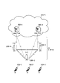
- FIG. 1 is a configuration diagram of an LTE system according to the embodiment.
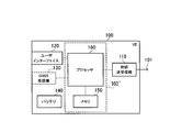
- FIG. 2 is a block diagram of the UE according to the embodiment.
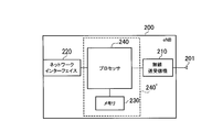
- FIG. 3 is a block diagram of the eNB according to the embodiment.
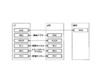
- FIG. 4 is a protocol stack diagram according to the embodiment.
- FIG. 5 is a configuration diagram of a radio frame according to the embodiment.
- FIG. 6 is a diagram for explaining the discovery resource pool according to the embodiment.
- FIG. 7 is a diagram for explaining the discovery resource pool (part 1) according to the supplementary notes.
- FIG. 8 is a diagram for explaining the discovery resource pool (part 2) according to the supplementary notes.
- a discovery resource pool in which discovery resources for a D2D discovery procedure for discovering neighboring terminals are arranged in a frequency band for uplink cellular communication.
- a first discovery resource pool in which a first discovery resource that is not uniquely assigned to a user terminal is arranged, and a second discovery resource that is uniquely assigned to each user terminal is arranged in a second.
- a discovery resource pool in which The first discovery resource pool and the second discovery resource pool are alternately arranged in the time direction at a time interval shorter than the retransmission interval of the uplink cellular communication.
- the discovery resource pool and the radio resource area for uplink cellular communication are alternately arranged in the time direction.
- the user terminal includes a control unit that performs a D2D discovery procedure using a discovery resource for a D2D discovery procedure for discovering a neighboring terminal.
- a discovery resource pool in which the discovery resources are arranged is provided in a frequency band for uplink cellular communication.
- a first discovery resource pool in which a first discovery resource that is not uniquely assigned to a user terminal is arranged, and a second discovery resource that is uniquely assigned to each user terminal is arranged in a second.
- a discovery resource pool is alternately arranged in the time direction at a time interval shorter than the retransmission interval of the uplink cellular communication.
- the processor is provided in a user terminal.
- the processor executes a process of performing the D2D discovery procedure using the discovery resource for the D2D discovery procedure for discovering the neighboring terminal.
- a discovery resource pool in which the discovery resources are arranged is provided in a frequency band for uplink cellular communication.
- a first discovery resource pool in which a first discovery resource that is not uniquely assigned to a user terminal is arranged, and a second discovery resource that is uniquely assigned to each user terminal is arranged in a second.
- a discovery resource pool is alternately arranged in the time direction at a time interval shorter than the retransmission interval of the uplink cellular communication.
- FIG. 1 is a configuration diagram of an LTE system according to the embodiment.
- the LTE system according to the embodiment includes a UE (User Equipment) 100, an E-UTRAN (Evolved-UMTS Terrestrial Radio Access Network) 10, and an EPC (Evolved Packet Core) 20.
- UE User Equipment
- E-UTRAN Evolved-UMTS Terrestrial Radio Access Network
- EPC Evolved Packet Core
- the UE 100 corresponds to a user terminal.
- the UE 100 is a mobile communication device, and performs wireless communication with a connection destination cell (serving cell).
- the configuration of the UE 100 will be described later.
- the E-UTRAN 10 corresponds to a radio access network.
- the E-UTRAN 10 includes an eNB 200 (evolved Node-B).
- the eNB 200 corresponds to a base station.
- the eNB 200 is connected to each other via the X2 interface. The configuration of the eNB 200 will be described later.
- the eNB 200 manages one or a plurality of cells and performs radio communication with the UE 100 that has established a connection with the own cell.
- the eNB 200 has a radio resource management (RRM) function, a user data routing function, a measurement control function for mobility control / scheduling, and the like.
- RRM radio resource management
- Cell is used as a term indicating a minimum unit of a radio communication area, and is also used as a term indicating a function of performing radio communication with the UE 100.
- the EPC 20 corresponds to a core network.
- the E-UTRAN 10 and the EPC 20 constitute an LTE system network (LTE network).
- the EPC 20 includes an MME (Mobility Management Entity) / S-GW (Serving-Gateway) 300.
- the MME performs various mobility controls for the UE 100.
- the S-GW controls user data transfer.
- the MME / S-GW 300 is connected to the eNB 200 via the S1 interface.
- FIG. 2 is a block diagram of the UE 100.
- the UE 100 includes an antenna 101, a radio transceiver 110, a user interface 120, a GNSS (Global Navigation Satellite System) receiver 130, a battery 140, a memory 150, and a processor 160.
- the memory 150 corresponds to a storage unit
- the processor 160 corresponds to a control unit.
- the UE 100 may not have the GNSS receiver 130.
- the memory 150 may be integrated with the processor 160, and this set (that is, a chip set) may be used as the processor 160 'that constitutes the control unit.
- the antenna 101 and the wireless transceiver 110 are used for transmitting and receiving wireless signals.
- the radio transceiver 110 converts the baseband signal (transmission signal) output from the processor 160 into a radio signal and transmits it from the antenna 101. Further, the radio transceiver 110 converts a radio signal received by the antenna 101 into a baseband signal (received signal) and outputs the baseband signal to the processor 160.
- the user interface 120 is an interface with a user who owns the UE 100, and includes, for example, a display, a microphone, a speaker, and various buttons.
- the user interface 120 receives an operation from the user and outputs a signal indicating the content of the operation to the processor 160.
- the GNSS receiver 130 receives a GNSS signal and outputs the received signal to the processor 160 in order to obtain location information indicating the geographical location of the UE 100.
- the battery 140 stores power to be supplied to each block of the UE 100.
- the memory 150 stores a program executed by the processor 160 and information used for processing by the processor 160.
- the processor 160 includes a baseband processor that modulates / demodulates and encodes / decodes a baseband signal, and a CPU (Central Processing Unit) that executes programs stored in the memory 150 and performs various processes. .
- the processor 160 may further include a codec that performs encoding / decoding of an audio / video signal.
- the processor 160 executes various processes and various communication protocols described later.
- FIG. 3 is a block diagram of the eNB 200.
- the eNB 200 includes an antenna 201, a radio transceiver 210, a network interface 220, a memory 230, and a processor 240.
- the memory 230 may be integrated with the processor 240, and this set (that is, a chip set) may be used as the processor 240 'that constitutes the control unit.
- the antenna 201 and the wireless transceiver 210 are used for transmitting and receiving wireless signals.
- the radio transceiver 210 converts the baseband signal (transmission signal) output from the processor 240 into a radio signal and transmits it from the antenna 201.
- the radio transceiver 210 converts a radio signal received by the antenna 201 into a baseband signal (received signal) and outputs the baseband signal to the processor 240.
- the network interface 220 is connected to the neighboring eNB 200 via the X2 interface and is connected to the MME / S-GW 300 via the S1 interface.
- the network interface 220 is used for communication performed on the X2 interface and communication performed on the S1 interface.
- the memory 230 stores a program executed by the processor 240 and information used for processing by the processor 240.
- the processor 240 includes a baseband processor that performs modulation / demodulation and encoding / decoding of a baseband signal, and a CPU that executes a program stored in the memory 230 and performs various processes.
- the processor 240 executes various processes and various communication protocols described later.
- FIG. 4 is a protocol stack diagram of a radio interface in the LTE system. As shown in FIG. 4, the radio interface protocol is divided into the first to third layers of the OSI reference model, and the first layer is a physical (PHY) layer.
- the second layer includes a MAC (Medium Access Control) layer, an RLC (Radio Link Control) layer, and a PDCP (Packet Data Convergence Protocol) layer.
- the third layer includes an RRC (Radio Resource Control) layer.
- the physical layer performs encoding / decoding, modulation / demodulation, antenna mapping / demapping, and resource mapping / demapping. Between the physical layer of UE100 and the physical layer of eNB200, user data and a control signal are transmitted via a physical channel.
- the MAC layer performs data priority control, retransmission processing by hybrid ARQ (HARQ), and the like. Between the MAC layer of the UE 100 and the MAC layer of the eNB 200, user data and control signals are transmitted via a transport channel.
- the MAC layer of the eNB 200 includes a scheduler that determines (schedules) uplink / downlink transport formats (transport block size, modulation / coding scheme) and resource blocks allocated to the UE 100.
- the RLC layer transmits data to the RLC layer on the receiving side using the functions of the MAC layer and the physical layer. Between the RLC layer of the UE 100 and the RLC layer of the eNB 200, user data and control signals are transmitted via a logical channel.
- the PDCP layer performs header compression / decompression and encryption / decryption.
- the RRC layer is defined only in the control plane that handles control signals. Control signals (RRC messages) for various settings are transmitted between the RRC layer of the UE 100 and the RRC layer of the eNB 200.
- the RRC layer controls the logical channel, the transport channel, and the physical channel according to establishment, re-establishment, and release of the radio bearer.
- RRC connection When there is a connection (RRC connection) between the RRC of the UE 100 and the RRC of the eNB 200, the UE 100 is in the RRC connected state, and otherwise, the UE 100 is in the RRC idle state.
- the NAS (Non-Access Stratum) layer located above the RRC layer performs session management and mobility management.
- FIG. 5 is a configuration diagram of a radio frame used in the LTE system.
- OFDMA Orthogonal Frequency Division Multiple Access
- SC-FDMA Single Carrier Frequency Multiple Access
- the radio frame is composed of 10 subframes arranged in the time direction.
- Each subframe is composed of two slots arranged in the time direction.
- the length of each subframe is 1 ms, and the length of each slot is 0.5 ms.
- Each subframe includes a plurality of resource blocks (RB) in the frequency direction and includes a plurality of symbols in the time direction.
- Each resource block includes a plurality of subcarriers in the frequency direction.
- a resource element is composed of one subcarrier and one symbol.
- frequency resources are configured by resource blocks
- time resources are configured by subframes (or slots).
- D2D proximity service In the following, the D2D proximity service will be described.
- the LTE system according to the embodiment supports D2D proximity service.
- the D2D proximity service is described in Non-Patent Document 1, but an outline thereof will be described here.
- the D2D proximity service (D2D ProSe) is a service that enables direct UE-to-UE communication within a synchronized cluster composed of a plurality of synchronized UEs 100.
- the D2D proximity service includes a D2D discovery procedure (Discovery) for discovering a nearby UE and D2D communication (Communication) which is direct UE-to-UE communication.
- D2D communication is also referred to as direct communication.
- a scenario in which all the UEs 100 forming the synchronous cluster are located in the cell coverage is referred to as “in coverage”.
- a scenario in which all UEs 100 forming a synchronous cluster are located outside cell coverage is referred to as “out of coverage”.
- a scenario in which some UEs 100 in the synchronization cluster are located within the cell coverage and the remaining UEs 100 are located outside the cell coverage is referred to as “partial coverage”.
- the eNB 200 becomes the D2D synchronization source.
- the D2D asynchronous source synchronizes with the D2D synchronous source without transmitting the D2D synchronous signal.
- the eNB 200 that is the D2D synchronization source transmits D2D resource information indicating radio resources that can be used for the D2D proximity service by a broadcast signal.
- the D2D resource information includes, for example, information indicating radio resources that can be used for the D2D discovery procedure (Discovery resource information) and information indicating radio resources that can be used for D2D communication (communication resource information).
- the UE 100 that is the D2D asynchronous source performs the D2D discovery procedure and D2D communication based on the D2D resource information received from the eNB 200.
- the UE 100 becomes a D2D synchronization source. Outside the coverage, the UE 100 that is the D2D synchronization source transmits D2D resource information indicating radio resources that can be used for the D2D proximity service using, for example, a D2D synchronization signal.
- the D2D synchronization signal is a signal transmitted in the D2D synchronization procedure for establishing the synchronization between terminals.
- the D2D synchronization signal includes D2DSS and a physical D2D synchronization channel (PD2DSCH).
- D2DSS is a signal that provides a time / frequency synchronization reference.
- PD2DSCH is a physical channel that carries more information than D2DSS.
- the PD2DSCH carries the above-described D2D resource information (Discovery resource information, Communication resource information). Alternatively, PD2DSCH may be unnecessary by associating D2D resource information with D2DSS.
- a discovery signal (hereinafter, a Discovery signal) for discovering a nearby terminal is transmitted.
- a method of D2D discovery procedure a first discovery method (Type 1 discovery) in which radio resources that are not uniquely allocated to the UE 100 are used for transmission of Discovery signals, and radio resources that are uniquely allocated to each UE 100 are included in the Discovery signal.
- a second discovery method (Type 2 discovery) used for transmission.
- a radio resource individually assigned for each transmission of the Discovery signal or a radio resource assigned semi-persistently is used.
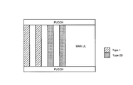
- FIG. 6 is a diagram for explaining the discovery resource pool.
- the Discovery resource pool is provided in a frequency band for uplink cellular communication (WAN UL).
- the Discovery resource pool includes a first Discovery resource pool used for the first discovery method and a second Discovery resource pool used for the second discovery method.
- the first Discovery resource pool and the second Discovery resource pool are alternately arranged in the time direction at a time interval shorter than the retransmission interval of uplink cellular communication (for example, 8 subframe intervals).
- a time interval shorter than the retransmission interval of uplink cellular communication for example, 8 subframe intervals.
- the first Discovery resource pool and the second Discovery resource pool do not overlap in the time direction, for example, the problem that the Discovery signal cannot be transmitted and received at the same time (so-called Half-duplex problem). Can be avoided.
- the width in the time direction of each of the first Discovery resource pool and the second Discovery resource pool is one subframe.
- each of the first Discovery resource pool and the second Discovery resource pool is arranged every three subframes.
- the first Discovery resource pool is arranged at a position where the subframe number is 0, 3, 6, 9, 12, or the like.
- the second Discovery resource pool is arranged at positions where the subframe numbers are 1, 4, 7, 10, 13, and the like.
- the first Discovery resource pool is arranged first and the second Discovery resource pool is arranged later, but the reverse may be possible.
- the arrangement of the first Discovery resource pool and the second Discovery resource pool may be different depending on the cell.
- the period in the time direction of the first Discovery resource pool may be different from the period in the time direction of the second Discovery resource pool at least for a certain period.
- the width in the time direction of the uplink cellular resource area where the radio resource candidates for uplink cellular communication are arranged is one subframe. Further, the uplink cellular resource region is arranged every three subframes. Specifically, the uplink cellular resource region is arranged at a position where the subframe number is 2, 5, 8, 11, 14, or the like. Therefore, the uplink cellular resource region and the Discovery resource pool (specifically, the first Discovery resource pool and the second Discovery resource pool) are alternately arranged in the time direction. Thereby, it can avoid that UE100 cannot perform either an upstream cellular communication or D2D discovery procedure for a long time.
- the LTE system has been described as an example of the mobile communication system.
- the embodiment is not limited to the LTE system, and the content of the present application may be applied to a system other than the LTE system.
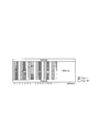
- Multiplexing of D2D discovery resource pool and WAN UL includes, for example, half-duplex constellation, in-band emission caused effects, UL throughput effects, and UL delay effects. There are some problems. As shown in FIG. 7, the first discovery method (Type 1 discovery), the second discovery method (Type 2 discovery), and the WAN UL are the TDM method due to the effects of half-duplex problem and in-band emission. Should be multiplexed.
- ⁇ Proposal 1 The first discovery method, the second discovery method, and WAN UL should be TDM.
- the WLAN UL resource should be inserted between the first and second discovery scheme regions as shown in FIG. D2D discovery resource restrictions should be specified and WAN UL allocation should be an eNB implementation.
- FIG. 6 is an example of the first discovery method, the second discovery method, and WAN UL multiplexing in consideration of time diversity gain.
- the discovery resource pool provided in the frequency band for uplink cellular communication can be appropriately arranged, which is useful in the mobile communication field. is there.
Landscapes
- Engineering & Computer Science (AREA)
- Computer Networks & Wireless Communication (AREA)
- Signal Processing (AREA)
- Databases & Information Systems (AREA)
- Mobile Radio Communication Systems (AREA)
Abstract
Description
実施形態に係る移動通信システムでは、近傍端末を発見するためのD2D発見手順用の発見リソースが配置される発見リソースプールが、上りリンクのセルラ通信用の周波数帯に設けられている。前記発見リソースプールは、ユーザ端末に固有に割り当てられない第1の発見リソースが配置される第1の発見リソースプールと、ユーザ端末毎に固有に割り当てられる第2の発見リソースが配置される第2の発見リソースプールと、を含む。前記第1の発見リソースプールと前記第2の発見リソースプールとは、前記上りセルラ通信の再送間隔よりも短い時間間隔で、時間方向において交互に配置される。
以下において、本出願の内容をLTEシステムに適用する場合の実施形態を説明する。
図1は、実施形態に係るLTEシステムの構成図である。図1に示すように、実施形態に係るLTEシステムは、UE(User Equipment)100、E-UTRAN(Evolved-UMTS Terrestrial Radio Access Network)10、及びEPC(Evolved Packet Core)20を備える。
以下において、D2D近傍サービスについて説明する。実施形態に係るLTEシステムは、D2D近傍サービスをサポートする。D2D近傍サービスについては非特許文献1に記載されているが、ここではその概要を説明する。
次に、D2D発見手順において用いられる無線リソースの候補が配置される発見リソースプール(Discoveryリソースプール)について、図6を用いて説明する。図6は、発見リソースプールを説明するための図である。
上述した実施形態では、移動通信システムの一例としてLTEシステムを説明したが、LTEシステムに限定されるものではなく、LTEシステム以外のシステムに本出願の内容を適用してもよい。
(1)導入
D2D発見及びWLANの共存について検討される。この付記において、D2D発見及びWLANの多重化について検討する。
この章では、D2D発見リソースプールの割り当てについて検討する。D2D発見リソースプールおよびWAN ULの多重化は、例えば、ハーフデュプレックス問題(half-duplex constraint)、インバンドエミッション(in-band emission)が原因の影響、ULのスループット影響、及び、UL遅延影響などのいくつかの問題がある。図7に示すように、第1の発見方式(Type 1 discovery)、第2の発見方式(Type 2 discovery)及びWAN ULは、ハーフデュプレックス問題及びインバンドエミッションが原因の影響のために、TDM方法で多重化すべきである。
Claims (4)
- 近傍端末を発見するためのD2D発見手順用の発見リソースが配置される発見リソースプールが、上りリンクのセルラ通信用の周波数帯に設けられており、
前記発見リソースプールは、ユーザ端末に固有に割り当てられない第1の発見リソースが配置される第1の発見リソースプールと、ユーザ端末毎に固有に割り当てられる第2の発見リソースが配置される第2の発見リソースプールと、を含み、
前記第1の発見リソースプールと前記第2の発見リソースプールとは、前記上りセルラ通信の再送間隔よりも短い時間間隔で、時間方向において交互に配置されることを特徴とする移動通信システム。 - 前記発見リソースプールと、上りリンクのセルラ通信用の無線リソース領域とが、時間方向において交互に配置されることを特徴とする請求項1に記載の移動通信システム。
- 近傍端末を発見するためのD2D発見手順用の発見リソースを用いて、D2D発見手順を行う制御部を備え、
前記発見リソースが配置される発見リソースプールが、上りリンクのセルラ通信用の周波数帯に設けられており、
前記発見リソースプールは、ユーザ端末に固有に割り当てられない第1の発見リソースが配置される第1の発見リソースプールと、ユーザ端末毎に固有に割り当てられる第2の発見リソースが配置される第2の発見リソースプールと、を含み、
前記第1の発見リソースプールと前記第2の発見リソースプールとは、前記上りセルラ通信の再送間隔よりも短い時間間隔で、時間方向において交互に配置されることを特徴とするユーザ端末。 - ユーザ端末に備えられるプロセッサであって、
近傍端末を発見するためのD2D発見手順用の発見リソースを用いて、D2D発見手順を行う処理を実行し、
前記発見リソースが配置される発見リソースプールが、上りリンクのセルラ通信用の周波数帯に設けられており、
前記発見リソースプールは、ユーザ端末に固有に割り当てられない第1の発見リソースが配置される第1の発見リソースプールと、ユーザ端末毎に固有に割り当てられる第2の発見リソースが配置される第2の発見リソースプールと、を含み、
前記第1の発見リソースプールと前記第2の発見リソースプールとは、前記上りセルラ通信の再送間隔よりも短い時間間隔で、時間方向において交互に配置されることを特徴とするプロセッサ。
Priority Applications (3)
| Application Number | Priority Date | Filing Date | Title |
|---|---|---|---|
| US15/308,965 US20170064535A1 (en) | 2014-05-09 | 2015-05-08 | Mobile communication system, user terminal, and processor |
| EP15789413.0A EP3142396A4 (en) | 2014-05-09 | 2015-05-08 | Mobile communication system, user terminal and processor |
| JP2016518238A JP6619730B2 (ja) | 2014-05-09 | 2015-05-08 | 移動通信システム、ユーザ端末及びプロセッサ |
Applications Claiming Priority (2)
| Application Number | Priority Date | Filing Date | Title |
|---|---|---|---|
| US201461991030P | 2014-05-09 | 2014-05-09 | |
| US61/991,030 | 2014-05-09 |
Publications (1)
| Publication Number | Publication Date |
|---|---|
| WO2015170767A1 true WO2015170767A1 (ja) | 2015-11-12 |
Family
ID=54392615
Family Applications (1)
| Application Number | Title | Priority Date | Filing Date |
|---|---|---|---|
| PCT/JP2015/063377 Ceased WO2015170767A1 (ja) | 2014-05-09 | 2015-05-08 | 移動通信システム、ユーザ端末及びプロセッサ |
Country Status (4)
| Country | Link |
|---|---|
| US (1) | US20170064535A1 (ja) |
| EP (1) | EP3142396A4 (ja) |
| JP (1) | JP6619730B2 (ja) |
| WO (1) | WO2015170767A1 (ja) |
Family Cites Families (5)
| Publication number | Priority date | Publication date | Assignee | Title |
|---|---|---|---|---|
| WO2010054288A2 (en) * | 2008-11-07 | 2010-05-14 | National Jewish Health | Diagnosis and treatment of autoimmune diseases by targeting autoimmune-related b cells ("abcs") |
| EP2756623B1 (en) * | 2011-09-12 | 2018-04-04 | Ntt Docomo, Inc. | Enhanced local access in mobile communications with fdd resource allocation |
| JP5980264B2 (ja) * | 2013-10-31 | 2016-08-31 | 株式会社Nttドコモ | ユーザ端末、無線基地局および無線通信方法 |
| JP6411725B2 (ja) * | 2013-10-31 | 2018-10-24 | 株式会社Nttドコモ | 無線基地局、ユーザ端末および無線通信方法 |
| KR102282371B1 (ko) * | 2013-12-13 | 2021-07-27 | 삼성전자주식회사 | 디바이스 대 디바이스 방식을 지원하는 통신 시스템에서 하이브리드 자동 반복 요구 송신과 디바이스 대 디바이스 송신간의 충돌을 방지하는 장치 및 방법 |
-
2015
- 2015-05-08 EP EP15789413.0A patent/EP3142396A4/en not_active Withdrawn
- 2015-05-08 US US15/308,965 patent/US20170064535A1/en not_active Abandoned
- 2015-05-08 WO PCT/JP2015/063377 patent/WO2015170767A1/ja not_active Ceased
- 2015-05-08 JP JP2016518238A patent/JP6619730B2/ja active Active
Non-Patent Citations (5)
| Title |
|---|
| ERICSSON: "Discovery Resource Allocation", 3GPP TSG-RAN WG1#76B RL-141388, XP050787058, Retrieved from the Internet <URL:http://www.3gpp.org/ftp/tsg_ran/WG1_RL1/TSGR1-76b/Docs/Rl-141388.zip> * |
| ERICSSON: "On Scrambling of D2D Physical Channels", 3GPP TSG-RAN WG1#76B R1- 141382, XP050787053, Retrieved from the Internet <URL:http://www.3gpp.org/ftp/tsg_ran/WG1_RL1/TSGR1_76b/Docs/R1-141382.zip> * |
| QUALCOMM INCORPORATED: "Coexistence of D2D discovery and WAN", 3GPP TSG-RAN WG2#85BIS R2-141677, XP050792811, Retrieved from the Internet <URL:http://www.3gpp.org/ftp/tsg_ran/WG2_RL2/TSGR2_85bis/Docs/R2-141677.zip> * |
| SAMSUNG: "Discovery Resources & UE-eNB Transmissions in Uplink", 3GPP TSG-RAN WG2#85BIS R2-141391, XP050792583, Retrieved from the Internet <URL:http://www.3gpp.org/ftp/tsg_ran/WG2_RL2/TSGR2_85bis/Docs/R2-141391.zip> * |
| See also references of EP3142396A4 * |
Also Published As
| Publication number | Publication date |
|---|---|
| EP3142396A4 (en) | 2018-01-10 |
| JP6619730B2 (ja) | 2019-12-11 |
| EP3142396A1 (en) | 2017-03-15 |
| JPWO2015170767A1 (ja) | 2017-04-20 |
| US20170064535A1 (en) | 2017-03-02 |
Similar Documents
| Publication | Publication Date | Title |
|---|---|---|
| JP5969722B1 (ja) | ユーザ端末、プロセッサ及び通信制御方法 | |
| JP6026549B2 (ja) | 移動通信システム、基地局及びユーザ端末 | |
| JP6499166B2 (ja) | 通信制御方法、ユーザ端末及び基地局 | |
| WO2015170730A1 (ja) | ユーザ端末及び基地局 | |
| JPWO2016021644A1 (ja) | 受信端末及び送信端末 | |
| JP6174141B2 (ja) | 通信制御方法及び基地局 | |
| WO2016021700A1 (ja) | 通信制御方法及びユーザ端末 | |
| JPWO2015141847A1 (ja) | 通信制御方法及び基地局 | |
| WO2015141727A1 (ja) | 通信制御方法及びユーザ端末 | |
| WO2015170765A1 (ja) | ユーザ端末及びプロセッサ | |
| JP6200078B2 (ja) | ユーザ端末、プロセッサ及び方法 | |
| JP6082671B2 (ja) | 通信制御装置及びユーザ端末 | |
| JPWO2016163431A1 (ja) | ユーザ端末及び制御方法 | |
| JP6130592B2 (ja) | ユーザ端末及び装置 | |
| JP6515083B2 (ja) | ユーザ端末及び通信制御方法 | |
| JP6619730B2 (ja) | 移動通信システム、ユーザ端末及びプロセッサ | |
| WO2014157397A1 (ja) | 通信制御方法、ユーザ端末、及び基地局 | |
| JP2018139430A (ja) | 移動通信システム、ユーザ端末、基地局、及びプロセッサ | |
| US10348461B2 (en) | Communication apparatus and communication method | |
| WO2016163474A1 (ja) | ユーザ端末 | |
| WO2016021701A1 (ja) | 基地局及びユーザ端末 | |
| JP2015159490A (ja) | 通信制御方法及び基地局 |
Legal Events
| Date | Code | Title | Description |
|---|---|---|---|
| 121 | Ep: the epo has been informed by wipo that ep was designated in this application |
Ref document number: 15789413 Country of ref document: EP Kind code of ref document: A1 |
|
| ENP | Entry into the national phase |
Ref document number: 2016518238 Country of ref document: JP Kind code of ref document: A |
|
| WWE | Wipo information: entry into national phase |
Ref document number: 15308965 Country of ref document: US |
|
| REEP | Request for entry into the european phase |
Ref document number: 2015789413 Country of ref document: EP |
|
| WWE | Wipo information: entry into national phase |
Ref document number: 2015789413 Country of ref document: EP |
|
| NENP | Non-entry into the national phase |
Ref country code: DE |