WO2015173848A1 - 蒸気圧縮式冷凍サイクル - Google Patents
蒸気圧縮式冷凍サイクル Download PDFInfo
- Publication number
- WO2015173848A1 WO2015173848A1 PCT/JP2014/002558 JP2014002558W WO2015173848A1 WO 2015173848 A1 WO2015173848 A1 WO 2015173848A1 JP 2014002558 W JP2014002558 W JP 2014002558W WO 2015173848 A1 WO2015173848 A1 WO 2015173848A1
- Authority
- WO
- WIPO (PCT)
- Prior art keywords
- refrigerant
- refrigeration cycle
- compression refrigeration
- vapor compression
- expansion device
- Prior art date
- Legal status (The legal status is an assumption and is not a legal conclusion. Google has not performed a legal analysis and makes no representation as to the accuracy of the status listed.)
- Ceased
Links
Images


Classifications
-
- F—MECHANICAL ENGINEERING; LIGHTING; HEATING; WEAPONS; BLASTING
- F25—REFRIGERATION OR COOLING; COMBINED HEATING AND REFRIGERATION SYSTEMS; HEAT PUMP SYSTEMS; MANUFACTURE OR STORAGE OF ICE; LIQUEFACTION SOLIDIFICATION OF GASES
- F25B—REFRIGERATION MACHINES, PLANTS OR SYSTEMS; COMBINED HEATING AND REFRIGERATION SYSTEMS; HEAT PUMP SYSTEMS
- F25B13/00—Compression machines, plants or systems, with reversible cycle
-
- F—MECHANICAL ENGINEERING; LIGHTING; HEATING; WEAPONS; BLASTING
- F25—REFRIGERATION OR COOLING; COMBINED HEATING AND REFRIGERATION SYSTEMS; HEAT PUMP SYSTEMS; MANUFACTURE OR STORAGE OF ICE; LIQUEFACTION SOLIDIFICATION OF GASES
- F25B—REFRIGERATION MACHINES, PLANTS OR SYSTEMS; COMBINED HEATING AND REFRIGERATION SYSTEMS; HEAT PUMP SYSTEMS
- F25B1/00—Compression machines, plants or systems with non-reversible cycle
-
- F—MECHANICAL ENGINEERING; LIGHTING; HEATING; WEAPONS; BLASTING
- F25—REFRIGERATION OR COOLING; COMBINED HEATING AND REFRIGERATION SYSTEMS; HEAT PUMP SYSTEMS; MANUFACTURE OR STORAGE OF ICE; LIQUEFACTION SOLIDIFICATION OF GASES
- F25B—REFRIGERATION MACHINES, PLANTS OR SYSTEMS; COMBINED HEATING AND REFRIGERATION SYSTEMS; HEAT PUMP SYSTEMS
- F25B2313/00—Compression machines, plants or systems with reversible cycle not otherwise provided for
- F25B2313/027—Compression machines, plants or systems with reversible cycle not otherwise provided for characterised by the reversing means
- F25B2313/02741—Compression machines, plants or systems with reversible cycle not otherwise provided for characterised by the reversing means using one four-way valve
-
- F—MECHANICAL ENGINEERING; LIGHTING; HEATING; WEAPONS; BLASTING
- F25—REFRIGERATION OR COOLING; COMBINED HEATING AND REFRIGERATION SYSTEMS; HEAT PUMP SYSTEMS; MANUFACTURE OR STORAGE OF ICE; LIQUEFACTION SOLIDIFICATION OF GASES
- F25B—REFRIGERATION MACHINES, PLANTS OR SYSTEMS; COMBINED HEATING AND REFRIGERATION SYSTEMS; HEAT PUMP SYSTEMS
- F25B2400/00—General features or devices for refrigeration machines, plants or systems, combined heating and refrigeration systems or heat-pump systems, i.e. not limited to a particular subgroup of F25B
- F25B2400/13—Economisers
-
- F—MECHANICAL ENGINEERING; LIGHTING; HEATING; WEAPONS; BLASTING
- F25—REFRIGERATION OR COOLING; COMBINED HEATING AND REFRIGERATION SYSTEMS; HEAT PUMP SYSTEMS; MANUFACTURE OR STORAGE OF ICE; LIQUEFACTION SOLIDIFICATION OF GASES
- F25B—REFRIGERATION MACHINES, PLANTS OR SYSTEMS; COMBINED HEATING AND REFRIGERATION SYSTEMS; HEAT PUMP SYSTEMS
- F25B2400/00—General features or devices for refrigeration machines, plants or systems, combined heating and refrigeration systems or heat-pump systems, i.e. not limited to a particular subgroup of F25B
- F25B2400/16—Receivers
-
- F—MECHANICAL ENGINEERING; LIGHTING; HEATING; WEAPONS; BLASTING
- F25—REFRIGERATION OR COOLING; COMBINED HEATING AND REFRIGERATION SYSTEMS; HEAT PUMP SYSTEMS; MANUFACTURE OR STORAGE OF ICE; LIQUEFACTION SOLIDIFICATION OF GASES
- F25B—REFRIGERATION MACHINES, PLANTS OR SYSTEMS; COMBINED HEATING AND REFRIGERATION SYSTEMS; HEAT PUMP SYSTEMS
- F25B2600/00—Control issues
- F25B2600/25—Control of valves
- F25B2600/2509—Economiser valves
-
- F—MECHANICAL ENGINEERING; LIGHTING; HEATING; WEAPONS; BLASTING
- F25—REFRIGERATION OR COOLING; COMBINED HEATING AND REFRIGERATION SYSTEMS; HEAT PUMP SYSTEMS; MANUFACTURE OR STORAGE OF ICE; LIQUEFACTION SOLIDIFICATION OF GASES
- F25B—REFRIGERATION MACHINES, PLANTS OR SYSTEMS; COMBINED HEATING AND REFRIGERATION SYSTEMS; HEAT PUMP SYSTEMS
- F25B2700/00—Sensing or detecting of parameters; Sensors therefor
- F25B2700/19—Pressures
- F25B2700/193—Pressures of the compressor
- F25B2700/1933—Suction pressures
-
- F—MECHANICAL ENGINEERING; LIGHTING; HEATING; WEAPONS; BLASTING
- F25—REFRIGERATION OR COOLING; COMBINED HEATING AND REFRIGERATION SYSTEMS; HEAT PUMP SYSTEMS; MANUFACTURE OR STORAGE OF ICE; LIQUEFACTION SOLIDIFICATION OF GASES
- F25B—REFRIGERATION MACHINES, PLANTS OR SYSTEMS; COMBINED HEATING AND REFRIGERATION SYSTEMS; HEAT PUMP SYSTEMS
- F25B2700/00—Sensing or detecting of parameters; Sensors therefor
- F25B2700/21—Temperatures
- F25B2700/2115—Temperatures of a compressor or the drive means therefor
- F25B2700/21151—Temperatures of a compressor or the drive means therefor at the suction side of the compressor
Definitions
- the present invention relates to a refrigeration cycle of an intermediate injection system using HFO refrigerants such as HFO-1234yF and HFO-1234ze, which are low GWP refrigerants, and particularly to improvement of the operation efficiency thereof.
- HFO refrigerants such as HFO-1234yF and HFO-1234ze, which are low GWP refrigerants, and particularly to improvement of the operation efficiency thereof.
- the refrigerant efficiency is improved by the intermediate injection method as one of the techniques, but the coefficient of performance COP (Coefficent of Performance) by the intermediate injection circuit in the main refrigeration cycle thereby.
- This improvement is realized by improving the efficiency of the compressor and improving the cycle efficiency.
- the refrigerant temperature is raised.
- the refrigerant circulation amount on the gas cooler side is increased and the heating capacity and the COP are improved.
- an intermediate injection port inlet may be provided in advance on the side surface of the compressor, and a refrigerant in a heated gas state may be injected from this portion.
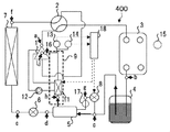
- Patent Document 1 As for the outline of the conventional vapor compression refrigeration cycle, a compressor having an injection port serving as a refrigerant passage in the middle part of the compression stroke for compressing and discharging the sucked refrigerant, a four-way valve, a heat source side expansion device, a heat source side It comprises a heat exchanger, a load side expansion device, and a load side heat exchanger, which are connected in an annular shape so that the refrigerant circulates. (See Patent Document 1)
- Patent Document 1 The configuration of the vapor compression refrigeration cycle disclosed in Patent Document 1 will be described below with reference to FIG. This configuration is basically the same except for the above-mentioned Patent Document 1 and specific components (liquid receiver 4), and FIG. 1 will be used as appropriate in the description of the configuration of the prior art.
- This vapor compression refrigeration cycle is a vapor compression refrigeration cycle 100 having an intermediate injection port 16 for injecting HFO as a new refrigerant into the compressor 1, and the compressor 1 and the heat on the high temperature side.
- a refrigeration cycle constructed by connecting a condenser 3 as an exchanger, an expansion valve 8 as a second expansion device, and an evaporator 7 as a low-temperature heat exchanger with refrigerant piping, and this refrigeration cycle
- the compressor 1, the condenser 3, the expansion valve 8, and the evaporator 7 are connected to each other by a refrigerant pipe for circulating the refrigerant. .
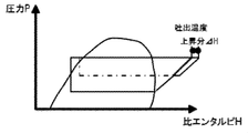
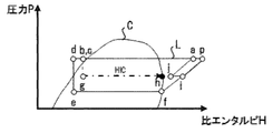
- FIG. 11 shows a saturation curve (C) composed of a saturated liquid line and a saturated vapor line. , And a PH line (L).
- the outline is a substantially unequal leg trapezoidal part (the former) whose upper side is longer than the lower side, and its unequal leg trapezoid.
- the two figures are combined with the parallelogram part (the latter) in contact with the upwardly rising part so as to be included in the part.
- the straight line pd is composed of the upper side
- the straight line de is composed of the short leg side
- the straight line ef is composed of the lower side (lower side ⁇ upper side)
- the straight line fp is composed of the long leg side.
- the straight line ap is composed of the upper side
- the straight line pi is composed of the right side
- the straight line ij is composed of the lower side
- the straight line ja is composed of the left side. Since b and c overlap and are the same point, b and c are displayed.
- the portion indicated by the alternate long and short dash line on the inside of the substantially unequal leg trapezoid corresponds to the intermediate injection.
- the portion of the alternate long and short dash line is composed of a straight line b-g parallel to the straight line de and a straight line gh parallel to the straight line ef. Further, i and j are located on an extension line of the straight line gh.
- each of a to j located in FIG. 11 corresponds to each of a to j of the refrigeration cycle in FIG.
- each of a to j indicates a position on the configuration of the refrigeration cycle.
- a to j indicate the state of the refrigerant corresponding to these positions.
- a indicates the state of the refrigerant corresponding to the outlet of the compressor 1, and the pressure is Pa and the specific enthalpy is Ha.
- the state a shifts to a state b located in the left direction parallel to the horizontal axis along the solid line.
- c shows the state of the refrigerant flowing through the inlet of the second expansion device 8, and c is plotted at the same position as b.
- the state c shifts to the state d located in the left direction parallel to the horizontal axis along the solid line.
- the main refrigerant pipe connected to the evaporator 7 and the sub refrigerant pipe (described later) connected to the injection port 16 exchange heat with each other. That is, the main refrigerant pipe releases heat and the sub refrigerant pipe absorbs heat.
- the refrigerant flowing through the main refrigerant pipe corresponds to reducing its enthalpy.
- the state d shifts to the state e located in the downward direction parallel to the vertical axis along the solid line. This corresponds to the fact that the refrigerant expands when the refrigerant passes through the first expansion device 6, thereby reducing the pressure.
- the state e shifts to a state f located in the right direction parallel to the horizontal axis along the solid line.
- the state f shifts to the state i located in the upper right direction along the straight solid line rising upward. This corresponds to an increase in pressure and enthalpy of the refrigerant by the compressor 1 condensing the refrigerant to an intermediate pressure inside the compressor 1.
- the pressure Pf increases to Pi, and the specific enthalpy Hf increases to Hi.
- the state b (c) shifts to a state g positioned in the downward direction parallel to the vertical axis along the one-dot chain line. This corresponds to the fact that when the refrigerant passes through the second expansion device 8, the pressure expands due to the refrigerant expanding.
- the state g shifts to the state h located in the right direction parallel to the horizontal axis along the one-dot chain line. This corresponds to the fact that when the refrigerant passes through the internal heat exchanger 5, the refrigerant absorbs heat by heat exchange, and this refrigerant increases its enthalpy.
- h is on the saturation curve (C) line or inside the C line.
- the state j shifts to the state a located in the upper right direction along the straight solid line rising to the right.
- the compressor 1 compresses the refrigerant from medium pressure to high pressure, the refrigerant increases pressure and enthalpy.
- the pressure Pj increases to Pa, and the specific enthalpy Hj increases to Ha.
- the pressure is Pa and the specific enthalpy is Ha
- the refrigerant returns to the original refrigerant state a flowing through the outlet of the compressor 1, and one cycle is completed.
- the first compression step in the period from f to i and the second in the period from j to a are shown.
- the suction SH is not sufficiently given to the refrigerant injected from the injection port 16. That is, in FIG. 11, h is on the curve of the saturated vapor line, j is slightly on the right side of the saturated vapor line, and is on the left side of the compression process in the PH diagram for the vapor compression refrigeration cycle. For this reason, the portion corresponding to the compression process in the PH diagram does not exist at an appropriate position on the PH diagram. That is, this is because the control device 18 does not sufficiently give the intake SH to the refrigerant inside the compressor 1 and the expansion valve 8 cannot be controlled so that j is located on the right side of the saturated vapor line.
- the present invention was made to solve the above-mentioned problems, and even when using an HFO refrigerant that tends to lower the discharge temperature on the compressor outlet side, the refrigerant discharge temperature is prevented from lowering, A highly efficient hot water supply / heating refrigeration cycle is obtained.
- the vapor compression refrigeration cycle of the present invention is A vapor compression refrigeration cycle using HFO as a refrigerant
- the vapor compression refrigeration cycle is A compressor provided with an injection port for injecting refrigerant circulating in the vapor compression refrigeration cycle; A pressure sensor and a temperature sensor for measuring the pressure and temperature close to the injection port; An expansion device that opens and closes the refrigerant so as to compress and expand; A control device for controlling the opening degree of the expansion device based on the pressure and temperature obtained by the pressure sensor and the temperature sensor, In the control device, the portion corresponding to the compression step in the PH diagram relating to the vapor compression refrigeration cycle is located outside the saturation curve composed of the saturated liquid line and the saturated vapor line, and from the critical pressure. Is a vapor compression refrigeration cycle in which the expansion device is controlled so as to be located on the lower side and on the higher enthalpy region side than the saturated vapor line.
- the vapor compression refrigeration cycle according to the invention keeps the temperature of the refrigerant injected into the intermediate injection compressor in an appropriate overheated state inside the compressor, and even when using the HFO refrigerant, It is possible to prevent the discharge temperature from being lowered at the outlet of the compressor caused by the injection, and to improve the operating efficiency (COP) of the refrigeration cycle.
- COP operating efficiency
- FIG. 1 is a circuit diagram of a vapor compression refrigeration cycle 100 showing Embodiment 1 of the present invention.
- FIG. 3 is a PH diagram illustrating a state of a refrigerant according to the first embodiment.
- FIG. 6 is a PH diagram showing an image of an increase in discharge temperature when heating refrigerant is supplied to the intermediate injection port 16. It is an opening degree control flowchart of the 2nd expansion device 8 concerning Embodiment 1.
- FIG. It is a circuit diagram of the vapor
- FIG. FIG. 10 is a block diagram showing an outline of a signal flow according to the second embodiment.
- FIG. 10 is a block diagram showing an outline of a signal flow according to the second embodiment.
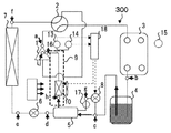
- FIG. 10 is a circuit diagram of a vapor compression refrigeration cycle 300 when exhaust heat from a control panel is used according to a modification of the second embodiment.
- 6 is a circuit diagram of a vapor compression refrigeration cycle 400 when exhaust heat of the compressor 1 is used according to Embodiment 3.
- FIG. FIG. 10 is a block diagram illustrating an outline of a signal flow according to a third embodiment.
- FIG. 6 is a circuit diagram of a vapor compression refrigeration cycle 500 when using gas refrigerant injection in a liquid receiver 4 according to a fourth embodiment. It is a PH diagram which shows the state of the refrigerant
- FIG. The relationship between inhalation SH and the coefficient of performance COP in the intermediate injection port 16 is shown.
- FIG. FIG. 1 shows an entire vapor compression refrigeration cycle 100 according to Embodiment 1 of the present invention.
- a hot water supply refrigeration cycle installed as a home water heater or a building water heater will be described.
- the vapor compression refrigeration cycle 100 includes a compressor 1 that compresses a refrigerant, a four-way valve 2 that changes the flow direction of the refrigerant, a condenser 3, a liquid receiver 4 that is a high-pressure container that stores high-pressure liquid refrigerant, An internal heat exchanger 5 to be exchanged, an evaporator 7, a first expansion device 6 and a second expansion device 8 for expanding the refrigerant, and an injection circuit 9 for heating the refrigerant injected from the injection port 16 Has been.
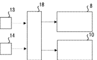
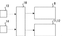
- a pressure sensor 13 and a temperature sensor 14 for measuring the pressure and temperature of the refrigerant are provided in the vicinity of the inlet of the injection port 16, and a control device 18 for controlling the opening degree of the second expansion device 8 is further provided. Is provided.
- the control device 18 has a function of controlling the opening degree of the second expansion device 8 based on the refrigerant information obtained by the pressure sensor 13 and the temperature sensor 14.
- the liquid receiver 4 is installed in the middle path of the pipe connecting the output side of the condenser 3 and the input side of the second expansion device 8, and the gas-liquid two-phase flow stored in the liquid receiver 4
- the refrigerant in the state is branched from the middle of the main refrigerant pipe described later.
- the refrigerant in the gas-liquid two-phase flow state stored in the liquid receiver 4 one is the upper inlet of the internal heat exchanger 5 through the second expansion device 8, and the other is the internal heat exchanger 5. Flows into the lower entrance.
- the internal heat exchanger 5 includes, inside, a main refrigerant pipe connecting the liquid receiver 4 and the expansion device 6, and a sub refrigerant pipe connecting the liquid receiver 4 and the expansion device 6 via the second expansion device 8. These two refrigerant pipes are arranged close to each other, and heat exchange is performed between the refrigerant flowing through the main refrigerant pipe and the refrigerant flowing through the sub refrigerant pipe. As a result, heat is released from the main refrigerant pipe to the sub refrigerant pipe, heat is absorbed from the sub refrigerant pipe to the main refrigerant pipe, the temperature of the refrigerant flowing through the main refrigerant pipe decreases, and the refrigerant flowing through the sub refrigerant pipe Temperature rises.
- the first expansion device 6 and the second expansion device 8 use expansion valves so as to compress and expand the refrigerant in the main refrigerant pipe and the sub refrigerant pipe, respectively.
- the injection circuit 9 heats the refrigerant that is injected into the compressor 1 from the injection port 16 including the sub refrigerant pipe.
- the injection port 16 is formed on the side surface of the compressor 1 in order to inject the refrigerant in a heated gas state into the compressor 1. Further, the pressure sensor 13 and the temperature sensor 14 are installed in the vicinity of the injection port 16 and measure the pressure and temperature of the refrigerant. A temperature sensor 17 is also installed at the inlet of the internal heat exchanger 5. Furthermore, the outside air temperature sensor 15 is disposed in the vicinity of the condenser 3 and measures the air temperature in the vicinity of the condenser 3.
- the control device 18 is connected to the second expansion device 8 via a communication line or the like, and based on the refrigerant information obtained by the pressure sensor 13 and the temperature sensor 14, the second expansion device. 8 is controlled.
- the control device 18 is configured so that the refrigerant injected from the compressor injection port is heated steam having a superheat degree of 20 ° C. or higher and a high-low pressure ratio inside the compressor of 0.35 or higher.
- the opening degree of the second expansion device 8 is controlled.
- the condenser 3 corresponds to a heat exchanger on the high temperature side, and the high heat obtained by the condenser 3 is used as a heat source for high temperature on the secondary side.
- the evaporator 7 corresponds to a low-temperature heat exchanger, and the low heat obtained by the evaporator 7 is used as a low-temperature heat source on the secondary side.
- the approximate shape of the PH line (L) in FIG. 2 is in contact with a substantially uneven trapezoidal trapezoidal part (the former) whose upper side is longer than the lower side, and an upwardly shouldered part of the unequal legged trapezoidal part.
- the point that two figures with the parallelogram portion (the latter) are synthesized is the same, but the latter is different in that it is outside the former.
- each of a to j (refrigerant state) located in FIG. 2 corresponds to each of the refrigeration cycle a to j (position on the configuration of the refrigeration cycle) in FIG.
- the points are the same, the operation of the vapor compression refrigeration cycle of the present invention is different in that it corresponds to FIG.
- the operation period of the vapor compression refrigeration cycle of the present invention is divided into a first period (a period from a to g), a second period (a period from g to h), and a third period (h to a It is divided into three periods).
- first period and the third period are the same as in the prior art.
- second period the period from g to h
- the second period different from the prior art will be described mainly.
- the state g shifts to a state h located in the right direction parallel to the horizontal axis along the alternate long and short dash line.
- This corresponds to the fact that when the refrigerant passes through the internal heat exchanger 5, the refrigerant absorbs heat by heat exchange, and this refrigerant increases its enthalpy.
- h is outside the saturation curve (C) line.
- the state g moves further along the alternate long and short dash line in the right direction parallel to the horizontal axis as described in FIG. This indicates that when the refrigerant passes through the internal heat exchanger 5, the refrigerant absorbs more heat than described in FIG. 11 by heat exchange, and the refrigerant that has absorbed this heat
- the enthalpy of the refrigerant supplied from the injection port 16 and inside the compressor 1 is further increased.
- the states h and j are shifted to the high enthalpy region side (right side) as compared with the conventional PH diagram previously described with reference to FIG. That is, it can be seen that the specific enthalpy of the refrigerant is increased in the compressor 1 in the first embodiment of the present invention.
- Condition 1 It is located outside a saturation curve (C) composed of a saturated liquid line and a saturated vapor line.
- Condition 2 Located below the critical pressure. (In other words, the states h and j on the PH line (L) are below the states a and p)
- Condition 3 It is located on the high enthalpy region side sufficiently from the saturated vapor line.
- the states h and j on the PH line (L) are on the right side of the state i) That is, this is because the control device 18 controls the opening / closing operation of the expansion valve 8 so that the refrigerant SH is sufficiently provided with the suction SH inside the compressor 1 and the point j is located on the right side of the saturated vapor line. It is none other than being.
- the portion of the straight line ap that extends from the point a to the point p indicates the increase ⁇ H in the refrigerant discharge temperature. (See FIG. 3).
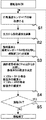
- step S1 to step S5 the processing procedure shown in FIG. This will be described with reference to FIG.
- Step S1 When the operation command for the vapor compression refrigeration cycle 100 is turned ON, the outside air temperature sensor 15 detects the air temperature in the vicinity of the condenser 3. (Step S1).
- the control device 18 detects the pressure value of the refrigerant from the pressure sensor 13 and acquires the temperature of the refrigerant from the temperature sensor 15. Thereafter, the control device 18 calculates the saturation temperature of the refrigerant at the pressure based on the pressure value obtained from the pressure sensor 13. (Step S2).
- the control device 18 compares the saturation temperature with the temperature obtained by the temperature sensor 17 installed at the inlet of the internal heat exchanger 5 to overheat the refrigerant.
- the degree SH is calculated. (Step S3).
- the superheat degree SH is a temperature difference between the temperature on the inlet side of the internal heat exchanger 5 and the temperature on the outlet side.
- the superheat degree SH is compared with a superheat degree target value SHs which is a preset target value, and the control device 18 determines the opening degree of the second expansion device 8 based on the comparison result.
- Step S4 the opening degree of the second expansion device 8 is controlled to be increased.
- step S ⁇ b> 4 the control device 18 instructs the second expansion device 8 to determine the opening degree of the second expansion device 8 and the determination result.
- step S4 the control device 18 further determines whether or not control is necessary after performing the opening degree control of the second expansion device 8. That is, it is determined whether or not the continuous operation of the vapor compression refrigeration cycle 100 is necessary. If further continuous operation is necessary, the process proceeds to YES and returns to S1. If the continuous operation is not necessary, the process proceeds to NO and control is performed. The opening control of the second expansion device 8 by the device 18 is finished. (Step S5).
- step S5 is a step of determining whether or not the opening degree of the second expansion device 8 is calculated again.
- FIG. 1 In the vapor compression refrigeration cycle 200 showing the second embodiment of the present invention, the system configuration, the PH diagram, and the control flow are basically the same as those in the first embodiment, and are therefore omitted. 5 will be mainly described with reference to FIG.
- a blower heat exchanger 10 as a second heating means is newly installed in the vicinity of the auxiliary refrigerant pipe introduced into the injection port 16, and the internal heat exchanger 5 and the blower heat are installed.
- the refrigerant injected into the compressor 1 from the injection port 16 is heated using two types of heating means with the exchanger 10.
- the second embodiment in addition to using two types of heating means, a fan is attached to the blower heat exchanger 10 as the second heating means, and the rotation speed is controlled by an inverter. For this reason, it is possible to obtain a sufficient amount of heat exchange while designing the heat exchanger in a compact manner, and it is possible to stably supply superheated refrigerant at a desired temperature from the injection port 16 of the compressor.
- the states h and j are shifted to the high enthalpy region side (right side) as compared with the PH diagram of the first embodiment.
- the fan installation can be omitted by increasing the heat exchanger area of the blower heat exchanger 10.
- the exhaust heat of the control panel may be used as a heat source in addition to the blower heat exchanger 10 (see FIG. 7). In this case, an effect of adding a further superheat degree SH is expected.
- the control device 18 uses the pressure sensor 13 and the temperature sensor 14 to detect the refrigerant value detected by the second expansion device 8 and the blower heat exchange. The flow of control signals when controlling the instrument 10 is shown.
- Embodiment 3 In the vapor compression refrigeration cycle 300 showing the third embodiment of the present invention, the system configuration, the PH diagram, and the control flow are basically the same as those in the first embodiment, and are therefore omitted. 8 will be mainly described with reference to FIG.
- a circulating heat exchanger 11 as a second heating means is provided at the same position as the blower heat exchanger 10 of the second embodiment, and is replaced.
- circulation heat exchange is a second heating means for exchanging heat with the liquid (air or brine) from which the exhaust heat of the compressor 1 is recovered.
- the heater 11 and the pump 12 are newly installed to heat the refrigerant injected into the compressor 1 from the injection port 16 using two types of heating means, that is, the internal heat exchanger 5 and the circulation heat exchanger 11. carry out.
- the circulation heat exchanger 11 heats the refrigerant flowing through the sub refrigerant pipe using the liquid (air or brine) recovered from the exhaust heat of the compressor 1 in the vicinity of the sub refrigerant pipe.
- the pump 12 is disposed in the middle of a pipe connecting the compressor 1 and the circulation heat exchanger 11, and circulates liquid (air or brine) recovered from the exhaust heat of the compressor 1.
- the states h and j are shifted to the high enthalpy region side (right side) as compared with the PH diagram of the first embodiment.
- the injection circuit 9 is directly wound around the compressor 1 to perform heat exchange, whereby the circulation heat exchanger 11 and the pump 12 and the accompanying heat (water or brine) are attached.
- the liquid circuit consisting of can also be omitted.
- the modification of the third embodiment is a liquid-type winding type, but the heat source is still a liquid-type heating type.
- the control device 18 uses the second expansion device 8 and the circulation heat exchange based on the detected values of the refrigerant detected by the pressure sensor 13 and the temperature sensor 14. The flow of control signals when controlling the vessel 11 and the pump 12 is shown.
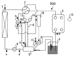
- Embodiment 4 FIG.
- the system configuration, the PH diagram, and the control flow are basically the same as those in the first embodiment, and are therefore omitted. 10 will be mainly described with reference to FIG.
- the gas portion (gas refrigerant) in the gas phase which has become the heating vapor among the refrigerant in the gas-liquid two-phase flow state stored in the receiver 4 is second from the upper portion of the receiver 4.
- This gas refrigerant output path is added so as to flow into the input side of the expansion device 8, thereby improving the heat exchange efficiency in the internal heat exchanger 5 as a single heating means.
- the difference from the first to third embodiments in the configuration is that an additional output path for the gas refrigerant is additionally provided in the upper part of the liquid receiver 4.
- One end of the refrigerant pipe is in contact with the liquid surface near the upper part of the receiver 4, and the other end is connected to the input side of the second expansion device 8.
- the gas portion in the gas phase that has become heated steam flows into the input side of the second expansion device 8
- the second The liquid part flows into the lower inlet of the internal heat exchanger 5 through the expansion device 8. Thereafter, heat is exchanged between the refrigerant flowing through the sub refrigerant pipe and the refrigerant flowing through the main refrigerant pipe inside the internal heat exchanger 5.
- the internal heat exchanger 5 it becomes easy to add the superheat degree SH to the HFO refrigerant flowing through the sub refrigerant pipe introduced into the injection port 16, and compared with the first embodiment, at the compressor outlet side.
- the discharge temperature can be prevented from decreasing, and a more efficient hot water supply / heating refrigeration cycle can be realized.
- the states h and j are shifted to the high enthalpy region side (right side) as compared with the PH diagrams of the first to third embodiments.
- the temperature of the refrigerant that is intermediately injected into the compressor is maintained in an appropriate overheated state, and the discharge temperature at the outlet of the compressor. Can be prevented, and as a result, the operating efficiency (COP) of the refrigeration cycle can be improved.
- vapor compression refrigeration cycle of the present invention may be applied not only to the hot water supply utilization field but also to other fields.
Landscapes
- Engineering & Computer Science (AREA)
- Physics & Mathematics (AREA)
- Mechanical Engineering (AREA)
- Thermal Sciences (AREA)
- General Engineering & Computer Science (AREA)
- Heat-Pump Type And Storage Water Heaters (AREA)
- Compression-Type Refrigeration Machines With Reversible Cycles (AREA)
Abstract
Description
しかし、このHFO冷媒は従来のHFC冷媒と比較して、圧縮機出口での冷媒が低密度、低潜熱量、低吐出温度になってしまうという難点がある。このため、この冷媒を給湯・加熱用途に用いる場合にCOPが低下する、すなわち、運転効率の低下が生じていた。
その従来の蒸気圧縮式冷凍サイクルの概要については、吸入した冷媒を圧縮して吐出する圧縮行程の中間部分に冷媒通過口となるインジェクションポートを有する圧縮機、四方弁、熱源側絞り装置、熱源側熱交換器、負荷側絞り装置及び負荷側熱交換器とから構成され、冷媒が循環するようにそれらを環状に接続されている。
(特許文献1参照)
以下、前者は、直線p―dは上辺、直線d―eは短脚辺、直線e―fは下辺(下辺<上辺)、直線f―pは長脚辺から構成されている。後者は、直線a―pは上辺、直線p―iは右辺、直線i―jは下辺、直線j―aは左辺から構成されている。なお、bとcとは、重なっており同じ点であるので、b,cと表示してある。
cは、第2の膨張装置8の入口を流れる冷媒の状態を示し、cは、bと同じ位置にプロットされている。ここで、図11のP―H線図において、bとcとが同じ位置にプロットされているのは、図1に示す構成で冷媒配管中を流れる冷媒の位置は異なるが、図11に示すP―H線図上での冷媒の状態(圧力、比エントロピー)は同じためである。
なお、以上の説明から明らかなように、上記P―H線(L)図中にはfからiに至るまでの期間の第1の圧縮工程と、jからaに至るまでの期間の第2の圧縮工程の二つの圧縮工程が存在し、それら二つの圧縮工程にともに共通して該当する部分は、単に圧縮工程という。
冷媒としてHFOを使用する蒸気圧縮式冷凍サイクルであって、
上記蒸気圧縮式冷凍サイクルは、
上記蒸気圧縮式冷凍サイクル内を循環する冷媒を注入するためのインジェクションポートが設けられた圧縮機と、
このインジェクションポートに近接された圧力及び温度を計測する圧力センサ及び温度センサと、
上記冷媒を圧縮膨張させるように開閉する動作を行う膨張装置と、
上記圧力センサ及び温度センサで得られた圧力及び温度に基づいて、前記膨張装置の開度を制御する制御装置と、を備え、
前記制御装置は、上記蒸気圧縮式冷凍サイクルに関するP―H線図のうち、圧縮工程に相当する部分が、飽和液線と飽和蒸気線とからなる飽和曲線の外側に位置するとともに、臨界圧力よりも下側に位置し、かつ、飽和蒸気線よりも高エンタルピー領域側に位置するように、前記膨張装置を制御することを特徴とする蒸気圧縮式冷凍サイクルである。
図1は、この発明の実施の形態1に係る、蒸気圧縮式冷凍サイクル100の全体を示している。以下、一例として、家庭用の給湯機や、ビル用の給湯機として設置される給湯用冷凍サイクルとして説明する。
蒸気圧縮式冷凍サイクル100は、冷媒を圧縮する圧縮機1と、冷媒の流れ方向を変更する四方弁2と、凝縮器3と、高圧液冷媒を溜める高圧容器である受液器4と、熱交換する内部熱交換器5と、蒸発器7と、冷媒を膨張する第1の膨張装置6及び第2の膨張装置8と、インジェクションポート16から注入する冷媒を加熱するインジェクション回路9と、から構成されている。
また、インジェクションポート16の入口近傍には、冷媒の圧力及び温度を計測する圧力センサ13及び温度センサ14が設けられており、更に上記第2の膨張装置8の開度を制御する制御装置18が設けられている。そして、この制御装置18は上記圧力センサ13及び、温度センサ14で得られた冷媒の情報をもとに、第2の膨張装置8の開度を制御する機能を有する。
本願発明の蒸気圧縮式冷凍サイクルの動作は後述されるが、その概要は図11に示された状態h,jが右側にシフトする点(高エンタルピー領域側にシフトしている)を除き、従来のP―H線図と同じであるので説明を省略し、従来との相違点を主体に図2で説明する。
また、図2中に位置しているaからjまでのそれぞれ(冷媒の状態)が、図1中の冷凍サイクルのaからjまでのそれぞれ(冷凍サイクルの構成上の位置)に対応している点は同じであるが、本願発明の蒸気圧縮式冷凍サイクルの動作は図2に対応している点が異なる。
すなわち、点gから点hに至るまでの期間中においては、状態gが一点鎖線に沿って横軸に平行な右方向に図11で説明したよりさらに大きく動いている。これは、冷媒が内部熱交換器5を通過する際に、冷媒が熱交換により図11で説明したよりも多くの熱を吸収していることを示しており、この熱を吸収した冷媒がこのインジェクションポート16から供給され、圧縮機1の内部の冷媒のエンタルピーがさらに増加している。
条件1:飽和液線と飽和蒸気線とからなる飽和曲線(C)の外側に位置する。
条件2:臨界圧力よりも下側に位置する。(換言すれば、P―H線(L)上の状態h,jが状態a,pよりも下側にある)
条件3:飽和蒸気線よりも充分に高エンタルピー領域側に位置する。(換言すれば、P―H線(L)上の状態h,jが状態iよりも右側にある)
すなわち、これは、制御装置18が、圧縮機1の内部で冷媒に吸入SHを充分に与えて、点jが飽和蒸気線よりも右側に位置するように膨張弁8の開閉動作を制御していることに他ならない。
ここで、ステップS4において、制御装置18が第2の膨張装置8の開度決定及びその決定結果を第2の膨張装置8に指示する。
ここで、ステップS5は、第2の膨張装置8の開度を再度計算させるか、させないかを判断するステップである。
この発明の実施の形態2を示す蒸気圧縮式冷凍サイクル200では、システム構成、P―H線図、及び、制御フローは基本的に実施の形態1と同じであるので省略し、実施の形態1との相違点を主体に図5で説明する。
なお、第6図に示されているように、制御装置18が、圧力センサ13及び、温度センサ14で検出された冷媒の検出値をもとに、第2の膨張装置8及び送風式熱交換器10を制御する際の制御信号の流れが示されている。
この発明の実施の形態3を示す蒸気圧縮式冷凍サイクル300では、システム構成、P―H線図、及び、制御フローは基本的に実施の形態1と同じであるので省略し、実施の形態2との相違点を主体に図8で説明する。
なお、第9図に示されているように、制御装置18が、圧力センサ13及び、温度センサ14で検出された冷媒の検出値をもとに、第2の膨張装置8及び循環式熱交換器11、ポンプ12を制御する際の制御信号の流れが示されている。
この発明の実施の形態4を示す蒸気圧縮式冷凍サイクル500では、システム構成、P―H線図、及び、制御フローは基本的に実施の形態1と同じであるので省略し、実施の形態1との相違点を主体に図10で説明する。
Claims (5)
- 冷媒としてHFOを使用する蒸気圧縮式冷凍サイクルであって、
上記蒸気圧縮式冷凍サイクルは、
上記蒸気圧縮式冷凍サイクル内を循環する冷媒を注入するためのインジェクションポートが設けられた圧縮機と、
このインジェクションポートに近接された圧力及び温度を計測する圧力センサ及び温度センサと、
上記冷媒を圧縮膨張させるように開閉する動作を行う膨張装置と、
上記圧力センサ及び温度センサで得られた圧力及び温度に基づいて、前記膨張装置の開度を制御する制御装置と、を備え、
前記制御装置は、上記蒸気圧縮式冷凍サイクルに関するP―H線図のうち、圧縮工程に相当する部分が、飽和液線と飽和蒸気線とからなる飽和曲線の外側に位置するとともに、臨界圧力よりも下側に位置し、かつ、飽和蒸気線よりも高エンタルピー領域側に位置するように、前記膨張装置を制御することを特徴とする蒸気圧縮式冷凍サイクル。 - 上記インジェクションポートへ導入される冷媒配管の近傍に送風式熱交換器を備え、
この送風式熱交換器を用いて上記インジェクションポートから注入される冷媒を加熱することを特徴とする請求項1に記載の蒸気圧縮式冷凍サイクル。 - 上記インジェクションポートへ導入される冷媒配管の近傍に循環式熱交換器を備え、
この循環式熱交換器を用いて上記インジェクションポートから注入される冷媒を加熱することを特徴とする請求項1に記載の蒸気圧縮式冷凍サイクル。 - 前記膨張装置の入力側と接続する受液器を備え、
前記受液器に溜められた気液2相流状態の冷媒のうち、加熱蒸気となった気相状態のガス部分が前記膨張装置の入力側へ流れこむように、気体冷媒用の出力経路を追加したことを特徴とする請求項1乃至3のいずれかに記載の蒸気圧縮式冷凍サイクル。 - 前記制御装置は、
上記インジェクションポートから注入される冷媒が、過熱度20℃以上の加熱蒸気で、かつ、上記圧縮機内部での高低圧比の0.35以上となるように、前記膨張装置の開度を制御することを特徴とする請求項1乃至4のいずれかに記載の蒸気圧縮式冷凍サイクル。
Priority Applications (3)
| Application Number | Priority Date | Filing Date | Title |
|---|---|---|---|
| PCT/JP2014/002558 WO2015173848A1 (ja) | 2014-05-15 | 2014-05-15 | 蒸気圧縮式冷凍サイクル |
| EP14892130.7A EP3144600B1 (en) | 2014-05-15 | 2014-05-15 | Vapor compression refrigeration cycle |
| JP2016518654A JP6038402B2 (ja) | 2014-05-15 | 2014-05-15 | 蒸気圧縮式冷凍サイクル |
Applications Claiming Priority (1)
| Application Number | Priority Date | Filing Date | Title |
|---|---|---|---|
| PCT/JP2014/002558 WO2015173848A1 (ja) | 2014-05-15 | 2014-05-15 | 蒸気圧縮式冷凍サイクル |
Publications (1)
| Publication Number | Publication Date |
|---|---|
| WO2015173848A1 true WO2015173848A1 (ja) | 2015-11-19 |
Family
ID=54479424
Family Applications (1)
| Application Number | Title | Priority Date | Filing Date |
|---|---|---|---|
| PCT/JP2014/002558 Ceased WO2015173848A1 (ja) | 2014-05-15 | 2014-05-15 | 蒸気圧縮式冷凍サイクル |
Country Status (3)
| Country | Link |
|---|---|
| EP (1) | EP3144600B1 (ja) |
| JP (1) | JP6038402B2 (ja) |
| WO (1) | WO2015173848A1 (ja) |
Cited By (5)
| Publication number | Priority date | Publication date | Assignee | Title |
|---|---|---|---|---|
| JP2020118317A (ja) * | 2019-01-21 | 2020-08-06 | パナソニックIpマネジメント株式会社 | 空気調和機 |
| CN111578561A (zh) * | 2020-05-29 | 2020-08-25 | 中陕核宜威新能源有限公司 | 喷气增焓辅助装置 |
| WO2021117260A1 (ja) * | 2019-12-13 | 2021-06-17 | 株式会社西部技研 | ガス除去濃縮装置 |
| CN114341571A (zh) * | 2019-09-30 | 2022-04-12 | 大金工业株式会社 | 制冷装置 |
| CN115234963A (zh) * | 2022-06-28 | 2022-10-25 | 浙江中广电器集团股份有限公司 | 一种evi热泵三联供系统 |
Families Citing this family (2)
| Publication number | Priority date | Publication date | Assignee | Title |
|---|---|---|---|---|
| CN108317772B (zh) * | 2017-01-17 | 2021-03-09 | 青岛海尔新能源电器有限公司 | 一种补气增焓系统及家用电器 |
| FR3128031B1 (fr) * | 2021-10-07 | 2024-02-09 | Safran Electronics & Defense | Procédé et dispositif pour détecter un leurrage de signaux satellite |
Citations (7)
| Publication number | Priority date | Publication date | Assignee | Title |
|---|---|---|---|---|
| JPS5585853A (en) * | 1978-12-20 | 1980-06-28 | Tokyo Shibaura Electric Co | Refrigeration cycle |
| JPH07120076A (ja) * | 1993-10-20 | 1995-05-12 | Mitsubishi Electric Corp | 空気調和機 |
| JPH08313072A (ja) * | 1995-05-15 | 1996-11-29 | Daikin Ind Ltd | 冷凍装置 |
| JP2006023002A (ja) * | 2004-07-07 | 2006-01-26 | Mitsubishi Electric Corp | ヒートポンプ |
| JP2009270822A (ja) * | 2009-08-21 | 2009-11-19 | Mitsubishi Electric Corp | ヒートポンプ装置及びヒートポンプ装置の室外機 |
| JP2010156536A (ja) * | 2008-12-05 | 2010-07-15 | Daikin Ind Ltd | 冷凍装置 |
| WO2012104893A1 (ja) * | 2011-01-31 | 2012-08-09 | 三菱電機株式会社 | 空気調和装置 |
Family Cites Families (2)
| Publication number | Priority date | Publication date | Assignee | Title |
|---|---|---|---|---|
| US20100192607A1 (en) * | 2004-10-14 | 2010-08-05 | Mitsubishi Electric Corporation | Air conditioner/heat pump with injection circuit and automatic control thereof |
| JP4991687B2 (ja) * | 2008-12-29 | 2012-08-01 | 日立アロカメディカル株式会社 | 放射性物質測定装置 |
-
2014
- 2014-05-15 JP JP2016518654A patent/JP6038402B2/ja active Active
- 2014-05-15 EP EP14892130.7A patent/EP3144600B1/en active Active
- 2014-05-15 WO PCT/JP2014/002558 patent/WO2015173848A1/ja not_active Ceased
Patent Citations (7)
| Publication number | Priority date | Publication date | Assignee | Title |
|---|---|---|---|---|
| JPS5585853A (en) * | 1978-12-20 | 1980-06-28 | Tokyo Shibaura Electric Co | Refrigeration cycle |
| JPH07120076A (ja) * | 1993-10-20 | 1995-05-12 | Mitsubishi Electric Corp | 空気調和機 |
| JPH08313072A (ja) * | 1995-05-15 | 1996-11-29 | Daikin Ind Ltd | 冷凍装置 |
| JP2006023002A (ja) * | 2004-07-07 | 2006-01-26 | Mitsubishi Electric Corp | ヒートポンプ |
| JP2010156536A (ja) * | 2008-12-05 | 2010-07-15 | Daikin Ind Ltd | 冷凍装置 |
| JP2009270822A (ja) * | 2009-08-21 | 2009-11-19 | Mitsubishi Electric Corp | ヒートポンプ装置及びヒートポンプ装置の室外機 |
| WO2012104893A1 (ja) * | 2011-01-31 | 2012-08-09 | 三菱電機株式会社 | 空気調和装置 |
Non-Patent Citations (1)
| Title |
|---|
| See also references of EP3144600A4 * |
Cited By (8)
| Publication number | Priority date | Publication date | Assignee | Title |
|---|---|---|---|---|
| JP2020118317A (ja) * | 2019-01-21 | 2020-08-06 | パナソニックIpマネジメント株式会社 | 空気調和機 |
| CN114341571A (zh) * | 2019-09-30 | 2022-04-12 | 大金工业株式会社 | 制冷装置 |
| WO2021117260A1 (ja) * | 2019-12-13 | 2021-06-17 | 株式会社西部技研 | ガス除去濃縮装置 |
| JP2021094485A (ja) * | 2019-12-13 | 2021-06-24 | 株式会社西部技研 | ガス除去濃縮装置 |
| JP7455566B2 (ja) | 2019-12-13 | 2024-03-26 | 株式会社西部技研 | ガス除去濃縮装置 |
| CN111578561A (zh) * | 2020-05-29 | 2020-08-25 | 中陕核宜威新能源有限公司 | 喷气增焓辅助装置 |
| CN115234963A (zh) * | 2022-06-28 | 2022-10-25 | 浙江中广电器集团股份有限公司 | 一种evi热泵三联供系统 |
| CN115234963B (zh) * | 2022-06-28 | 2023-05-16 | 浙江中广电器集团股份有限公司 | 一种evi热泵三联供系统 |
Also Published As
| Publication number | Publication date |
|---|---|
| EP3144600B1 (en) | 2024-12-11 |
| JP6038402B2 (ja) | 2016-12-07 |
| JPWO2015173848A1 (ja) | 2017-04-20 |
| EP3144600A1 (en) | 2017-03-22 |
| EP3144600A4 (en) | 2018-01-10 |
Similar Documents
| Publication | Publication Date | Title |
|---|---|---|
| JP6038402B2 (ja) | 蒸気圧縮式冷凍サイクル | |
| JP5240332B2 (ja) | 冷凍装置 | |
| JP5054180B2 (ja) | ヒートポンプ式暖房装置 | |
| JP6595205B2 (ja) | 冷凍サイクル装置 | |
| CN102648383B (zh) | 制冷系统和包括该系统的热泵单元 | |
| US20120167604A1 (en) | Refrigeration cycle apparatus | |
| WO2014091909A1 (ja) | ヒートポンプ式加熱装置 | |
| JP2017044454A (ja) | 冷凍サイクル装置及び冷凍サイクル装置の制御方法 | |
| WO2011089652A1 (ja) | 空調給湯複合システム | |
| JP5734031B2 (ja) | 冷凍空調装置 | |
| JP6749471B2 (ja) | 空気調和装置 | |
| EP2594867B1 (en) | Refrigeration cycle apparatus and hot water producing apparatus | |
| JP6463464B2 (ja) | 冷凍サイクル装置 | |
| JP6758506B2 (ja) | 空気調和装置 | |
| US11649971B2 (en) | Heat pump boiler | |
| CN116221846A (zh) | 空调 | |
| JP2008190757A (ja) | 冷凍装置 | |
| JP6272364B2 (ja) | 冷凍サイクル装置 | |
| WO2017138133A1 (ja) | 温冷水空調システム | |
| JP6836421B2 (ja) | 空気調和機 | |
| WO2022230034A1 (ja) | 空気調和装置 | |
| JP6286844B2 (ja) | 空調装置 | |
| WO2017046853A1 (ja) | 空気調和装置および空気調和制御方法 | |
| KR20110062457A (ko) | 히트 펌프 시스템 | |
| WO2015136595A1 (ja) | ヒートポンプ装置 |
Legal Events
| Date | Code | Title | Description |
|---|---|---|---|
| 121 | Ep: the epo has been informed by wipo that ep was designated in this application |
Ref document number: 14892130 Country of ref document: EP Kind code of ref document: A1 |
|
| ENP | Entry into the national phase |
Ref document number: 2016518654 Country of ref document: JP Kind code of ref document: A |
|
| REEP | Request for entry into the european phase |
Ref document number: 2014892130 Country of ref document: EP |
|
| WWE | Wipo information: entry into national phase |
Ref document number: 2014892130 Country of ref document: EP |
|
| NENP | Non-entry into the national phase |
Ref country code: DE |