WO2015173920A1 - 油圧ショベルの較正システム及び較正方法 - Google Patents
油圧ショベルの較正システム及び較正方法 Download PDFInfo
- Publication number
- WO2015173920A1 WO2015173920A1 PCT/JP2014/062894 JP2014062894W WO2015173920A1 WO 2015173920 A1 WO2015173920 A1 WO 2015173920A1 JP 2014062894 W JP2014062894 W JP 2014062894W WO 2015173920 A1 WO2015173920 A1 WO 2015173920A1
- Authority
- WO
- WIPO (PCT)
- Prior art keywords
- work
- boom
- arm
- calibration
- positions
- Prior art date
- Legal status (The legal status is an assumption and is not a legal conclusion. Google has not performed a legal analysis and makes no representation as to the accuracy of the status listed.)
- Ceased
Links
Images


Classifications
-
- E—FIXED CONSTRUCTIONS
- E02—HYDRAULIC ENGINEERING; FOUNDATIONS; SOIL SHIFTING
- E02F—DREDGING; SOIL-SHIFTING
- E02F9/00—Component parts of dredgers or soil-shifting machines, not restricted to one of the kinds covered by groups E02F3/00 - E02F7/00
- E02F9/26—Indicating devices
- E02F9/264—Sensors and their calibration for indicating the position of the work tool
-
- E—FIXED CONSTRUCTIONS
- E02—HYDRAULIC ENGINEERING; FOUNDATIONS; SOIL SHIFTING
- E02F—DREDGING; SOIL-SHIFTING
- E02F3/00—Dredgers; Soil-shifting machines
- E02F3/04—Dredgers; Soil-shifting machines mechanically-driven
- E02F3/28—Dredgers; Soil-shifting machines mechanically-driven with digging tools mounted on a dipper- or bucket-arm, i.e. there is either one arm or a pair of arms, e.g. dippers, buckets
- E02F3/30—Dredgers; Soil-shifting machines mechanically-driven with digging tools mounted on a dipper- or bucket-arm, i.e. there is either one arm or a pair of arms, e.g. dippers, buckets with a dipper-arm pivoted on a cantilever beam, i.e. boom
- E02F3/32—Dredgers; Soil-shifting machines mechanically-driven with digging tools mounted on a dipper- or bucket-arm, i.e. there is either one arm or a pair of arms, e.g. dippers, buckets with a dipper-arm pivoted on a cantilever beam, i.e. boom working downwardly and towards the machine, e.g. with backhoes
-
- E—FIXED CONSTRUCTIONS
- E02—HYDRAULIC ENGINEERING; FOUNDATIONS; SOIL SHIFTING
- E02F—DREDGING; SOIL-SHIFTING
- E02F3/00—Dredgers; Soil-shifting machines
- E02F3/04—Dredgers; Soil-shifting machines mechanically-driven
- E02F3/28—Dredgers; Soil-shifting machines mechanically-driven with digging tools mounted on a dipper- or bucket-arm, i.e. there is either one arm or a pair of arms, e.g. dippers, buckets
- E02F3/36—Component parts
- E02F3/42—Drives for dippers, buckets, dipper-arms or bucket-arms
- E02F3/43—Control of dipper or bucket position; Control of sequence of drive operations
- E02F3/435—Control of dipper or bucket position; Control of sequence of drive operations for dipper-arms, backhoes or the like
-
- G—PHYSICS
- G01—MEASURING; TESTING
- G01B—MEASURING LENGTH, THICKNESS OR SIMILAR LINEAR DIMENSIONS; MEASURING ANGLES; MEASURING AREAS; MEASURING IRREGULARITIES OF SURFACES OR CONTOURS
- G01B21/00—Measuring arrangements or details thereof, where the measuring technique is not covered by the other groups of this subclass, unspecified or not relevant
- G01B21/02—Measuring arrangements or details thereof, where the measuring technique is not covered by the other groups of this subclass, unspecified or not relevant for measuring length, width, or thickness
- G01B21/04—Measuring arrangements or details thereof, where the measuring technique is not covered by the other groups of this subclass, unspecified or not relevant for measuring length, width, or thickness by measuring coordinates of points
- G01B21/042—Calibration or calibration artifacts
-
- G—PHYSICS
- G01—MEASURING; TESTING
- G01S—RADIO DIRECTION-FINDING; RADIO NAVIGATION; DETERMINING DISTANCE OR VELOCITY BY USE OF RADIO WAVES; LOCATING OR PRESENCE-DETECTING BY USE OF THE REFLECTION OR RERADIATION OF RADIO WAVES; ANALOGOUS ARRANGEMENTS USING OTHER WAVES
- G01S19/00—Satellite radio beacon positioning systems; Determining position, velocity or attitude using signals transmitted by such systems
- G01S19/01—Satellite radio beacon positioning systems transmitting time-stamped messages, e.g. GPS [Global Positioning System], GLONASS [Global Orbiting Navigation Satellite System] or GALILEO
- G01S19/13—Receivers
- G01S19/14—Receivers specially adapted for specific applications
-
- G—PHYSICS
- G01—MEASURING; TESTING
- G01S—RADIO DIRECTION-FINDING; RADIO NAVIGATION; DETERMINING DISTANCE OR VELOCITY BY USE OF RADIO WAVES; LOCATING OR PRESENCE-DETECTING BY USE OF THE REFLECTION OR RERADIATION OF RADIO WAVES; ANALOGOUS ARRANGEMENTS USING OTHER WAVES
- G01S19/00—Satellite radio beacon positioning systems; Determining position, velocity or attitude using signals transmitted by such systems
- G01S19/38—Determining a navigation solution using signals transmitted by a satellite radio beacon positioning system
- G01S19/39—Determining a navigation solution using signals transmitted by a satellite radio beacon positioning system the satellite radio beacon positioning system transmitting time-stamped messages, e.g. GPS [Global Positioning System], GLONASS [Global Orbiting Navigation Satellite System] or GALILEO
- G01S19/40—Correcting position, velocity or attitude
-
- G—PHYSICS
- G01—MEASURING; TESTING
- G01S—RADIO DIRECTION-FINDING; RADIO NAVIGATION; DETERMINING DISTANCE OR VELOCITY BY USE OF RADIO WAVES; LOCATING OR PRESENCE-DETECTING BY USE OF THE REFLECTION OR RERADIATION OF RADIO WAVES; ANALOGOUS ARRANGEMENTS USING OTHER WAVES
- G01S19/00—Satellite radio beacon positioning systems; Determining position, velocity or attitude using signals transmitted by such systems
- G01S19/38—Determining a navigation solution using signals transmitted by a satellite radio beacon positioning system
- G01S19/39—Determining a navigation solution using signals transmitted by a satellite radio beacon positioning system the satellite radio beacon positioning system transmitting time-stamped messages, e.g. GPS [Global Positioning System], GLONASS [Global Orbiting Navigation Satellite System] or GALILEO
- G01S19/42—Determining position
- G01S19/43—Determining position using carrier phase measurements, e.g. kinematic positioning; using long or short baseline interferometry
Definitions
- the present invention relates to a calibration system and a calibration method for a hydraulic excavator.
- the position coordinates of the blade edge of the bucket are calculated based on the position information from the GPS antenna. Specifically, the position coordinates of the blade edge of the bucket based on the positional relationship between the GPS antenna and the boom pin, the length of each of the boom, the arm, and the bucket, the direction angle of each of the boom, the arm, and the bucket Is calculated.
- the accuracy of the position coordinates of the calculated blade edge of the bucket is affected by the accuracy of the parameters described above. For this reason, at the time of initial setting of the position detection device of the hydraulic excavator, the parameters of the working machine included in the hydraulic excavator are calibrated so that the actually measured value and the calculated value of the position coordinates coincide with each other. For example, there is a method of measuring a position (working point) where the work tool is located by an external measuring device and calibrating parameters relating to the dimensions of the working machine based on the measured value. At this time, the excavator may tilt due to the weight of the work implement. For this reason, since the work point measured by the external measurement device may be different from the original position of the work point, there is a possibility that the accuracy of parameter calibration is reduced.
- This invention aims at suppressing a precision fall in calibrating the parameter of the working machine with which a hydraulic excavator is equipped.
- the present invention relates to a traveling body, a revolving body that is pivotably attached to the traveling body, a boom that is pivotally attached to the revolving body, an arm that is pivotally attached to the boom, and the arm.
- a work implement including a work tool rotatably attached; dimensions of the boom, the arm, and the work tool; a turn angle of the boom with respect to the swing body; and a turn of the arm with respect to the boom.
- a hydraulic excavator including a current position calculation unit that calculates a current position of a work point included in the work tool based on a plurality of parameters indicating a corner and a rotation angle of the work tool with respect to the arm; and the parameter A calibration device for calibrating, an external measurement device that measures the position of the working point, and a tilt information detection device that detects tilt information in the longitudinal direction of the vehicle body of the hydraulic excavator,
- the calibration device corrects a plurality of positions of the work point measured by the external measurement device based on the inclination information in the vehicle longitudinal direction of the hydraulic excavator detected by the inclination information detection device, and
- the excavator calibration system calculates a calibration value of the parameter based on coordinates at a plurality of positions of the work point.
- the present invention relates to a traveling body, a revolving body that is pivotably attached to the traveling body, a boom that is pivotally attached to the revolving body, an arm that is pivotally attached to the boom, and the arm.
- a work implement including a work tool that is rotatably attached; a rotation angle of the boom with respect to the revolving structure; a rotation angle of the arm with respect to the boom; and a rotation angle of the work tool with respect to the arm.
- a current position calculation unit that calculates a current position of a work point included in the work tool based on a plurality of parameters indicating dimensions and rotation angles of the boom, the arm, and the work tool.
- a calibration device for calibrating the parameters, an external measurement device for measuring the position of the work point, and inclination information of the hydraulic excavator in the longitudinal direction of the vehicle body An inclination information detection device, wherein the calibration device measures work equipment position information including positions of at least three work points with different postures of the work equipment, measured by the external measurement device, and the swivel body Corresponding to each of the work points included in the work implement position information detected by the tilt information detection device, and the swing body position information including positions of at least three of the work points with different turning angles with respect to the traveling body, An input unit for inputting inclination information of the hydraulic excavator in the longitudinal direction of the vehicle body, a correction unit for correcting the position of each work point included in the work implement position information based on the inclination information, and after correction A first unit normal vector perpendicular to the operation plane of the work implement is calculated based on the work implement position information including the work point, and the swivel position information is used to calculate the first unit normal vector.
- a vehicle body coordinate system calculation for calculating a second unit normal vector perpendicular to the turning plane of the rotating body and calculating a third unit normal vector perpendicular to the first unit normal vector and the second unit normal vector And coordinates at a plurality of positions of the work point measured by the external measuring device using the first unit normal vector, the second unit normal vector, and the third unit normal vector.
- a calibration unit for converting from a coordinate system in the external measuring device to a vehicle body coordinate system in the hydraulic excavator, and calibration of the parameters based on the coordinates at the plurality of positions of the work point converted into the vehicle body coordinate system.
- a calibration system for a hydraulic excavator including a calibration calculation unit that calculates a value.
- the tilt information is preferably a pitch angle of the hydraulic excavator.
- the vehicle body coordinate system calculation unit calculates an intersection line vector between the operation plane of the work implement and the turning plane of the revolving structure, and passes through the intersection line vector between the operation plane of the work implement and the turning plane. It is preferable to calculate a unit normal vector in a plane perpendicular to the operation plane as the second unit normal vector.
- the work implement position information includes at least one coordinate among a plurality of positions having different positions in the vertical direction of the work implement and in the longitudinal direction of the vehicle body.
- the parameter includes a first distance between a pivot center of the boom with respect to the revolving body and a pivot center of the arm with respect to the boom, a pivot center of the arm with respect to the boom, and the arm of the work tool.
- a second distance between the center of rotation and a third distance between the center of rotation of the work tool with respect to the arm and the work point, and the current position calculation unit includes the first distance and the Based on the second distance, the third distance, and the rotation angle, a current position of the work point in the vehicle body coordinate system is calculated, and the calibration calculation unit is measured by the external measurement device and is applied to the vehicle body coordinate system. Calculating a calibration value of the first distance, the second distance, the third distance, and a parameter for calculating the rotation angle based on the converted coordinates of the work point at a plurality of positions; Is preferred.
- the external measuring device is preferably a total station.
- the present invention relates to a traveling body, a revolving body that is pivotably attached to the traveling body, a boom that is pivotally attached to the revolving body, an arm that is pivotally attached to the boom, and the arm.
- a hydraulic excavator including a work implement that is rotatably attached, and for calibrating a plurality of parameters indicating dimensions and a rotation angle of the boom, the arm, and the work implement.
- the hydraulic excavator calibration method calculates a calibration value of the parameter based on coordinates at a plurality of positions.
- the present invention relates to a traveling body, a revolving body that is pivotably attached to the traveling body, a boom that is pivotally attached to the revolving body, an arm that is pivotally attached to the boom, and the arm.
- a hydraulic excavator including a work implement that is rotatably attached, and for calibrating a plurality of parameters indicating dimensions and a rotation angle of the boom, the arm, and the work implement.
- the method includes at least two positions of the work points having different attitudes of the work implement and positions of predetermined reference points on an operation plane of the work implement, or at least three different positions of the work implements.
- Work implement position information including the position of the work point included in the work implement, and revolving body position information including the positions of at least three work points with different turning angles of the revolving body with respect to the traveling body
- Inclination information in the longitudinal direction of the hydraulic excavator corresponding to each of the work points included in the work implement position information is acquired, and each work included in the work implement position information based on the tilt information
- a position of the point is corrected, a first unit normal vector perpendicular to the operation plane of the work implement is calculated based on the work implement position information including the corrected work point, and based on the swivel position information
- Calculating a second unit normal vector perpendicular to the swivel plane of the revolving structure Calculating a second unit normal vector perpendicular to the swivel plane of the revolving structure, calculating a third unit normal vector perpendicular to the first unit normal vector and the second unit normal vector, and Using the first unit normal vector, the second unit normal vector
- the present invention can suppress a decrease in accuracy in calibrating the parameters of the working machine provided in the hydraulic excavator.
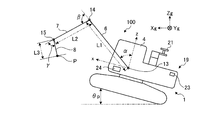
- FIG. 1 is a perspective view of a hydraulic excavator that is calibrated by the calibration system according to the present embodiment.
- FIG. 2-1 is a side view of the excavator.
- FIG. 2-2 is a rear view of the excavator.
- FIG. 2-3 is a top view of the excavator.
- FIG. 3 is a block diagram showing a configuration of a control system provided in the hydraulic excavator and a calibration system for the hydraulic excavator according to the present embodiment.
- FIG. 4 is a diagram showing a list of parameters necessary for calculating the blade edge position.
- FIG. 5 is a side view of the boom.
- FIG. 6 is a side view of the arm.
- FIG. 7 is a side view of the bucket and the arm.
- FIG. 1 is a perspective view of a hydraulic excavator that is calibrated by the calibration system according to the present embodiment.
- FIG. 2-1 is a side view of the excavator.
- FIG. 2-2 is
- FIG. 8 is a side view of the bucket.
- FIG. 9 is a diagram illustrating a method of calculating a parameter indicating the cylinder length.
- FIG. 10 is a flowchart showing a work procedure performed by the operator during calibration.
- FIG. 11 is a diagram illustrating an installation position of the external measurement device.
- FIG. 12 is a top view showing positions of three revolving bodies having different revolving angles.
- FIG. 13 is a side view showing the position of the cutting edge in the five postures of the work machine 2.
- FIG. 14 is a side view of the hydraulic excavator.
- FIG. 15 is a diagram illustrating the first position to the fifth position and the original first position to the fifth position when the excavator is tilted in the longitudinal direction of the vehicle body by the weight of the work implement 2.
- FIG. 16 is a top view showing the positions of the first measurement point and the second measurement point on the reference antenna.
- FIG. 17 is a top view showing the positions of the third measurement point and the fourth measurement point on the directional antenna.
- FIG. 18 is a diagram illustrating an example of an operation screen of the calibration apparatus.
- FIG. 19 is a functional block diagram illustrating processing functions related to calibration of the calculation unit.
- FIG. 20 is a side view of the hydraulic excavator.
- FIG. 21 is a diagram illustrating an example of a method for correcting the position of the blade edge measured by the external measurement device.
- FIG. 22 is a diagram illustrating a calculation method of coordinate conversion information.
- FIG. 23 is a diagram illustrating a calculation method of coordinate conversion information.
- FIG. 1 is a perspective view of a hydraulic excavator 100 that is calibrated by the calibration system according to the present embodiment.
- FIG. 2A is a side view of the excavator 100.
- FIG. 2-2 is a rear view of the excavator 100.
- FIG. 2-3 is a top view of the excavator 100.
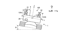
- FIG. 3 is a block diagram illustrating a configuration of a control system provided in the excavator 100 and a calibration system 200 of the excavator 100 according to the present embodiment.
- the hydraulic excavator 100 has a vehicle body 1 and a work implement 2.
- the vehicle body 1 includes a revolving body 3, a cab 4, and a traveling body 5.
- the turning body 3 is attached to the traveling body 5 so as to be turnable.
- the revolving unit 3 accommodates a hydraulic pump 37 (see FIG. 3) and devices such as an engine (not shown).
- a handrail 9 is attached to the upper part of the revolving body 3.
- the cab 4 is placed at the front of the revolving unit 3.
- a display input device 38 and an operation device 25 described later are arranged in the cab 4 (see FIG. 3).
- the traveling body 5 has crawler belts 5a and 5b, and the excavator 100 travels as the crawler belts 5a and 5b rotate.
- the working machine 2 is attached to the front portion of the vehicle body 1 and includes a boom 6, an arm 7, a bucket 8 as a working tool, a boom cylinder 10, an arm cylinder 11, and a bucket cylinder 12.
- a base end portion of the boom 6 is rotatably attached to a front portion of the vehicle body 1 via a boom pin 13. That is, the boom pin 13 corresponds to the rotation center of the boom 6 with respect to the swing body 3.
- a base end portion of the arm 7 is rotatably attached to a tip end portion of the boom 6 via an arm pin 14. That is, the arm pin 14 corresponds to the rotation center of the arm 7 with respect to the boom 6.
- a bucket 8 is rotatably attached to the tip of the arm 7 via a bucket pin 15. That is, the bucket pin 15 corresponds to the rotation center of the bucket 8 with respect to the arm 7.
- the length of the boom 6, that is, the length between the boom pin 13 and the arm pin 14 is L1, which corresponds to the first distance of the present embodiment.
- the length of the arm 7, that is, the length between the arm pin 14 and the bucket pin 15 is L2, which corresponds to the second distance of the present embodiment.
- the length of the bucket 8, that is, the length between the bucket pin 15 and the blade tip P of the bucket 8 is L3, which corresponds to the third distance of the present embodiment.
- the base end portion of the boom cylinder 10 is rotatably attached to the swing body 3 via a boom cylinder foot pin 10a.
- the tip of the boom cylinder 10 is rotatably attached to the boom 6 via a boom cylinder top pin 10b.
- the boom cylinder 10 drives the boom 6 by expanding and contracting by hydraulic pressure.
- the base end of the arm cylinder 11 is rotatably attached to the boom 6 via an arm cylinder foot pin 11a.
- the tip of the arm cylinder 11 is rotatably attached to the arm 7 via an arm cylinder top pin 11b.
- the arm cylinder 11 drives the arm 7 by expanding and contracting by hydraulic pressure.
- the base end portion of the bucket cylinder 12 is rotatably attached to the arm 7 via a bucket cylinder foot pin 12a.
- the tip of the bucket cylinder 12 is rotatably attached to one end of the first link member 47 and one end of the second link member 48 via the bucket cylinder top pin 12b.
- the other end of the first link member 47 is rotatably attached to the distal end portion of the arm 7 via the first link pin 47a.
- the other end of the second link member 48 is rotatably attached to the bucket 8 via a second link pin 48a.
- the bucket cylinder 12 drives the bucket 8 by expanding and contracting by hydraulic pressure.
- the boom 6, the arm 7, and the bucket 8 are provided with a first angle detection unit 16, a second angle detection unit 17, and a third angle detection unit 18, respectively.
- the first angle detection unit 16, the second angle detection unit 17, and the third angle detection unit 18 are, for example, stroke sensors, and detect the stroke length of each cylinder 10, 11, 12, and thereby the boom 6 with respect to the vehicle body 1.
- the rotation angle of the arm 7 with respect to the boom 6, and the rotation angle of the bucket 8 with respect to the arm 7 are indirectly detected.
- the first angle detector 16 detects the stroke length of the boom cylinder 10.
- the display controller 39 to be described later calculates the rotation angle ⁇ of the boom 6 with respect to the z axis of the vehicle body coordinate system shown in FIG. 2A from the stroke length of the boom cylinder 10 detected by the first angle detector 16.
- the second angle detector 17 detects the stroke length of the arm cylinder 11.
- the display controller 39 calculates the rotation angle ⁇ of the arm 7 with respect to the boom 6 from the stroke length of the arm cylinder 11 detected by the second angle detector 17.
- the third angle detector 18 detects the stroke length of the bucket cylinder 12.
- the display controller 39 calculates the rotation angle ⁇ of the bucket 8 relative to the arm 7 from the stroke length of the bucket cylinder 12 detected by the third angle detection unit 18. The calculation method of the rotation angles ⁇ , ⁇ , ⁇ will be described later.
- the vehicle body 1 is provided with a position detector 19.
- the position detector 19 detects the current position of the vehicle body 1 of the excavator 100.
- the position detector 19 includes two antennas 21 and 22 for the RTK-GNSS (Real Time Kinematic-Global Navigation Satellite Systems, GNSS refers to the global navigation satellite system) shown in FIG. 1, and 3 shown in FIG. A dimension position sensor 23.
- the antennas 21 and 22 are attached to the handrail 9 and are separated by a certain distance along a y-axis (see FIG. 2-3) of a vehicle body coordinate system xyz described later.
- the three-dimensional position sensor 23 detects the current positions of the antennas 21 and 22 in the global coordinate system Xg-Yg-Zg.
- the global coordinate system is a coordinate system measured by GNSS, and is a coordinate system based on the origin fixed on the earth.
- the vehicle body coordinate system to be described later is a coordinate system based on the origin fixed to the vehicle body 1 (specifically, the turning body 3).
- the antenna 21 (hereinafter referred to as the reference antenna 21) is an antenna for detecting the current position of the vehicle body 1.
- the antenna 22 (hereinafter referred to as a directional antenna 22) is an antenna for detecting the orientation of the vehicle body 1, specifically, the revolving structure 3.
- the position detector 19 detects the direction angle in the global coordinate system of the x-axis and y-axis of the vehicle body coordinate system, which will be described later, based on the positions of the reference antenna 21 and the direction antenna 22.
- the antennas 21 and 22 may be GPS (Global Positioning System) antennas.
- the vehicle body 1 is provided with an IMU (Inertial Measurement Unit) 24.
- the IMU 24 is installed below the cab 4 as shown in FIGS. 2-1 and 2-2.
- the IMU 24 detects acceleration and angular velocity acting on the excavator 100.
- the IMU 24 detects an inclination angle ⁇ r (hereinafter referred to as a roll angle ⁇ r) in the width direction of the vehicle body 1 with respect to the direction of gravity (vertical line).
- the width direction means the width direction of the bucket 8 and coincides with the vehicle width direction.
- the work implement 2 includes a tilt bucket described later as a work tool
- the width direction of the bucket 8 and the vehicle width direction may not match.
- the IMU 24 detects an inclination angle ⁇ p in the front-rear direction of the vehicle body 1 with respect to the direction of gravity (hereinafter referred to as a pitch angle ⁇ p as appropriate).
- the IMU 24 functions as a tilt information detection device that detects tilt information of the excavator 100 in the longitudinal direction of the vehicle body.
- the IMU 24 As a tilt information detection device, information necessary for controlling the excavator 100 such as acceleration, angular velocity, roll angle, etc. of the excavator 100 can be acquired by one device.
- a roll angle sensor and a pitch angle sensor may be prepared instead of the IMU 24, and the former may detect the roll angle ⁇ r and the latter may detect the pitch angle ⁇ p.
- the calibration system 200 of the excavator 100 includes the excavator 100 shown in FIG. 1, a calibration device 60, an external measurement device 62, and an IMU 24 as a tilt information detection device.
- the excavator 100 includes an operation device 25, a work machine controller 26, a work machine control device 27, and a hydraulic pump 37.
- the operating device 25 includes a work implement operation member 31, a work implement operation detection unit 32, a travel operation member 33, a travel operation detection unit 34, a turning operation member 51, and a turning operation detection unit 52.
- the work machine operation member 31 is a member for the operator of the excavator 100 to operate the work machine 2, and is, for example, an operation lever.
- the work machine operation detection unit 32 detects the operation content of the work machine operation member 31 and sends it to the work machine controller 26 as a detection signal.
- the traveling operation member 33 is a member for the operator to operate traveling of the excavator 100, and is, for example, an operation lever.
- the traveling operation detection unit 34 detects the operation content of the traveling operation member 33 and sends it to the work machine controller 26 as a detection signal.
- the turning operation member 51 is a member for the operator to turn the turning body 3 and is, for example, an operation lever.
- the turning operation detection unit 52 detects the operation content of the turning operation member 51 and sends it to the work machine controller 26 as a detection signal.
- the work machine controller 26 includes a storage unit 35 such as a RAM and a ROM, and a calculation unit 36 such as a CPU.
- the work machine controller 26 mainly controls the operation of the work machine 2 and the turning of the swing body 3.
- the work machine controller 26 generates a control signal for operating the work machine 2 in accordance with the operation of the work machine operation member 31, and outputs the control signal to the work machine control device 27.
- the work machine control device 27 includes a hydraulic control device such as a proportional control valve.
- the work machine control device 27 controls the flow rate of the hydraulic oil supplied from the hydraulic pump 37 to the hydraulic cylinders 10, 11, 12 based on the control signal from the work machine controller 26.
- the hydraulic cylinders 10, 11, and 12 are driven according to the hydraulic oil supplied from the work machine control device 27.
- the work machine controller 26 generates a control signal for turning the turning body 3 in accordance with the operation of the turning operation member 51 and outputs the control signal to the turning motor 49. As a result, the turning motor 49 is driven and the turning body 3 turns.
- a display system 28 is mounted on the excavator 100.
- the display system 28 is a system for providing an operator with information for excavating the ground in the work area and forming a shape like a design surface described later.
- the display system 28 includes a display input device 38 and a display controller 39.
- the display input device 38 includes a touch panel type input unit 41 and a display unit 42 such as an LCD.
- the display input device 38 displays a guidance screen for providing information for excavation. Various keys are displayed on the guidance screen. The operator can execute various functions of the display system 28 by touching various keys on the guidance screen. The guidance screen will be described later.
- the display controller 39 realizes various functions of the display system 28.
- the display controller 39 and the work machine controller 26 can communicate with each other by wireless or wired communication means.
- the display controller 39 includes a storage unit 43 such as a RAM and a ROM, and a calculation unit 44 such as a CPU.
- the calculation unit 44 executes various calculations for displaying the guidance screen based on various data stored in the storage unit 43 and the detection result of the position detection unit 19. Next, a method for calculating the blade edge position of the bucket 8 will be described in detail.
- FIG. 4 is a diagram showing a list of parameters necessary for calculating the blade edge position.
- the calculation unit 44 of the display controller 39 calculates the current position of the blade edge of the bucket 8 based on the detection result of the position detection unit 19 and a plurality of parameters stored in the storage unit 43.
- the parameters include work implement parameters and antenna parameters.
- the work implement parameters include a plurality of parameters indicating dimensions of the boom 6, the arm 7, and the bucket 8 and their rotation angles.
- the antenna parameters include a plurality of parameters indicating the positional relationship between the antennas 21 and 22 and the boom 6.
- the calculation unit 44 of the display controller 39 includes a first current position calculation unit 44a and a second current position calculation unit 44b.
- the first current position calculation unit 44a calculates the current position of the cutting edge of the bucket 8 in the vehicle body coordinate system based on the work implement parameter.
- the second current position calculation unit 44b includes the antenna parameters, the current position of the antennas 21 and 22 detected by the position detection unit 19 in the global coordinate system, and the vehicle body coordinates of the blade edge of the bucket 8 calculated by the first current position calculation unit 44a.
- the current position in the global coordinate system of the cutting edge of the bucket 8 is calculated from the current position in the system. Specifically, the current position of the blade edge of the bucket 8 is obtained as follows.
- a vehicle body coordinate system xyz whose origin is an intersection of an axis of the boom pin 13 and an operation plane of the work machine 2 described later is set.
- the position of the boom pin 13 means the position of the middle point of the boom pin 13 in the vehicle width direction.
- the coordinates (x, y, z) of the cutting edge of the bucket 8 in the vehicle body coordinate system are the rotation angles ⁇ , ⁇ , ⁇ of the boom 6, arm 7, and bucket 8, and the lengths of the boom 6, arm 7, and bucket 8.
- L1, L2, and L3 calculation is performed according to the following equation (1).
- the current rotation angles ⁇ , ⁇ , ⁇ of the boom 6, the arm 7, and the bucket 8 are calculated from the detection results of the first angle detector 16, the second angle detector 17, and the third angle detector 18. A method will be described.
- FIG. 5 is a side view of the boom 6.
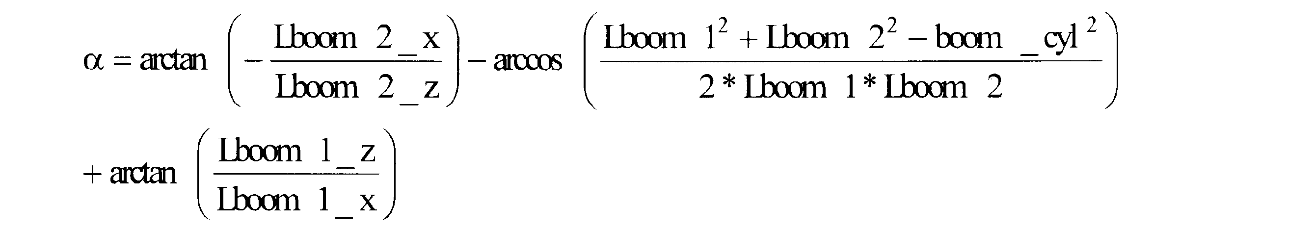
- the rotation angle ⁇ of the boom 6 is expressed by the following equation 2 using the work implement parameters shown in FIG.
- Lroom2_x is the distance in the horizontal direction of the vehicle body 2 to which the boom 6 is attached between the boom cylinder foot pin 10a and the boom pin 13, that is, the direction corresponding to the x-axis direction of the vehicle body coordinate system.
- Lroom2_z is a distance in a direction corresponding to the vertical direction of the vehicle body 2 to which the boom 6 is attached between the boom cylinder foot pin 10a and the boom pin 13, that is, the z-axis direction of the vehicle body coordinate system.
- Lroom1 is the distance between the boom cylinder top pin 10b and the boom pin 13.
- Lboom2 is the distance between the boom cylinder foot pin 10a and the boom pin 13.
- boom_cyl is the distance between the boom cylinder foot pin 10a and the boom cylinder top pin 10b.
- Lroom1_z is the distance in the zoom axis direction between the boom cylinder top pin 10b and the boom pin 13. Note that the direction connecting the boom pin 13 and the arm pin 14 in a side view is the xboom axis, and the direction perpendicular to the xboom axis is the zboom axis.
- Lroom1_x is a distance in the xroom axis direction between the boom cylinder top pin 10b and the boom pin 13.
- FIG. 6 is a side view of the arm 7.
- the rotation angle ⁇ of the arm 7 is expressed by the following equation 3 using the work implement parameters shown in FIGS. 5 and 6.
- Lroom3_z is a distance in the z boom axis direction between the arm cylinder foot pin 11a and the arm pin 14.
- Lroom3_x is the distance in the xroom axis direction between the arm cylinder foot pin 11a and the arm pin 14.
- Lroom3 is a distance between the arm cylinder foot pin 11a and the arm pin 14.
- Larm2 is the distance between the arm cylinder top pin 11b and the arm pin 14.
- arm_cyl is the distance between the arm cylinder foot pin 11a and the arm cylinder top pin 11b.
- Larm2_x is a distance in the xarm2 axial direction between the arm cylinder top pin 11b and the arm pin 14.
- Larm2_z is a distance in the zarm2 axial direction between the arm cylinder top pin 11b and the arm pin 14.
- the direction connecting the arm cylinder top pin 11b and the bucket pin 15 is the xarm2 axis
- the direction perpendicular to the xarm2 axis is the zar2 axis.
- Larm1_x is a distance in the xarm2 axial direction between the arm pin 14 and the bucket pin 15.
- Larm1_z is the distance in the zarm2 axial direction between the arm pin 14 and the bucket pin 15.
- the direction connecting the arm pin 14 and the bucket pin 15 in a side view is defined as an xarm1 axis.
- the rotation angle ⁇ of the arm 7 is an angle formed between the xboom axis and the xarm1 axis.
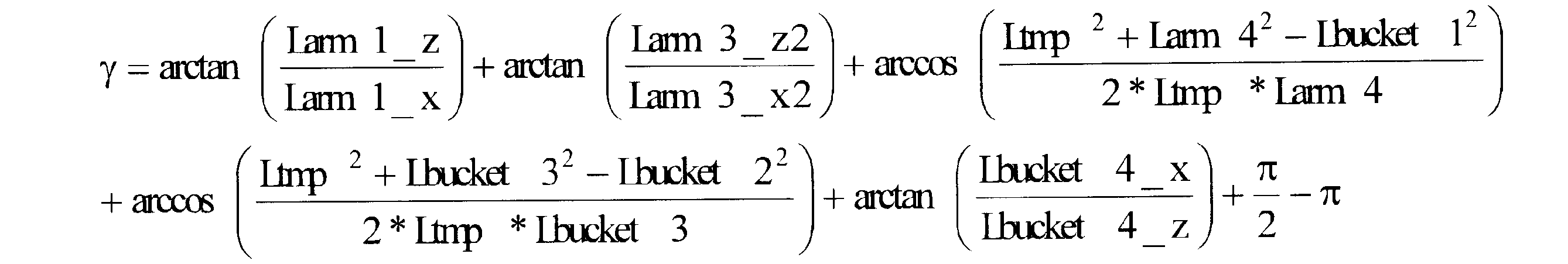
- FIG. 7 is a side view of the bucket 8 and the arm 7.
- FIG. 8 is a side view of the bucket 8.
- FIG. 9 is a diagram illustrating a method of calculating a parameter indicating the cylinder length.
- the rotation angle ⁇ of the bucket 8 is expressed by the following equation (4) using the work implement parameters shown in FIGS.
- Larm3_z2 is a distance in the zarm2 axial direction between the first link pin 47a and the bucket pin 15.
- Larm3_x2 is the distance in the xarm2 axial direction between the first link pin 47a and the bucket pin 15.
- Ltmp is a distance between the bucket cylinder top pin 12 b and the bucket pin 15.
- Lam4 is the distance between the first link pin 47a and the bucket pin 15.
- Lbucket 1 is a distance between the bucket cylinder top pin 12b and the first link pin 47a.
- Lbucket 3 is a distance between the bucket pin 15 and the second link pin 48a.
- Lbucket 2 is a distance between the bucket cylinder top pin 12b and the second link pin 48a.
- Lbucket4_x is the distance in the xbucket axis direction between the bucket pin 15 and the second link pin 48a.
- Lbucket4_z is a distance in the zbucket axis direction between the bucket pin 15 and the second link pin 48a.
- the direction connecting the bucket pin 15 and the blade tip P of the bucket 8 is the xbucket axis
- the direction perpendicular to the xbucket axis is the zbucket axis.
- the rotation angle ⁇ of the bucket 8 is an angle formed between the xbucket axis and the xarm1 axis.
- the aforementioned Ltmp is expressed by the following equation (5).
- Lam3_x1 is a distance in the xarm2 axial direction between the bucket cylinder foot pin 12a and the bucket pin 15.
- Lam3_z1 is the distance in the zarm2 axial direction between the bucket cylinder foot pin 12a and the bucket pin 15.
- the boom_cyl described above is a value obtained by adding the boom cylinder minimum length b_min and the boom cylinder offset bottom to the stroke length bss of the boom cylinder 10 detected by the first angle detector 16 as shown in FIG.
- arm_cyl is a value obtained by adding the minimum length a_min of the arm cylinder and the arm cylinder offset aft to the stroke length ass of the arm cylinder 11 detected by the second angle detector 17.
- bucket_cyl is a value obtained by adding the minimum length bk_min of the bucket cylinder 12 and the bucket cylinder offset bkoft to the stroke length bkss of the bucket cylinder 12 detected by the third angle detector 18.
- the calibration device 60 is a device for calibrating the parameters necessary for calculating the rotation angles ⁇ , ⁇ , ⁇ and the position of the blade edge of the bucket 8 in the excavator 100.
- the calibration device 60 can perform data communication with the display controller 39 by wire or wirelessly.
- the calibration device 60 calibrates the parameters shown in FIG. 4 based on the information measured by the external measurement device 62.
- the parameter calibration is executed, for example, at the time of shipment of the excavator 100 or at the initial setting after maintenance.
- FIG. 10 is a flowchart showing an operation procedure performed by the operator during calibration.
- FIG. 11 is a diagram showing the installation position of the external measuring device 62.
- FIG. 12 is a top view showing the positions of the three revolving bodies 3 having different turning angles.
- step S2 the operator inputs the bucket information to the input unit 63 of the calibration device 60 shown in FIG.
- the bucket information is information related to the dimensions of the bucket 8.
- the bucket information includes the distance in the xbucket axis direction between the bucket pin 15 and the second link pin 48a (Lbucket4_x) and the distance in the zbucket axis direction between the bucket pin 15 and the second link pin 48a (Lbucket4_z).
- the operator inputs design values or values measured by measuring means such as a measure tape as bucket information.
- step S3 the operator measures the positions of the three revolving bodies 3 having different turning angles.
- the operator operates the turning operation member 51 shown in FIG. 3 to turn the turning body 3.
- the posture of the work machine 2 is maintained in a fixed state.
- the operator uses the external measuring device 62 to measure the position of the prism 62P attached below the counterweight WT of the revolving structure 3 using the external measuring device 62.
- the positions of the three prisms 62P having different turning angles are measured as the positions of the turning body 3 (hereinafter referred to as the first turning position P21, the second turning position P22, and the third turning position P23).
- the positions of three cutting edges having different turning angles may be measured as the position of the turning body 3. Also in this case, the posture of the work machine 2 is maintained in a fixed state.
- step S4 the operator inputs the revolving unit position information to the input unit 63 of the calibration device 60.
- the turning body position information includes coordinates indicating the first turning position P21, the second turning position P22, and the third turning position P23 measured by the operator using the external measuring device 62 in step S3.
- step S5 the operator measures the center position of the side surface of the boom pin 13 using the external measuring device 62.
- the coordinate system of the external measuring device 62 is the earth gravity coordinate system XYZ.
- the Z-axis direction coincides with the direction of gravity action.
- the X-axis direction and the Y-axis direction are orthogonal to the Z-axis direction, and the X-axis direction and the Y-axis direction are orthogonal to each other.
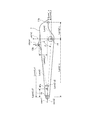
- FIG. 13 is a side view showing the position of the cutting edge in the five postures of the work machine 2.
- the operator measures the position of the blade edge in the five postures of the work machine 2 using the external measuring device 62 shown in FIG. 11.
- the operator operates the work implement operating member 31 shown in FIG. 3 to move the position of the blade edge of the bucket 8 to five positions from the first position P1 to the fifth position P5 shown in FIG.
- the first position P1 to the fifth position P5 correspond to the positions of the work points.
- the revolving structure 3 is not revolved and the state fixed with respect to the traveling body 5 is maintained.
- the operator measures the coordinates of the blade edge at each position from the first position P1 to the fifth position P5 using the external measuring device 62.
- the first position P1 and the second position P2 are different positions in the vehicle front-rear direction on the ground GD.
- the third position P3 and the fourth position P4 are different positions in the longitudinal direction of the vehicle body in the air.
- the third position P3 and the fourth position P4 are positions that are different in the vertical direction with respect to the first position P1 and the second position P2.
- the fifth position P5 is a position between the first position P1, the second position P2, the third position P3, and the fourth position P4.
- FIG. 14 is a side view of the excavator 100.
- FIG. 15 is a diagram illustrating the first position PS1 to the fifth position PS5 and the original first position P1 to the fifth position P5 when the excavator 100 is tilted in the longitudinal direction of the vehicle body due to the weight of the work implement 2.
- step S6 when the external measurement device 62 measures the cutting edge position P in five postures in which the posture of the working machine 2 is changed, the position of the cutting edge from the assumed position due to the inclination in the vehicle longitudinal direction due to the weight of the working machine 2 is determined. P shifts. For this reason, the accuracy of calibration may be reduced. Specifically, as shown in FIG.
- the position PS of the cutting edge measured by the external measuring device 62 is the original cutting edge position. Lower than P. Therefore, the first position PS1 to the fifth position PS5 measured by the external measuring device 62 are lower than the original first position P1 to the fifth position P5, as shown in FIG.
- the excavator 100 tilts in the longitudinal direction of the vehicle body due to the weight of the work implement 2, the excavator 100 tilts around the lower side of the wheel 5 ⁇ / b> F on the work implement 2 side of the traveling body 5, for example, as shown in FIG. 14. .
- the attitude angle of the excavator 100 that is, the pitch angle is ⁇ p.
- the pitch angle ⁇ p is used as the tilt information in the longitudinal direction of the vehicle body of the hydraulic excavator, and the first position PS1 to the fifth position PS5 measured by the external measuring device 62, that is, the plurality of positions of the work points, It correct
- a calibration value of a parameter necessary for calculating the blade edge position is calculated. By doing in this way, the precision fall at the time of measuring the position of the blade edge in the height direction of excavator 100 is controlled.
- the calibration is performed using the corrected value, thereby suppressing a decrease in calibration accuracy.
- the correction of the position of the cutting edge measured by the external measuring device 62 will be described later.
- step S7 the operator inputs work implement position information to the input unit 63 of the calibration device 60.
- the work machine position information indicates coordinates from the first position P1 to the fifth position P5 of the cutting edge of the bucket 8 measured by the external measuring device 62.
- the operator inputs the coordinates from the first position P1 to the fifth position P5 of the cutting edge of the bucket 8 measured using the external measuring device 62 in step S6 to the input unit 63 of the calibration device 60.
- FIG. 16 is a top view showing the positions of the first measurement point and the second measurement point on the reference antenna.
- FIG. 17 is a top view showing the positions of the third measurement point and the fourth measurement point on the directional antenna.
- the operator measures the positions of the antennas 21 and 22 using the external measurement device 62.
- the operator measures the positions of the first measurement point P ⁇ b> 11 and the second measurement point P ⁇ b> 12 on the reference antenna 21 using the external measurement device 62.
- the first measurement point P11 and the second measurement point P12 are arranged symmetrically with respect to the center of the upper surface of the reference antenna 21.
- the shape of the upper surface of the reference antenna 21 is a rectangle or a square
- the first measurement point P11 and the second measurement point P12 are diagonal on the upper surface of the reference antenna 21. Two points.
- the operator measures the positions of the third measurement point P13 and the fourth measurement point P14 on the directional antenna 22 using the external measurement device 62.
- the third measurement point P13 and the fourth measurement point P14 are arranged symmetrically with respect to the center of the upper surface of the directional antenna 22. Similar to the first measurement point P11 and the second measurement point P12, the third measurement point P13 and the fourth measurement point P14 are two diagonal points on the upper surface of the directional antenna 22. It is preferable that a mark is attached to the first measurement point P11 to the fourth measurement point P14 in order to facilitate measurement.
- a bolt or the like included as a component of the antennas 21 and 22 may be used as a mark.
- step S9 the operator inputs the antenna position information to the input unit of the calibration device 60 shown in FIG.
- the antenna position information includes coordinates indicating the positions of the first measurement point P11 to the fourth measurement point P14 measured by the operator using the external measurement device 62 in step S6.
- step S10 the operator instructs the calibration device 60 shown in FIG. 3 to execute calibration.
- the calibration device 60 includes an input unit 63, a display unit 64, and a calculation unit 65.
- the input unit 63 is a part to which the work implement position information, the swing body position information, the antenna position information, and the bucket information described above are input.
- the input unit 63 has a configuration for an operator to manually input the above-described information, and has, for example, a plurality of keys.
- the input unit 63 may be a touch panel type as long as a numerical value can be input.
- the display unit 64 is, for example, an LCD, and is a part on which an operation screen for performing calibration is displayed.
- FIG. 18 is a diagram illustrating an example of an operation screen of the calibration device 60.
- an input field 66 for inputting the above-described information is displayed on the operation screen 42D of the display unit 42.
- the operator operates the input unit 63 to input the above-described information in the input field 66 of the operation screen.
- the information input to the input field 66 includes, for example, the coordinates of the first position P1 to the fifth position P5 measured by the external measuring device 62 and the IMU 24 shown in FIGS. 2-1 to 2-3 and FIG.
- FIG. 19 is a functional block diagram showing processing functions related to the calibration of the calculation unit 65.
- the computing unit 65 executes a process for calibrating the parameters based on the information input via the input unit 63.
- the calculation unit 65 includes a vehicle body coordinate system calculation unit 65a, a coordinate conversion unit 65b, a first calibration calculation unit 65c, a second calibration calculation unit 65d, and a correction unit 65e.
- FIG. 20 is a side view of the excavator 100.
- FIG. 21 is a diagram illustrating an example of a method for correcting the position PS of the blade edge measured by the external measuring device 62.
- the correcting unit 65e corrects the position PS of the blade edge measured by the external measuring device 62 based on the pitch angle ⁇ p.
- the work machine position information MI that is, the first position PS to the fifth position PS5 measured by the external measuring device 62 are under the influence of the weight of the work machine 2 and are lower than the original position. Therefore, the correction unit 65e corrects the first position PS to the fifth position PS5 using the pitch angle ⁇ p so that the original position P1 is changed to the fifth position P5.
- the excavator 100 is inclined in the longitudinal direction of the vehicle body around the lower side of the wheel 5F on the work machine 2 side of the traveling body 5, and the center of the inclination is a position CP.
- a pitch angle when the excavator 100 is inclined in the longitudinal direction of the vehicle body is defined as ⁇ p.
- the boom pin 13 rotates about the position CP.
- the position of the boom pin 13 when the excavator 100 is tilted in the longitudinal direction of the vehicle body is indicated by reference numeral 13S.
- the work implement 2 also rotates about the position CP.
- the cutting edge changes from the position P to the position PS.
- the coordinates of the position CP are (XC0, ZC0).
- Xc-Zc with the position CP as the origin.
- the coordinates of the origin of the coordinate system Xc-Zc that is, the coordinates (Xc0, Zc0) of the position CP are Xc0 in the X-axis direction and Zc0 in the Y-axis direction from the origin O (0, 0) of the gravity coordinate system XZ of the earth. Only a distance away.
- the coordinates of the position PS of the cutting edge measured by the external measuring device 62 in the earth's gravity coordinate system XZ (Xc ′, Zc ′), and the cutting edge position at the original position of the work machine 2 in the earth's gravity coordinate system XZ.
- the coordinates at the position P are (Xc, Yc).
- the position P of the blade edge is the position CP, that is, the position obtained by rotating the blade edge position PS upward U by the pitch angle ⁇ p with the origin of the coordinate system Xc-Zc as the center.
- the coordinates (Xc, Yc) of the cutting edge position P are centered on the origin of the coordinate system Xc-Zc with the coordinates (Xc ′, Zc ′) of the cutting edge position PS measured by the external measuring device 62 as the origin. It can obtain
- the position P of the blade edge in the coordinate system with the position CP as the origin is defined as coordinates (xc, zc).
- the cutting edge position PS with the position CP as the origin is coordinates (Xc′ ⁇ Xc0, Zc′ ⁇ Zc0). It becomes. Therefore, the coordinates (xc, zc) of the position P of the cutting edge in the coordinate system with the position CP as the origin can be obtained by Equation (6).
- the coordinates (Xc, Zc) of the position P of the cutting edge in the gravity coordinate system XZ of the earth are coordinated using the coordinates (xc, zc) obtained by Equation 6 and the coordinates (Xc0, Zc0) of the position CP. (Xc0 + xc, Zc0 + zc).
- the center of the inclination is not limited to the position CP, but may be another position.
- the center position of the turning axis connecting the turning body 3 and the traveling body 5 may be set as the center of inclination.
- the correcting unit 65e corrects the first position PS1 to the fifth position PS5 measured by the external measuring device 62 using the formula 6 and the pitch angle ⁇ p.
- the correction unit 65e outputs the corrected first position PS1 to fifth position PS5 to the vehicle body coordinate system calculation unit 65a of the calculation unit 65 shown in FIG. 19 as corrected work machine position information MIC.
- the correction unit 65e corrects the first position PS1 to the fifth position PS5 measured by the external measuring device 62 so as to be the original first position P1 to the fifth position P5. A decrease in accuracy when the position of the blade edge in the vertical direction is measured is suppressed.
- the vehicle body coordinate system calculation unit 65a calculates coordinate conversion information based on the post-correction work machine position information MIC and the turning body position information RI input by the input unit 63.
- the coordinate conversion information is information for converting a coordinate system based on the external measuring device 62 into a vehicle body coordinate system. Since the above-described corrected work machine position information MIC (work machine position information MI) and antenna position information AI are measured by the external measurement device 62, the gravity coordinate system of the earth based on the external measurement device 62 is used. It is represented by XYZ.
- the coordinate conversion information TI is information for converting the corrected work machine position information MIC and the antenna position information AI from the earth's gravitational coordinate system to the vehicle body coordinate system xyz based on the external measuring device 62. is there. Next, a method for calculating the coordinate conversion information TI will be described.
- 22 and 23 are diagrams showing a calculation method of coordinate conversion information.
- the vehicle body coordinate system calculation unit 65a calculates a first unit normal vector AH perpendicular to the operation plane A of the work implement 2 based on the corrected work implement position information MIC.
- the vehicle body coordinate system calculation unit 65a calculates the operation plane of the work implement 2 from the five positions included in the corrected work implement position information MIC using the least square method, and calculates the first unit normal vector AH based on the operation plane.
- the first unit normal vector AH is represented by two vectors a1 and a2 obtained from the coordinates of three positions that do not deviate from the other two positions among the five positions included in the corrected work machine position information MIC. It may be calculated based on this.
- the vehicle body coordinate system calculation unit 65a calculates a second unit normal vector perpendicular to the turning plane B of the turning body 3 based on the turning body position information RI. Specifically, the vehicle body coordinate system calculation unit 65a applies two vectors b1 and b2 obtained from the coordinates of the first turning position P21, the second turning position P22, and the third turning position P23 included in the turning body position information RI. Based on this, a second unit normal vector BH ′ perpendicular to the turning plane B ′ is calculated. Next, as shown in FIG. 19, the vehicle body coordinate system calculation unit 65a calculates the intersection vector DAB between the operation plane A of the work implement 2 and the turning plane B '.
- the vehicle body coordinate system calculation unit 65a calculates the unit normal vector of the plane B that passes through the intersection line vector DAB and is perpendicular to the operation plane A of the work machine 2 as the corrected second unit normal vector BH. Then, the vehicle body coordinate system calculation unit 65a calculates a third unit normal vector CH perpendicular to the first unit normal vector AH and the corrected second unit normal vector BH.
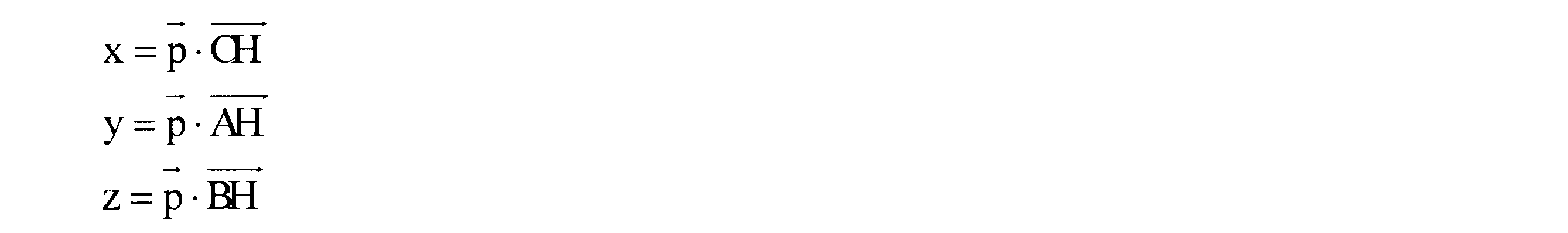
- the coordinate conversion unit 65b is a coordinate system in the external measurement device 62, which is measured by the external measurement device 62 and corrected by the correction unit 65e, using the post-correction work machine position information MIC and the antenna position information AI.
- XYZ is converted into the vehicle body coordinate system xyz) in the excavator 100.
- the coordinate conversion information includes the first unit normal vector AH, the corrected second unit normal vector BH, and the third unit normal vector CH. Specifically, as shown in the following Equation 7, the inner product of the coordinates in the coordinate system of the external measuring device 62 indicated by the vector p and the normal vectors AH, BH, and CH of the coordinate conversion information. Coordinates in the vehicle body coordinate system are calculated.
- the first calibration calculation unit 65c calculates the calibration value of the parameter by using numerical analysis based on the corrected work machine position information MIC converted into the vehicle body coordinate system. Specifically, as shown in the following equation 8, the calibration value of the parameter is calculated by the least square method.
- (X1, z1) are the coordinates of the first position P1 in the vehicle body coordinate system.
- (X2, z2) are the coordinates of the second position P2 in the vehicle body coordinate system.
- (X3, z3) are the coordinates of the third position P3 in the vehicle body coordinate system.
- X4, z4) are the coordinates of the fourth position P4 in the vehicle body coordinate system.
- (X5, z5) are the coordinates of the fifth position P5 in the vehicle body coordinate system.
- the second calibration calculation unit 65d calibrates the antenna parameter based on the antenna position information AI input to the input unit 63. Specifically, the second calibration calculation unit 65d calculates the coordinates of the midpoint between the first measurement point P11 and the second measurement point P12 as the coordinates of the position of the reference antenna 21. Specifically, the coordinates of the position of the reference antenna 21 are the distance Lbbx in the x-axis direction of the vehicle body coordinate system between the boom pin 13 and the reference antenna 21 and the vehicle body coordinate system between the boom pin 13 and the reference antenna 21. Is expressed by a distance Lbby in the y-axis direction and a distance Lbbz in the z-axis direction of the vehicle body coordinate system between the boom pin 13 and the reference antenna 21.
- the second calibration calculation unit 65d calculates the coordinates of the midpoint between the third measurement point P13 and the fourth measurement point P14 as the coordinates of the position of the direction antenna 22.
- the coordinates of the position of the directional antenna 22 are the distance Ldbx in the x-axis direction of the vehicle body coordinate system between the boom pin 13 and the directional antenna 22 and the coordinate of the vehicle body coordinate system between the boom pin 13 and the directional antenna 22.
- the distance Ldby in the y-axis direction and the distance Lbbz in the z-axis direction of the vehicle body coordinate system between the boom pin 13 and the direction antenna 22 are represented.
- the second calibration calculation unit 65d outputs the coordinates of the positions of the antennas 21 and 22 as calibration values of the antenna parameters Lbbx, Lbby, Lbbz, Lbdx, Lbdy, and Lbdz.
- the work implement parameter calculated by the first calibration calculation unit 65c, the antenna parameter calculated by the second calibration calculation unit 65d, and the bucket information are stored in the storage unit 43 of the display controller 39, and the cutting edge position described above is stored. Used for calculation.
- the coordinates at a plurality of positions of the cutting edge of the bucket 8 measured by the external measuring device 62 are converted into the vehicle body coordinate system. Then, based on the coordinates at a plurality of positions of the cutting edge of the bucket 8 converted into the vehicle body coordinate system, the calibration value of the parameter is automatically calculated by numerical analysis. For this reason, the number of parameters that require actual measurement can be reduced. Further, at the time of calibration, it is not necessary to adjust the parameter values until the measured value and the calculated value of the position coordinates of the cutting edge of the bucket 8 coincide. For this reason, in the calibration system 200 of the excavator 100, the accuracy of detecting the position of the blade edge can be improved and the calibration operation time can be shortened.
- the unit normal vector BH ′ perpendicular to the turning plane B ′ specified from the turning body position information RI is not used as the second unit normal vector.
- an intersection vector DAB between the operation plane A of the work implement 2 and the turning plane B ′ of the turning body 3 is calculated.
- the unit normal vector BH of the plane B that passes through the intersection line vector DAB and is perpendicular to the operation plane A of the work machine 2 is calculated as the second unit normal vector.
- the post-correction work machine position information MIC includes the coordinates of the first position P1 to the fifth position P5 in which the position of the work machine 2 in the vertical direction and the position in the longitudinal direction of the vehicle body are different. Since coordinates at various positions are used in this way, coordinate conversion information can be calculated with high accuracy. Furthermore, since the work implement position information MI measured by the external measuring device 62 is corrected in consideration of the inclination of the excavator 100 in the longitudinal direction of the vehicle body, the post-correction work implement position information MIC is the original position of the cutting edge. Is closer to the value.
- the work machine 2 includes the boom 6, the arm 7, and the bucket 8, but the work tool attached to the work machine 2 is not limited to the bucket 8.
- the cutting edge of the bucket 8 is illustrated as the work point.
- the work point is a part that contacts the work object such as a point located at the tip of the work tool. May be.
- the rotation angles ⁇ , ⁇ , ⁇ of the boom 6, the arm 7, and the bucket 8 may be directly detected by an angle sensor.
- the pitch angle ⁇ p may be obtained from the detection result using, for example, a level attached to the counterweight WT of the excavator 100 as an inclination information detection device.
- a pressure sensor may be provided on the boom 6 to determine the moment of the work implement 2, and the tilt information in the longitudinal direction of the hydraulic excavator 100, for example, the pitch angle ⁇ p may be determined from the obtained moment.
- the work machine position information MI is not limited to the coordinates of the five positions of the blade edge of the bucket 8 described above.
- the work machine position information MI may be any information that includes the positions of at least three work points with different postures of the work machine 2.
- the positions of the three work points are not arranged in a straight line, but if the position of one work point is separated in the vertical direction or the vehicle body longitudinal direction with respect to the straight line connecting the other two work points. Good.
- the work machine position information MI, the revolving structure position information RI, and the antenna position information AI may be input from the external measurement device 62 to the input unit 63 of the calibration device 60 by wired or wireless communication means.
- the external measuring device 62 is not limited to the total station, and may be another device that measures the position of the work point.
- the unit normal vector BH obtained by correcting the unit normal vector BH ′ perpendicular to the turning plane B ′ specified from the revolving body position information RI is used as the coordinate conversion information.
- BH ′ may be used as coordinate conversion information.
Landscapes
- Engineering & Computer Science (AREA)
- Radar, Positioning & Navigation (AREA)
- Remote Sensing (AREA)
- Mining & Mineral Resources (AREA)
- Structural Engineering (AREA)
- General Engineering & Computer Science (AREA)
- Civil Engineering (AREA)
- Mechanical Engineering (AREA)
- General Physics & Mathematics (AREA)
- Physics & Mathematics (AREA)
- Computer Networks & Wireless Communication (AREA)
- Operation Control Of Excavators (AREA)
- Component Parts Of Construction Machinery (AREA)
- Position Fixing By Use Of Radio Waves (AREA)
Abstract
Description
図1は、本実施形態に係る較正システムによる較正が行われる油圧ショベル100の斜視図である。図2-1は、油圧ショベル100の側面図である。図2-2は、油圧ショベル100の背面図である。図2-3は、油圧ショベル100の上面図である。図3は、油圧ショベル100が備える制御系の構成及び本実施形態に係る油圧ショベル100の較正システム200を示すブロック図である。
油圧ショベル100には、表示システム28が搭載されている。表示システム28は、作業エリア内の地面を掘削して、後述する設計面のような形状に形成するための情報をオペレータに提供するためのシステムである。表示システム28は、表示入力装置38と、表示コントローラ39とを有している。
図4は、刃先位置を算出するために必要となるパラメータのリストを示す図である。表示コントローラ39の演算部44は、位置検出部19の検出結果及び記憶部43に記憶されている複数のパラメータに基づいて、バケット8の刃先の現在位置を演算する。パラメータは、作業機パラメータと、アンテナパラメータとを含む。作業機パラメータは、ブーム6とアーム7とバケット8との寸法及びこれらの回動角を示す複数のパラメータを含む。アンテナパラメータは、アンテナ21、22とブーム6との位置関係を示す複数のパラメータを含む。
図5は、ブーム6の側面図である。ブーム6の回動角αは、図5に示されている作業機パラメータを用いて、次の数2式によって表される。


較正装置60は、油圧ショベル100において、前述した回動角α、β、γの演算及びバケット8の刃先の位置を演算するために必要なパラメータを較正するための装置である。また、較正装置60は、有線又は無線によって表示コントローラ39とデータ通信を行うことができる。較正装置60は、外部計測装置62によって計測された情報に基づいて図4に示すパラメータを較正する。パラメータの較正は、例えば、油圧ショベル100の出荷時又はメンテナンス後の初期設定において実行される。


3 旋回体
5 走行体
6 ブーム
7 アーム
8 バケット(作業具)
60 較正装置
63 入力部
62 外部計測装置
65a 車体座標系演算部
65b 座標変換部
65c 第1較正演算部
65d 第2較正演算部
65e 補正部
100 油圧ショベル
Claims (5)
- 走行体と、前記走行体に旋回可能に取り付けられた旋回体と、前記旋回体に回動可能に取り付けられたブームと前記ブームに回動可能に取り付けられたアームと前記アームに回動可能に取り付けられた作業具とを含む作業機と、前記ブームと前記アームと前記作業具との寸法と、前記旋回体に対する前記ブームの回動角と、前記ブームに対する前記アームの回動角と、前記アームに対する前記作業具の回動角とを示す複数のパラメータに基づいて前記作業具に含まれる作業点の現在位置を演算する現在位置演算部と、を含む油圧ショベルと、
前記パラメータを較正するための較正装置と、
前記作業点の位置を計測する外部計測装置と、
前記油圧ショベルの車体前後方向における傾斜情報を検出する傾斜情報検出装置と、を備え、
前記較正装置は、
前記傾斜情報検出装置によって検出された前記油圧ショベルの車体前後方向における傾斜情報に基づいて、前記外部計測装置によって計測された前記作業点の複数の位置を補正し、補正後の前記作業点の複数の位置での座標に基づいて、前記パラメータの較正値を演算する、油圧ショベルの較正システム。 - 走行体と、前記走行体に旋回可能に取り付けられた旋回体と、前記旋回体に回動可能に取り付けられたブームと前記ブームに回動可能に取り付けられたアームと前記アームに回動可能に取り付けられた作業具とを含む作業機と、前記旋回体に対する前記ブームの回動角と前記ブームに対する前記アームの回動角と前記アームに対する前記作業具の回動角とを検出する角度検出部と、前記ブームと前記アームと前記作業具との寸法と前記回動角とを示す複数のパラメータに基づいて前記作業具に含まれる作業点の現在位置を演算する現在位置演算部と、を含む油圧ショベルと、
前記パラメータを較正するための較正装置と、
前記作業点の位置を計測する外部計測装置と、
前記油圧ショベルの車体前後方向における傾斜情報を検出する傾斜情報検出装置と、を備え、
前記較正装置は、
前記外部計測装置が計測した、前記作業機の姿勢が異なる少なくとも3つの前記作業点の位置を含む作業機位置情報と、前記旋回体の前記走行体に対する旋回角度が異なる少なくとも3つの前記作業点の位置を含む旋回体位置情報と、前記傾斜情報検出装置によって検出された、前記作業機位置情報に含まれるそれぞれの前記作業点に対応した、前記油圧ショベルの車体前後方向における傾斜情報と、が入力される入力部と、
前記傾斜情報に基づいて前記作業機位置情報に含まれるそれぞれの前記作業点の位置を補正する補正部と、
補正後の前記作業点を含む前記作業機位置情報に基づいて前記作業機の動作平面に垂直な第1単位法線ベクトルを演算し、前記旋回体位置情報に基づいて前記旋回体の旋回平面に垂直な第2単位法線ベクトルを演算し、前記第1単位法線ベクトルと前記第2単位法線ベクトルとに垂直な第3単位法線ベクトルを演算する車体座標系演算部と、
前記外部計測装置で計測された前記作業点の複数の位置での座標を、前記第1単位法線ベクトルと前記第2単位法線ベクトルと前記第3単位法線ベクトルとを用いて、前記外部計測装置における座標系から前記油圧ショベルにおける車体座標系に変換する座標変換部と、
前記車体座標系に変換された前記作業点の複数の位置での座標に基づいて、前記パラメータの較正値を演算する較正演算部と、
を含む、油圧ショベルの較正システム。 - 前記傾斜情報は、前記油圧ショベルのピッチ角である、請求項1又は請求項2に記載の油圧ショベルの較正システム。
- 走行体と、前記走行体に旋回可能に取り付けられた旋回体と、前記旋回体に回動可能に取り付けられたブームと前記ブームに回動可能に取り付けられたアームと前記アームに回動可能に取り付けられた作業具とを含む作業機と、を含む油圧ショベルにおいて、前記ブームと前記アームと前記作業具との寸法と前記回動角とを示す複数のパラメータを較正するための方法であって、
前記油圧ショベルの車体前後方向における傾斜情報を取得し、
前記傾斜情報に基づいて、前記作業具に含まれる前記作業点の複数の位置を補正し、
補正後の前記作業点の複数の位置での座標に基づいて、前記パラメータの較正値を演算する、油圧ショベルの較正方法。 - 走行体と、前記走行体に旋回可能に取り付けられた旋回体と、前記旋回体に回動可能に取り付けられたブームと前記ブームに回動可能に取り付けられたアームと前記アームに回動可能に取り付けられた作業具とを含む作業機と、を含む油圧ショベルにおいて、前記ブームと前記アームと前記作業具との寸法と前記回動角とを示す複数のパラメータを較正するための方法であって、
前記作業機の姿勢が異なる少なくとも2つの前記作業点の位置と前記作業機の動作平面上の所定の基準点の位置とを含む、又は前記作業機の姿勢が異なる少なくとも3つの、前記作業具に含まれる作業点の位置を含む作業機位置情報と、前記旋回体の前記走行体に対する旋回角度が異なる少なくとも3つの前記作業点の位置を含む旋回体位置情報と、前記作業機位置情報に含まれるそれぞれの前記作業点に対応した、前記油圧ショベルの車体前後方向における傾斜情報とを取得し、
前記傾斜情報に基づいて前記作業機位置情報に含まれるそれぞれの前記作業点の位置を補正し、
補正後の前記作業点を含む前記作業機位置情報に基づいて前記作業機の動作平面に垂直な第1単位法線ベクトルを演算し、前記旋回体位置情報に基づいて前記旋回体の旋回平面に垂直な第2単位法線ベクトルを演算し、前記第1単位法線ベクトルと前記第2単位法線ベクトルとに垂直な第3単位法線ベクトルを演算し、
前記作業点の複数の位置での座標を、前記第1単位法線ベクトルと前記第2単位法線ベクトルと前記第3単位法線ベクトルとを用いて、前記外部計測装置における座標系から前記油圧ショベルにおける車体座標系に変換し、
前記車体座標系に変換された前記作業点の複数の位置での座標に基づいて、前記パラメータの較正値を演算する、油圧ショベルの較正方法。
Priority Applications (6)
| Application Number | Priority Date | Filing Date | Title |
|---|---|---|---|
| US14/389,571 US9644346B2 (en) | 2014-05-14 | 2014-05-14 | Calibration system and calibration method for excavator |
| PCT/JP2014/062894 WO2015173920A1 (ja) | 2014-05-14 | 2014-05-14 | 油圧ショベルの較正システム及び較正方法 |
| DE112014000091.4T DE112014000091B4 (de) | 2014-05-14 | 2014-05-14 | Kalibriersystem und Kalibrierverfahren für einen Bagger |
| KR1020157031044A KR101669787B1 (ko) | 2014-05-14 | 2014-05-14 | 유압 쇼벨의 교정 시스템 및 교정 방법 |
| JP2014530032A JP5823046B1 (ja) | 2014-05-14 | 2014-05-14 | 油圧ショベルの較正システム及び較正方法 |
| CN201480000963.XA CN105636658B (zh) | 2014-05-14 | 2014-05-14 | 液压挖掘机的校正系统以及校正方法 |
Applications Claiming Priority (1)
| Application Number | Priority Date | Filing Date | Title |
|---|---|---|---|
| PCT/JP2014/062894 WO2015173920A1 (ja) | 2014-05-14 | 2014-05-14 | 油圧ショベルの較正システム及び較正方法 |
Publications (1)
| Publication Number | Publication Date |
|---|---|
| WO2015173920A1 true WO2015173920A1 (ja) | 2015-11-19 |
Family
ID=54479489
Family Applications (1)
| Application Number | Title | Priority Date | Filing Date |
|---|---|---|---|
| PCT/JP2014/062894 Ceased WO2015173920A1 (ja) | 2014-05-14 | 2014-05-14 | 油圧ショベルの較正システム及び較正方法 |
Country Status (6)
| Country | Link |
|---|---|
| US (1) | US9644346B2 (ja) |
| JP (1) | JP5823046B1 (ja) |
| KR (1) | KR101669787B1 (ja) |
| CN (1) | CN105636658B (ja) |
| DE (1) | DE112014000091B4 (ja) |
| WO (1) | WO2015173920A1 (ja) |
Cited By (13)
| Publication number | Priority date | Publication date | Assignee | Title |
|---|---|---|---|---|
| JP2017194381A (ja) * | 2016-04-21 | 2017-10-26 | 株式会社加藤製作所 | 建設機械の傾斜検出装置 |
| WO2018168553A1 (ja) * | 2017-03-17 | 2018-09-20 | 日立建機株式会社 | 建設機械 |
| JP2018168584A (ja) * | 2017-03-29 | 2018-11-01 | 日立建機株式会社 | 建設機械 |
| WO2019013060A1 (ja) * | 2017-07-14 | 2019-01-17 | 株式会社小松製作所 | 建設機械、較正システム、および方法 |
| WO2019013061A1 (ja) * | 2017-07-14 | 2019-01-17 | 株式会社小松製作所 | 作業機械システムおよび制御方法 |
| JP2020033747A (ja) * | 2018-08-29 | 2020-03-05 | 日立建機株式会社 | 建設機械 |
| WO2020171007A1 (ja) * | 2019-02-19 | 2020-08-27 | 株式会社小松製作所 | 作業機械を較正するためのシステム、方法、及び装置 |
| JP2021148586A (ja) * | 2020-03-18 | 2021-09-27 | Totalmasters株式会社 | 建設作業機械の測位較正方法及びその測位較正コントローラ |
| JP2021148467A (ja) * | 2020-03-16 | 2021-09-27 | 日立建機株式会社 | 作業機械 |
| WO2021210613A1 (ja) * | 2020-04-17 | 2021-10-21 | 株式会社小松製作所 | 作業機械の測位システム、作業機械及び作業機械の測位方法 |
| CN115030247A (zh) * | 2022-05-27 | 2022-09-09 | 三一重机有限公司 | 一种臂架位姿信息的校正方法、装置及挖掘机 |
| JP7349587B1 (ja) | 2022-03-30 | 2023-09-22 | 株式会社Hemisphere Japan | 位置決定装置 |
| WO2024090014A1 (ja) * | 2022-10-25 | 2024-05-02 | 株式会社小松製作所 | スイング角度較正方法、姿勢検出方法、スイング角度較正システムおよび姿勢検出システム |
Families Citing this family (40)
| Publication number | Priority date | Publication date | Assignee | Title |
|---|---|---|---|---|
| CN105517645B (zh) * | 2014-05-19 | 2019-05-03 | 株式会社小松制作所 | 作业机械及液压挖掘机的姿势运算装置以及作业机械 |
| WO2015186215A2 (ja) * | 2014-06-04 | 2015-12-10 | 株式会社小松製作所 | 作業機械の姿勢演算装置、作業機械及び作業機械の姿勢演算方法 |
| DE102015102368A1 (de) * | 2015-02-19 | 2016-08-25 | Schwing Gmbh | Positionsregelung Mastspitze |
| JP6812339B2 (ja) | 2015-03-19 | 2021-01-13 | 住友建機株式会社 | ショベル |
| WO2015186845A1 (ja) * | 2015-06-29 | 2015-12-10 | 株式会社小松製作所 | 作業機械の制御システム及び作業機械の制御方法 |
| JP6068730B2 (ja) * | 2015-10-30 | 2017-01-25 | 株式会社小松製作所 | 作業機械、及び作業機械の作業機パラメータ補正方法 |
| JP6511387B2 (ja) * | 2015-11-25 | 2019-05-15 | 日立建機株式会社 | 建設機械の制御装置 |
| EP3399111B1 (en) | 2015-12-28 | 2020-04-15 | Sumitomo (S.H.I.) Construction Machinery Co., Ltd. | Shovel |
| US10138618B2 (en) | 2016-09-30 | 2018-11-27 | Caterpillar Trimble Control Technologies Llc | Excavator boom and excavating implement automatic state logic |
| US9995016B1 (en) * | 2016-11-30 | 2018-06-12 | Caterpillar Trimble Control Technologies Llc | Excavator limb length and offset angle determination using a laser distance meter |
| US9995017B1 (en) | 2016-12-08 | 2018-06-12 | Caterpillar Trimble Control Technologies Llc | Excavator implement length and angle offset determination using a laser distance meter |
| US10329741B2 (en) | 2016-12-20 | 2019-06-25 | Caterpillar Trimble Control Technologies Llc | Excavator control architecture for generating sensor location and offset angle |
| US10017914B1 (en) * | 2016-12-20 | 2018-07-10 | Caterpillar Trimble Control Technologies Llc | Excavator four-bar linkage length and angle offset determination using a laser distance meter |
| US10364552B2 (en) | 2016-12-21 | 2019-07-30 | Caterpillar Trimble Control Technologies Llc | Excavator linkage angle determination using a laser distance meter |
| US10358788B2 (en) | 2016-12-21 | 2019-07-23 | Caterpillar Trimble Control Technologies Llc | Excavator implement angle determination using a laser distance meter |
| CN109496245B (zh) * | 2017-07-13 | 2020-12-15 | 株式会社小松制作所 | 液压挖掘机以及液压挖掘机的校正方法 |
| US10597853B2 (en) * | 2017-07-13 | 2020-03-24 | Komatsu Ltd. | Measuring jig and hydraulic excavator calibration method |
| KR102522711B1 (ko) * | 2017-09-08 | 2023-04-14 | 스미도모쥬기가이고교 가부시키가이샤 | 쇼벨 |
| JP7155516B2 (ja) * | 2017-12-20 | 2022-10-19 | コベルコ建機株式会社 | 建設機械 |
| CN108362418B (zh) * | 2018-02-09 | 2019-07-26 | 广西科技大学 | 基于装载机测试实验台的力传感器设置方法及作业阻力测试方法 |
| JP7178854B2 (ja) * | 2018-09-28 | 2022-11-28 | 株式会社小松製作所 | 作業機械のためのシステム及び方法 |
| DE102018126809A1 (de) * | 2018-10-26 | 2020-04-30 | Liebherr-France Sas | System und Verfahren zum Bestimmen der Masse einer von einem Arbeitsgerät bewegten Nutzlast |
| JP7182458B2 (ja) * | 2018-12-27 | 2022-12-02 | 日立建機株式会社 | 作業機械 |
| JP6961636B2 (ja) | 2019-03-01 | 2021-11-05 | 日立建機株式会社 | 作業機械 |
| FI128483B (en) * | 2019-04-25 | 2020-06-15 | Novatron Oy | Measuring arrangement for measuring the three-dimensional position and orientation of the central axis of the first axis with respect to the central axis of the second axis |
| KR102054107B1 (ko) * | 2019-06-03 | 2019-12-09 | 조주현 | 정밀 무선 측위 탐지 모듈 및 이에 의한 무선 붐 길이 탐지 장치 |
| US11697917B2 (en) * | 2019-07-26 | 2023-07-11 | Deere & Company | Anticipatory modification of machine settings based on predicted operational state transition |
| KR102125664B1 (ko) * | 2020-01-13 | 2020-06-22 | 이상룡 | 굴삭 레벨 검측 장치 |
| CN111501895A (zh) * | 2020-03-23 | 2020-08-07 | 潍柴动力股份有限公司 | 挖掘机传感器的标定方法、标定装置和标定系统 |
| JP7089550B2 (ja) * | 2020-06-16 | 2022-06-22 | 日立建機株式会社 | 建設機械 |
| CN112033401B (zh) * | 2020-09-10 | 2023-06-20 | 西安科技大学 | 基于捷联惯导和油缸的智能掘进机器人定位定向方法 |
| US12366056B2 (en) * | 2020-09-28 | 2025-07-22 | Nec Corporation | Work control method, work control system, work control apparatus, and non-transitory computer readable medium storing work control program |
| JP7534936B2 (ja) * | 2020-11-27 | 2024-08-15 | 株式会社小松製作所 | ホイールローダの制御システム、方法、およびホイールローダ |
| US11987961B2 (en) | 2021-03-29 | 2024-05-21 | Joy Global Surface Mining Inc | Virtual field-based track protection for a mining machine |
| US11939748B2 (en) | 2021-03-29 | 2024-03-26 | Joy Global Surface Mining Inc | Virtual track model for a mining machine |
| CN113482076B (zh) * | 2021-05-07 | 2022-03-29 | 湖南大学 | 一种无人挖掘机回转平台的运动控制方法、装置及介质 |
| CN113859117B (zh) * | 2021-09-08 | 2023-06-23 | 中联重科股份有限公司 | 用于工程机械的塌陷识别方法、处理器、装置及工程机械 |
| CN114045893B (zh) * | 2021-10-25 | 2023-09-22 | 上海华兴数字科技有限公司 | 挖掘机铲斗齿尖定位方法、装置和挖掘机 |
| JP7813174B2 (ja) * | 2022-04-08 | 2026-02-12 | 日立建機株式会社 | 建設機械 |
| CN116448067A (zh) * | 2023-04-28 | 2023-07-18 | 国网安徽省电力有限公司滁州供电公司 | 一种基于rtk的车身倾斜监测方法、设备及介质 |
Citations (3)
| Publication number | Priority date | Publication date | Assignee | Title |
|---|---|---|---|---|
| WO2012128192A1 (ja) * | 2011-03-24 | 2012-09-27 | 株式会社小松製作所 | 油圧ショベルの較正装置及び油圧ショベルの較正方法 |
| WO2012128200A1 (ja) * | 2011-03-24 | 2012-09-27 | 株式会社小松製作所 | 油圧ショベルの較正システム及び較正方法 |
| JP2012233353A (ja) * | 2011-05-02 | 2012-11-29 | Komatsu Ltd | 油圧ショベルの較正システム及び油圧ショベルの較正方法 |
Family Cites Families (13)
| Publication number | Priority date | Publication date | Assignee | Title |
|---|---|---|---|---|
| JP2002181538A (ja) * | 2000-12-14 | 2002-06-26 | Topcon Corp | Gpsを用いた施工端部位置検出装置 |
| US6691437B1 (en) * | 2003-03-24 | 2004-02-17 | Trimble Navigation Limited | Laser reference system for excavating machine |
| JP2006265954A (ja) * | 2005-03-24 | 2006-10-05 | Hitachi Constr Mach Co Ltd | 作業機械の目標作業面設定装置 |
| WO2008064851A2 (de) * | 2006-12-01 | 2008-06-05 | Leica Geosystems Ag | Lokalisierungssystem für eine geländebearbeitungsmaschine |
| FR2928387B1 (fr) * | 2008-03-10 | 2012-11-16 | Westline | Procede et systeme de calibration automatique des engins de terrassement |
| US7856727B2 (en) | 2008-10-21 | 2010-12-28 | Agatec | Independent position sensor and a system to determine the position of a tool on a works machine using position sensors |
| JP5054832B2 (ja) * | 2011-02-22 | 2012-10-24 | 株式会社小松製作所 | 油圧ショベルの表示システム及びその制御方法 |
| JP5059953B2 (ja) * | 2011-02-22 | 2012-10-31 | 株式会社小松製作所 | 油圧ショベルの作業可能範囲表示装置とその制御方法 |
| JP5202667B2 (ja) * | 2011-02-22 | 2013-06-05 | 株式会社小松製作所 | 油圧ショベルの位置誘導システム及びその制御方法 |
| JP5059954B2 (ja) * | 2011-02-22 | 2012-10-31 | 株式会社小松製作所 | 掘削機械の表示システム及びその制御方法。 |
| JP5054833B2 (ja) * | 2011-02-22 | 2012-10-24 | 株式会社小松製作所 | 油圧ショベルの表示システム及びその制御方法 |
| JP5237409B2 (ja) * | 2011-03-24 | 2013-07-17 | 株式会社小松製作所 | 油圧ショベルの較正装置及び油圧ショベルの較正方法 |
| US8909437B2 (en) * | 2012-10-17 | 2014-12-09 | Caterpillar Inc. | Payload Estimation system |
-
2014
- 2014-05-14 WO PCT/JP2014/062894 patent/WO2015173920A1/ja not_active Ceased
- 2014-05-14 JP JP2014530032A patent/JP5823046B1/ja active Active
- 2014-05-14 DE DE112014000091.4T patent/DE112014000091B4/de not_active Expired - Fee Related
- 2014-05-14 CN CN201480000963.XA patent/CN105636658B/zh active Active
- 2014-05-14 US US14/389,571 patent/US9644346B2/en active Active
- 2014-05-14 KR KR1020157031044A patent/KR101669787B1/ko active Active
Patent Citations (3)
| Publication number | Priority date | Publication date | Assignee | Title |
|---|---|---|---|---|
| WO2012128192A1 (ja) * | 2011-03-24 | 2012-09-27 | 株式会社小松製作所 | 油圧ショベルの較正装置及び油圧ショベルの較正方法 |
| WO2012128200A1 (ja) * | 2011-03-24 | 2012-09-27 | 株式会社小松製作所 | 油圧ショベルの較正システム及び較正方法 |
| JP2012233353A (ja) * | 2011-05-02 | 2012-11-29 | Komatsu Ltd | 油圧ショベルの較正システム及び油圧ショベルの較正方法 |
Cited By (41)
| Publication number | Priority date | Publication date | Assignee | Title |
|---|---|---|---|---|
| JP2017194381A (ja) * | 2016-04-21 | 2017-10-26 | 株式会社加藤製作所 | 建設機械の傾斜検出装置 |
| KR20190112058A (ko) * | 2017-03-17 | 2019-10-02 | 히다찌 겐끼 가부시키가이샤 | 건설 기계 |
| WO2018168553A1 (ja) * | 2017-03-17 | 2018-09-20 | 日立建機株式会社 | 建設機械 |
| JP2018155027A (ja) * | 2017-03-17 | 2018-10-04 | 日立建機株式会社 | 建設機械 |
| KR102322519B1 (ko) | 2017-03-17 | 2021-11-05 | 히다찌 겐끼 가부시키가이샤 | 건설 기계 |
| US11149413B2 (en) | 2017-03-17 | 2021-10-19 | Hitachi Construction Machinery Co., Ltd. | Construction machine |
| JP2018168584A (ja) * | 2017-03-29 | 2018-11-01 | 日立建機株式会社 | 建設機械 |
| JP2019019537A (ja) * | 2017-07-14 | 2019-02-07 | 株式会社小松製作所 | 建設機械、較正システム、および方法 |
| JP2019019538A (ja) * | 2017-07-14 | 2019-02-07 | 株式会社小松製作所 | 作業機械システムおよび制御方法 |
| US11718978B2 (en) | 2017-07-14 | 2023-08-08 | Komatsu Ltd. | Work machine system and control method |
| WO2019013061A1 (ja) * | 2017-07-14 | 2019-01-17 | 株式会社小松製作所 | 作業機械システムおよび制御方法 |
| US11384514B2 (en) | 2017-07-14 | 2022-07-12 | Komatsu Ltd. | Earthmoving machine, calibration system, and method |
| WO2019013060A1 (ja) * | 2017-07-14 | 2019-01-17 | 株式会社小松製作所 | 建設機械、較正システム、および方法 |
| WO2020044777A1 (ja) | 2018-08-29 | 2020-03-05 | 日立建機株式会社 | 建設機械 |
| EP3845715A4 (en) * | 2018-08-29 | 2022-06-15 | Hitachi Construction Machinery Co., Ltd. | CONSTRUCTION MACHINE |
| US11866913B2 (en) | 2018-08-29 | 2024-01-09 | Hitachi Construction Machinery Co., Ltd. | Construction machine |
| CN111868339A (zh) * | 2018-08-29 | 2020-10-30 | 日立建机株式会社 | 工程机械 |
| JP2020033747A (ja) * | 2018-08-29 | 2020-03-05 | 日立建機株式会社 | 建設機械 |
| KR20200111804A (ko) | 2018-08-29 | 2020-09-29 | 히다찌 겐끼 가부시키가이샤 | 건설 기계 |
| JP7134024B2 (ja) | 2018-08-29 | 2022-09-09 | 日立建機株式会社 | 建設機械 |
| JP7197398B2 (ja) | 2019-02-19 | 2022-12-27 | 株式会社小松製作所 | 作業機械を較正するためのシステム、方法、及び装置 |
| AU2020224467B2 (en) * | 2019-02-19 | 2022-06-02 | Komatsu Ltd. | System, method, and device for calibrating work machine |
| US11965319B2 (en) | 2019-02-19 | 2024-04-23 | Komatsu Ltd. | System, method and device for calibrating work machine |
| WO2020171007A1 (ja) * | 2019-02-19 | 2020-08-27 | 株式会社小松製作所 | 作業機械を較正するためのシステム、方法、及び装置 |
| JP2020133235A (ja) * | 2019-02-19 | 2020-08-31 | 株式会社小松製作所 | 作業機械を較正するためのシステム、方法、及び装置 |
| JP7419119B2 (ja) | 2020-03-16 | 2024-01-22 | 日立建機株式会社 | 作業機械 |
| JP2021148467A (ja) * | 2020-03-16 | 2021-09-27 | 日立建機株式会社 | 作業機械 |
| CN113494104A (zh) * | 2020-03-18 | 2021-10-12 | 综合追求有限责任公司 | 建设作业机械的定位校正方法及其定位校正控制器 |
| US11747483B2 (en) | 2020-03-18 | 2023-09-05 | Totalmasters Co. Ltd | Positioning calibration method for construction working machines and its positioning calibration controller |
| JP2021148586A (ja) * | 2020-03-18 | 2021-09-27 | Totalmasters株式会社 | 建設作業機械の測位較正方法及びその測位較正コントローラ |
| CN115335727A (zh) * | 2020-04-17 | 2022-11-11 | 株式会社小松制作所 | 作业机械的定位系统、作业机械及作业机械的定位方法 |
| KR20220143762A (ko) * | 2020-04-17 | 2022-10-25 | 가부시키가이샤 고마쓰 세이사쿠쇼 | 작업 기계의 측위 시스템, 작업 기계 및 작업 기계의 측위 방법 |
| JP7842526B2 (ja) | 2020-04-17 | 2026-04-08 | 株式会社小松製作所 | 作業機械の測位システム、作業機械及び作業機械の測位方法 |
| WO2021210613A1 (ja) * | 2020-04-17 | 2021-10-21 | 株式会社小松製作所 | 作業機械の測位システム、作業機械及び作業機械の測位方法 |
| KR102679015B1 (ko) | 2020-04-17 | 2024-06-26 | 가부시키가이샤 고마쓰 세이사쿠쇼 | 작업 기계의 측위 시스템, 작업 기계 및 작업 기계의 측위 방법 |
| JP2021173522A (ja) * | 2020-04-17 | 2021-11-01 | 株式会社小松製作所 | 作業機械の測位システム、作業機械及び作業機械の測位方法 |
| JP7349587B1 (ja) | 2022-03-30 | 2023-09-22 | 株式会社Hemisphere Japan | 位置決定装置 |
| JP2023152805A (ja) * | 2022-03-30 | 2023-10-17 | 株式会社Hemisphere Japan | 位置決定装置 |
| CN115030247B (zh) * | 2022-05-27 | 2023-10-31 | 三一重机有限公司 | 一种臂架位姿信息的校正方法、装置及挖掘机 |
| CN115030247A (zh) * | 2022-05-27 | 2022-09-09 | 三一重机有限公司 | 一种臂架位姿信息的校正方法、装置及挖掘机 |
| WO2024090014A1 (ja) * | 2022-10-25 | 2024-05-02 | 株式会社小松製作所 | スイング角度較正方法、姿勢検出方法、スイング角度較正システムおよび姿勢検出システム |
Also Published As
| Publication number | Publication date |
|---|---|
| US20150330060A1 (en) | 2015-11-19 |
| JP5823046B1 (ja) | 2015-11-25 |
| US9644346B2 (en) | 2017-05-09 |
| CN105636658A (zh) | 2016-06-01 |
| CN105636658B (zh) | 2018-03-23 |
| JPWO2015173920A1 (ja) | 2017-04-20 |
| KR20160003678A (ko) | 2016-01-11 |
| DE112014000091T5 (de) | 2016-02-18 |
| DE112014000091B4 (de) | 2016-11-24 |
| KR101669787B1 (ko) | 2016-10-27 |
Similar Documents
| Publication | Publication Date | Title |
|---|---|---|
| JP5823046B1 (ja) | 油圧ショベルの較正システム及び較正方法 | |
| JP5237408B2 (ja) | 油圧ショベルの較正システム及び較正方法 | |
| JP5237409B2 (ja) | 油圧ショベルの較正装置及び油圧ショベルの較正方法 | |
| JP5328830B2 (ja) | 油圧ショベルの較正装置及び油圧ショベルの較正方法 | |
| CN106170596B (zh) | 作业机械的校正装置及作业机械的作业装置参数的校正方法 | |
| JP6068730B2 (ja) | 作業機械、及び作業機械の作業機パラメータ補正方法 | |
| CN105121753B (zh) | 作业机械的校正装置及作业机械的作业装置参数的校正方法 | |
| CN109496245B (zh) | 液压挖掘机以及液压挖掘机的校正方法 | |
| JP2012233353A (ja) | 油圧ショベルの較正システム及び油圧ショベルの較正方法 | |
| JP6949727B2 (ja) | 作業機械の較正方法、較正装置および作業機械の較正システム | |
| WO2024090014A1 (ja) | スイング角度較正方法、姿勢検出方法、スイング角度較正システムおよび姿勢検出システム |
Legal Events
| Date | Code | Title | Description |
|---|---|---|---|
| ENP | Entry into the national phase |
Ref document number: 2014530032 Country of ref document: JP Kind code of ref document: A |
|
| WWE | Wipo information: entry into national phase |
Ref document number: 14389571 Country of ref document: US |
|
| WWE | Wipo information: entry into national phase |
Ref document number: 1120140000914 Country of ref document: DE Ref document number: 112014000091 Country of ref document: DE |
|
| ENP | Entry into the national phase |
Ref document number: 20157031044 Country of ref document: KR Kind code of ref document: A |
|
| 121 | Ep: the epo has been informed by wipo that ep was designated in this application |
Ref document number: 14891947 Country of ref document: EP Kind code of ref document: A1 |
|
| 122 | Ep: pct application non-entry in european phase |
Ref document number: 14891947 Country of ref document: EP Kind code of ref document: A1 |