WO2015173937A1 - 内燃機関の燃料噴射制御装置及び燃料噴射制御方法 - Google Patents
内燃機関の燃料噴射制御装置及び燃料噴射制御方法 Download PDFInfo
- Publication number
- WO2015173937A1 WO2015173937A1 PCT/JP2014/063002 JP2014063002W WO2015173937A1 WO 2015173937 A1 WO2015173937 A1 WO 2015173937A1 JP 2014063002 W JP2014063002 W JP 2014063002W WO 2015173937 A1 WO2015173937 A1 WO 2015173937A1
- Authority
- WO
- WIPO (PCT)
- Prior art keywords
- fuel injection
- cylinder
- timing
- cooling
- fuel
- Prior art date
- Legal status (The legal status is an assumption and is not a legal conclusion. Google has not performed a legal analysis and makes no representation as to the accuracy of the status listed.)
- Ceased
Links
Images


Classifications
-
- F—MECHANICAL ENGINEERING; LIGHTING; HEATING; WEAPONS; BLASTING
- F02—COMBUSTION ENGINES; HOT-GAS OR COMBUSTION-PRODUCT ENGINE PLANTS
- F02D—CONTROLLING COMBUSTION ENGINES
- F02D41/00—Electrical control of supply of combustible mixture or its constituents
- F02D41/30—Controlling fuel injection
- F02D41/3005—Details not otherwise provided for
-
- F—MECHANICAL ENGINEERING; LIGHTING; HEATING; WEAPONS; BLASTING
- F02—COMBUSTION ENGINES; HOT-GAS OR COMBUSTION-PRODUCT ENGINE PLANTS
- F02D—CONTROLLING COMBUSTION ENGINES
- F02D41/00—Electrical control of supply of combustible mixture or its constituents
- F02D41/30—Controlling fuel injection
- F02D41/32—Controlling fuel injection of the low pressure type
- F02D41/34—Controlling fuel injection of the low pressure type with means for controlling injection timing or duration
-
- F—MECHANICAL ENGINEERING; LIGHTING; HEATING; WEAPONS; BLASTING
- F01—MACHINES OR ENGINES IN GENERAL; ENGINE PLANTS IN GENERAL; STEAM ENGINES
- F01P—COOLING OF MACHINES OR ENGINES IN GENERAL; COOLING OF INTERNAL-COMBUSTION ENGINES
- F01P3/00—Liquid cooling
- F01P3/02—Arrangements for cooling cylinders or cylinder heads
-
- F—MECHANICAL ENGINEERING; LIGHTING; HEATING; WEAPONS; BLASTING
- F01—MACHINES OR ENGINES IN GENERAL; ENGINE PLANTS IN GENERAL; STEAM ENGINES
- F01P—COOLING OF MACHINES OR ENGINES IN GENERAL; COOLING OF INTERNAL-COMBUSTION ENGINES
- F01P7/00—Controlling of coolant flow
- F01P7/14—Controlling of coolant flow the coolant being liquid
- F01P7/16—Controlling of coolant flow the coolant being liquid by thermostatic control
- F01P7/165—Controlling of coolant flow the coolant being liquid by thermostatic control characterised by systems with two or more loops
-
- F—MECHANICAL ENGINEERING; LIGHTING; HEATING; WEAPONS; BLASTING
- F02—COMBUSTION ENGINES; HOT-GAS OR COMBUSTION-PRODUCT ENGINE PLANTS
- F02D—CONTROLLING COMBUSTION ENGINES
- F02D41/00—Electrical control of supply of combustible mixture or its constituents
- F02D41/02—Circuit arrangements for generating control signals
- F02D41/04—Introducing corrections for particular operating conditions
- F02D41/047—Taking into account fuel evaporation or wall wetting
-
- F—MECHANICAL ENGINEERING; LIGHTING; HEATING; WEAPONS; BLASTING
- F02—COMBUSTION ENGINES; HOT-GAS OR COMBUSTION-PRODUCT ENGINE PLANTS
- F02D—CONTROLLING COMBUSTION ENGINES
- F02D41/00—Electrical control of supply of combustible mixture or its constituents
- F02D41/22—Safety or indicating devices for abnormal conditions
-
- F—MECHANICAL ENGINEERING; LIGHTING; HEATING; WEAPONS; BLASTING
- F02—COMBUSTION ENGINES; HOT-GAS OR COMBUSTION-PRODUCT ENGINE PLANTS
- F02D—CONTROLLING COMBUSTION ENGINES
- F02D41/00—Electrical control of supply of combustible mixture or its constituents
- F02D41/24—Electrical control of supply of combustible mixture or its constituents characterised by the use of digital means
- F02D41/26—Electrical control of supply of combustible mixture or its constituents characterised by the use of digital means using computer, e.g. microprocessor
- F02D41/263—Electrical control of supply of combustible mixture or its constituents characterised by the use of digital means using computer, e.g. microprocessor the program execution being modifiable by physical parameters
-
- F—MECHANICAL ENGINEERING; LIGHTING; HEATING; WEAPONS; BLASTING
- F02—COMBUSTION ENGINES; HOT-GAS OR COMBUSTION-PRODUCT ENGINE PLANTS
- F02D—CONTROLLING COMBUSTION ENGINES
- F02D41/00—Electrical control of supply of combustible mixture or its constituents
- F02D41/30—Controlling fuel injection
- F02D41/32—Controlling fuel injection of the low pressure type
- F02D41/34—Controlling fuel injection of the low pressure type with means for controlling injection timing or duration
- F02D41/345—Controlling injection timing
-
- F—MECHANICAL ENGINEERING; LIGHTING; HEATING; WEAPONS; BLASTING
- F02—COMBUSTION ENGINES; HOT-GAS OR COMBUSTION-PRODUCT ENGINE PLANTS
- F02D—CONTROLLING COMBUSTION ENGINES
- F02D41/00—Electrical control of supply of combustible mixture or its constituents
- F02D41/30—Controlling fuel injection
- F02D41/38—Controlling fuel injection of the high pressure type
- F02D41/40—Controlling fuel injection of the high pressure type with means for controlling injection timing or duration
- F02D41/402—Multiple injections
-
- F—MECHANICAL ENGINEERING; LIGHTING; HEATING; WEAPONS; BLASTING
- F01—MACHINES OR ENGINES IN GENERAL; ENGINE PLANTS IN GENERAL; STEAM ENGINES
- F01P—COOLING OF MACHINES OR ENGINES IN GENERAL; COOLING OF INTERNAL-COMBUSTION ENGINES
- F01P3/00—Liquid cooling
- F01P3/02—Arrangements for cooling cylinders or cylinder heads
- F01P2003/027—Cooling cylinders and cylinder heads in parallel
-
- F—MECHANICAL ENGINEERING; LIGHTING; HEATING; WEAPONS; BLASTING
- F02—COMBUSTION ENGINES; HOT-GAS OR COMBUSTION-PRODUCT ENGINE PLANTS
- F02D—CONTROLLING COMBUSTION ENGINES
- F02D13/00—Controlling the engine output power by varying inlet or exhaust valve operating characteristics, e.g. timing
- F02D13/02—Controlling the engine output power by varying inlet or exhaust valve operating characteristics, e.g. timing during engine operation
- F02D13/0223—Variable control of the intake valves only
- F02D13/0234—Variable control of the intake valves only changing the valve timing only
-
- F—MECHANICAL ENGINEERING; LIGHTING; HEATING; WEAPONS; BLASTING
- F02—COMBUSTION ENGINES; HOT-GAS OR COMBUSTION-PRODUCT ENGINE PLANTS
- F02D—CONTROLLING COMBUSTION ENGINES
- F02D2200/00—Input parameters for engine control
- F02D2200/02—Input parameters for engine control the parameters being related to the engine
- F02D2200/021—Engine temperature
-
- F—MECHANICAL ENGINEERING; LIGHTING; HEATING; WEAPONS; BLASTING
- F02—COMBUSTION ENGINES; HOT-GAS OR COMBUSTION-PRODUCT ENGINE PLANTS
- F02D—CONTROLLING COMBUSTION ENGINES
- F02D2250/00—Engine control related to specific problems or objectives
- F02D2250/14—Timing of measurement, e.g. synchronisation of measurements to the engine cycle
-
- Y—GENERAL TAGGING OF NEW TECHNOLOGICAL DEVELOPMENTS; GENERAL TAGGING OF CROSS-SECTIONAL TECHNOLOGIES SPANNING OVER SEVERAL SECTIONS OF THE IPC; TECHNICAL SUBJECTS COVERED BY FORMER USPC CROSS-REFERENCE ART COLLECTIONS [XRACs] AND DIGESTS
- Y02—TECHNOLOGIES OR APPLICATIONS FOR MITIGATION OR ADAPTATION AGAINST CLIMATE CHANGE
- Y02T—CLIMATE CHANGE MITIGATION TECHNOLOGIES RELATED TO TRANSPORTATION
- Y02T10/00—Road transport of goods or passengers
- Y02T10/10—Internal combustion engine [ICE] based vehicles
- Y02T10/40—Engine management systems
Definitions
- the present invention relates to a fuel injection control device and a fuel injection control method for an internal combustion engine.
- JP2012-102654A in order to suppress knocking while increasing the compression ratio, in the internal combustion engine that performs multistage injection of fuel, the final injection of the multistage injection is performed in the compression stroke in a low rotation region where knocking is likely to occur. ing.
- the purpose of this control is to reduce the gas temperature in the cylinder by the latent heat of vaporization of the fuel injected in the compression stroke.
- the compression stroke is compression in a state where the intake valve and the exhaust valve are closed, and can be regarded as an adiabatic compression stroke.
- the in-cylinder gas temperature is lowered due to latent heat of vaporization, but the effect of lowering the in-cylinder gas temperature near top dead center where knocking is likely to occur is small. That is, the control in the above document has room for improvement as control for suppressing knocking.
- an object of the present invention is to perform fuel injection control that can more reliably suppress knocking.
- FIG. 1 is a configuration diagram illustrating an example of a cooling system.
- FIG. 2 is a diagram illustrating an example of a fuel injection control pattern.
- FIG. 3 is a diagram showing changes in the in-cylinder gas temperature during the compression stroke.
- FIG. 4 is a timing chart showing the relationship between evaporation latent heat and in-cylinder gas temperature.
- FIG. 5 is a diagram illustrating another example of the fuel injection control pattern.
- FIG. 6 is a diagram showing still another example of the fuel injection control pattern.
- FIG. 7 is a diagram showing fuel injection pulses of four-stage injection.
- FIG. 8 is a flowchart showing a control routine of fuel injection control.
- FIG. 9 is a diagram for explaining switching of the fuel injection timing map.
- FIG. 10 is a diagram illustrating an example of a fuel injection timing map.
- FIG. 1 is a configuration diagram showing an example of a cooling system to which the present embodiment is applied.
- This cooling system cools the internal combustion engine 1 by circulating cooling water using a water pump 5 driven by a spark ignition type in-cylinder direct injection internal combustion engine (hereinafter also simply referred to as “internal combustion engine”) 1.
- the water pump 5 may be an electric pump driven by an electric motor.
- the cooling water passage inside the internal combustion engine 1 is branched into two systems: a head side cooling passage 21 provided in the cylinder head 2 and a block side cooling passage 22 provided in the cylinder block 3.
- a first control valve 13 is disposed on the cylinder head outlet side of the head side cooling passage 21, and a second control valve 14 is disposed on the cylinder block outlet side of the block side cooling passage 22.
- a head side water temperature sensor 12 ⁇ / b> A that detects the water temperature of the head side cooling passage 21 (hereinafter also referred to as “head side water temperature”) is provided between the cylinder head outlet of the head side cooling passage 21 and the first control valve 13. Has been placed. Between the cylinder block outlet of the block side cooling passage 22 and the second control valve 14, a block side water temperature sensor 12B for detecting the water temperature of the block side cooling passage 22 (hereinafter also referred to as “block side water temperature”) is disposed. Yes. Detection signals from the head-side water temperature sensor 12A and the block-side water temperature sensor 12B are read into the controller 100 described later.
- a heater passage 25 connected to the heater core 10, a connection passage 28 connected to the second control valve 14, and a radiator passage 23 connected to the radiator 6 are connected to the first control valve 13, and one of these passages is selected.
- the head side cooling passage 21 can be communicated.
- the first control valve 13 can also restrict the flow of cooling water in the head side cooling passage 21 by closing.
- an engine-side return passage 24 and a connection passage 28 connected to the oil cooler 15 and the oil warmer 16 are connected to the second control valve 14, and any one of these passages is selected and the block-side cooling passage 22 and Can communicate.
- the 2nd control valve 14 can also restrict
- Both the first control valve 13 and the second control valve 14 are controlled by a controller 100 described later.
- the second control valve 14 may be a thermostat valve.
- the heater passage 25 is a passage for supplying cooling water to the heater core 10.
- a heater-side return passage 27 Connected to the heater core 10 is a heater-side return passage 27 that returns the cooling water heat-exchanged with the air in the heater core 10 to the water pump 5.
- An EGR cooler 9 for cooling the EGR gas is interposed in the heater side return passage 27.
- the engine-side return passage 24 is a passage that communicates between the second control valve 14 and the water pump 5 and is partially branched.
- An oil cooler 15 for cooling the lubricating oil of the internal combustion engine 1 is interposed in one of the branches, and an oil warmer 16 for warming the hydraulic oil in the automatic transmission 4 is interposed in the other.
- the radiator passage 23 is a passage through which the first control valve 13 and the water pump 5 are communicated, and the radiator 6 is interposed in the middle.
- a throttle side passage 26 merging from the head side cooling passage 21 to the heater side return passage 27 via the throttle chamber 7 and the EGR valve 8 is branched.
- the cylinder head 2 is provided with an oil temperature sensor 11 that detects the temperature of the lubricating oil in the oil jacket provided in the cylinder head. A detection signal from the oil temperature sensor 11 is read into the controller 100.
- the controller 100 includes a microcomputer that includes a central processing unit (CPU), a read-only memory (ROM), a random access memory (RAM), and an input / output interface (I / O interface). It is also possible to configure the controller 100 with a plurality of microcomputers.
- CPU central processing unit
- ROM read-only memory
- RAM random access memory
- I / O interface input / output interface
- the controller 100 detects the driver's accelerator pedal opening degree 17 and the rotational speed of the internal combustion engine 1.
- the detection signal of the crank angle sensor 18 for detecting the above is also read. Based on these detection signals, the opening control of the throttle chamber 7 and the EGR valve 8, the fuel injection control of the internal combustion engine 1, the ignition timing control, the control of the first control valve 13 and the second control valve 14, etc. are executed. To do.
- the controller 100 determines the wall temperature of the cylinder head 2 (hereinafter also referred to as “head side wall temperature”) based on the head side water temperature, and the wall temperature of the cylinder block 3 (hereinafter referred to as “block side wall temperature”) based on the block side water temperature.
- head side wall temperature the wall temperature of the cylinder head 2
- block side wall temperature the wall temperature of the cylinder block 3
- the controller 100 closes the first control valve 13 and the second control valve 14 to cool the cooling water in the head side cooling passage 21 and the block side cooling passage 22. Restrict the flow of Thereby, the temperature rise of the cooling water is promoted.
- the controller 100 opens the first control valve 13 and the second control valve 14. At this time, the controller 100 determines whether to flow the cooling water to the radiator passage 23 or the engine-side return passage 24 according to the head side water temperature and the block side water temperature, and the first control valve 13 and the second control valve. The valve 14 is controlled.
- the head side wall temperature and the block side wall temperature have a threshold value of 80 ° C.
- the head side water temperature and the block side water temperature have a threshold value of 80 ° C.
- the oil temperature has a threshold value of 80 ° C. If it is above, it will be in a warm-up state, otherwise it will be in a cold state. In the cold state, a state where the head side wall temperature and the head side water temperature are 80 ° C. or higher and the oil temperature is lower than 80 ° C. is defined as a high water temperature state.
- controller 100 changes the mode of fuel injection according to the state of the internal combustion engine 1 as fuel injection timing setting means.
- FIG. 2 is a diagram showing a mode of fuel injection control according to the state of the internal combustion engine 1 in the case of three-stage injection.
- fuel injection timing refers to the timing at which fuel injection is started.
- the fuel injection is performed to reduce the amount of particulates discharged (PN: Particulate Number), so that the fuel adheres to the piston and cylinder walls.
- the advance angle side limit (PN limit) is the retard angle side compared to other states.
- Each injection of the three-stage injection has a fuel injection timing giving priority to suppressing oil dilution by fuel.
- the controller 100 blocks the circulation of the cooling water in the head side cooling passage 21 and the block side cooling passage 22. Thereby, the temperature increase of the head side wall temperature and the block side wall temperature is promoted. The temperature of the cooling water in the head side cooling passage 21 and the block side cooling passage 22 is also accelerated.
- the mode of fuel injection differs depending on whether or not EGR control is executed.
- EGR control When EGR control is executed, knocking is less likely to occur due to EGR control. Therefore, in order to make the in-cylinder gas mixing time longer, three fuel injections are completed on the advance side from the bottom dead center. The fuel injection timing is reached. Further, when EGR control is not executed, the second and third fuel injection timings are more retarded than when EGR control is executed in order to achieve both a mixing time and a decrease in in-cylinder gas temperature. It has become.
- the third fuel injection timing is set between the bottom dead center and the intake valve closing timing.
- This embodiment is characterized by high water temperature fuel injection control described below.
- the head side wall temperature and the block side wall temperature have risen to the warm-up temperature, but the oil temperature has not risen to the warm-up temperature.
- the lower the oil temperature the greater the friction at each part and the lower the fuel efficiency. Therefore, it is desirable to promote an increase in the oil temperature in a high water temperature state.
- the controller 100 stops circulation of the cooling water in at least the block side cooling passage 22 in the high water temperature state.
- the controller 100 performs the second fuel injection and the third fuel injection of the three-stage injection between the bottom dead center and the intake valve closing timing. Do.
- the in-cylinder gas temperature decreases due to the latent heat of vaporization of the fuel.
- the heat exchange between the in-cylinder gas and the cylinder head and the cylinder block progresses, and the reduction in the in-cylinder gas temperature decreases. Therefore, in order to effectively utilize the decrease in the in-cylinder gas temperature due to the latent heat of vaporization of the fuel, the second fuel injection and the third fuel injection are brought close to the intake valve closing timing as described above.
- the third fuel injection timing is set so that the intake valve closing timing is reached while the in-cylinder gas temperature is lowered due to the latent heat of vaporization of the fuel injected the third time. This is because, as will be described below, the reduction in the cylinder gas temperature at the intake valve closing timing is amplified at the compression top dead center.
- the fuel injection timing is referred to as in-cylinder cooling fuel injection timing.
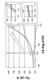
- FIG. 3 is a diagram showing a change in the in-cylinder gas temperature in the compression stroke, and an enlarged view is attached to the vicinity of the intake valve closing timing (IVC in the drawing) and the compression top dead center (TDC in the drawing).
- the “compression stroke” in the present embodiment means from the intake valve closing timing to the exhaust valve opening timing.
- T ⁇ V (k-1) constant (1)
- T is the in-cylinder gas temperature
- V is the combustion chamber volume
- k is the specific heat ratio
- Ttdc ⁇ Vtdc (k ⁇ 1) Tivc ⁇ Vivc (k ⁇ 1) (2)
- Equation (3) is obtained by transforming Equation (2).
- Ttdc Tivc ⁇ ⁇ (k ⁇ 1) (3) Where ⁇ is the compression ratio.
- the in-cylinder gas temperature at the compression top dead center is approximately twice the in-cylinder gas temperature at the intake valve closing timing.
- the temperature difference at the intake valve closing timing is doubled at the compression top dead center. That is, if the in-cylinder gas temperature is decreased at the intake valve closing timing, the temperature decrease amount at the compression top dead center is doubled.
- fuel injection control is performed such that the in-cylinder gas temperature at the intake valve closing timing is further lowered.
- FIG. 4 is an example of a timing chart when the in-cylinder gas temperature decreases due to the latent heat of vaporization of the fuel.
- the “wall” in the figure means the head side wall surface and the block side wall surface.
- the “evaporation amount”, “heat transfer amount from the wall”, and “temperature change amount due to latent heat” are amounts at each timing. Therefore, the area surrounded by each chart and the horizontal axis corresponds to the amount that affects the in-cylinder gas temperature.
- the injected fuel starts to evaporate from the timing T2 with a time delay.
- the amount of evaporation gradually increases as the amount of fuel in the cylinder increases and the diffusion of fuel proceeds. Thereafter, the amount of evaporation decreases as the amount of unevaporated fuel decreases and fuel injection stops.
- the amount of change in temperature due to latent heat of vaporization shows the same behavior as the above behavior of the amount of evaporation.
- the direction of temperature change is the direction in which the in-cylinder gas temperature is lowered. Thereby, the in-cylinder gas temperature starts to decrease.
- the amount of heat transferred from the wall also affects the in-cylinder gas temperature.
- the amount of heat transfer from the wall increases as the difference between the in-cylinder gas temperature and the wall temperature increases. That is, when the in-cylinder gas temperature decreases due to latent heat of vaporization, the amount of heat transfer from the wall increases with a delay time.
- the in-cylinder gas temperature that has decreased due to latent heat of vaporization then increases due to heat transfer from the wall.
- the controller 100 sets the start timing of the third fuel injection in FIG. 2 so that the timing T3 immediately before the in-cylinder gas temperature starts to rise coincides with the intake valve closing timing. That is, the second fuel injection and the third fuel injection of the three-stage injection are brought close to the intake valve closing timing, and in particular, the third fuel injection timing is set as described above. If the interval between the second fuel injection and the third fuel injection is made closer, the third fuel injection will be performed while the in-cylinder gas temperature is lowered by the second fuel injection. The in-cylinder gas temperature at the closing timing can be effectively reduced.
- the mode of fuel injection for reducing the in-cylinder gas temperature at the intake valve closing timing is not limited to the above.
- the fuel injection timing of single stage injection is set to the timing described above.
- the amount of heat transfer from the wall increases due to the longer period during which the fuel evaporates, so the amount of fuel injection per injection is greater than in multistage injection, so The margin for lowering the gas temperature increases.
- it may be switched to a single-stage injection in a high water temperature state.
- injection center of gravity the center of gravity of the multi-stage injection
- the injection center of gravity will be described with reference to FIG.
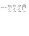
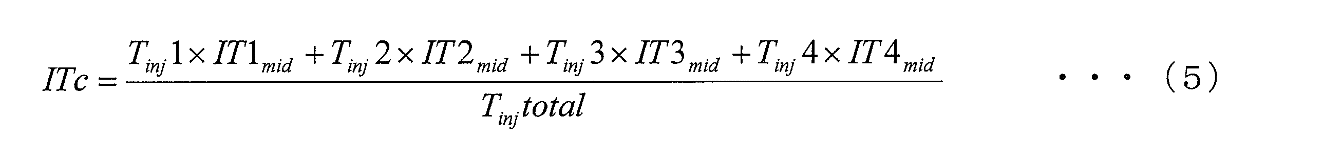
- FIG. 7 is a diagram showing fuel injection pulses of four-stage injection.
- IT1-IT4 is the start timing of each fuel injection, and T inj 1-T inj 4 is the fuel injection period (injection pulse width) of each fuel injection.
- IT1mid-IT4mid is the midpoint of each fuel injection period. At this time, the injection center of gravity ITc can be expressed by Expression (5).
- T inj total is a total value of each injection pulse width.
- the fuel injection timing is set so that the injection center of gravity ITc and the intake valve closing timing coincide with each other, the amount of fuel injection before the intake valve closing timing is reduced, so that the intake air is compared with the cases of FIGS.
- the effect of reducing the in-cylinder gas temperature at the valve closing timing is reduced.
- the in-cylinder gas temperature decreases due to the latent heat of vaporization of the fuel injected in the compression stroke.
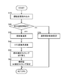
- FIG. 8 is a flowchart showing a control routine of the fuel injection control executed by the controller 100.
- step S10 the controller 100 reads the operating state. Specifically, the detection signal of the crank angle sensor 18 is read as the engine rotation speed, and the detection signal of the accelerator pedal opening sensor 17 is read as the load.
- step S20 the controller 100 determines whether or not it is in a high water temperature state. This determination is made based on the threshold value described above. When it is in a high water temperature state, the process of step S30 is performed, and when it is not a high water temperature state, the process of step S70 is performed. In step S70, the controller 100 executes normal fuel injection control, that is, fuel injection control for the cold state when the engine is cold, and for the warm state when the engine is warm.
- step S30 the controller 100 calculates the fuel injection amount.
- a known calculation method is used for calculating the fuel injection amount. That is, a fuel injection amount map having engine speed, load, and parameters is created in advance, and the map is searched using the engine speed and load read in step S10.
- step S40 the controller 100 calculates the conversion angle of the variable valve mechanism VTC.
- the variable valve mechanism VTC is a mechanism that can variably control the opening / closing timing of the intake valve. Since the variable valve mechanism VTC used in the present embodiment is the same as a known one, a description of the configuration of the variable valve mechanism VTC is omitted.
- the controller 100 creates in advance a conversion angle map using the load as the operating state and the engine speed as parameters, and searches the map using the read operating state. If the variable valve mechanism VTC is not provided, this step is omitted.
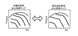
- step S50 the controller 100 switches the fuel injection timing to the timing according to the high water temperature state as described above.
- the injection time map for the cold state is switched to the injection timing map for the high water temperature state.
- Each injection timing map is obtained by assigning an injection timing suitable for each operation state, using the load as the operation state and the engine speed as parameters.
- an injection timing map for each injection is prepared. Then, the fuel injection start timing is calculated from the fuel injection timing map for the high water temperature state.
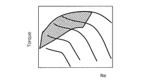
- the ignition timing for the high water temperature state may be calculated by calculation only in the operation region where knocking is likely to occur.
- the shaded area is an operation area where knocking is likely to occur.
- the fuel injection timing ITn for reducing the in-cylinder gas temperature at the intake valve closing timing can be calculated by the equation (6).
- IVC-Tevap IVC-Tevap (6)
- IVC is the intake valve closing timing
- Tevap is the time required from when the temperature starts to decrease due to latent heat of evaporation until the amount of temperature decrease becomes maximum.
- calculation of the ignition timing for preventing knocking is performed only in the operation region where knocking is likely to occur, and the calculation timing is reduced by using the ignition timing map for the cold state as it is in other operation regions. Can do.
- the ignition timing for the high water temperature state may be calculated only in the operation region where knocking is likely to occur.
- the injection center of gravity ITc is determined by equation (7). Based on the injection center of gravity ITc, the start timing of each fuel injection can be calculated.
- step S60 the controller 100 sets the fuel injection amount obtained in step S30 and the fuel injection start timing obtained in step S50 as the current fuel injection amount and the fuel injection start timing.
- the controller 100 as the fuel injection control device of the present embodiment is a spark ignition type that can independently control the circulation of the coolant in the head side cooling passage 21 and the circulation of the coolant in the block side cooling passage 22.
- the fuel injection of the direct injection internal combustion engine 1 is controlled.
- the controller 100 sets an in-cylinder cooling fuel injection timing that becomes an intake valve closing timing while the in-cylinder gas temperature is lowered due to the latent heat of vaporization of the injected fuel in a high water temperature state, and for in-cylinder cooling.
- Fuel injection is executed based on the fuel injection timing.
- knocking can be prevented by reducing the in-cylinder gas temperature in the vicinity of the compression top dead center where knocking is likely to occur. That is, it is possible to promote an increase in the oil temperature while preventing knocking.
- the controller 100 sets the in-cylinder cooling fuel injection timing so that the intake valve closing timing is reached when the amount of in-cylinder gas temperature decrease due to the latent heat of vaporization of the injected fuel is maximum.
- the in-cylinder gas temperature near the compression top dead center can be further reduced.
- the controller 100 sets one of the multi-stage injections to the in-cylinder cooling fuel injection timing.
- the in-cylinder gas temperature in the vicinity of the compression top dead center can be lowered using the latent heat of vaporization of the fuel injected by any of the injections.
- the controller 100 sets the last fuel injection of the plurality of fuel injections to the fuel injection timing for in-cylinder cooling. Therefore, compared with the case where fuel is injected during the compression stroke, the fuel mixing time can be increased, so that not only knocking can be prevented, but also exhaust emission deterioration can be prevented.
- the controller 100 switches to single-stage injection in the high water temperature state, and sets the fuel injection timing of single-stage injection to the fuel injection timing for in-cylinder cooling. Also good. Also in this case, knocking can be prevented by reducing the in-cylinder gas temperature near the compression top dead center by the latent heat of vaporization of the fuel.
- the fuel injection timing for in-cylinder cooling may be the fuel injection timing of each multi-stage injection set so that the center of injection coincides with the intake valve closing timing. Even in this case, knocking can be prevented by reducing the in-cylinder gas temperature in the vicinity of the compression top dead center by the latent heat of vaporization of the fuel.
- the circulation of the cooling water in the block-side cooling passage 22 may be stopped when the water temperature in the block-side cooling passage 22 becomes lower than 95 ° C., for example. This is because the friction between the piston and the cylinder wall is reduced by increasing the temperature of the cylinder block 3, and the reduction in fuel consumption performance is suppressed. In this case, knocking is likely to occur as the temperature of the cylinder block 3 rises. Therefore, the above-described fuel injection control in the high water temperature state is executed to prevent knocking.
Landscapes
- Engineering & Computer Science (AREA)
- Chemical & Material Sciences (AREA)
- Combustion & Propulsion (AREA)
- Mechanical Engineering (AREA)
- General Engineering & Computer Science (AREA)
- Computer Hardware Design (AREA)
- Microelectronics & Electronic Packaging (AREA)
- Electrical Control Of Air Or Fuel Supplied To Internal-Combustion Engine (AREA)
- Combined Controls Of Internal Combustion Engines (AREA)
- Fuel-Injection Apparatus (AREA)
- Cylinder Crankcases Of Internal Combustion Engines (AREA)
- Output Control And Ontrol Of Special Type Engine (AREA)
Abstract
Description
ただし、Tは筒内ガス温度、Vは燃焼室容積、kは比熱比である。
ただし、εは圧縮比である。
ただし、IVCは吸気バルブ閉タイミング、Tevapは蒸発潜熱によって温度が低下し始めてから、温度低下量が最大になるまでに要する時間、である。
Claims (10)
- シリンダヘッドを冷却するヘッド側冷却通路と、シリンダブロックを冷却するブロック側冷却通路と、を含み、前記ヘッド側冷却通路の冷却液の循環と前記ブロック側冷却通路の冷却液の循環とを独立して制御し得る冷却装置を備える火花点火式の筒内直噴内燃機関の燃料噴射を制御する燃料噴射制御装置において、
前記ヘッド側冷却通路に冷却液を循環させ、前記ブロック側冷却通路の冷却液の循環を停止した状態で、噴射した燃料の蒸発潜熱による筒内ガス温度低下が生じている間に吸気弁閉弁タイミングとなる筒内冷却用燃料噴射タイミングを設定する燃料噴射タイミング設定手段を備え、
前記筒内冷却用燃料噴射タイミングに基づいて燃料噴射を実行する燃料噴射制御装置。 - 請求項1に記載の燃料噴射制御装置において、
前記筒内冷却用燃料噴射タイミングは、噴射した燃料の蒸発潜熱による筒内ガス温度低下量が最大のときに吸気弁閉弁タイミングとなる燃料噴射タイミングである燃料噴射制御装置。 - 請求項1または2に記載の燃料噴射制御装置において、
1サイクル当たり複数回の燃料噴射を行う多段噴射の場合には、
前記燃料噴射タイミング設定手段は、前記複数回の燃料噴射のいずれかを前記筒内冷却用燃料噴射タイミングにする燃料噴射制御装置。 - 請求項3に記載の燃料噴射制御装置において、
前記燃料噴射タイミング設定手段は、前記複数回の燃料噴射の最後の燃料噴射を前記筒内冷却用燃料噴射タイミングにする燃料噴射制御装置。 - 請求項1または2に記載の燃料噴射制御装置において、
1サイクル当たり複数回の燃料噴射を行う多段噴射の場合であっても、1サイクル当たり1回の燃料噴射を行う単段噴射に切り換え、
前記燃料噴射タイミング設定手段は、1回の燃料噴射を前記筒内冷却用燃料噴射タイミングにする燃料噴射制御装置。 - 請求項1に記載の燃料噴射制御装置において、
1サイクル当たり複数回の燃料噴射を行う多段噴射の場合には、
前記筒内冷却用燃料噴射タイミングは、前記多段噴射の噴射重心が吸気弁閉タイミングと一致するように設定された、前記多段噴射の各回の燃料噴射タイミングである燃料噴射制御装置。 - 請求項1から6のいずれかに記載の燃料噴射制御装置において、
前記ヘッド側冷却通路の冷却水温を検知するヘッド側水温検知手段、または前記シリンダヘッドの壁温を検知するヘッド側壁温検知手段、の少なくとも一方をさらに備え、
前記ヘッド側冷却通路の冷却水温または前記シリンダヘッドの壁温が所定値以上の場合に、前記燃料噴射タイミング設定手段が前記筒内冷却用燃料噴射タイミングを設定する燃料噴射制御装置。 - 請求項1から7のいずれかに記載の燃料噴射制御装置において、
前記内燃機関の潤滑油の温度を検知する油温検知手段をさらに備え、
前記潤滑油の温度が所定値以下の場合に、前記燃料噴射タイミング設定手段が前記筒内冷却用燃料噴射タイミングを設定する燃料噴射制御装置。 - 請求項1に記載の燃料噴射制御装置において、
前記筒内冷却用燃料噴射タイミングは、吸気弁閉タイミングよりも燃料噴射期間分だけ進角側のタイミングである燃料噴射制御装置。 - シリンダヘッドを冷却するヘッド側冷却通路と、シリンダブロックを冷却するブロック側冷却通路と、を含み、前記ヘッド側冷却通路の冷却液の循環と前記ブロック側冷却通路の冷却液の循環とを独立して制御し得る冷却装置を備える火花点火式の筒内直噴内燃機関の燃料噴射を制御する燃料噴射制御方法において、
前記ヘッド側冷却通路に冷却液を循環させ、前記ブロック側冷却通路の冷却液の循環を停止した状態で、噴射した燃料の蒸発潜熱による筒内ガス温度低下が生じている間に吸気弁閉弁タイミングとなる筒内冷却用燃料噴射タイミングを設定し、
前記筒内冷却用燃料噴射タイミングに基づいて燃料噴射を実行する燃料噴射制御方法。
Priority Applications (8)
| Application Number | Priority Date | Filing Date | Title |
|---|---|---|---|
| MX2016014732A MX361832B (es) | 2014-05-15 | 2014-05-15 | Dispositivo de control de inyección de combustible y método de control de inyección de combustible para un motor de combustión interna. |
| RU2016149155A RU2657011C1 (ru) | 2014-05-15 | 2014-05-15 | Устройство управления впрыском топлива и способ управления впрыском топлива для двигателя внутреннего сгорания |
| EP14891693.5A EP3144513B1 (en) | 2014-05-15 | 2014-05-15 | Fuel injection control device and fuel injection control method for internal combustion engine |
| JP2016519059A JP6057021B2 (ja) | 2014-05-15 | 2014-05-15 | 内燃機関の燃料噴射制御装置及び燃料噴射制御方法 |
| CN201480078889.3A CN106460714B (zh) | 2014-05-15 | 2014-05-15 | 内燃机的燃料喷射控制装置以及燃料喷射控制方法 |
| US15/302,747 US10047693B2 (en) | 2014-05-15 | 2014-05-15 | Fuel injection control device and fuel injection control method for internal combustion engine |
| MYPI2016704138A MY191525A (en) | 2014-05-15 | 2014-05-15 | Fuel injection control device and fuel injection control method for an internal combustion engine |
| PCT/JP2014/063002 WO2015173937A1 (ja) | 2014-05-15 | 2014-05-15 | 内燃機関の燃料噴射制御装置及び燃料噴射制御方法 |
Applications Claiming Priority (1)
| Application Number | Priority Date | Filing Date | Title |
|---|---|---|---|
| PCT/JP2014/063002 WO2015173937A1 (ja) | 2014-05-15 | 2014-05-15 | 内燃機関の燃料噴射制御装置及び燃料噴射制御方法 |
Publications (1)
| Publication Number | Publication Date |
|---|---|
| WO2015173937A1 true WO2015173937A1 (ja) | 2015-11-19 |
Family
ID=54479506
Family Applications (1)
| Application Number | Title | Priority Date | Filing Date |
|---|---|---|---|
| PCT/JP2014/063002 Ceased WO2015173937A1 (ja) | 2014-05-15 | 2014-05-15 | 内燃機関の燃料噴射制御装置及び燃料噴射制御方法 |
Country Status (8)
| Country | Link |
|---|---|
| US (1) | US10047693B2 (ja) |
| EP (1) | EP3144513B1 (ja) |
| JP (1) | JP6057021B2 (ja) |
| CN (1) | CN106460714B (ja) |
| MX (1) | MX361832B (ja) |
| MY (1) | MY191525A (ja) |
| RU (1) | RU2657011C1 (ja) |
| WO (1) | WO2015173937A1 (ja) |
Cited By (2)
| Publication number | Priority date | Publication date | Assignee | Title |
|---|---|---|---|---|
| US20180347501A1 (en) * | 2015-11-28 | 2018-12-06 | Daimler Ag | Method for Operating an Internal Combustion Engine, in Particular of a Motor Vehicle |
| US20250341191A1 (en) * | 2022-05-23 | 2025-11-06 | Phinia Delphi Luxembourg Sarl | Method of operating a hydrogen internal combustion engine |
Families Citing this family (5)
| Publication number | Priority date | Publication date | Assignee | Title |
|---|---|---|---|---|
| JP2017078344A (ja) * | 2015-10-19 | 2017-04-27 | トヨタ自動車株式会社 | 内燃機関の制御装置 |
| US10273922B2 (en) * | 2016-02-12 | 2019-04-30 | Nissan Motor Co., Ltd. | Control method and control device of direct injection internal combustion engine |
| DE102016203436B4 (de) * | 2016-03-02 | 2017-11-30 | Continental Automotive Gmbh | Verfahren und Vorrichtung zum Ermitteln eines Einspritzzeitpunkts zum Einspritzen eines Kraftstoffs |
| JP6654594B2 (ja) * | 2017-03-16 | 2020-02-26 | ヤンマー株式会社 | エンジンシステム |
| WO2021011528A1 (en) | 2019-07-15 | 2021-01-21 | The Research Foundation For The State University Of New York | Method for control of advanced combustion through split direct injection of high heat of vaporization fuel or water fuel mixtures |
Citations (3)
| Publication number | Priority date | Publication date | Assignee | Title |
|---|---|---|---|---|
| JPH1113512A (ja) * | 1997-06-27 | 1999-01-19 | Nippon Soken Inc | 筒内直接噴射内燃機関 |
| JP2000054884A (ja) * | 1998-08-10 | 2000-02-22 | Toyota Central Res & Dev Lab Inc | 筒内噴射式内燃機関の燃料噴射制御方法 |
| JP2013053606A (ja) * | 2011-09-06 | 2013-03-21 | Mazda Motor Corp | リーンバーンエンジンの冷却装置 |
Family Cites Families (13)
| Publication number | Priority date | Publication date | Assignee | Title |
|---|---|---|---|---|
| JP2712711B2 (ja) * | 1990-02-16 | 1998-02-16 | 株式会社デンソー | 内燃機関の冷却方法及びその装置 |
| RU2007593C1 (ru) * | 1990-11-19 | 1994-02-15 | Сагаков Станислав Святославович | Способ работы двигателя внутреннего сгорания |
| DE10061546B4 (de) * | 2000-12-11 | 2011-07-21 | Behr Thermot-tronik GmbH, 70806 | Kühlanlage für einen mit flüssigem Kühlmittel gekühlten Verbrennungsmotor eines Kraftfahrzeuges |
| JP2003003843A (ja) * | 2001-04-20 | 2003-01-08 | Toyota Motor Corp | 蓄熱装置を備えた内燃機関 |
| US6912989B2 (en) * | 2003-04-30 | 2005-07-05 | Nissan Motor Co., Ltd. | Fuel injection control device for a direct fuel injection engine |
| JP4353216B2 (ja) * | 2006-08-04 | 2009-10-28 | トヨタ自動車株式会社 | 筒内噴射式火花点火内燃機関 |
| JP4379479B2 (ja) * | 2007-02-28 | 2009-12-09 | 株式会社日立製作所 | 筒内噴射式エンジンの制御方法、当該制御方法を実施するための制御装置、当該制御装置に用いられる制御回路装置 |
| US8165788B2 (en) * | 2009-05-22 | 2012-04-24 | Ford Global Technlogies, Llc | Fuel-based injection control |
| EP2405118A4 (en) * | 2009-10-26 | 2013-09-04 | Toyota Motor Co Ltd | CONTROL DEVICE FOR INTERNAL COMBUSTION ENGINE |
| RU2432474C2 (ru) * | 2010-01-11 | 2011-10-27 | Государственное образовательное учреждение высшего профессионального образования Самарский государственный технический университет | Способ работы поршневого двигателя внутреннего сгорания |
| US8447496B2 (en) * | 2010-09-17 | 2013-05-21 | Ford Global Technologies, Llc | Fuel-based injection control |
| JP4924751B1 (ja) * | 2010-11-09 | 2012-04-25 | マツダ株式会社 | 火花点火式直噴エンジンの制御方法及びその制御装置 |
| DE102012200746A1 (de) * | 2012-01-19 | 2013-07-25 | Ford Global Technologies, Llc | Brennkraftmaschine mit im Kühlmittelkreislauf angeordneter Pumpe und Verfahren zum Betreiben einer derartigen Brennkraftmaschine |
-
2014
- 2014-05-15 US US15/302,747 patent/US10047693B2/en not_active Expired - Fee Related
- 2014-05-15 CN CN201480078889.3A patent/CN106460714B/zh not_active Expired - Fee Related
- 2014-05-15 RU RU2016149155A patent/RU2657011C1/ru active
- 2014-05-15 EP EP14891693.5A patent/EP3144513B1/en active Active
- 2014-05-15 WO PCT/JP2014/063002 patent/WO2015173937A1/ja not_active Ceased
- 2014-05-15 MX MX2016014732A patent/MX361832B/es active IP Right Grant
- 2014-05-15 MY MYPI2016704138A patent/MY191525A/en unknown
- 2014-05-15 JP JP2016519059A patent/JP6057021B2/ja not_active Expired - Fee Related
Patent Citations (3)
| Publication number | Priority date | Publication date | Assignee | Title |
|---|---|---|---|---|
| JPH1113512A (ja) * | 1997-06-27 | 1999-01-19 | Nippon Soken Inc | 筒内直接噴射内燃機関 |
| JP2000054884A (ja) * | 1998-08-10 | 2000-02-22 | Toyota Central Res & Dev Lab Inc | 筒内噴射式内燃機関の燃料噴射制御方法 |
| JP2013053606A (ja) * | 2011-09-06 | 2013-03-21 | Mazda Motor Corp | リーンバーンエンジンの冷却装置 |
Non-Patent Citations (1)
| Title |
|---|
| See also references of EP3144513A4 * |
Cited By (2)
| Publication number | Priority date | Publication date | Assignee | Title |
|---|---|---|---|---|
| US20180347501A1 (en) * | 2015-11-28 | 2018-12-06 | Daimler Ag | Method for Operating an Internal Combustion Engine, in Particular of a Motor Vehicle |
| US20250341191A1 (en) * | 2022-05-23 | 2025-11-06 | Phinia Delphi Luxembourg Sarl | Method of operating a hydrogen internal combustion engine |
Also Published As
| Publication number | Publication date |
|---|---|
| EP3144513A1 (en) | 2017-03-22 |
| EP3144513B1 (en) | 2019-12-04 |
| MX361832B (es) | 2018-12-18 |
| JPWO2015173937A1 (ja) | 2017-04-20 |
| CN106460714B (zh) | 2019-12-31 |
| US10047693B2 (en) | 2018-08-14 |
| EP3144513A4 (en) | 2017-05-03 |
| CN106460714A (zh) | 2017-02-22 |
| JP6057021B2 (ja) | 2017-01-11 |
| US20170030286A1 (en) | 2017-02-02 |
| RU2657011C1 (ru) | 2018-06-08 |
| MY191525A (en) | 2022-06-29 |
| MX2016014732A (es) | 2017-03-06 |
Similar Documents
| Publication | Publication Date | Title |
|---|---|---|
| JP6057021B2 (ja) | 内燃機関の燃料噴射制御装置及び燃料噴射制御方法 | |
| US8746187B2 (en) | Engine cooling device | |
| US20100108031A1 (en) | Engine and exhaust heating | |
| RU2689130C1 (ru) | Система двигателя внутреннего сгорания и способ управления для двигателя внутреннего сгорания | |
| JP5282827B2 (ja) | エンジンの冷却装置 | |
| RU2607098C1 (ru) | УСТРОЙСТВО УПРАВЛЕНИЯ ДЛЯ ДВИГАТЕЛЯ ВНУТРЕННЕГО СГОРАНИЯ (варианты) | |
| RU2638251C1 (ru) | Устройство охлаждения для двигателя внутреннего сгорания | |
| JP2014152615A (ja) | 可変気筒エンジン | |
| US20130247848A1 (en) | Engine cooling apparatus | |
| JP2017180110A (ja) | 内燃機関 | |
| JP2012117389A (ja) | エンジンの冷却制御装置 | |
| RU2638228C2 (ru) | Управляющее устройство для двигателя внутреннего сгорания | |
| US9228464B2 (en) | Method and device for controlling an internal combustion engine | |
| JP2013057254A (ja) | 火花点火式直噴エンジン | |
| JP2020026751A (ja) | 内燃機関の制御装置 | |
| JP2012072668A (ja) | 内燃機関システム | |
| JP5051306B2 (ja) | エンジンの冷却装置 | |
| JP2006257902A (ja) | 内燃機関の冷却装置 | |
| JP5664483B2 (ja) | 内燃機関の燃料噴射制御装置 | |
| JP5577788B2 (ja) | エンジンの冷却装置 | |
| JP2022028512A (ja) | 内燃機関の制御装置 | |
| JP2015055220A (ja) | 内燃機関の制御装置 | |
| JP2011094537A (ja) | エンジンの冷却装置 | |
| JP5358312B2 (ja) | 冷却装置 | |
| JP2010255512A (ja) | エンジン制御装置 |
Legal Events
| Date | Code | Title | Description |
|---|---|---|---|
| 121 | Ep: the epo has been informed by wipo that ep was designated in this application |
Ref document number: 14891693 Country of ref document: EP Kind code of ref document: A1 |
|
| ENP | Entry into the national phase |
Ref document number: 2016519059 Country of ref document: JP Kind code of ref document: A |
|
| WWE | Wipo information: entry into national phase |
Ref document number: 15302747 Country of ref document: US |
|
| WWE | Wipo information: entry into national phase |
Ref document number: MX/A/2016/014732 Country of ref document: MX |
|
| NENP | Non-entry into the national phase |
Ref country code: DE |
|
| WWE | Wipo information: entry into national phase |
Ref document number: IDP00201607813 Country of ref document: ID |
|
| REG | Reference to national code |
Ref country code: BR Ref legal event code: B01A Ref document number: 112016026115 Country of ref document: BR |
|
| REEP | Request for entry into the european phase |
Ref document number: 2014891693 Country of ref document: EP |
|
| WWE | Wipo information: entry into national phase |
Ref document number: 2014891693 Country of ref document: EP |
|
| ENP | Entry into the national phase |
Ref document number: 2016149155 Country of ref document: RU Kind code of ref document: A |
|
| ENP | Entry into the national phase |
Ref document number: 112016026115 Country of ref document: BR Kind code of ref document: A2 Effective date: 20161108 |