WO2015174255A1 - 成形品の製造方法、成形品の製造装置 - Google Patents
成形品の製造方法、成形品の製造装置 Download PDFInfo
- Publication number
- WO2015174255A1 WO2015174255A1 PCT/JP2015/062611 JP2015062611W WO2015174255A1 WO 2015174255 A1 WO2015174255 A1 WO 2015174255A1 JP 2015062611 W JP2015062611 W JP 2015062611W WO 2015174255 A1 WO2015174255 A1 WO 2015174255A1
- Authority
- WO
- WIPO (PCT)
- Prior art keywords
- liquid
- gas
- heating cylinder
- injection
- mold
- Prior art date
- Legal status (The legal status is an assumption and is not a legal conclusion. Google has not performed a legal analysis and makes no representation as to the accuracy of the status listed.)
- Ceased
Links
Images


Classifications
-
- B—PERFORMING OPERATIONS; TRANSPORTING
- B29—WORKING OF PLASTICS; WORKING OF SUBSTANCES IN A PLASTIC STATE IN GENERAL
- B29B—PREPARATION OR PRETREATMENT OF THE MATERIAL TO BE SHAPED; MAKING GRANULES OR PREFORMS; RECOVERY OF PLASTICS OR OTHER CONSTITUENTS OF WASTE MATERIAL CONTAINING PLASTICS
- B29B7/00—Mixing; Kneading
- B29B7/80—Component parts, details or accessories; Auxiliary operations
- B29B7/88—Adding charges, i.e. additives
- B29B7/94—Liquid charges
-
- B—PERFORMING OPERATIONS; TRANSPORTING
- B29—WORKING OF PLASTICS; WORKING OF SUBSTANCES IN A PLASTIC STATE IN GENERAL
- B29B—PREPARATION OR PRETREATMENT OF THE MATERIAL TO BE SHAPED; MAKING GRANULES OR PREFORMS; RECOVERY OF PLASTICS OR OTHER CONSTITUENTS OF WASTE MATERIAL CONTAINING PLASTICS
- B29B13/00—Conditioning or physical treatment of the material to be shaped
- B29B13/02—Conditioning or physical treatment of the material to be shaped by heating
-
- B—PERFORMING OPERATIONS; TRANSPORTING
- B29—WORKING OF PLASTICS; WORKING OF SUBSTANCES IN A PLASTIC STATE IN GENERAL
- B29B—PREPARATION OR PRETREATMENT OF THE MATERIAL TO BE SHAPED; MAKING GRANULES OR PREFORMS; RECOVERY OF PLASTICS OR OTHER CONSTITUENTS OF WASTE MATERIAL CONTAINING PLASTICS
- B29B7/00—Mixing; Kneading
- B29B7/30—Mixing; Kneading continuous, with mechanical mixing or kneading devices
- B29B7/58—Component parts, details or accessories; Auxiliary operations
- B29B7/72—Measuring, controlling or regulating
-
- B—PERFORMING OPERATIONS; TRANSPORTING
- B29—WORKING OF PLASTICS; WORKING OF SUBSTANCES IN A PLASTIC STATE IN GENERAL
- B29B—PREPARATION OR PRETREATMENT OF THE MATERIAL TO BE SHAPED; MAKING GRANULES OR PREFORMS; RECOVERY OF PLASTICS OR OTHER CONSTITUENTS OF WASTE MATERIAL CONTAINING PLASTICS
- B29B7/00—Mixing; Kneading
- B29B7/74—Mixing; Kneading using other mixers or combinations of mixers, e.g. of dissimilar mixers ; Plant
- B29B7/7404—Mixing devices specially adapted for foamable substances
-
- B—PERFORMING OPERATIONS; TRANSPORTING
- B29—WORKING OF PLASTICS; WORKING OF SUBSTANCES IN A PLASTIC STATE IN GENERAL
- B29B—PREPARATION OR PRETREATMENT OF THE MATERIAL TO BE SHAPED; MAKING GRANULES OR PREFORMS; RECOVERY OF PLASTICS OR OTHER CONSTITUENTS OF WASTE MATERIAL CONTAINING PLASTICS
- B29B7/00—Mixing; Kneading
- B29B7/80—Component parts, details or accessories; Auxiliary operations
- B29B7/82—Heating or cooling
- B29B7/823—Temperature control
-
- B—PERFORMING OPERATIONS; TRANSPORTING
- B29—WORKING OF PLASTICS; WORKING OF SUBSTANCES IN A PLASTIC STATE IN GENERAL
- B29B—PREPARATION OR PRETREATMENT OF THE MATERIAL TO BE SHAPED; MAKING GRANULES OR PREFORMS; RECOVERY OF PLASTICS OR OTHER CONSTITUENTS OF WASTE MATERIAL CONTAINING PLASTICS
- B29B7/00—Mixing; Kneading
- B29B7/80—Component parts, details or accessories; Auxiliary operations
- B29B7/82—Heating or cooling
- B29B7/826—Apparatus therefor
-
- B—PERFORMING OPERATIONS; TRANSPORTING
- B29—WORKING OF PLASTICS; WORKING OF SUBSTANCES IN A PLASTIC STATE IN GENERAL
- B29B—PREPARATION OR PRETREATMENT OF THE MATERIAL TO BE SHAPED; MAKING GRANULES OR PREFORMS; RECOVERY OF PLASTICS OR OTHER CONSTITUENTS OF WASTE MATERIAL CONTAINING PLASTICS
- B29B7/00—Mixing; Kneading
- B29B7/80—Component parts, details or accessories; Auxiliary operations
- B29B7/88—Adding charges, i.e. additives
-
- B—PERFORMING OPERATIONS; TRANSPORTING
- B29—WORKING OF PLASTICS; WORKING OF SUBSTANCES IN A PLASTIC STATE IN GENERAL
- B29C—SHAPING OR JOINING OF PLASTICS; SHAPING OF MATERIAL IN A PLASTIC STATE, NOT OTHERWISE PROVIDED FOR; AFTER-TREATMENT OF THE SHAPED PRODUCTS, e.g. REPAIRING
- B29C39/00—Shaping by casting, i.e. introducing the moulding material into a mould or between confining surfaces without significant moulding pressure; Apparatus therefor
- B29C39/003—Shaping by casting, i.e. introducing the moulding material into a mould or between confining surfaces without significant moulding pressure; Apparatus therefor characterised by the choice of material
-
- B—PERFORMING OPERATIONS; TRANSPORTING
- B29—WORKING OF PLASTICS; WORKING OF SUBSTANCES IN A PLASTIC STATE IN GENERAL
- B29C—SHAPING OR JOINING OF PLASTICS; SHAPING OF MATERIAL IN A PLASTIC STATE, NOT OTHERWISE PROVIDED FOR; AFTER-TREATMENT OF THE SHAPED PRODUCTS, e.g. REPAIRING
- B29C39/00—Shaping by casting, i.e. introducing the moulding material into a mould or between confining surfaces without significant moulding pressure; Apparatus therefor
- B29C39/22—Component parts, details or accessories; Auxiliary operations
- B29C39/24—Feeding the material into the mould
-
- B—PERFORMING OPERATIONS; TRANSPORTING
- B29—WORKING OF PLASTICS; WORKING OF SUBSTANCES IN A PLASTIC STATE IN GENERAL
- B29C—SHAPING OR JOINING OF PLASTICS; SHAPING OF MATERIAL IN A PLASTIC STATE, NOT OTHERWISE PROVIDED FOR; AFTER-TREATMENT OF THE SHAPED PRODUCTS, e.g. REPAIRING
- B29C44/00—Shaping by internal pressure generated in the material, e.g. swelling or foaming ; Producing porous or cellular expanded plastics articles
- B29C44/34—Auxiliary operations
- B29C44/3442—Mixing, kneading or conveying the foamable material
- B29C44/3446—Feeding the blowing agent
-
- B—PERFORMING OPERATIONS; TRANSPORTING
- B29—WORKING OF PLASTICS; WORKING OF SUBSTANCES IN A PLASTIC STATE IN GENERAL
- B29C—SHAPING OR JOINING OF PLASTICS; SHAPING OF MATERIAL IN A PLASTIC STATE, NOT OTHERWISE PROVIDED FOR; AFTER-TREATMENT OF THE SHAPED PRODUCTS, e.g. REPAIRING
- B29C45/00—Injection moulding, i.e. forcing the required volume of moulding material through a nozzle into a closed mould; Apparatus therefor
- B29C45/0001—Injection moulding, i.e. forcing the required volume of moulding material through a nozzle into a closed mould; Apparatus therefor characterised by the choice of material
-
- B—PERFORMING OPERATIONS; TRANSPORTING
- B29—WORKING OF PLASTICS; WORKING OF SUBSTANCES IN A PLASTIC STATE IN GENERAL
- B29C—SHAPING OR JOINING OF PLASTICS; SHAPING OF MATERIAL IN A PLASTIC STATE, NOT OTHERWISE PROVIDED FOR; AFTER-TREATMENT OF THE SHAPED PRODUCTS, e.g. REPAIRING
- B29C45/00—Injection moulding, i.e. forcing the required volume of moulding material through a nozzle into a closed mould; Apparatus therefor
- B29C45/17—Component parts, details or accessories; Auxiliary operations
- B29C45/1703—Introducing an auxiliary fluid into the mould
- B29C45/174—Applying a pressurised fluid to the outer surface of the injected material inside the mould cavity, e.g. for preventing shrinkage marks
-
- B—PERFORMING OPERATIONS; TRANSPORTING
- B29—WORKING OF PLASTICS; WORKING OF SUBSTANCES IN A PLASTIC STATE IN GENERAL
- B29C—SHAPING OR JOINING OF PLASTICS; SHAPING OF MATERIAL IN A PLASTIC STATE, NOT OTHERWISE PROVIDED FOR; AFTER-TREATMENT OF THE SHAPED PRODUCTS, e.g. REPAIRING
- B29C45/00—Injection moulding, i.e. forcing the required volume of moulding material through a nozzle into a closed mould; Apparatus therefor
- B29C45/17—Component parts, details or accessories; Auxiliary operations
- B29C45/18—Feeding the material into the injection moulding apparatus, i.e. feeding the non-plastified material into the injection unit
- B29C45/1816—Feeding auxiliary material, e.g. colouring material
-
- B—PERFORMING OPERATIONS; TRANSPORTING
- B29—WORKING OF PLASTICS; WORKING OF SUBSTANCES IN A PLASTIC STATE IN GENERAL
- B29C—SHAPING OR JOINING OF PLASTICS; SHAPING OF MATERIAL IN A PLASTIC STATE, NOT OTHERWISE PROVIDED FOR; AFTER-TREATMENT OF THE SHAPED PRODUCTS, e.g. REPAIRING
- B29C45/00—Injection moulding, i.e. forcing the required volume of moulding material through a nozzle into a closed mould; Apparatus therefor
- B29C45/17—Component parts, details or accessories; Auxiliary operations
- B29C45/26—Moulds
- B29C45/34—Moulds having venting means
-
- B—PERFORMING OPERATIONS; TRANSPORTING
- B29—WORKING OF PLASTICS; WORKING OF SUBSTANCES IN A PLASTIC STATE IN GENERAL
- B29C—SHAPING OR JOINING OF PLASTICS; SHAPING OF MATERIAL IN A PLASTIC STATE, NOT OTHERWISE PROVIDED FOR; AFTER-TREATMENT OF THE SHAPED PRODUCTS, e.g. REPAIRING
- B29C48/00—Extrusion moulding, i.e. expressing the moulding material through a die or nozzle which imparts the desired form; Apparatus therefor
- B29C48/001—Combinations of extrusion moulding with other shaping operations
- B29C48/0012—Combinations of extrusion moulding with other shaping operations combined with shaping by internal pressure generated in the material, e.g. foaming
-
- B—PERFORMING OPERATIONS; TRANSPORTING
- B29—WORKING OF PLASTICS; WORKING OF SUBSTANCES IN A PLASTIC STATE IN GENERAL
- B29C—SHAPING OR JOINING OF PLASTICS; SHAPING OF MATERIAL IN A PLASTIC STATE, NOT OTHERWISE PROVIDED FOR; AFTER-TREATMENT OF THE SHAPED PRODUCTS, e.g. REPAIRING
- B29C48/00—Extrusion moulding, i.e. expressing the moulding material through a die or nozzle which imparts the desired form; Apparatus therefor
- B29C48/022—Extrusion moulding, i.e. expressing the moulding material through a die or nozzle which imparts the desired form; Apparatus therefor characterised by the choice of material
-
- B—PERFORMING OPERATIONS; TRANSPORTING
- B29—WORKING OF PLASTICS; WORKING OF SUBSTANCES IN A PLASTIC STATE IN GENERAL
- B29C—SHAPING OR JOINING OF PLASTICS; SHAPING OF MATERIAL IN A PLASTIC STATE, NOT OTHERWISE PROVIDED FOR; AFTER-TREATMENT OF THE SHAPED PRODUCTS, e.g. REPAIRING
- B29C48/00—Extrusion moulding, i.e. expressing the moulding material through a die or nozzle which imparts the desired form; Apparatus therefor
- B29C48/25—Component parts, details or accessories; Auxiliary operations
- B29C48/285—Feeding the extrusion material to the extruder
- B29C48/29—Feeding the extrusion material to the extruder in liquid form
-
- B—PERFORMING OPERATIONS; TRANSPORTING
- B29—WORKING OF PLASTICS; WORKING OF SUBSTANCES IN A PLASTIC STATE IN GENERAL
- B29B—PREPARATION OR PRETREATMENT OF THE MATERIAL TO BE SHAPED; MAKING GRANULES OR PREFORMS; RECOVERY OF PLASTICS OR OTHER CONSTITUENTS OF WASTE MATERIAL CONTAINING PLASTICS
- B29B7/00—Mixing; Kneading
- B29B7/80—Component parts, details or accessories; Auxiliary operations
- B29B7/82—Heating or cooling
-
- B—PERFORMING OPERATIONS; TRANSPORTING
- B29—WORKING OF PLASTICS; WORKING OF SUBSTANCES IN A PLASTIC STATE IN GENERAL
- B29C—SHAPING OR JOINING OF PLASTICS; SHAPING OF MATERIAL IN A PLASTIC STATE, NOT OTHERWISE PROVIDED FOR; AFTER-TREATMENT OF THE SHAPED PRODUCTS, e.g. REPAIRING
- B29C45/00—Injection moulding, i.e. forcing the required volume of moulding material through a nozzle into a closed mould; Apparatus therefor
- B29C45/17—Component parts, details or accessories; Auxiliary operations
- B29C45/1703—Introducing an auxiliary fluid into the mould
- B29C45/1704—Introducing an auxiliary fluid into the mould the fluid being introduced into the interior of the injected material which is still in a molten state, e.g. for producing hollow articles
- B29C2045/1722—Introducing an auxiliary fluid into the mould the fluid being introduced into the interior of the injected material which is still in a molten state, e.g. for producing hollow articles injecting fluids containing plastic material
-
- B—PERFORMING OPERATIONS; TRANSPORTING
- B29—WORKING OF PLASTICS; WORKING OF SUBSTANCES IN A PLASTIC STATE IN GENERAL
- B29C—SHAPING OR JOINING OF PLASTICS; SHAPING OF MATERIAL IN A PLASTIC STATE, NOT OTHERWISE PROVIDED FOR; AFTER-TREATMENT OF THE SHAPED PRODUCTS, e.g. REPAIRING
- B29C44/00—Shaping by internal pressure generated in the material, e.g. swelling or foaming ; Producing porous or cellular expanded plastics articles
- B29C44/34—Auxiliary operations
- B29C44/36—Feeding the material to be shaped
- B29C44/38—Feeding the material to be shaped into a closed space, i.e. to make articles of definite length
- B29C44/40—Feeding the material to be shaped into a closed space, i.e. to make articles of definite length by gravity, e.g. by casting
-
- B—PERFORMING OPERATIONS; TRANSPORTING
- B29—WORKING OF PLASTICS; WORKING OF SUBSTANCES IN A PLASTIC STATE IN GENERAL
- B29C—SHAPING OR JOINING OF PLASTICS; SHAPING OF MATERIAL IN A PLASTIC STATE, NOT OTHERWISE PROVIDED FOR; AFTER-TREATMENT OF THE SHAPED PRODUCTS, e.g. REPAIRING
- B29C44/00—Shaping by internal pressure generated in the material, e.g. swelling or foaming ; Producing porous or cellular expanded plastics articles
- B29C44/34—Auxiliary operations
- B29C44/36—Feeding the material to be shaped
- B29C44/38—Feeding the material to be shaped into a closed space, i.e. to make articles of definite length
- B29C44/42—Feeding the material to be shaped into a closed space, i.e. to make articles of definite length using pressure difference, e.g. by injection or by vacuum
-
- B—PERFORMING OPERATIONS; TRANSPORTING
- B29—WORKING OF PLASTICS; WORKING OF SUBSTANCES IN A PLASTIC STATE IN GENERAL
- B29C—SHAPING OR JOINING OF PLASTICS; SHAPING OF MATERIAL IN A PLASTIC STATE, NOT OTHERWISE PROVIDED FOR; AFTER-TREATMENT OF THE SHAPED PRODUCTS, e.g. REPAIRING
- B29C44/00—Shaping by internal pressure generated in the material, e.g. swelling or foaming ; Producing porous or cellular expanded plastics articles
- B29C44/34—Auxiliary operations
- B29C44/36—Feeding the material to be shaped
- B29C44/46—Feeding the material to be shaped into an open space or onto moving surfaces, i.e. to make articles of indefinite length
- B29C44/50—Feeding the material to be shaped into an open space or onto moving surfaces, i.e. to make articles of indefinite length using pressure difference, e.g. by extrusion or by spraying
-
- B—PERFORMING OPERATIONS; TRANSPORTING
- B29—WORKING OF PLASTICS; WORKING OF SUBSTANCES IN A PLASTIC STATE IN GENERAL
- B29K—INDEXING SCHEME ASSOCIATED WITH SUBCLASSES B29B, B29C OR B29D, RELATING TO MOULDING MATERIALS OR TO MATERIALS FOR MOULDS, REINFORCEMENTS, FILLERS OR PREFORMED PARTS, e.g. INSERTS
- B29K2009/00—Use of rubber derived from conjugated dienes, as moulding material
- B29K2009/06—SB polymers, i.e. butadiene-styrene polymers
-
- B—PERFORMING OPERATIONS; TRANSPORTING
- B29—WORKING OF PLASTICS; WORKING OF SUBSTANCES IN A PLASTIC STATE IN GENERAL
- B29K—INDEXING SCHEME ASSOCIATED WITH SUBCLASSES B29B, B29C OR B29D, RELATING TO MOULDING MATERIALS OR TO MATERIALS FOR MOULDS, REINFORCEMENTS, FILLERS OR PREFORMED PARTS, e.g. INSERTS
- B29K2023/00—Use of polyalkenes or derivatives thereof as moulding material
- B29K2023/04—Polymers of ethylene
- B29K2023/06—PE, i.e. polyethylene
-
- B—PERFORMING OPERATIONS; TRANSPORTING
- B29—WORKING OF PLASTICS; WORKING OF SUBSTANCES IN A PLASTIC STATE IN GENERAL
- B29K—INDEXING SCHEME ASSOCIATED WITH SUBCLASSES B29B, B29C OR B29D, RELATING TO MOULDING MATERIALS OR TO MATERIALS FOR MOULDS, REINFORCEMENTS, FILLERS OR PREFORMED PARTS, e.g. INSERTS
- B29K2023/00—Use of polyalkenes or derivatives thereof as moulding material
- B29K2023/10—Polymers of propylene
- B29K2023/12—PP, i.e. polypropylene
-
- B—PERFORMING OPERATIONS; TRANSPORTING
- B29—WORKING OF PLASTICS; WORKING OF SUBSTANCES IN A PLASTIC STATE IN GENERAL
- B29K—INDEXING SCHEME ASSOCIATED WITH SUBCLASSES B29B, B29C OR B29D, RELATING TO MOULDING MATERIALS OR TO MATERIALS FOR MOULDS, REINFORCEMENTS, FILLERS OR PREFORMED PARTS, e.g. INSERTS
- B29K2025/00—Use of polymers of vinyl-aromatic compounds or derivatives thereof as moulding material
- B29K2025/04—Polymers of styrene
- B29K2025/06—PS, i.e. polystyrene
-
- B—PERFORMING OPERATIONS; TRANSPORTING
- B29—WORKING OF PLASTICS; WORKING OF SUBSTANCES IN A PLASTIC STATE IN GENERAL
- B29K—INDEXING SCHEME ASSOCIATED WITH SUBCLASSES B29B, B29C OR B29D, RELATING TO MOULDING MATERIALS OR TO MATERIALS FOR MOULDS, REINFORCEMENTS, FILLERS OR PREFORMED PARTS, e.g. INSERTS
- B29K2027/00—Use of polyvinylhalogenides or derivatives thereof as moulding material
- B29K2027/06—PVC, i.e. polyvinylchloride
-
- B—PERFORMING OPERATIONS; TRANSPORTING
- B29—WORKING OF PLASTICS; WORKING OF SUBSTANCES IN A PLASTIC STATE IN GENERAL
- B29K—INDEXING SCHEME ASSOCIATED WITH SUBCLASSES B29B, B29C OR B29D, RELATING TO MOULDING MATERIALS OR TO MATERIALS FOR MOULDS, REINFORCEMENTS, FILLERS OR PREFORMED PARTS, e.g. INSERTS
- B29K2033/00—Use of polymers of unsaturated acids or derivatives thereof as moulding material
- B29K2033/04—Polymers of esters
- B29K2033/12—Polymers of methacrylic acid esters, e.g. PMMA, i.e. polymethylmethacrylate
-
- B—PERFORMING OPERATIONS; TRANSPORTING
- B29—WORKING OF PLASTICS; WORKING OF SUBSTANCES IN A PLASTIC STATE IN GENERAL
- B29K—INDEXING SCHEME ASSOCIATED WITH SUBCLASSES B29B, B29C OR B29D, RELATING TO MOULDING MATERIALS OR TO MATERIALS FOR MOULDS, REINFORCEMENTS, FILLERS OR PREFORMED PARTS, e.g. INSERTS
- B29K2067/00—Use of polyesters or derivatives thereof, as moulding material
- B29K2067/003—PET, i.e. poylethylene terephthalate
-
- B—PERFORMING OPERATIONS; TRANSPORTING
- B29—WORKING OF PLASTICS; WORKING OF SUBSTANCES IN A PLASTIC STATE IN GENERAL
- B29K—INDEXING SCHEME ASSOCIATED WITH SUBCLASSES B29B, B29C OR B29D, RELATING TO MOULDING MATERIALS OR TO MATERIALS FOR MOULDS, REINFORCEMENTS, FILLERS OR PREFORMED PARTS, e.g. INSERTS
- B29K2067/00—Use of polyesters or derivatives thereof, as moulding material
- B29K2067/006—PBT, i.e. polybutylene terephthalate
-
- B—PERFORMING OPERATIONS; TRANSPORTING
- B29—WORKING OF PLASTICS; WORKING OF SUBSTANCES IN A PLASTIC STATE IN GENERAL
- B29K—INDEXING SCHEME ASSOCIATED WITH SUBCLASSES B29B, B29C OR B29D, RELATING TO MOULDING MATERIALS OR TO MATERIALS FOR MOULDS, REINFORCEMENTS, FILLERS OR PREFORMED PARTS, e.g. INSERTS
- B29K2077/00—Use of PA, i.e. polyamides, e.g. polyesteramides or derivatives thereof, as moulding material
-
- B—PERFORMING OPERATIONS; TRANSPORTING
- B29—WORKING OF PLASTICS; WORKING OF SUBSTANCES IN A PLASTIC STATE IN GENERAL
- B29K—INDEXING SCHEME ASSOCIATED WITH SUBCLASSES B29B, B29C OR B29D, RELATING TO MOULDING MATERIALS OR TO MATERIALS FOR MOULDS, REINFORCEMENTS, FILLERS OR PREFORMED PARTS, e.g. INSERTS
- B29K2101/00—Use of unspecified macromolecular compounds as moulding material
- B29K2101/10—Thermosetting resins
-
- B—PERFORMING OPERATIONS; TRANSPORTING
- B29—WORKING OF PLASTICS; WORKING OF SUBSTANCES IN A PLASTIC STATE IN GENERAL
- B29K—INDEXING SCHEME ASSOCIATED WITH SUBCLASSES B29B, B29C OR B29D, RELATING TO MOULDING MATERIALS OR TO MATERIALS FOR MOULDS, REINFORCEMENTS, FILLERS OR PREFORMED PARTS, e.g. INSERTS
- B29K2105/00—Condition, form or state of moulded material or of the material to be shaped
- B29K2105/0005—Condition, form or state of moulded material or of the material to be shaped containing compounding ingredients
-
- B—PERFORMING OPERATIONS; TRANSPORTING
- B29—WORKING OF PLASTICS; WORKING OF SUBSTANCES IN A PLASTIC STATE IN GENERAL
- B29K—INDEXING SCHEME ASSOCIATED WITH SUBCLASSES B29B, B29C OR B29D, RELATING TO MOULDING MATERIALS OR TO MATERIALS FOR MOULDS, REINFORCEMENTS, FILLERS OR PREFORMED PARTS, e.g. INSERTS
- B29K2105/00—Condition, form or state of moulded material or of the material to be shaped
- B29K2105/0058—Liquid or visquous
- B29K2105/0067—Melt
-
- B—PERFORMING OPERATIONS; TRANSPORTING
- B29—WORKING OF PLASTICS; WORKING OF SUBSTANCES IN A PLASTIC STATE IN GENERAL
- B29K—INDEXING SCHEME ASSOCIATED WITH SUBCLASSES B29B, B29C OR B29D, RELATING TO MOULDING MATERIALS OR TO MATERIALS FOR MOULDS, REINFORCEMENTS, FILLERS OR PREFORMED PARTS, e.g. INSERTS
- B29K2105/00—Condition, form or state of moulded material or of the material to be shaped
- B29K2105/0088—Blends of polymers
-
- B—PERFORMING OPERATIONS; TRANSPORTING
- B29—WORKING OF PLASTICS; WORKING OF SUBSTANCES IN A PLASTIC STATE IN GENERAL
- B29K—INDEXING SCHEME ASSOCIATED WITH SUBCLASSES B29B, B29C OR B29D, RELATING TO MOULDING MATERIALS OR TO MATERIALS FOR MOULDS, REINFORCEMENTS, FILLERS OR PREFORMED PARTS, e.g. INSERTS
- B29K2105/00—Condition, form or state of moulded material or of the material to be shaped
- B29K2105/04—Condition, form or state of moulded material or of the material to be shaped cellular or porous
- B29K2105/041—Microporous
-
- B—PERFORMING OPERATIONS; TRANSPORTING
- B29—WORKING OF PLASTICS; WORKING OF SUBSTANCES IN A PLASTIC STATE IN GENERAL
- B29K—INDEXING SCHEME ASSOCIATED WITH SUBCLASSES B29B, B29C OR B29D, RELATING TO MOULDING MATERIALS OR TO MATERIALS FOR MOULDS, REINFORCEMENTS, FILLERS OR PREFORMED PARTS, e.g. INSERTS
- B29K2105/00—Condition, form or state of moulded material or of the material to be shaped
- B29K2105/26—Scrap or recycled material
-
- B—PERFORMING OPERATIONS; TRANSPORTING
- B29—WORKING OF PLASTICS; WORKING OF SUBSTANCES IN A PLASTIC STATE IN GENERAL
- B29L—INDEXING SCHEME ASSOCIATED WITH SUBCLASS B29C, RELATING TO PARTICULAR ARTICLES
- B29L2031/00—Other particular articles
- B29L2031/30—Vehicles, e.g. ships or aircraft, or body parts thereof
-
- B—PERFORMING OPERATIONS; TRANSPORTING
- B29—WORKING OF PLASTICS; WORKING OF SUBSTANCES IN A PLASTIC STATE IN GENERAL
- B29L—INDEXING SCHEME ASSOCIATED WITH SUBCLASS B29C, RELATING TO PARTICULAR ARTICLES
- B29L2031/00—Other particular articles
- B29L2031/34—Electrical apparatus, e.g. sparking plugs or parts thereof
-
- B—PERFORMING OPERATIONS; TRANSPORTING
- B29—WORKING OF PLASTICS; WORKING OF SUBSTANCES IN A PLASTIC STATE IN GENERAL
- B29L—INDEXING SCHEME ASSOCIATED WITH SUBCLASS B29C, RELATING TO PARTICULAR ARTICLES
- B29L2031/00—Other particular articles
- B29L2031/44—Furniture or parts thereof
Definitions
- the present invention relates to a method for manufacturing a molded product and a manufacturing apparatus.
- Patent Document 1 discloses a foaming method in which a molding material composed of a resin and a foaming agent is short shot while leaving an unfilled portion in a mold in which an insert is disposed, and the unfilled portion is filled with an expansion force due to foaming of the foaming agent.
- the resin is composed of a base material resin and a low molecular weight resin that is the same type as the base material resin and has a lower molecular weight than the base material resin.
- An object of the present invention is to stabilize the quality of a foam molded product.
- the method for producing a molded product according to claim 1 includes a step of injecting a predetermined amount of liquid into the molten resin, the vaporization temperature being equal to or lower than the temperature of the molten resin in the heating cylinder, and the molten resin is injected into the molten resin. And vaporizing the liquid in the heating cylinder, and injecting the molten resin containing the gas into a mold cavity, injecting into the mold, or extruding through a die. And
- the method for producing a molded product according to claim 2 is the method according to claim 1, wherein the liquid includes a substance having a thermal decomposition temperature equal to or lower than a temperature of the molten resin in the heating cylinder, and the vaporizing step includes the molten resin.
- the liquid and the substance injected into the gas are gasified in the heating cylinder.
- a method for producing a molded article comprising separately separating a predetermined amount of a first liquid containing hydrogen carbonate or carbonate and a predetermined amount of a second liquid containing an organic acid.
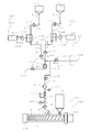
- a step of pouring the molten resin in the heating cylinder; a step of causing the first liquid and the second liquid injected into the molten resin to react in the heating cylinder to generate a gas; and the melting containing the gas And a step of injecting the resin into the mold cavity, injecting the resin into the mold, or extruding the resin through the die.
- a method of manufacturing a molded product the step of injecting a predetermined amount of liquid into the vaporizer, the vaporization temperature being equal to or lower than the temperature of the molten resin in the heating cylinder, Vaporizing the liquid in the vaporizer, injecting the gas into a molten resin in a heating cylinder, injecting the molten resin containing the gas into a mold cavity, injecting the mold, Or a step of extruding through a die.
- the method for producing a molded product according to claim 5 is the method according to claim 4, wherein the liquid includes a substance having a thermal decomposition temperature equal to or lower than a temperature of the vaporizer, and the vaporization step is performed by injecting the liquid into the vaporizer. The liquid and the substance are gasified in the vaporizer.
- a predetermined amount of the first liquid containing bicarbonate or carbonate and a predetermined amount of the second liquid containing organic acid are separately provided.
- a step of injecting into the vaporizer a step of causing the first liquid and the second liquid injected into the vaporizer to react in the vaporizer to generate gas, and the gas into the molten resin in the heating cylinder.
- an apparatus for producing a molded article wherein the vaporization temperature is equal to or lower than the temperature of the molten resin in the heating cylinder, and a predetermined amount of liquid is injected into the molten resin;
- the molded article manufacturing apparatus is the molding apparatus according to claim 7, wherein the liquid includes a substance having a thermal decomposition temperature equal to or lower than a temperature of the molten resin in the heating cylinder, and the injection apparatus and the casting apparatus.
- the extruding device is characterized in that the liquid and the substance injected into the molten resin are turned into gas in the heating cylinder.
- the apparatus for manufacturing a molded article according to claim 9 separately comprises a predetermined amount of a first liquid containing hydrogen carbonate or carbonate and a predetermined amount of a second liquid containing an organic acid.
- An apparatus for manufacturing a molded product according to claim 10 is a vaporizer that converts liquid into a gas, and injects a predetermined amount of liquid into the vaporizer, the vaporization temperature of which is equal to or lower than the temperature of the molten resin in the heating cylinder.
- a first injection device, a second injection device for injecting the gas in the vaporizer into the molten resin in the heating cylinder, and the molten resin containing the gas injected into the molten resin by the second injection device It has an injection device that injects into a mold cavity, a casting device that injects into a mold, or an extrusion device that extrudes through a die.
- An apparatus for manufacturing a molded product according to claim 11 is the apparatus according to claim 10, wherein the liquid includes a substance having a thermal decomposition temperature equal to or lower than a temperature of the molten resin in the heating cylinder, and the vaporizer includes the liquid and The substance is a gas.
- An apparatus for manufacturing a molded article according to claim 12 is predetermined, a vaporization device that generates a gas by reacting a first liquid containing bicarbonate or carbonate and a second liquid containing an organic acid.
- a first injection device that separately injects a predetermined amount of the first liquid and a predetermined amount of the second liquid into the vaporizer, and the gas in the vaporizer to the molten resin in the heating cylinder
- the method for producing a molded product according to claims 1, 2 and 3 can stabilize the quality of the foam molded product as compared with a case where a predetermined amount of liquid is not injected into the molten resin.
- the method for producing a molded product according to claims 4, 5 and 6 can stabilize the quality of the foam molded product as compared with a case where a predetermined amount of liquid is not injected into the vaporizer.
- the molded product manufacturing apparatus can stabilize the quality of the foamed molded product as compared with a case where a predetermined amount of liquid is not injected into the molten resin.
- the molded article manufacturing apparatus can stabilize the quality of the foam molded article as compared with a case where a predetermined amount of liquid is not injected into the vaporizer.
- Schematic diagram of molded product manufacturing equipment Schematic diagram of molded product manufacturing equipment Schematic diagram of molded product manufacturing equipment Schematic diagram of molded product manufacturing equipment Schematic diagram of the inlet Schematic diagram showing the inlet installation state Schematic diagram showing the inlet installation state Schematic diagram showing the inlet installation state Schematic diagram showing the means for stirring the foaming agent
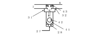
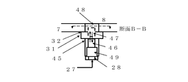
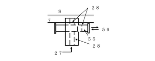
- Schematic diagram showing the structure of the inlet Schematic diagram showing the retainer of the ball check valve 42 in FIG. 14 is a schematic diagram showing a structure in which the ball check valve 42 in FIG. 14 is a cylindrical valve.
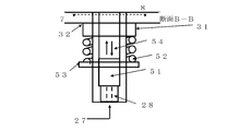
- (A) is a schematic diagram showing the cylindrical valve 46 in FIG. 16
- (B) is a BB cross-sectional view in (A).
- FIG. 1 Schematic diagram showing an example of an inlet Schematic diagram showing an example of shut-off nozzle Schematic diagram showing an example of shut-off nozzle Schematic diagram showing an example of shut-off nozzle Schematic diagram showing the structure of the seal mold Schematic diagram showing the structure of the device that pressurizes the inside of the mold cavity
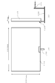
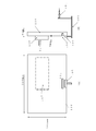
- A is a plan view of the mold
- B is a side view of the mold of
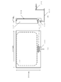
- A) is a plan view of the molded product
- (B) is a side view of the molded product of (A).
- A) is a plan view of the molded product
- (B) is a side view of the molded product of (A).
- Diagram for explaining automatic gate cut (A) is a plan view of the molded product, (B) is a side view of the molded product of (A). (A) is a plan view of the molded product, (B) is a side view of the molded product of (A).
- Schematic diagram of IGCP device (A) is a plan view of the molded product, (B) is a side view of the molded product of (A).
- Schematic diagram of molded product manufacturing equipment Schematic diagram of molded product manufacturing equipment
- Schematic diagram of molded product manufacturing equipment Schematic diagram of molds for casting and block molding
- Schematic diagram of molded product manufacturing equipment Schematic diagram of molded product manufacturing equipment
- Mold cavity refers to a space or volume filled with at least one of a foamed resin and a non-foamable resin in injection molding, block molding, or cast molding. Further, “inside the mold cavity” or “inside the cavity” means the inside, space, or volume of the mold cavity.
- injection refers to filling or filling a mold cavity with at least one of a foamed resin and a non-foamable resin.
- “Filling” refers to filling at least one of a foamed resin and a non-foamable resin in the mold cavity in the molding process. Filling less than the volume in the mold cavity is called short shot or short mold. A filling equivalent to the volume in the mold cavity is called a full shot or a full pack. Filling more than the volume in the mold cavity is referred to as overshot or overpack.
- overshot or overpack In order to reduce sink marks or improve transferability, if pressure is applied after a full shot, clearly indicate that pressure retention was used. In the case of block molding, the non-pressurization and pressurization classification clearly indicates the presence or absence of pressurization such as non-pressurization after filling and pressurization after filling.
- injection refers to a process of introducing (pouring) gas or liquid with an external force using, for example, a syringe or a pump. “Addition” simply means mixing and adding, and is broader than injection. That is, “injection” is included in “addition”.
- injection is included in “addition”.
- FIGS. 1, 2 and 3 which will be described later, an apparatus capable of controlling the injection amount of the liquid foaming agent or foaming gas is used.
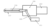
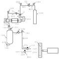
- FIG. 2 shows an injection apparatus having a vaporizer / reactor 22 that generates a foamable gas by vaporizing (gasifying) and thermally decomposing a liquid foaming agent by a thermal action.
- the vaporizer / reactor 22 is equipped with a cleaning mechanism for removing the residue inside.
- the foaming residue in the vaporizer / reactor 22 is washed by the following means. That is, in FIG. 2, the automatic opening / closing valve 158 that is open at the time of foam molding is closed so that the cleaning liquid does not enter the heating cylinder 7.
- the automatic open / close valve 159 that is normally closed and the automatic open / close valve 153 for discarding the cleaning liquid are opened, and the cleaning liquid, for example, an organic solvent such as water, ethanol or the like is opened from the inlet 155. Insert.
- the vaporizer / reactor 22 is filled with a cleaning solution, and if necessary, the residue inside the vaporizer / reactor 22 is heated so as to be easily dissolved, and is vibrated with an ultrasonic wave from the outside, or air or nitrogen inside. Gas is introduced and bubbled to dissolve the foaming residue in the cleaning liquid, which is then discharged to the outside through the cleaning liquid outlet 156.
- the cleaning liquid used is preferably the solvent used in the apparatus, but other cleaning liquids may be used. Residue when pyrolysis of bicarbonate such as baking soda or potassium bicarbonate is carbonate, so in addition to dissolving with water, put organic acid aqueous solution such as citric acid aqueous solution to cause chemical reaction. There is a way to remove it.
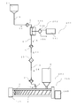
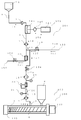
- FIG. 3 is a schematic diagram of an apparatus for manufacturing a molded article including a vaporizer / reactor 22 that mixes a liquid foaming agent and vaporizes it by at least one of a chemical reaction and heating to generate a foamable gas.
- the foaming gas is carbon dioxide
- it is liquefied when pressure is applied below the critical temperature. Therefore, in order to inject carbon dioxide gas into the heating cylinder as it is, the components from the vaporizer / reactor 22 to the heating cylinder are added. Need to warm up.
- the vaporizer / reactor 22 is provided with a cleaning mechanism for removing residues inside the vaporizer / reactor 22.
- “Plasticization” means, for example, heating a thermoplastic resin in a heating cylinder and melt-kneading it using a screw or the like, or heating to melt.
- Melting”, “melting” and “melting” refer to the substance being heated to a liquid. In other words, “melting”, “melting”, and “melting” refer to a phase change in which a solid phase material is heated to become a liquid phase. The temperature at which a solid turns into a liquid is called the melting point. Thermoplastic resins do not have a melting point, but the concept close to the melting point has a softening point. “Melting” refers to heating a thermoplastic resin to the softening point. In the present invention, “melting”, “melting” and “melting” are treated as synonyms.
- the “heating cylinder” is a plasticizing device, kneading device, or injection device of an injection molding machine, or a plasticizing device, kneading device, or extrusion device of an extrusion molding machine. In the case of processing, it means an external heater provided.
- the heating cylinder is also called a barrel, a cylinder, a housing, a casing, or the like. In the case of a thermosetting resin, at least one of a heater and a cooler is provided outside the “heating cylinder” as necessary.
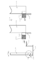
- “Injection into the heating cylinder” means that the heating cylinder is processed and the injection port (valve) 5 shown in FIGS. 1 to 3, 34 to 36, 38, 39, or 5 to 7 is provided.
- the injection port (valve) 5 shown in FIGS. 1 to 3, 34 to 36, 38, 39, or 5 to 7 is provided.
- the present invention there is also a method of injecting at least one of the liquid foaming agent and the foamable gas into the molten resin in the heating cylinder through the screw through the hole formed in the rear part of the screw. Absent.
- the hopper is covered with a lid at the bottom of the hopper for each molding (one shot). It is desirable to seal the foaming gas so that it does not escape.
- the high-temperature liquid foaming agent is the thermoplastic resin.
- the thermoplastic resin This causes a problem that a part of the pellets is melted and the pellets are joined (adhered) to each other.
- the molding material cannot be injected into the mold cavity or the like (sent into the heating cylinder).
- excess liquid blowing agent solvent such as moisture
- vacuuming vacuuming
- “Resin in the heating cylinder” means a solid (solid) state such as pellets, bulk, and powder before heating and melting, a stage during plasticization, a thermoplastic resin in a molten state after plasticization is completed, or thermosetting refers to a functional resin.
- “foam molding” refers to molding a molded product having a foam structure using any one of the following methods (A) to (E).
- the liquid foaming agent of the present invention for example, an aqueous solution of water, alcohols, sodium bicarbonate, potassium hydrogen carbonate, citric acid, sodium citrate, etc. is injected into the heating cylinder, and the molten resin in the heating cylinder has foaming properties. How to make.
- E Manufactured using a solid foaming agent such as sodium bicarbonate powder, citric acid powder, azodicarboxylic acid amide powder of the present invention, or a resin having the same quality as or compatibility with the resin to be molded. A method for imparting foamability to a molten resin in a heating cylinder using a master batch of a foaming agent.
- foam molding is a mixture of commercially available foaming agents and liquid foaming agents, and is heated before, during, and after filling, to vaporize, pyrolyze, and chemically It means foaming by means of reaction or the like to mold the molded product of the foam structure.
- the foaming agent having three properties of gas, liquid or solid may be used alone or in combination in foam molding.
- thermoplastic resin When using a liquid foaming agent for the thermoplastic resin, measure (measure) the optimum capacity with respect to the weight of the molded product, inject it into the thermoplastic resin in the heating cylinder, Depending on at least one of the temperature of the molten thermoplastic resin in the heating cylinder and the temperature of the mold, at least one of vaporization, thermal decomposition and chemical reaction, or at least decomposition and chemical reaction without the need for heat. One is used to generate gas useful (effective) for foaming.
- the generated gas causes at least one of fine dispersion and pressure dissolution in the thermoplastic resin in the heating cylinder. If it does so, the thermoplastic resin in a heating cylinder will become a thermoplastic resin which has foamability. This can be injected into the mold cavity to produce a molded product having a foam structure, or extruded to obtain a foam molded product.
- foam molding refers to a foam structure in which a foaming structure is generated by dispersing and dissolving a liquid foaming agent in a resin in a heating cylinder and generating useful foaming gas depending on the temperature of the mold. Say getting the body and the process. In particular, the latter is mainly used in block molding or casting molding of a thermoplastic resin or molding processing of a thermosetting resin.
- Gas is a fluid together with a liquid, the thermal motion of molecules exceeds the intermolecular force, and the molecules can move freely compared to the liquid state.
- the volume of gas varies greatly with pressure and temperature.
- gas does not have a fixed volume, fills it when placed in a container, is rich in fluidity, and has the property of always spreading itself.
- the density of the gas is smaller than that of solid and liquid, and can be easily compressed.
- the volume of gas is proportional to temperature and inversely proportional to pressure.
- “Vapor” refers to a state in which a substance is evaporated from a liquid and sublimated from a solid into a gas. In particular, substances below the critical temperature are referred to as the gas phase. “Vaporization” refers to a phenomenon in which a substance changes from a liquid or solid to a gas. Evaporation includes evaporation and boiling. Evaporation is a phenomenon that vaporizes from the surface of the liquid and boiling occurs from the inside of the liquid. “Boiling point” refers to the temperature at which boiling occurs. The boiling point increases as the pressure increases. “Coagulation” refers to a physical change in which a gas becomes a liquid, also called “condensation”.
- Condensation point refers to the temperature at which the gas becomes liquid, and the higher the pressure, the higher the condensation point.
- the condensation point in the case of water is particularly called “dew point (dew point temperature)”.
- the condensation of water on the surface of an individual is called “condensation”.
- sodium bicarbonate water is used as the liquid blowing agent, the solvent water is condensed on the surface of the mold because the surface temperature of the mold is lower than the dew point temperature. To reduce condensation, increase the mold surface temperature. If the mold surface temperature is raised above the dew point, condensation will not occur.
- OGCP is used, the dew point temperature becomes high, so the surface temperature of the mold must be further increased.
- a low-boiling liquid foaming agent such as diethyl ether
- the condensation of the solvent on the mold surface is solved.
- a low-boiling substance and a high-boiling substance for example, a mixture of diethyl ether, water, and ethanol
- the amount of high-boiling substances used in the liquid blowing agent is reduced, so the condensation problem of the solvent is alleviated. .
- Liquid is a state in which molecules are attracting each other, but it is fluid, changes shape according to the container, and exhibits fluid properties similar to gas, but is less compressible than gas. So follow Pascal's principle. The liquid maintains a substantially constant density and, unlike gas, does not spread throughout the container. Liquids have surface tension as a unique property such as forming their own surface. Intuitively, “solid” if the shape is constant, “liquid” if the shape is not constant but the volume is constant, and “gas” is that the shape and volume are not constant.
- Liquid blowing agent has its own temperature in the range of minus 40 ° C. to plus 150 ° C. and pressure in the range of 0.01 MPa to 25 MPa ⁇ the point where the temperature and pressure are determined (original, lower ) ⁇ Refers to a substance exhibiting the above-mentioned liquid properties.
- the liquid foaming agent may be liquid at the stage of normal use, for example, when it is injected into the heating cylinder, or at the stage of injection into the vaporizer / reactor 22 shown in FIGS.
- the liquid foaming agent is, for example, a measurement of the injection capacity with respect to the weight of the resin per shot in the injection molding of a thermoplastic resin and the extrusion weight of the resin per certain time in the extrusion molding process. Is required to be possible.
- the liquid foaming agent is water, alcohols, a mixed solution of water and alcohols, carbonated water, an aqueous solution of bicarbonate, an aqueous solution of carboxylic acid, an aqueous solution of carboxylate, ethers, Liquids typified by mixed solutions of water and ethers, etc., including emulsions (emulsions), suspensions (suspensions), sols or gels, in which other substances are added and mixed together.
- liquid substances typified by mixed solutions of water and ethers, etc., including emulsions (emulsions), suspensions (suspensions), sols or gels, in which other substances are added and mixed together.
- liquid substances typified by mixed solutions of water and ethers, etc.
- liquid liquid and “liquid” are synonymous.
- the “injection amount” means that the capacity of the liquid foaming agent to be injected is determined for a certain weight of resin.
- “Volume” refers to the volume (vol), weight (wt), or mass measured by a device such as a syringe or a scale. Since the acceleration of gravity on the earth is substantially constant 9.8 Newton (N), weight and mass are synonymous.
- Control refers to injecting a predetermined volume of a liquid foaming agent into a certain amount of resin.
- Weighting or “charging” refers to measuring the capacity by some means. Although molding is also referred to as metering, this means that the capacity of the resin can be measured by the rotational speed of the screw or the receding distance.
- Foaming means a liquid foaming agent, a commercially available foaming agent that is useful for foam molding by physical change such as vaporization, thermal decomposition, chemical reaction, etc., such as water vapor, alcohol vapor (gas), ether This refers to the generation of vapors of organic solvents, vapors of organic solvents, carbon monoxide, carbon dioxide gas, nitrogen gas, hydrogen gas, and the like.
- “foaming” refers to a state in which the foaming gas is suppressed by external pressure such as IGCP, OGCP, back pressure, injection pressure, etc. From the state where at least one of the pressure dissolution is performed), the pressure from the outside decreases or disappears, the volume of the foamable gas in the resin increases, or the foamed gas dissolved under pressure becomes a gas Say.
- “foaming” includes a case where a foamed thermoplastic resin is extruded from a heating cylinder to foam, or a case where a thermosetting resin is heated in a mold cavity to foam.
- a process in which a foaming gas is generated by a liquid foaming agent or a solid foaming agent by vaporization, thermal decomposition, or chemical reaction is also referred to as “foaming”.
- foaming means that the foaming gas is finely dispersed and / or pressure-dissolved in the molten thermoplastic resin, and the pressure is lowered to reduce the pressure inside the surface and the surface of the thermoplastic resin. It is said that at least one of the foam cells is formed.
- “foaming” means heating the foaming agent to cause the foaming agent to vaporize, pyrolyze, and chemically react to generate a foaming gas, and the inside and surface of the thermosetting resin. This means that at least one foam cell is formed.
- a molded product having a foamed layer inside or outside by foaming is called a foamed molded product.
- the “foamable resin” refers to a thermoplastic resin in a molten state in which at least one of a foaming gas useful for foam molding is finely dispersed and pressure-dissolved.
- the “foamable resin” refers to a thermoplastic resin or a thermosetting resin containing at least one of a liquid foaming agent and a commercially available foaming agent.
- thermoplastic resin having a foaming property in a molten state such as "a thermoplastic resin having a foaming property in a molten state", "a thermoplastic resin containing a foaming agent, or a thermosetting resin containing a foaming agent” has been given foaming properties
- the state of the resin is described as accurately as possible, such as containing at least one of a liquid foaming agent and a commercially available foaming agent.
- “Foamed molded product” refers to a resin molded product having discontinuous foamed cells (cells) formed by molding using a thermoplastic resin or a thermosetting resin having a foaming property.
- the foam cell has a size of 1,000 ⁇ m (micron, micrometer) or less. In the present invention, a foamed molded product is formed even when the hollow portion and the foamed cell coexist.
- “Combination” means not only that, but also use with other things. For example, many molding methods are described in the specification of the present invention. Although one of these molding methods is effective, it can be used in combination with another method, and a synergistic effect can be obtained, or improvement of one or both effects can be expected.
- liquid foaming agents may be used in combination of several types instead of alone. Sometimes used in combination with commercially available foaming agents.
- Foaming agents are roughly classified into physical foaming agents and chemical foaming agents, and there are inorganic and organic products, respectively.
- Foaming agents include hydrogen carbonate, carbonate, nitrite, hydrogen compound carboxylic acid, carboxylate, etc. in the inorganic thermal decomposition type of chemical foaming agents, and organic thermal decomposition type azo compounds and hydrazine derivatives.
- Semicarbazide compounds, azide compounds, nitroso compounds, triazole compounds, etc., and reactive types include isocyanate compounds.
- liquid foaming agent “commercially available foaming agent”
- solid foaming agent solid foaming agent
- foaming agents include, for example, polyslen, fine blow (both are trade names and solid properties are pellets) as a master batch of the foaming agent.
- a master batch of a foaming agent is produced using an inorganic foaming agent or an organic foaming agent and a resin to be molded.
- Examples of the inorganic foaming agent include carbonates represented by sodium carbonate, sodium carbonate, bicarbonates represented by potassium bicarbonate, carboxylic acids, carboxylates, organic acids, sodium dihydrogen citrate, citric acid 2 Organic acid salts represented by hydrogen potassium.
- Examples of the organic foaming agent include ADCA (azodicarboxylic amide, azodicarbonamide), HDCA (hydrodicarboxylic amide, hydridicarbonamide), barium azodicarboxylate, OBSH ⁇ PP′-oxybis (benzenesulfonylhydra). Zid) ⁇ , DPT (dinitrosopentamethylenetetramine), AIBN (azobisisobutyronitrile) and the like. Details of the foaming agent and foam molding are described in various polymers and foam molding technology issued in August 1993 by the Technical Information Association.
- the properties of the foaming agent that can be used in the present invention are liquid (liquid), not pellets or powder.
- the volume of the liquid can be measured using a device such as a syringe, or a plunger pump or a diaphragm pump whose flow rate can be confirmed, and the volume can be controlled.
- the liquid foaming agent that can be used in the present invention refers to a substance that generates a foaming gas through a chemical reaction by mixing without being vaporized, thermally decomposed, chemically reacted, or thermally activated by a thermal action.
- the liquid blowing agent include water, monohydric alcohols, polyhydric alcohols, ethers, esters, ketones, aliphatic hydrocarbons, aromatic hydrocarbons and the like. They can be used alone or as a mixed solution of two or more.
- the liquid blowing agent also includes an azeotropic mixture such as a mixed solution of 96 wt% ethanol and 4 wt% water.
- azeotropic mixture indicates an azeotropic point like a single substance when the substances to be mixed interact with each other.
- the mixture of water and ethanol used in the present invention is an azeotropic mixture.
- an azeotrope When using an azeotrope as a liquid blowing agent, one of the substances may act as a foam nucleating agent.
- Liquid foaming agents include carbonates (eg, sodium carbonate, potassium carbonate, etc.), bicarbonates (bicarbonate: eg, sodium bicarbonate, potassium bicarbonate, etc.), nitrites, nitrates, carboxylic acids (eg, Citric acid, malic acid, tartaric acid, etc.), carboxylates (eg, sodium dihydrogen citrate, potassium dihydrogen citrate, etc.), aqueous solutions of sodium azide, monohydric alcohols and organic solvents such as pentane or hexane, etc. And a mixed solution of an aqueous solution of the carbonate, hydrogen carbonate, carboxylic acid, carboxylate, and the like and an alcohol.
- carbonates eg, sodium carbonate, potassium carbonate, etc.
- bicarbonates eg, sodium bicarbonate, potassium bicarbonate, etc.
- nitrites egrates
- carboxylic acids eg, Citric acid, malic acid, tartaric
- the aqueous solution of these salts needs to have a concentration that does not normally precipitate. If an aqueous solution of these salts is precipitated, it is heated and redissolved. An aqueous solution of these salts may be used while heating the aqueous solution in order to increase the solubility.
- the solubility of sodium bicarbonate or potassium bicarbonate increases as the temperature rises. Therefore, the tank 1 and the syringe 11 into which the liquid foaming agent shown in FIGS. Heat to increase solubility. Further, in FIGS. 34 to 36 and 39, the tanks 1 and 145 in which the liquid foaming agent is placed and the piping through which the liquid foaming agent passes are heated for the purpose of increasing the solubility as necessary.
- ADCA, DPT, etc. which are organic pyrolytic foaming agents, are insoluble in water or alcohols, low boiling point organic solvents useful for foam molding, etc., so they are used as a suspension and useful for foam molding.
- the low boiling point organic solvent and water are used as an emulsion (emulsion).
- emulsion emulsion
- Aqueous carbon dioxide (carbonated water), liquefied carbon dioxide, liquefied propane, and liquefied butane are also useful liquid blowing agents.
- carbon dioxide gas generated by contact of a solid of a basic substance such as carbonate or carbonate or an aqueous solution thereof with an aqueous solution of an inorganic acid or an organic acid is also shown in FIG. If an apparatus is used, it can be used as a foaming gas, so if either one is liquid, it is included in the liquid foaming agent. Since carbon dioxide gas is liquefied when it is pressurized below the critical temperature and sent to be injected into the heating cylinder, the vaporizer / reactor 22 in FIGS. 3 and 36 and the piping to the heating cylinder thereafter Heat above the critical temperature.
- the above reaction can be carried out, for example, by controlling the capacity of one of the hydrogen carbonate or bicarbonate aqueous solution and citric acid or citric acid aqueous solution, each of which is a liquid in a heating cylinder, without using the production apparatus of FIG.
- Stable foam molding can be performed by injecting and generating carbon dioxide gas.
- hydrogen gas can be generated by contact of a metal, an acidic substance, and a basic substance and used as a foaming gas.
- the liquid foaming agent is liquid when in use, and is vaporized by thermal action when injected into the heating cylinder 7 or the vaporizer / reactor 22 in FIGS. 1, 2, 35, 36, 38, and 39.
- the foamable gas is generated by at least one of physical changes such as thermal decomposition and chemical reaction. Further, the liquid foaming agent is mixed with the resin and foamed by heating in the mold cavity.
- liquid blowing agent examples include aliphatic alcohols such as water, carbonated water, methanol, ethanol, propanol, butanol, and decanol, such as primary, secondary, and tertiary monohydric alcohols, and polyhydric alcohols.
- An aliphatic ether such as diethyl ether, methyl propyl ether, ethyl propyl ether, methyl butyl ether and ethyl butyl ether, an ether such as a cyclic ether such as tetrahydrofuran, pentane, and the like.
- Aliphatic hydrocarbons such as hexane, aromatic hydrocarbons such as benzene, toluene and xylene, ketones represented by n-butanone (methyl ethyl ketone, MEK), esters such as ethyl acetate and butyl acetate, chloride Methylene, chloroform, carbon tetrachloride Alone substances called organic solvent selected from such as chlorides of aliphatic hydrocarbons, or a mixture of two or more thereof may be exemplified.
- the liquid blowing agent that is injected into a heating cylinder of a molding machine and vaporizes to generate a foaming gas preferably has a boiling point equal to or lower than the temperature of the molten resin, such as water, alcohols, and ethers.
- the surface temperature of the mold is higher than the dew point temperature of the liquid foaming agent to be used, part of the liquid foaming agent does not condense on the mold surface, so that the occurrence of sink marks due to this condensation is reduced.
- the liquid foaming agent is a mixture of water and the above-mentioned organic solvent, a mixture of organic solvents, water, or carbonate, sodium bicarbonate, bicarbonate represented by potassium bicarbonate, nitrite, Chemical formulas represented by nitrates, borohydrides represented by sodium borohydride, inorganic azides represented by sodium azide, acetic acid, butyric acid, oxalic acid, malic acid, citric acid and the like are R- An organic acid typified by carboxylic acid represented by COOH, an aqueous solution or suspension of an alkali metal salt of the carboxylic acid, a substance insoluble in water, such as benzene and xylene, is a milk using a surfactant.
- liquid foaming agent used in the present invention may be referred to as a liquid foaming agent or a liquid foaming agent.
- Baking soda, bicarbonates typified by potassium bicarbonate, organic acids such as citric acid, citrate, etc. are made into an aqueous solution and injected into a heating cylinder of a molding machine as a liquid foaming agent. It is desirable that the temperature of the solute thermal decomposition and the vaporization temperature of the solvent are both lower than the temperature of the molten resin.
- the liquid foaming agent is vaporized and thermally decomposed depending on the temperature of the heating cylinder.
- the liquid foaming agent is a vaporizer (evaporator) that measures the volume before being injected into the heating cylinder 7 and vaporizes or thermally decomposes by applying heat to the volume-controlled liquid foaming agent.
- Carburetor) / reactor (generator) 22 and there is a method of injecting gas effective for foam molding into the heating cylinder 7.
- the foaming gas is generated by thermally decomposing the liquid foaming agent before injection into the heating cylinder 7, the foam residue remains in the vaporizer / reactor 22 and does not enter the molded product. Can solve the problem.
- thermosetting resin In the case of a thermosetting resin, a liquid foaming agent is mixed with the thermosetting resin to be molded in advance, and foaming is performed at the stage of heating in the mold cavity for injection molding and at the stage of heating of the die for extrusion molding. Can be made.
- the composition, concentration, and the like of the liquid blowing agent are determined by, for example, the mixing ratio of at least two or more mixtures selected from water, alcohols, and ethers, the concentration of sodium bicarbonate in sodium bicarbonate, or the injection amount.
- pouring a liquid foaming agent is determined by resin to be used, molding conditions, a molding method, the shape of a molded article, etc. In addition, it is necessary to consider solubility in the production of these mixtures and aqueous solutions.
- liquid foaming agents carbonate and hydrogen carbonate aqueous solutions generate carbon dioxide gas upon contact with inorganic acids (inorganic acids) and organic acids (organic acids).
- inorganic acids inorganic acids
- organic acids organic acids
- 3 and 36 are used when a carbon dioxide gas is generated by the reaction of the above-described carbonate, hydrogen carbonate, inorganic acid, and organic acid, and used as a foaming gas.
- the vaporizer / reactor 22 is heated, and simultaneously with the chemical reaction, the solvent water may be vaporized to form a foamable gas.
- thermoplastic resin with foamability in the molten state increases, so that low-pressure molding is possible by injection molding, and transferability is improved. And has an effect.
- liquefied carbon dioxide and liquid nitrogen are liquid when in use, they can be used depending on the molding means.
- a substance having a property of sublimating such as dry ice or naphthalene can be used as a foaming agent, and therefore can be used in combination with a liquid foaming agent.
- Foaming gas refers to a gas generated by vaporization, thermal decomposition, or chemical reaction of a commercially available foaming agent typified by ADCA or a liquid foaming agent.
- the foaming gas has a pressure of 1 atm (760 mm / Hg) and a temperature of 75 based on the pressure in the heating cylinder, the mold cavity, the temperature of the resin (moldable resin temperature), and the temperature of the mold or die. Any gas may be used as long as it is a gas having a capacity of foaming the resin described in the present invention in a gas of not lower than ° C.
- Ether vapors, vapors of organic solvents such as pentane and hexane, propane, butane gas and the like are useful.
- One type of foaming gas may be used, but since there are differences in the action on the resin such as fine dispersion and dissolution depending on the gas, several types may be used in combination.
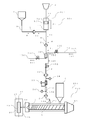
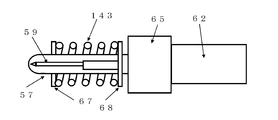
- liquid foaming agent injection apparatus For easy understanding, the use of the liquid foaming agent in the injection molding of the thermoplastic resin shown in FIG. 1 will be described.
- the liquid foaming agent measures the optimum capacity for one injection amount, is directly injected into the molten thermoplastic resin in the heating cylinder 7, and is vaporized, pyrolyzed and chemically reacted by the heat of the heating cylinder 7. At least one is performed to generate a foaming gas.
- the liquid foaming agent is generally injected into the heating cylinder 7 from the injection ports 5 provided in the heating cylinder 7.
- Reference numeral 1 denotes a tank for storing a liquid foaming agent.
- the liquid foaming agent in the tank 1 is fed into the injection device 4 through the piping 9 by the pressure of the liquid foaming agent and the suction operation of the injection device 4 or by pressurizing the inside of the tank 1 in advance.
- the injection device 4 is a drive device 3 of the plunger 12, for example, a servo motor, a hydraulic cylinder, a pneumatic cylinder, or the like, and measures the volume of the liquid foaming agent to be injected into thermoplastic fat to be measured (plasticized) next ( Weighing). Either one shot can be injected into the heating cylinder 7, or the volume of a large amount of liquid foaming agent can be measured at one time, and the required amount can be injected for each shot.
- the injection is (A) Put in the heating cylinder 7 at once, or put in several times, (B) Insert continuously from the start to the end of weighing. (C) The injection is started after a predetermined time has elapsed from the start of measurement, and then the injection is stopped after a further predetermined time has elapsed. (D) After a predetermined time has elapsed from the start of measurement, injection is started, and then the injection is stopped at the end of measurement. (E) Stop the injection a little after the end of weighing, and so on. In the case of extrusion, the injection is usually continued.
- the driving device 3 of the external plunger 12 When plasticizing (measuring) of the thermoplastic resin is started, the driving device 3 of the external plunger 12 is moved, the plunger 12 is lowered, and injection of the liquid foaming agent into the heating cylinder 7 is started.
- the injection port (valve) 5 is devised, for example, as shown in FIGS. 10 to 19 so that it does not flow back to the injection device 4 even when the pressure of the molten thermoplastic resin in the heating cylinder 7 increases.
- Reference numeral 6 is a hopper for containing the material
- reference numeral 7 is a heating cylinder
- reference numeral 8 is a mixture of plasticization of a thermoplastic resin and a liquid foaming agent, foamed, and finely disperse the foaming gas in the molten thermoplastic resin.
- a screw for pressurizing and dissolving reference numeral 16 is a shut-off nozzle mounted for the purpose of preventing nose sagging during measurement, and reference numeral 10 is a mold cavity.
- the injection device 4 for injecting the liquid foaming agent into the heating cylinder 7 has a syringe (cylinder) 11 and a plunger (presser) 12.
- the plunger 12 is connected to the drive device 3 of the plunger 12, and immediately after receiving a measurement start signal from the injection molding machine 204, or after a certain time has passed, the injection of the liquid foaming agent into the heating cylinder 7 is started.
- the speed of injection (volume of injection per hour) may be entered at once, but is preferably synchronized with at least one of the speed of metering and the position of the screw 8 of the injection molding machine. The injection is stopped before, when, or after metering (rotation of the screw 8) stops.
- the plunger 12 is provided with a plunger ring 13 so that the liquid foaming agent does not leak out of the syringe 11 (upper part of the drawing in FIG. 1).
- Plunger ring 13 may be an O-ring, but slidable Teflon (registered trademark) or high-density PE such as omni seal (trade name) or burr seal (trade name) whose pressure becomes higher when pressure is applied. It is preferable to use a material having the characteristics.
- the number of the plunger rings 13 may be one, it is desirable to use a plurality of types and a plurality of types in order to improve the sealing performance.
- a slide ring (not shown) or the like may be provided.
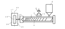
- FIG. 2 and 35 show a molded product manufacturing apparatus in which the molded product manufacturing apparatus 201 shown in FIG. 1 is provided with a vaporizer / reactor 22.
- the vaporizer / reactor 22 is charged with a liquid foaming agent and then heated from the outside with a heater or the like to generate at least one of vaporization, thermal decomposition, and chemical reaction to generate a foamable gas.
- high frequency induction heating was used.
- This foaming gas is injected into the heating cylinder 7 by adjusting the pressure with the pressure adjusting valve 23 as necessary.
- a diversion adjusting valve 26 is provided.
- Reference numeral 24 is a pressure before injection
- reference numeral 25 is a pressure gauge for a foaming gas injected into the heating cylinder.
- the concept of the vaporizer / reactor 22 shown in FIG. 2 and FIG. 35 is used, for example, powder ADCA is put into the vaporizer / reactor 22 and then heated from the outside to thermally decompose ADCA to generate gas. If the foam residue is recovered and discarded, the problem that the residue remains in the molded product even when ADCA is used is solved. If water is passed through in the middle, the ammonia gas contained in the foamable gas can be removed.
- the vaporizer / reactor 22 is not necessarily used. And vaporize.
- the foaming gas may be put into the heating cylinder 7 by being vaporized in the vaporizer / reactor 22.
- the foamable gas vaporized as necessary is adjusted in pressure by the pressure adjusting valve 23 and injected into the heating cylinder 7.
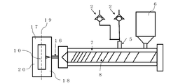
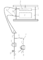
- FIG. 3 and FIG. 36 show an apparatus for generating a foamable gas useful for foam molding by chemically reacting a liquid foaming agent.
- a means for generating carbon dioxide gas by a chemical reaction between an aqueous sodium bicarbonate solution and an aqueous citric acid solution will be described.
- a sodium bicarbonate solution is placed in the tank 1 shown on the left side of FIG. 3 and an aqueous citric acid solution is placed in the tank 1 shown on the right side of FIG. Thereafter, each plunger is operated to put sodium bicarbonate water and an aqueous citric acid solution into the vaporizer / reactor 22 to generate carbon dioxide gas inside the vaporizer / reactor 22.
- the pressure of the carbon dioxide gas is adjusted by a pressure adjusting valve (regulator) 23 and injected into the heating cylinder 7.
- a flow rate adjustment valve 26 is provided. If this apparatus is applied, a solid substance such as CaCO 3 can be put in the vaporizer / reactor 22 to generate carbon dioxide gas using hydrochloric acid or the like to be used as a foaming gas. If this apparatus is applied, hydrogen generated by bringing hydrochloric acid into contact with metal zinc and sodium hydroxide aqueous solution into contact with metal aluminum can also be used as the foaming gas.
- the molded product manufacturing apparatus shown in FIGS. 1 to 3 and 38 is an injection molding machine 204.
- 34 to 36 and 39 is an extruder 206.
- the foamable resin obtained with this apparatus is normal pressure (non-pressurized), pressurized block molding, and casting (form). It can also be used in calendar molding, lamination molding, etc., and a molded product can be produced.
- symbol 2 in FIG. 1 is a check valve, and prevents the backflow of a liquid foaming agent. 1 to 3, FIG. 38, FIG. 34 to FIG. 36, and FIG. 39 can be used for manufacturing a molded product using a thermosetting resin. In this case, mainly mold or die is heated
- FIGS. 1 to 3 and FIG. 38 shows a process of measuring the volume of the liquid foaming agent for each shot of the injection molding process.
- the injection amount may be determined by the movement.
- an automatic opening / closing valve (not shown) is installed upstream of the injection port 5 as necessary.
- FIG. 1 shows injection molding
- FIG. 34 shows extrusion molding.
- Means for injecting one type of liquid foaming agent into the heating cylinder 7 is shown.
- the tank 1 and the injection device 4 are prepared for the types of liquid blowing agents.
- each liquid foaming agent is mixed in front of one inlet 5 (upstream side) and injected into the heating cylinder 7, a plurality of inlets 5 are provided in the heating cylinder 7, and You may inject
- the number of injection ports 5 is not necessarily one, and liquid foaming agents may be injected from a plurality of injection ports 5.
- the installation (attachment) location of the injection port 5 to the heating cylinder 7 may be the same or different distance from the tip of the heating cylinder 7, for example, anywhere in the circumferential direction of the heating cylinder 7 at the same location. Good.
- FIG. 4 shows details of the injection port 5.
- the liquid foaming agent is not necessarily a mixed solution, and for example, water and ethanol may be injected into the heating cylinder 7 from separate injection ports 5.
- FIG. 5 illustrates a configuration in which two injection ports 5 are provided in the heating cylinder 7 and one kind of liquid foaming agent is injected from the two injection ports 5.
- FIG. 6 exemplifies a configuration in which two injection ports 5 are provided in the heating cylinder 7 and two different liquid foaming agents are respectively injected from the two injection ports 5. In this case, the injection of the respective foaming agents may or may not be simultaneous.
- FIG. 7 shows a configuration in which one injection port 5 is provided in the heating cylinder 7 and two different liquid foaming agents are injected from the one injection port 5.
- the injection of the respective foaming agents may or may not be simultaneous.
- 5 and 6 show two inlets, but more inlets 5 may be installed. Moreover, you may implement combining the structure of FIG. 5 thru
- ADCA, HDCA, DPT, etc. are hardly soluble or insoluble in water and alcohols. For this reason, when using these, dope cement is made with resin compatible (soluble) with the resin to be molded and dispersed therein. Although it can be used as it is, it may be used after the viscosity is adjusted by adding water or alcohol to adjust the viscosity.
- n-butanone is added to an AS resin pellet compatible with ABS, and the mixture is allowed to stand at room temperature and dissolved to form a dope cement.
- ADCA powder powder (powder) is mixed in it to enter ADCA, and a suspended sol-like liquid foaming agent is obtained.
- n-butanone or the like is added.
- a separately prepared high viscosity AS dope cement is added to adjust the viscosity.
- the liquid foaming agent using the ADCA-containing dope cement can be used as a liquid foaming agent for these resins having compatibility with AS, ABS, PC and the like.
- AS is changed to PS, it becomes a liquid foaming agent for PS, HIPS (high impact polystyrene), m-PPE and the like.
- foaming nucleating agents materials ⁇ foaming nucleating agents (materials) ⁇ and reactive foaming agents, in addition to means for injecting them separately into the heating cylinder 7 as described above, only these materials are molded.
- the resin to be molded is melt-kneaded with the resin to be molded, which is attached to the resin to be planned, is made into a master batch using the resin to be molded.
- baking soda and citric acid are made into separate aqueous solutions, each of which is injected into the heating cylinder 7 as shown in FIG. 6 or 7, and mixed in the heating cylinder 7 to cause a chemical reaction to generate foaming gas.
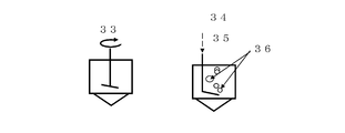
- FIG. 8 shows a means for stirring the foaming agent in the form of an emulsion or suspension. This mechanism is mainly used inside the tank 1 for storing the liquid foaming agent.
- the most useful gas for foam molding is water vapor, carbon dioxide or nitrogen gas.
- water vapor can be easily generated by vaporization of water, thermal decomposition of bicarbonate, carboxylic acid or the like, or chemical reaction with an organic acid or the like.
- Nitrogen gas is obtained by thermal decomposition of inorganic azide compounds typified by sodium azide and the like, ADCA, DPT and the like. Although the toxicity of the azide compound is a concern, an aqueous solution that is easy to handle is used, and nitrogen gas is generated using the apparatus shown in FIG. 1, FIG. 2, FIG. 34, and FIG. Since ADCA and HDCA have low toxicity, they are attached to a foaming agent master batch or resin pellets to be molded. The nitrogen gas necessary for foaming is thus obtained by conventional means, and the amount of the foaming agent master batch or the like is reduced by the combined use with the liquid foaming agent.
- inorganic azide compounds typified by sodium azide and the like, ADCA, DPT and the like.
- Alcohol vapors and ether vapors can be used as useful foaming gases.
- the alcohol vapor and the ether vapor can be generated by heating and vaporizing the liquid alcohol or ether.
- the liquid foaming agent can be used in combination with the aforementioned MuCell or the like.
- the aqueous solution of sodium bicarbonate sodium bicarbonate water
- a mixed gas of nitrogen gas, carbon dioxide and water vapor can be obtained.
- it is reduced to some extent, for example, variation in the injection amount (variation in the injection amount of the gas in which only the pressure is set), which is a problem such as MuCell.
- Foaming aid refers to a substance used for the purpose of lowering the decomposition temperature of the foaming agent or promoting the decomposition of the foaming agent.
- foaming aids for organic foaming agents include zinc stearate, barium stearate, metal soap, urea, zinc white, and inorganic and organic acids used to decompose carbonates and bicarbonates. It can be said that it is an agent.
- Foaming nucleating agent (bubble nucleating agent, foaming nucleating agent) is mixed with the resin to be molded or the liquid foaming agent used in the present invention for the purpose of foaming or forming fine foamed cells. It is a substance.
- Foam nucleating agents include, for example, oxides such as silica, talc, alumina, titanium oxide, zinc oxide and magnesium oxide, carbonates such as lithium carbonate, sodium carbonate, potassium carbonate, zinc carbonate, calcium carbonate, barium carbonate and magnesium carbonate.
- Sulfates such as calcium sulfate and barium sulfate
- hydrogen carbonates such as sodium hydrogen carbonate, sodium hydrogen carbonate, ammonium hydrogen carbonate
- sodium dihydrogen citrate monosodium citrate used as a blowing agent
- monohydrogen citrate 2 Sodium (disodium citrate), trisodium citrate (trisoda citrate), potassium dihydrogen citrate (monopotassium citrate), potassium dihydrogen citrate (dipotassium citrate), tripotassium citrate (tripotassium citrate) Alkaline of hydroxy acid represented by potassium) Metal salts, more foaming agent ADCA, DPT, and the like OBSH.
- Foam nucleating agents for example, talc, alumina, magnesium oxide, calcium carbonate, calcium sulfate, barium sulfate, etc.
- liquid foaming agents for example, water, alcohols, ethers, etc.
- resin additives for example, pigments also act as a foaming nucleating agent.
- “Foaming ratio” is a value obtained by subtracting the weight of the foam molded product from the weight of the solid molded product, dividing the value by the weight of the solid molded product, and multiplying by 100.
- the expansion ratio is a reference value for determining whether a foam layer is formed and a foam structure is formed.
- “Foaming agent mixing ratio” refers to the ratio of the weight or capacity of the liquid foaming agent to 1 and the weight or capacity of the resin to be molded, and is expressed as the ratio of the foaming agent contained in the resin to be molded. . For example, when using 2 wt% and 2 vol (volume)% liquid foaming agent with respect to the resin, it is expressed as 2: 100 (or 1:50, or 1/50), 2 wt%, 2 vol%, or the like.
- injection amount refers to the amount of liquid foaming agent to be mixed into the resin to be molded, and is synonymous with “foaming agent mixing ratio”.
- the “foaming agent mixing ratio” or “injection amount” is used even when a commercially available foaming agent or other master batch is used.
- the product to which the present invention can be applied is not particularly limited as long as it is a resin molded product made by extrusion molding, injection molding, casting, block molding, or the like.
- styrene resins, or polymer alloys and polymer blends containing styrene resins are mainly used.
- olefin-based resins or polymer alloys or polymer blends containing olefin-based resins are mainly used.
- thermoplastic resins such as styrene resins, olefin resins, vinyl resins such as vinyl chloride, ester resins, and amide resins are mainly used. Is done. Thermosetting resins are the mainstream in homes, furniture, and general merchandise.
- the present invention is also directed to a molded product using a recycled material that has been reformed and modified using a thermoplastic resin, which has been collected in the market, as a starting material, and has been made into a new molding material.
- Foam molding is suitable for the use of recycled (recycled) materials of thermoplastic resin because it has higher dimensional stability (repetitive accuracy of the dimension of the molded product) compared to solid molding because it does not use holding pressure.
- the resins that can be used in the present invention are described in Chemical Industry Daily's Plastic Molding Material Commerce Handbook-Characteristics Database- (1999 edition, 2012 edition).
- the present invention is not limited as long as it is a thermoplastic resin for molding.
- the thermoplastic resin include polystyrene resins obtained by polymerizing styrene monomers, such as polystyrene (PS), high impact polystyrene (HIPS), nitrile monomers / styrene monomers.
- Styrene resins that are copolymers with monomers, for example, acrylonitrile / styrene copolymer (AS), resins comprising nitrile monomers / styrene monomers / butadiene rubber, for example, acrylonitrile / butadiene / styrene Styrene resins such as copolymer (ABS), AES using butadiene rubber as olefin rubber, ASA (AAS) as acrylic rubber, and polyolefin resins represented by polyethylene (PE), polypropylene (PP), etc.
- AS acrylonitrile / styrene copolymer
- ABS copolymer
- ABS butadiene rubber
- ASA ASA
- PE polyethylene
- PP polypropylene
- PPE Polyphenylene ether
- M-PPE polyphenylene ether
- PPE modified with resin polycarbonate (PC), polyamide (PA), polysulfone (PSF), polyetherimide (PEI), engineering plastics such as polymethyl methacrylate (PMMA), polyethylene terephthalate (PET), polyester resins such as polybutylene terephthalate (PBT), vinyl chloride (PVC) vinyl resin, and the like.
- thermoplastic resin or thermoplastic elastomer may be a polymer blend or polymer alloy by mixing two or more kinds.
- the polymer blend or polymer alloy is produced, for example, by screw kneading in an extruder.
- thermosetting resin as a resin that can be used in the present invention.
- the temperature of the heating cylinder is not the temperature at which the liquid foaming agent is foamed, so at least one of vaporization and thermal decomposition is used for foaming at the temperature when heating in the mold cavity.
- thermosetting resin include urea resin, melamine, phenol, polyester (unsaturated polyester), and epoxy.
- Elastomers include urethane rubber, fluororubber and silicon rubber thermosetting elastomers (TSE), and styrene, olefin, vinyl chloride, urethane and amide thermoplastic elastomers (TPE). .
- TSE is foamed by being vaporized, thermally decomposed, etc. at the temperature in the mold cavity, like a thermosetting resin or rubber described later.
- TSE foams by evaporating or thermally decomposing by heating a die in extrusion molding.
- Rubber is natural rubber, diene rubber such as SBR, IR, BR, CR, NBR, silicon rubber, butyl rubber, EPM, EPDM, urethane rubber, acrylic rubber, fluoro rubber, polysulfide rubber, epichlorohydrin rubber, chlorosulfone Non-diene rubbers such as modified polyethylene rubber and brill rubber. These rubbers are crosslinked by heating after filling into the mold cavity. The rubber foams due to vaporization, thermal decomposition, etc. of the liquid foaming agent depending on the temperature (crosslinking temperature) at that time, and forms a foamed rubber structure.
- diene rubber such as SBR, IR, BR, CR, NBR, silicon rubber, butyl rubber, EPM, EPDM, urethane rubber, acrylic rubber, fluoro rubber, polysulfide rubber, epichlorohydrin rubber, chlorosulfone Non-diene rubbers such as modified polyethylene rubber and brill rubber.
- resins and additives at the time of blending the resin include, for example, pigments, dyes, reinforcing agents (glass fibers, carbon fibers, etc.), fillers (carbon black, silica, titanium oxide, talc, etc.), heat resistance agents, anti-aging agents, Oxidation degradation inhibitor, ozone degradation inhibitor, weather resistance (light) agent (ultraviolet absorber, light stabilizer), plasticizer, foaming aid, foam core material, lubricant, slip material, internal mold release agent, mold release agent, Antifogging agents, crystal nucleating agents, flame retardants, flame retardant aids, fluidity improvers, antistatic agents, compatibilizing (solubilizing) agents and the like are used.
- thermoplastic resin TPR
- TSR thermosetting resin
- TSE thermosetting resin
- rubber thermosetting resin
- thermosetting resin thermosetting resin
- Molding methods that can be carried out in the present invention include injection molding, extrusion molding, pressure molding, cast molding, block molding, and the like. Regarding these molding methods and other possible molding methods, the first edition, March 24, 1997, Practical Plastics Molding Dictionary, Practical Plastics Molding Dictionary Editor, Editorial Board of Industrial Research Co., Ltd. Are listed.
- the liquid foaming agent of the present invention is directly injected into the resin in the heating cylinder of an extrusion molding machine, an injection molding machine or the like, the foaming gas is formed outside, and the foaming gas is formed in the heating cylinder. There are cases where it is injected into the resin.
- At least one of a liquid foaming agent and a foaming gas is continuously injected into the molten thermoplastic resin.
- the injection amount of at least one of the liquid blowing agent and the foaming gas is controlled so as to obtain a desired expansion ratio with respect to the extrusion speed (amount).
- At least one of the liquid blowing agent and the foaming gas under the hopper makes it difficult for the gas useful for foaming to escape through the hopper and into the molten thermoplastic resin in the heating cylinder. For this reason, at least one of the liquid foaming agent and the foaming gas is injected into the molten thermoplastic resin in the heating cylinder and kneaded strongly (highly). By doing so, at least one of the liquid foaming agent and the foamable gas is uniformly finely dispersed or dissolved in the molten thermoplastic resin in the heating cylinder, and the thermoplastic having the meltable foamability. A resin is obtained.
- the back pressure is increased as much as possible, and the mixture is strongly kneaded to uniformly finely disperse the foaming gas and dissolve at least one under pressure.
- the lower part of the hopper may be covered.
- the liquid foaming agent is injected into the heating cylinder.
- the amount of foaming gas in the thermoplastic resin in the heating cylinder cannot be controlled.
- the volume of the liquid foaming agent or foaming gas injected into the thermoplastic resin in the heating cylinder is controlled, so that the amount of foaming gas in the resin is constant.
- the molded article manufactured by the manufacturing method of this invention has the stable foaming power. This is the volume control of the liquid foaming agent or foaming gas, which is one of the technical features of the present invention.
- thermoplastic resin having foamability It is not necessary to synchronize the timing of plasticizing the thermoplastic resin with the movement of the mold of the injection molding machine, but it is preferable to delay the metering. It is preferable from the viewpoint of the stability of the molding process for each shot (the stability of the foaming force of the thermoplastic resin having foamability) that a so-called metering delay timer is provided and the mold can be opened and closed during metering if possible. Such an operation can be easily set in an electric injection molding machine (electric motor) using a toggle motor.
- the melt-kneading of the thermoplastic resin imparted with foamability by injection of at least one of metering, plasticization, liquid foaming agent and foamable gas may be completed before injection.
- At least one injection of the liquid blowing agent and the foaming gas is performed from an injection port having a structure in which liquid or gas passes but molten thermoplastic resin hardly passes (does not flow backward).
- an injection port or “injection valve” and is provided in a melting zone of the heating cylinder (in the resin melted in the heating cylinder).
- the place where at least one of the liquid foaming agent and the foamable gas is put into the heating cylinder through the inlet is the inlet (valve) 5 described in FIGS. 1 to 3, 38, 34 to 36, and 39. It is.
- FIGS. 10 to 19 are views showing the detailed structure of the injection port for injecting the liquid foaming agent or the foamable gas into the heating cylinder 7. Including other figures, there are some parts that are intentionally shown by solid lines in order to make the explanations easier to understand.
- the injection port 5 has an inner core 29 and an outer cylinder 30.
- the inner core 29 passes through at least one of the liquid foaming agent and the foamable gas as shown in the cross section AA (details are shown in FIGS. 10 to 13), but has a foamability in a molten state in the heating cylinder.
- the formed thermoplastic resin does not flow backward.
- FIG. 10 shows an example of the cross section AA of the injection port of FIG. 9, which has a double structure, the side surface of the inner core 29 is D-cut, and at least one injection passage for the liquid blowing agent and the foaming gas FIG.
- the dual-structure inlet has an inner core 29 and an outer cylinder 30.
- the inner core 29 is D-cut on the side surface, and the liquid foaming agent or foaming gas passes through the gap (clearance) and is injected into the heating cylinder 7.
- the clearance is 1/1000 mm to 1 mm.
- FIG. 11 shows another example of the cross section AA of the injection port of FIG. 9, showing a double structure and at least one injection passage for the liquid foaming agent and the foaming gas having a split inner core. It is a figure.
- FIG. 12 shows another example of the cross section AA of the injection port of FIG. 9, which has a double structure and includes at least one injection passage for the liquid foaming agent and the foaming gas with the inner core being divided into four parts.
- FIG. At least one of the liquid foaming agent and the foamable gas passes through the clearance shown in FIGS. 11 and 12 and is injected into the heating cylinder 7.
- FIG. 13 shows another example of the cross section AA of the injection port of FIG. 9, in which a thin cylinder (core body) is bundled in a double structure, and a liquid foaming agent and a foaming gas are inserted through the gap. It is the figure which showed at least 1 injection
- a thin core body 40 is bundled in the outer cylinder 30.
- the liquid foaming agent or foamable gas passes through the gaps in the core body 40 and is injected into the heating cylinder 7.
- the gap is adjusted by changing the thickness of the core body 40.
- the inner core and the core body 40 are sandwiched and fixed by an upper embedded bolt 37 to be fixed and a lower embedded bolt 38 to be fixed.
- Bolts 37 and 38 to be fixed are provided with holes or grooves of reference numeral 28 through which at least one of the liquid foaming agent and the foaming gas passes.
- FIG. 14 shows the detailed structure of the inlet for injecting the liquid foaming agent or foaming gas into the heating cylinder, and is a structural diagram using a ball check valve.
- the ball check valve (spherical ball bearing) 42 is subjected to gravity and is lowered and plugged.
- the thermoplastic resin having a foaming property in the molten state in the heating cylinder 7 is, for example, the diaphragm pump shown in FIGS. 1 to 3 and 38, the diaphragm pump shown in FIGS. It is designed not to enter inside.
- the ball check valve 42 is pushed up by the pressure of the injection.
- FIG. 15 is a view showing a retainer of the ball check valve 42 shown in FIG.
- FIG. 16 is a view showing a structure in which the ball check valve 42 of FIG. 14 is a cylindrical valve. Since the liquid foaming agent or foaming gas passes through the tip, an injection groove 50 as shown in FIG. 17 is provided, which is slightly longer than the height of the cylindrical valve. For this reason, when the cylindrical valve reaches the forward end due to the pressure of at least one injection of the liquid foaming agent and the foamable gas, it contacts with the groove 50 and a passage and a circuit for injection are created, from which the liquid foaming agent and foaming are made. At least one of the sex gases is injected into the heating cylinder 7.
- FIG. 17 is a view showing that a groove is opened at the forward end of the cylindrical valve 46 in FIG. 16 to form a passage for the liquid foaming agent or foaming gas.
- the cylindrical valve 46 When the injection of the liquid foaming agent or foaming gas is completed, the cylindrical valve 46 is returned to the position where there is no groove due to gravity, the pressure of the resin in which the foaming gas in the heating cylinder is kneaded. For this reason, the resin does not enter the injection device and the pump. 14 and 16, the ball check 42 valve and the cylindrical valve 46 are lowered by gravity due to gravity and the pressure of the molten resin in the heating cylinder, the liquid blowing agent injection circuit is closed, and the resin in the heating cylinder is injected into the injection apparatus. Attach to the lower half of the heating cylinder to prevent intrusion and backflow.
- FIG. 18 is a view showing a mechanism in which the cylindrical valve 46 in FIG. 16 of the injection port for injecting the liquid foaming agent into the heating cylinder is closed by a spring.
- the spring 52 As shown in FIG. 18, by providing the spring 52 to the cylindrical valve 46 of FIG. 16, the spring is contracted by the injection pressure when the liquid foaming agent or foaming gas is injected, the cylindrical valve 46 moves forward, and the inner wall of the outer cylinder is The circuit is opened in contact with the groove 50 (FIG. 17), and injection of the liquid foaming agent or foaming gas is started.
- the cylinder valve 51 is returned to the original state by the force of the spring 52, and the injection circuit is closed. Therefore, the resin in the heating cylinder is placed in the liquid foaming agent injection device and the pump. There is no invasion. Since this structure does not need to consider gravity, it can also be attached to the upper side of the heating cylinder 7.
- FIG. 19 is a view showing a slide valve that mechanically operates an injection port for injecting the liquid foaming agent into the heating cylinder.
- the slide valve receives the “open” signal from the liquid foaming agent injection device by hydraulic, pneumatic or electrical (mechanical) operation, and the valve is opened to inject liquid blowing agent or foaming gas.
- the slide valve is closed in response to a “closed” signal.
- the injection port 5 to the heating cylinder 7 such as an extrusion molding machine or an injection molding machine may be one, a plurality of injection ports 5 may be provided, or may be provided at the same location of the heating cylinder 7 or different.
- the same liquid blowing agent or foaming gas may be injected, or different liquid blowing agents or foaming gases such as water and ethanol, ethanol and sodium bicarbonate water, sodium bicarbonate water and citric acid.
- An aqueous solution or the like may be used.
- At least one injection of the liquid blowing agent and the foaming gas from each injection port may be simultaneous or different, and the stop (termination) of injection may be simultaneous or different.
- a mesh In the case of extrusion molding of thermoplastic resin, a mesh (strainer) is provided at the front end (barrel head) of the heating cylinder, and the size of the mesh (roughness of the eyes, size) is controlled. If measures are taken such as narrowing the nozzle tip or slowing the extrusion speed, high back pressure is applied and the kneadability of the molten thermoplastic resin in the heating cylinder is improved. Furthermore, if a screw is provided with a dull image, the kneading property is improved, and the foaming gas is uniformly dispersed and melted under pressure in the molten thermoplastic resin in the heating cylinder by continuous mixing of the liquid foaming agent or foaming gas. .
- thermoplastic resin In the case of a molding machine that performs injection molding of thermoplastic resin, it can be used as thermoplastic pellets during one cycle of mold clamping (closing), injection, cooling, mold opening, molding extrusion (ejection), and molding ejection. So-called metering (plasticization) is performed in which heat is applied (acted) to melt and knead. At that time, the back pressure is applied for the purpose of uniformly dispersing the foamable gas into the molten thermoplastic resin in the heating cylinder and dissolving it under pressure. By this (back pressure), the pressure from the nozzle of the injection molding machine is applied. Resin leakage occurs (also referred to as “nose dripping”).
- FIG. 21 is a diagram of a shut-off nozzle having a sliding on-off valve structure that is mechanically operated.
- foaming gas is foamed from the liquid foaming agent due to the heat of the heating cylinder during plasticization.
- the obtained foaming gas is finely dispersed in the molten thermoplastic resin in the heating cylinder and dissolved under pressure to obtain a thermoplastic resin having a foaming property in a molten state.
- the set value of the back pressure varies depending on the resin, but in the case of an injection molding machine using a hydraulic pump discharge pressure of 140 kg / cm 2 , the gauge pressure indicating the hydraulic pressure is 5 kg / cm 2 to about 30 kg / cm 2. It is possible at a degree or even higher.
- the pressure applied to the molten thermoplastic resin in the actual heating cylinder may be about 10 kg / cm 2 or more, and an optimum value is set in consideration of the time required for measurement and one cycle of molding.
- the back pressure value is set so that the measurement is completed before injection within one cycle of molding.
- the back pressure block described above has a foaming pressure in the heating cylinder (having foamability in a molten state in the heating cylinder) when the back pressure is simply applied to the screw after the plasticization of the thermoplastic resin is completed.
- the screw retracts due to the force of the thermoplastic resin to foam. Then, the molding machine applies a force to return to the original screw position. However, if this force is large, the screw will move forward too much.
- the screw is pushed down (retracted) by the above-mentioned foaming pressure in the heating cylinder, and is moved forward again when it deviates from the measurement completion position.
- the screw shape of an injection molding machine or an extrusion molding machine used for processing a thermoplastic resin will be described.
- the screw L / D the value obtained by dividing the length by the screw diameter
- high kneadability can be expected.
- the screw can make the flight ⁇ groove (spiral groove) ⁇ shallow and highly compressible for the purpose of improving kneadability, sufficient dispersibility of foaming gas, and pressure dissolution.
- the pitch may be narrowed or doubled, or a dull image may be provided.
- the compression ratio is a volume ratio to be compressed per pitch of the groove, and is determined in consideration of the balance between the penetration of the thermoplastic resin and self-heating due to shear.
- the injection molding machine may be an injection molding machine having a specification with a high-kneading biaxial screw that is often mounted on an extruder for producing thermoplastic resin pellets.
- a polymer alloy such as PC / ABS is mixed with pellets or powders and injection molded to produce a PC / ABS polymer alloy.
- This method is economical because the thermal history received by the thermoplastic resin is reduced, so that there is little deterioration in physical properties, and the number of processing steps for pelletization in the extruder can be omitted.
- the processing of the resin using the liquid foaming agent can be carried out alone, but new functions and effects can be expected depending on the combination with other molding methods.
- a method that can be performed by injection molding of a thermoplastic resin will be described.
- thermoplastic resin injection molding a typical product of the foam molding technique in thermoplastic resin injection molding will be described.
- these techniques For example, UCC method, SS (short shot) method, breathing tool method, USM method, TAF method, mixed process method, method of Allied Chemical, EX-Cell-O method, Battenfeld method ⁇ sandwich molding, Co -SF), GCP method (the contents described as "OGCP” in the present specification) ⁇ , NSF (New-SF) method, MuCell, AMOTEC, and the like.
- the short shot (SS) method is to mix a physical foaming agent and a chemical foaming agent with pellets of thermoplastic resin, plasticize, melt knead, and the physical foaming agent is vaporized by heat in the heating cylinder of the injection molding machine.
- a chemical foaming agent is a method of forming a thermoplastic resin that is foamed and foamed by thermal decomposition, etc.
- the molten thermoplastic resin that fills the mold cavity is not a full shot, but a short -It is called the short shot method because it is injected as a shot and expanded and foamed in the mold cavity.
- the breathing tool method after filling a mold cavity with a foaming thermoplastic resin, a part of the mold is moved in order to reduce the pressure of the molten thermoplastic resin filled in the mold cavity. In this method, the volume in the mold cavity is increased and foamed.
- the screw of the injection molding machine After filling (injecting) a thermoplastic resin with foamability into the mold cavity, the screw of the injection molding machine is lowered ⁇ backed (suck back) ⁇ to have foamability in the molten state in the mold cavity The same effect can be obtained when foaming is performed by lowering the pressure of the thermoplastic resin.
- the mold cavity is filled with a thermoplastic resin having a foaming property in a molten state, and the mold parting (PL; in this case, the foaming in a molten state is filled in the mold cavity.
- the mold parting PL; in this case, the foaming in a molten state is filled in the mold cavity.
- vertical parting is opened) and the pressure of the thermoplastic resin having the foaming property in the molten state in the mold cavity is lowered and foamed.
- USM is an American technology
- the TAF method is an injection molding foam technology jointly developed by Toshiba Machine and Asahi Dow (Asahi Kasei).
- the mixed process method is a method of creating a foamable thermoplastic resin by mixing a foaming agent and a molten non-foamable thermoplastic resin at the nozzle portion of the injection molding machine.
- a foamable thermoplastic resin and a non-foamable thermoplastic resin may be mixed to give foamability.
- foaming is performed up to the surface of the molded product, and swirl marks (foam stripes), flash, silver streaks (silver stripes), etc. are generated on the appearance. For this reason, when using it for the exterior goods which touch an eye, surface treatments, such as coating, were required.
- foaming is started as soon as filling of a thermoplastic resin having foamability in a molten state is started in the mold cavity, so that a swirl mark is generated on the appearance of the molded product.
- MuCell or the like or at least one of conventional physical and chemical foaming agents. It can be used for interior products whose appearance does not become a problem when used, molded products that use swirl marks as patterns, and the like. However, if a clean appearance is required, wait until the foaming gas in the inside is almost removed, and then sharpen (sanding) with sandpaper or the like if necessary. When there is a swirl mark on the surface, the impact strength is reduced by the notch effect.
- the inside of the mold cavity is previously pressurized with air (air), nitrogen gas, or carbon dioxide gas (for example, the pressurized gas 89 shown in FIG. 24) using the seal mold described in FIGS. GCP (Gas ⁇ Gas) which injects a molten foamed thermoplastic resin and releases the pressurized gas in the mold cavity to the atmosphere at the timing to obtain a clean molded foam product.
- GCP Gas ⁇ Gas
- the GCP is classified into OGCP and IGCP depending on the case of the outer side (outer) for the purpose of improving the appearance and the case of the inner side (inner) of the means for obtaining a molded article having a high expansion ratio.
- FIG. 23 is a view showing a structure of a seal mold for carrying out OGCP.
- FIG. 24 is a diagram illustrating the structure of an apparatus for pressurizing the inside of a mold cavity in order to perform OGCP.
- Reference numeral 78 denotes an ejector box. As indicated by reference numeral 79, each ejector pin is not sealed using an O-ring, but the entire ejector mechanism is enclosed, and the box shape is the same as or more than when the ejector pin is sealed. I gave it.
- Reference numeral 79 exemplifies a structure in which the ejector pin 83 is sealed with an O-ring. The present invention does not use this, but has a box structure as shown in the ejector box 78.
- this means (the mold before filling the sealing mold with a thermoplastic resin having a foamed state in a molten state in the mold cavity in advance) the inside cavity pressurizing) referred OGCP ⁇ O uter G as C ounter P ressure ( outer gas counter pressure) ⁇ .
- the gas used in OGCP does not need to be one kind, and for example, several kinds of gases such as air and nitrogen gas, air and carbon dioxide gas may be mixed.
- gases such as air and nitrogen gas, air and carbon dioxide gas
- the oxygen concentration can be lowered by this means, so that the above discoloration and burning problems can be avoided.
- OGCP can be performed using only nitrogen gas or carbon dioxide gas. Since nitrogen gas is expensive, inert nitrogen gas is used for a mold cavity having a small capacity, and inexpensive air is used for an ejector box having a large capacity.
- alcohol vapor or ether vapor is mixed with air, nitrogen gas or the like and used for OGCP, the vapor is dissolved at the flow end of the resin, so that the transferability of the resin is improved. In this case, when alcohols or ethers are used as the foaming agent, the transferability of the resin is further improved.
- Asahi Kasei obtains a molded product with a high expansion ratio by blowing the high-pressure nitrogen gas from the nozzle of the injection molding machine into the molten thermoplastic resin having foamability filled in the mold cavity by performing the OGCP.
- OGCP As described above, there is OGCP as a means of obtaining an injection molded product with a beautiful appearance.
- OGCP is, for example, a step of pressurizing a metal mold (sealing mold) sealed with PL or the like with an O-ring, a thin rubber sheet or the like using air, nitrogen gas, carbon dioxide gas or the like above atmospheric pressure, It refers to a molding method having a step of filling a mold with a thermoplastic resin having a foamed state in a molten state and a step of releasing the pressurized gas into the atmosphere.
- pressurized gas a gas that is first pressurized to suppress foaming of a thermoplastic resin having a foaming property in a molten state in a mold cavity.
- the pressure of the pressurized gas is determined by the amount of foaming agent (liquid foaming agent, foaming gas, etc.) added. If a large amount of foaming agent is used, the foaming power of the thermoplastic resin increases, so a high pressure of the pressurized gas is required. To do.
- the pressure is 0.5 MPa or more, preferably 0.8 MPa or more, more preferably 1.0 MPa or more. Although it can be carried out at 2.5 MPa or more, it is dangerous at a high pressure, and the amount of gas in the mold cavity is large (the gas density is high because pressure is applied). When air is used, the amount of oxygen increases as the pressure is increased, and there is a concern of discoloration and burning of the molded product.
- the mold cavity is filled with a foamed thermoplastic resin that is not filled or fully filled, while filling (when it reaches a predetermined filling amount), immediately after filling or filling After a predetermined time has elapsed, if the pressure inside the mold cavity is lowered (blowout) or recovered by reducing the pressure in the mold cavity after the predetermined time has elapsed, the foaming force that has been suppressed by OGCP (Foaming gas in the thermoplastic resin that has been suppressed by the pressure of the pressurized gas) foams when the external pressure (pressure of the pressurized gas) is released.
- OGCP Foaming gas in the thermoplastic resin that has been suppressed by the pressure of the pressurized gas
- the inside of the molded product is foamed because it has not been cooled and solidified.
- the surface of the molded product obtained by this means has a non-foamed (skin) layer, the inside has a foamed layer, and the appearance is beautiful.
- the seal mold for OGCP will be described with reference to FIG. PL has an ant groove so that the O-ring 71 does not come off.
- the periphery of the knockout pin (the inlet hole 76 of the ejector lot of the molding machine) is also sealed with O-rings 69, 70, 72, 73 and 74, respectively.
- the O-ring 74 is formed as an ant groove similar to the PL so as not to come off.
- each ejector pin may be sealed with an O-ring.
- the entire ejector pin and ejector plate 75 are enclosed in a box (78 ejector boxes).
- Sealing is preferable because it is not necessary to seal each ejector pin.
- a mold having a slide core is sealed by placing an O-ring on the PL surface of the slide core as in the case of PL.
- a rubber sheet or the like may be attached instead of the O-ring.
- FIG. 24 shows an OGCP device.
- Gas (pressurized gas) compressed by a compressor or the like, for example, air receives a mold closing signal from an injection molding machine and injects pressurized gas into the mold cavity 10 and the ejector box 78.
- the electromagnetic valve 86 is opened and put into the mold cavity 10 and the ejector box 78 of the mold through the pressurized gas inlet 100. This operation is referred to as pressurization (this is also referred to as preload, pressurized air, outer gas counter pressure (OGCP), etc.). ⁇ .
- pressurization this is also referred to as preload, pressurized air, outer gas counter pressure (OGCP), etc.
- these pressurized gases are released into the atmosphere by opening the blowout (atmospheric discharge valve) 87 at the same time as the electromagnetic valve 86 is closed or after the electromagnetic valve 86 is closed.
- the apparatus shown in FIG. 24 may be used as both the ejector box 78 and the mold cavity 10 as shown in the figure. If the molded product becomes larger, this apparatus is used for the ejector box 78 and the mold cavity 10. In some cases, multiple units are used.
- OGCP enters and exits the mold cavity 10 shown in FIG. 23 through a pressurized gas vent (gas vent groove) 98 and a gap between the ejector pins 83 shown in FIG.
- 88 is a pressure gauge for pressurized gas
- 89 is a pressurized gas such as air compressed by a compressor
- 90 is a pressurized gas released into the atmosphere
- 10 is a mold cavity
- 100 is in the ejector box 78 and the mold cavity 10 Shows the entrance and exit of the pressurized gas.
- 92 is a flow of pressurized gas
- 94 is a pressurized gas pipe
- 93 is a flexible air hose
- 20 is a mold.
- FIG. 25 shows a mold structure for introducing a pressurized gas into the mold cavity by OGCP and releasing it into the atmosphere.
- Reference numeral 81 denotes a fixed-side mounting plate
- 80 denotes a fixed-side template
- 71 denotes a PL O-ring.
- 95 is a circuit for entering and exiting the pressurized gas
- 98 is a pressurized gas vent
- the thickness is such that the pressurized gas passes but the molten foamed thermoplastic resin does not pass.
- the thickness is 250 ⁇ m or less, the width varies depending on the shape of the molded product, but is about 10 mm to 20 mm, and the length is about 5 mm.
- PL is a pressurized gas circuit of 97 in the gas groove
- 96 is a pressurized gas circuit of PL
- 10 is a mold cavity
- 19 is PL
- 99 is a guide post
- 100 is for letting the pressurized gas enter and exit the mold.
- Numeral 101 indicates a connection port with the OGCP apparatus shown in FIG. The OGCP apparatus connects the flexible air hose 93 of FIG. 24 to the pressurized gas inlet 100, and enters the mold cavity via the pressurized gas circuit 96, pressurized gas circuit 97, and pressurized gas vent 98 of PL in FIG. Pressurize or release to the atmosphere.
- the injection amount of the liquid foaming agent shown in the present invention and the addition amount of a commercially available foaming agent are important.
- the amount of the foaming agent added is large, the foaming of the surface is not suppressed by the pressure of the pressurized gas of OGCP, and the surface is foamed and a swirl mark is generated.
- the amount of the foaming agent added is small, the molded product is conspicuous due to insufficient foaming power. This is the reason why it is necessary to control the amount of liquid foaming agent injected and the amount of commercially available foaming agent added.
- the molded article of the thermoplastic resin obtained by this method has a structure having a clean skin layer on the surface and a foam layer on the inside.
- the OGCP has an action and an effect of suppressing foaming of a molten thermoplastic resin filled in the mold cavity with pressure from the outside (outer).
- carbon dioxide gas is used for OGCP, there is a report that the fluidity of the OGCP is increased by melting into the molten thermoplastic resin in the mold cavity. Further, when carbon dioxide is used as the foaming gas, the fluidity of the thermoplastic resin having foamability in the molten state is increased.
- OGCP is used for injection molding of a composite material such as ABS containing 20 wt% of glass fiber, there is an action and an effect of reducing the float of the glass fiber.
- the Battenfeld method has two injection devices (units), plasticizing a non-foaming thermoplastic resin in a molten state on one side and a thermoplastic resin containing a foaming agent on the other side.
- This is a molding method in which a foamable thermoplastic resin is injected into a mold cavity, and then a thermoplastic resin having foamability is injected into the non-foamable thermoplastic resin.
- the non-foaming thermoplastic resin (skin layer) on the surface flows in the mold cavity while sandwiching the sandwiched foaming thermoplastic resin (ancho layer).
- an injection molded product having a clean surface can be obtained.
- the skin layer is also made of a foamable thermoplastic resin, and by using OGCP in combination, a molded product with a clean appearance without sink marks can be obtained.
- the amount of the liquid foaming agent to be injected into the insulator layer is increased, and a small amount of the liquid foaming agent for preventing sink marks is used for the skin layer. There is no sink, and a highly foamed molded product is obtained inside.
- the same amount of liquid foaming agent may be used for both the skin layer and the insulator layer.
- the foaming agent used for the skin layer is not limited to the liquid foaming agent, and may be a physical or chemical foaming agent.
- the liquid foaming agent may be used inside, or vice versa (specification).
- a liquid foaming agent may be used for the skin layer, and a foamable thermoplastic resin obtained from MuCell or the like may be used for the insulator layer.
- thermoplastic resin having a foaming property in a molten state In the injection molding process, the mold cavity is filled with a thermoplastic resin having a foaming property in a molten state, and then the mold is moved to increase the volume (this is called “breathing”).
- a molded article having a high expansion ratio can be obtained by lowering the pressure of the thermoplastic resin having foamability in a molten state filled in the mold cavity to facilitate foaming.
- Breathing may be performed at one location or multiple locations. When there are a plurality of breathing locations, the timing may be shifted at the same time.
- the same effect as breathing can be expected by lowering the ejector pin at the same time as the ejector pin is advanced and filled with a thermoplastic resin having a foamed state in a molten state or with a slight delay.
- the operation of the ejector pin may be used in combination with breathing. If OGCP is used in combination, a molded product with a beautiful appearance can be obtained.
- FIG. 26 is a diagram for explaining the concept of the dummy shape 106 provided in the mold.
- the mold cavity 10 for injection molding the mold cavity 10 is made of a thermoplastic resin which has a shape (dummy shape, discarded shape, discarded mold) unrelated to the shape of the molded product and has a foaming property in a molten state. Even when the inside of the dummy shape 106 shown in FIG. 26 is filled, a short shot is obtained when viewed from the entire mold cavity space including the dummy shape 106. The filling pressure of the thermoplastic resin having the property decreases, and foaming easily occurs.
- An opening / closing gate 102 is provided in the passage in front of the dummy shape, and the opening / closing gate 102 is closed before filling, and at the same time as filling the molten foamed thermoplastic resin or slightly delayed, If the pressure of the thermoplastic resin that is opened and melted by the driving device 103 is lowered, foaming is facilitated.
- the dummy shape 106 may be plural.
- the opening in the case of providing the open / close gate 102 may be shifted simultaneously with the filling of the molten resin or at a different timing.
- the dummy shape 106 may be pulverized and may be crushed, pelletized as necessary, and reused ⁇ recycled ⁇ . If OGCP is used in combination, a molded product with a beautiful appearance can be obtained. If IGCP is used, a molded product having a hollow and high expansion ratio can be obtained.
- TAF and USM are open molds after filling the mold cavity with a foamed thermoplastic resin by injection molding (core back, lower core, recess, recess, recession USM refills the sealing mold with a thermoplastic resin that has melted foamability by pressurizing the inside of the mold cavity with OGCP in advance. To obtain a molded product with a high expansion ratio.
- the operation of this recession may be on the cabinet (fixed) side.
- H 2 M fills the mold cavity with a non-foaming thermoplastic resin, temporarily stops clamping or reduces the mold closing (clamping) force, from the nozzle of the molding machine, from the spool runner and from the mold.
- a gas compressed to high pressure is injected directly into the mold cavity from at least one location, and the expanded thermoplastic resin with a foaming property in a molten state is expanded by the gas pressure to form a hollow inside the molded product. Opening the mold with pressure (pressure that forms a hollow), and making a large hollow (Higher Hollow), by delaying the timing of a part of the mold and opening it by mechanical action etc., any location inside the hollow Ribs can be made.
- the present invention can also be carried out using a foamable thermoplastic resin.
- a molded product with a beautiful appearance can be obtained by using OGCP in combination with TAF, USM, and H 2 M.
- This is a technique to obtain a foamed molded product of thermoplastic resin by injection molding.
- the foamed thermoplastic resin can be shot with a short shot.
- IGCP Inner Gas Counter Pressure
- Injected high-pressure gas directly from multiple locations as needed into the melted thermoplastic resin (inside) to form a hollow, molten state in the mold cavity If the injected gas is released into the atmosphere or recovered before the cooling and solidification of the inside of the thermoplastic resin having the foaming property is completed (when it is still in a molten state and has a foaming property), it will have a foaming property. Since the foaming gas in the thermoplastic resin is reduced in pressure to suppress foaming, foaming starts toward the hollow interior of the molded product. In the present invention, this is called pressurization ⁇ inner gas counter pressure (IGCP) ⁇ from the inside (inside). When this means is used, a molded product having a hollow portion and a foamed layer portion and a molded product having a high expansion ratio can be obtained. If OGCP is used in combination, a molded product with a beautiful appearance can be obtained.
- IGCP inner gas counter pressure
- the mold cavity is filled with a non-foaming thermoplastic resin, and the surface of the molten thermoplastic resin in the mold cavity (the gap between the molten thermoplastic resin and the mold cavity) is movable.
- This Breathing tool, TAF, USM behave like such H 2 M (obtain a high expansion ratio of the molded article.)
- OGCP oxidized carbon-semiconductor
- a molded product with a beautiful appearance can be obtained.
- the gas pressure is high and the molded product is thick, the gas acting on the surface (for example, compression from the cavity side) is molded. There are times when it enters the goods.
- thermoplastic resin with foaming properties and heat and cool Heat & Cool
- RHCM Heat & Cool
- BSM Bright Surface Mold
- steam mold heat insulation layer on the mold surface
- the conditions for injection (filling) into the mold cavity in the injection molding process of the thermoplastic resin imparted with foamability are high speed and high pressure. Filling without using a holding pressure and without taking a cushion is normal, but if a little holding pressure is used, for example, about 30% of the maximum (maximum) injection pressure in 0.5 seconds, the mold cavity will be filled. Since the reaction of filling (the action of pushing back the screw) is reduced and the filling pressure is constant, the variation in weight is reduced, and a high-quality foamed resin molded product with good dimensional accuracy is obtained.
- thermoplastic resin When sink marks are generated in foam molding during injection molding of thermoplastic resin, the metering is reduced, the temperature of the thermoplastic resin with foamability in the molten state is increased, and the fluidity in the molten state is increased. Take measures.
- the main factors that affect the dimensions of foamed thermoplastic resin molded products in injection molding are the temperature of the thermoplastic oil that has a foaming property in the molten state, the surface temperature of the mold, and the mold cavity. Is the cooling time.
- the liquid foaming agent of the present invention can also be carried out by extrusion molding for processing a foamed sheet or the like, or modified (mold) extrusion molding.
- Block molding In block molding, a foamed resin is poured into a mold, a lid is applied from above, and the lid is pressed or not pressed.
- thermoplastic resins there are cases where a foamed thermoplastic resin is obtained by heat-melting using a liquid foaming agent, and cases where the liquid foaming agent is mixed and heated in a mold for foaming. .
- a thermosetting resin a liquid foaming agent is mixed and the mold is heated to foam.
- a crosslinking agent material is added and heated to be crosslinked simultaneously with foaming.
- the thermoplastic resin is melted by heating and melted, and the mold is poured into a mold in a molten state and foamed.
- a liquid foaming agent is mixed and placed in the mold and heated.
- Foamed polyethylene is obtained by mixing benzoyl peroxide and a liquid foaming agent in polyethylene, heating and melting, and crosslinking and foaming.
- Foamed polypropylene can be obtained by the same means using polypropylene.
- the foamed polyethylene, foamed polypropylene and the like obtained by this method can be used in block molding and extrusion molding.
- the liquid blowing agent of the present invention can be implemented with Co-SF.
- the outer skin layer may be solid by using the liquid foaming agent of the present invention in order to impart foamability of the thermoplastic resin of the inner insulator layer.
- the skin layer is also made of a thermoplastic resin having foaming properties.
- a commercially available foaming agent may be used or a liquid foaming agent may be used.
- OGCP may be used.
- a technique such as a dummy shape, a breathing tool, USM, TAF, or H 2 M may be used in combination.
- the liquid blowing agent of the present invention can use NaBH 4 and hydrogen gas generated by contact with an acid or the like as a foaming gas. Note that the apparatus shown in FIGS. 3 and 35 can be used to generate hydrogen gas.
- Emulsion-type liquid foaming agents in which an organic solvent (for example, pentane) is emulsified in water using a surfactant are stirred uniformly in FIG.
- an organic solvent for example, pentane
- a surfactant for example, it can be carried out by extrusion molding or injection molding.
- the suspended suspension-type liquid foaming agent can be extruded by stirring it with the means shown in FIG. It can also be performed by molding or injection molding.
- thermoplastic resin having a foaming property using a liquid foaming agent can be implemented (used) even by injection molding of a two-layer molded product.
- a thermoplastic resin having a foamed surface on the back (back) side of the solid molded product is formed by solid-molding the front (front, makeup) surface and rotating or reversing the surface. It is possible to produce a molded product having a double structure in which the front surface is solid-molded (solid layer) and the back surface is foam-molded (foamed layer).
- a dummy shape in order to increase the expansion ratio of the molded product, a dummy shape, a breathing tool, USM, TAF, H 2 M, or the like can be used in combination.
- OGCP can be used to perform foam molding with a clean surface, hollow molding with a solid layer or a foam layer, and GPI.
- thermoplastic resin having foamability with a liquid foaming agent can be used in techniques such as HEAT & COOL, BSM, steam mold, etc., to increase the surface temperature of the mold to obtain a beautiful injection molded product. Furthermore, if OGCP is used, a molded product with a beautiful appearance can be obtained. Also, the sixth embodiment can be combined with a technique such as USM, TAF, etc. as shown in the fifth embodiment.
- a technique such as USM, TAF, etc. as shown in the fifth embodiment.
- die heating such as HEAT & COOL
- a magnetic fluid is used, and the magnetic fluid is heated as a heat medium by high-frequency induction heating or electromagnetic induction. When the surface temperature of the mold is increased by such means, the swirl marks are reduced, and the condensation of the liquid foaming agent on the mold surface is reduced.
- thermoplastic resin imparted with foamability has higher fluidity than the non-foamed thermoplastic resin. For this reason, for injection-molded products that require high transferability to molds such as lenses, mirrors, and light guide plates, alcohols and ethers without foaming residues are generated in the vaporizer / reactor at 22 in FIG. A foamed thermoplastic resin using carbon dioxide gas, etc., filled into the mold cavity at high speed and high pressure, then applied with a high holding pressure, and if necessary, compressed the mold to expand the foam cell A molded product having a high transferability to a mold is obtained. Liquid foaming agents such as alcohols and ethers have an action and an effect of increasing the fluidity of a thermoplastic resin in a molten state by imparting foamability.
- the phenol resin foam structure can be obtained by mixing a phenol resin powder before molding with a liquid foaming agent, for example, a 1: 1 mixture of water and ethanol, placing it in a mold and heating.
- a liquid foaming agent for example, a 1: 1 mixture of water and ethanol
- the foamed structure of BMC is obtained by using BMC (Bulk Molding Compound) of unsaturated polyester instead of phenol resin.
- the silicone rubber foam structure can be obtained by using a liquid foaming agent, water, alcohols, ethers alone, or a mixture thereof in the molding of liquid silicone rubber.
- the means for processing the silicon rubber foam structure may be any of injection molding, extrusion molding, non-compression, block molding after compression, and the like.
- a soft foam-molded article containing paraffin oil can be obtained by separately injecting 20 wt% paraffin oil and 8 wt% sodium bicarbonate water into the heating cylinder with respect to the styrenic thermoplastic elastomer using the apparatus shown in FIG. It is done.
- the sodium bicarbonate water may be changed to ethanol, diethyl ether, or a mixed solution thereof.
- the fourteenth embodiment is an embodiment in which OGCP is applied to the eighth embodiment.
- the inside of the seal mold is pressurized (OGCP) with air of 0.5 MPa to 2.0 MPa.
- OGCP inside of the seal mold
- the molten resin in the heating cylinder of the molding machine is injected with ethyl alcohol, diethyl ether or the like within a range of 0.5 wt% to 2.5 wt% with respect to the molten resin.
- the molten resin becomes a foamable resin in which ethyl alcohol, diethyl ether, or the like is dispersed and pressure-dissolved in the molten resin.
- the foamable resin is filled in the mold cavity, and then the resin holding pressure is applied to improve transferability.
- Air pressurized (OGCP) at 0.5 MPa or more and 2.0 MPa or less is released to the atmosphere either during filling, after filling, during resin holding, or after resin holding.
- the gas used in OGCP may be nitrogen or carbon dioxide.
- the resin used in the fourteenth embodiment may be a transparent resin.
- Transparent resin is, for example, PS, AS, PC, PMMA, transparent elastomer, PET (polyethylene terephthalate), PEN (polyethylene naphthalate), MS resin, PEI (polyetherimide), PES, transparent PA (polyamide), Examples thereof include cyclic polyolefin, ZEONEX (trade name), ZEONOR (trade name) APPEL (trade name), ARTON (trade name), and the like.
- ABS Stylac 121 (trade name) manufactured by Asahi Kasei Kogyo Co., Ltd.
- HIPS Styron 492 manufactured by Asahi Kasei Kogyo Co., Ltd.
- m-PPE is XYLON 100Z manufactured by Asahi Kasei Kogyo Co.
- PC / ABS Teijin Chemicals' Multilon T3714 (trade name)
- PC Mitsubishi Engineering Plastics Iupilon S2000 (trade name)
- PP Sumitomo Chemical Co., Ltd.
- ABS is Stylac ABS A4130 (trade name) manufactured by Asahi Kasei Kogyo Co., Ltd.
- HIPS is Styron 475D (trade name) manufactured by Asahi Kasei Kogyo Co., Ltd.
- PP is Grand Prepro J101 (trade name) manufactured by Grand Polymer Co., Ltd. ) Was used.
- FIG. 1 is a schematic view of an injection molded product manufacturing apparatus 201 according to the present invention.
- the manufacturing apparatus 201 includes a heating cylinder 7 that melts and mixes the thermoplastic resin, and a volume or mass of a liquid whose vaporization temperature is equal to or lower than the temperature of the molten thermoplastic resin inside the heating cylinder 7.
- the measuring device 202 measured by the above, the first injection device 4 for injecting the liquid measured by the measuring device 202 into the thermoplastic resin inside the heating cylinder 7, and the heating cylinder 7 into which the liquid was injected by the first injection device 4
- an injection device 203 for injecting the molten thermoplastic resin in the mold cavity 10.
- FIG. 34 is a schematic diagram of an apparatus 201 for manufacturing an extruded product according to the present invention.
- the heating cylinder 7 is a plasticizing device that brings the thermoplastic resin supplied by the hopper 6 into a molten state.
- the heating cylinder 7 has a screw 8 inside, and a heater (not shown) for heating is attached to the outside.
- the thermoplastic resin inside the heating cylinder 7 supplied by the hopper 6 is heated by the heat of the heater and the shearing force generated by the rotation of the screw 8 and is efficiently plasticized.
- the injection device 4 can suck the liquid into the syringe 11 and discharge the liquid outside the syringe 11 by operating the plunger 12 by the driving device 3 such as a motor. That is, the injection device 4 can accommodate the liquid in an amount corresponding to the retraction distance of the plunger 12 by retracting the plunger 12 with the driving device 3. Further, the injection device 4 can discharge the liquid from the injection device 4 and inject the liquid into the heating cylinder 4 by advancing the plunger 12 with the driving device 3.
- the liquid is contained inside the tank 1 and is supplied from the tank 1 to the injection device 4 through a pipe 9 connecting the tank 1 and the injection device 4.
- a check valve 2 is provided in a pipe 9 connecting the tank 1 and the injection device 4. The check valve 2 prevents back flow of the liquid, and the liquid flows only from the tank 1 toward the injection device 4.
- the measuring device 202 is a device that measures the volume or mass of the liquid injected into the thermoplastic resin inside the heating cylinder 7 outside the heating cylinder 7. In other words, the measuring device 202 is a device that measures the volume or mass of the liquid contained in the injection device 4.
- the measuring device 202 measures the volume or mass of the liquid in the injection device 4 by grasping the position of the plunger 12 of the injection device 4.
- the measuring apparatus 202 can obtain the volume of the liquid by L ⁇ r 2, where L is the moving distance of the plunger 12 from the tip of the syringe 11 having the liquid discharge port and r is the radius of the plunger 12. If the density of the liquid is B, the mass of the liquid can be obtained by BL ⁇ r 2 .
- a plunger may be used, but since the injection is continuously performed, the diaphragm pump 145 shown in FIGS. 34, 35, 36, etc. is better.
- the means for obtaining the moving distance L is not limited.
- the driving device 3 is a motor
- a magnet may be attached to the plunger 12
- a sensor for recognizing the position of the magnet may be attached to the outer peripheral surface of the syringe 11, and the movement distance L of the plunger 12 may be obtained by the sensor.
- the injection device 203 is a device that injects a molten thermoplastic resin into which the liquid inside the heating cylinder 7 is injected into the mold cavity 10 of the mold 20.
- Thermoplastic resin ABS (acrylonitrile / butadiene / styrene copolymer resin)
- -Liquid Water-Molded product: Molded product 110 having a length of 200 mm, a width of 300 mm, and a thickness of 8 mm
- Molding machine Direct pressure injection molding machine (Toshiba machine) using hydraulic pressure of 350ton mold clamping force
- Mold Mold (not shown) for forming the side gate 108 on the molded product 110 (FIG. 27)
- the driving device 3 was operated from a state where there was almost no liquid inside the injection device 4 to retract the plunger 12, and a part of the water stored in the tank 1 was put into the injection device 4.
- the mass of water measured by the measuring device 202 based on the position of the plunger 12 was 3.6 grams (measuring step).
- the water was preferably pure water or ion exchange water, but may be tap water.
- the molten ABS in the heating cylinder was injected into a mold cavity for molding the molded product 110 (injection process).
- the amount of molten ABS filled in the mold cavity was about 100% full shot with respect to the volume of the mold cavity. Thereafter, when the mold was cooled, the melted ABS was cooled and solidified to become a molded product 110.
- the back pressure of the molding machine at the time of measurement was such that the gauge pressure of the pressure gauge was 1.5 MPa.
- the screw diameter rotation number was set to 30 rpm.
- the injection conditions were such that the filling speed was set to 65% of the maximum injection speed and the injection pressure was set to 70% of the maximum injection pressure.
- liquid foaming agent water can be injected at the same time from two locations as shown in FIG. 5 or by slightly injecting the injection timing. Further, as shown in FIG. 6, two injection devices are used separately. 1.8 g of a liquid foaming agent was measured, and a foamed molded article having substantially the same expansion ratio was obtained even if it was injected at the same time from two places or even if the injection timing was slightly shifted.
- the foaming ratio was about 7% within 0.5%.
- jetting that occurs in the vicinity of the gate temporarily reduces the injection speed of the molten resin at a position where the molten resin enters the mold cavity from the gate, and after the molten resin passes through the gate, the speed is 65% again. It can be reduced by filling at a pressure of 70%.
- the mold for molding the molded product 110 is provided with an automatic gate cut mechanism.
- Foam molding of thermoplastic resin does not use holding pressure like solid molding, so after filling the mold cavity, the gate part is molded with a hydraulic cylinder etc. before gate seal (gate part is cooled and solidified)
- the gate was cut into (Fig. 29)
- the molded product thus obtained is a foam structure having discontinuous fine foam cells with a discontinuous size of about 0.05 mm to 0.5 mm inside, and there is no sink, but the surface of the molded product. Will also foam and the swirl mark will be confirmed.
- talc may be used as the foam nucleating agent. In this case, it was kneaded in advance at the pelletization stage. Note that the present invention can be carried out without using a foam nucleating agent.
- the cross-sectional area of at least one of the runner and the gate is changed, for example, simultaneously placed in each mold cavity, and the structure of the open / close gate 102 shown in FIG. If it is provided in the gate part and is devised such as filling each mold cavity, a large number of irregular shapes can be easily obtained.
- Example 2 the apparatus of FIG. 1 in Example 1 was changed to FIG. 3.6 ml of water is weighed by the measuring device 202, put into the vaporizer / reactor 22, heated to 180 ° C. using a high frequency induction heater, vaporized, and the injection pressure is set by the pressure regulating valve 23.
- the injection amount is controlled by the flow rate adjusting valve 26, the automatic opening / closing valve 158 is opened, and water vapor is injected into the molten ABS during plasticization in the heating cylinder of the injection molding machine from the start of measurement to the end of measurement.
- Example 2 the apparatus of FIG. 1 in Example 1 was changed to FIG. 3.6 ml of water is weighed by the measuring device 202, put into the vaporizer / reactor 22, heated to 180 ° C. using a high frequency induction heater, vaporized, and the injection pressure is set by the pressure regulating valve 23.
- the injection amount is controlled by the flow rate adjusting valve 26, the automatic opening / closing valve 158 is opened, and water vapor is injected
- the automatic open / close valve 158 is closed at the same time as the injection is completed, but the automatic open / close valve 158 can be implemented even when it is normally open.
- the vaporizer / reactor 22 may be heated either after the liquid foaming agent is put in, or after being heated and put in it. In Example 2, the vaporizer / reactor 22 was put in a liquid and heated to be vaporized.
- the injection port 5 for injecting the vaporized foaming gas into the heating cylinder may be one place, but may be two or more places as shown in FIG. In Example 2, the injection port 5 was implemented in one place and two places, and the foaming ratio of each molded product was 7%.
- Example 3 the water in Example 1 was mixed with water and methanol in a volume ratio of 1: 1, and the injection amount was 5 ml.
- the injection port 5 for injecting the liquid foaming agent into the heating cylinder of the injection molding machine may be provided at one place, but may be provided at two or more places as shown in FIG. Also in Example 3, the injection port 5 was implemented at one place and two places, and the foaming ratio of each molded product was 7%.
- Example 4 the liquid foaming agent used in Example 2 was a mixture of water and methanol in a volume ratio of 1: 1, and the injection amount was 5 ml. Also in Example 4, the injection port 5 was implemented in one place and two places, and the foaming ratio of each molded product was 7%.
- Example 5 the ABS was changed to HIPS, m-PPE, PC / ABS, and PC in Example 1, Example 2, Example 3, and Example 4, respectively.
- the molten resin temperature is 230 ° C.
- m-PPE, PC / ABS, and PC 265 ° C.
- the degree of variation in the weight of the obtained molded product and the expansion ratio were substantially the same as ABS.
- Example 6 the ABS was changed to PP in Example 1, Example 2, Example 3, and Example 4.
- the molten resin temperature is 230 ° C., and other injection conditions are the same.
- the appearance of the swirl mark was less than that of the styrenic resin of Example 1 and Example 2.
- the resulting molded article had an expansion ratio of about 8.5% and a weight variation of less than 0.5%.
- Example 7 only methanol was used as the foaming agent in Examples 1, 2, 3, 4, 5, and 6.
- the injection amount of the liquid foaming agent is 6.4 ml, and the injection conditions are the same as in the respective examples.
- the resulting molded article had an expansion ratio of about 7%, but PP was about 8.5%.
- Example 8 used 9.2 ml of ethanol instead of methanol as the liquid foaming agent in Example 7.
- the injection conditions and the like are the same as those in each example.
- the resulting molded article had an expansion ratio of about 7%, but PP was about 8.5%.
- Example 9 12 ml of IPA was used as a liquid foaming agent in Example 7 instead of methanol.
- the injection conditions and the like are the same as those in each example.
- the resulting molded article had an expansion ratio of about 7%, but PP was about 8.5%.
- Example 10 used 10 ml of diethyl ether in place of methanol as the liquid foaming agent in Example 7.
- the injection conditions and the like are the same as those in each example.
- the resulting molded article had an expansion ratio of about 7%, but PP was about 8.5%.
- Example 11 used in Example 7 6.4 ml of a 1: 1 mixture of water and ethanol as the liquid foaming agent.
- the injection conditions and the like are the same as those in each example.
- the resulting molded article had an expansion ratio of about 7%, but PP was about 8.5%.
- Example 12 uses 7.8 ml of a 1: 1 mixture of water and IPA as the liquid foaming agent in Example 7.
- the injection conditions and the like are the same as those in each example.
- the resulting molded article had an expansion ratio of about 7%, but PP was about 8.5%.
- Example 13 used 6.8 ml of a 1: 1 mixture of water and diethyl ether as the liquid blowing agent in Example 7.
- the injection conditions and the like are the same as those in each example.
- the resulting molded article had an expansion ratio of about 7%, but PP was about 8.5%.
- Example 14 uses 7.8 ml of a 1: 1 mixture of methanol and ethanol as the liquid blowing agent in Example 7.
- the injection conditions and the like are the same as those in each example.
- the resulting molded article had an expansion ratio of about 7%, but PP was about 8.5%.
- Example 15 used 9.2 ml of a 1: 1 mixture of methanol and IPA as the liquid blowing agent in Example 7.
- the injection conditions and the like are the same as those in each example.
- the resulting molded article had an expansion ratio of about 7%, but PP was about 8.5%.
- Example 16 used 10.6 ml of a 1: 1 mixture of ethanol and IPA as the liquid foaming agent in Example 7.
- the injection conditions and the like are the same as those in each example.
- the resulting molded article had an expansion ratio of about 7%, but PP was about 8.5%.
- Example 17 used 9.2 ml of a 1: 1: 1 mixture of methanol, ethanol and IPA as the liquid blowing agent in Example 7.
- the injection conditions and the like are the same as those in each example.
- the resulting molded article had an expansion ratio of about 7%, but PP was about 8.5%.
- Example 18 used 8.2 ml of a 1: 1 mixture of methanol and diethyl ether as the liquid foaming agent in Example 7.
- the injection conditions and the like are the same as those in each example.
- the resulting molded article had an expansion ratio of about 7%, but PP was about 8.5%.
- Example 19 used 9.6 ml of a 1: 1 mixture of ethanol and diethyl ether as the liquid foaming agent in Example 7.
- the injection conditions and the like are the same as those in each example.
- the resulting molded article had an expansion ratio of about 7%, but PP was about 8.5%.
- Example 20 used 11 ml of a 1: 1 mixture of IPA and diethyl ether as the liquid foaming agent in Example 7.
- the injection conditions and the like are the same as those in each example.
- the resulting molded article had an expansion ratio of about 7%, but PP was about 8.5%.
- Example 4 a 1: 1 mixed solution of water and methanol was used and injected into the heating cylinder of the injection molding machine using the apparatus shown in FIG.
- two devices stands, sets) for injecting the liquid foaming agent as shown in FIG. 38 were used, and water was supplied to the tank 1 for storing the liquid foaming agent of one device, and the liquid foaming of the other device was used.
- Methanol was placed in the tank 1 containing the agent.
- 1.8 ml of water and 3.2 lm of water were weighed, and water (in this example, tap water was also used) and methanol were separately provided at two injection ports 5 as shown in FIG.
- Example 21 water and methanol were injected at the same time. However, a time difference may be provided, for example, water or methanol first, and the foaming ratio of the obtained molded product is substantially the same. It was.
- the injection port 5 is changed from two locations in FIG. 6 to one injection port 5 as shown in FIG. 7, and water and methanol separately injected are mixed in the injection port 5 and the injection cylinder heating cylinder 7 is mixed.
- the thermoplastic resin was injected and vaporized, stirred with a screw 8 and finely dispersed, and dissolved under pressure to give foaming.
- a molded product having an expansion ratio of 7% was obtained.
- Example 22 the methanol of Example 21 was changed to ethanol, and the water was 1.8 ml and ethanol was 4.6 ml. Results such as expansion ratio were the same as in Example 21.
- Example 23 the methanol of Example 21 was changed to IPA, and the water was 1.8 ml and IPA was 6 ml. Results such as expansion ratio were the same as in Example 21.
- Example 24 the methanol of Example 21 was changed to diethyl ether, so that water was 1.8 ml and diethyl ether was 5 ml. Results such as expansion ratio were the same as in Example 21.
- the ABS was changed to HIPS, m-PPE, PC / ABS, and PC.
- the molten resin temperature is 230 ° C.
- the degree of variation in the weight of the obtained molded product was within 0.5%, and the expansion ratio was about 7%, which was substantially the same as ABS.
- Example 25 the water was changed to 15 wt% sodium bicarbonate water in Example 1, and the injection amount was 3.6 ml. Other resins, injection molding machines, molds, etc. used are the same. The foaming ratio of the obtained foamed molded product was about 7%.
- Example 26 water was changed to 25 wt% potassium hydrogen carbonate aqueous solution in Example 1, and the injection amount was 3.6 ml. Other resins, injection molding machines, molds, etc. used are the same. The foaming ratio of the obtained foamed molded product was about 7%.
- Example 27 the liquid blowing agent water of Example 2 was changed to 15 wt% sodium bicarbonate water, 6 ml was weighed, heated to 300 ° C. in the vaporizer / reactor 22, and the solvent water was vaporized.
- Sodium bicarbonate is pyrolyzed into carbon dioxide and water vapor
- the injection pressure is set by the pressure adjustment valve 23
- the injection amount is controlled by the flow adjustment valve 26
- the automatic opening / closing valve 158 is opened, and the plasticizing inside the heating cylinder of the injection molding machine is in progress.
- the melted ABS was poured from the start of measurement to the end of measurement to give foaming properties, and was molded using the same molding conditions and mold as in Example 1.
- the foaming ratio of the obtained molded product was about 7%.
- the automatic open / close valve 158 was closed simultaneously with the completion of the foaming gas injection.
- the vaporizer / reactor 22 was heated by high frequency induction for the purpose of raising the temperature in a short time.
- the automatic open / close valve 158 is closed so as not to enter the heating cylinder 7 of the injection molding machine, and the automatic open / close valve 159 for putting the normally closed cleaning liquid into the vaporizer / reactor 22 and the cleaning liquid disposal Open the automatic open / close valve 153, fill the vaporizer / reactor 22 with water from the cleaning liquid inlet 155, heat to 80 ° C. to facilitate dissolution, and vibrate with ultrasonic waves from outside to carbonate the foam residue.
- Example 28 the 15 wt% sodium bicarbonate water used in Example 27 was changed to a 25 wt% potassium hydrogen carbonate aqueous solution, and the injection amount was 6 ml.
- Other resin used, means for washing foam residue, etc. are the same as in Example 27.
- Example 29 was carried out using HIPS, m-PPE, PC / ABS, PC, PP instead of ABS in Examples 25 to 28. Results such as expansion ratio were substantially the same as those of the ABS. In the case of PP, the expansion ratio was about 8.5%.
- the liquid foaming agent was injected into the injection cylinder heating cylinder from the start to the end of the plasticization of the resin until the end of the injection, and once (one time) after 2 seconds from the start of the measurement. In the present invention, it was called “docan injection”), but there was no difference in the foaming ratio and the shape of the foamed cell even when it was injected at once. Docan injection was also carried out in Example 1 and Example 3, and the result was substantially the same as continuous injection from the start to the end of metering.
- Example 30 Using two units of FIG. 1, 100 ml of an aqueous solution containing 1 equivalent of citric acid is placed in the tank 1 containing the liquid foaming agent of one device, and 300 ml of an aqueous solution containing 1 equivalent of sodium bicarbonate is placed on the other side. Weigh 3 ml each of aqueous solution and 3 ml of sodium bicarbonate water, and inject each into a heating cylinder of the injection molding machine through a separate inlet 5 as shown in FIG. Aqueous solution was brought into contact and chemically reacted to generate carbon dioxide, and the solvent water was vaporized to form a foaming gas. In Example 30, it was confirmed that a foam-molded product having an expansion ratio of 1.5% was obtained using the ABS, mold, and injection molding machine of Example 1.
- Example 30 the result was obtained as an equivalent aqueous potassium hydrogen carbonate solution in place of the aqueous sodium bicarbonate solution, and the same result as in the case of using sodium bicarbonate in Example 30 was obtained.
- the liquid remaining in the vaporizer / reactor 22 in which gas generation has been completed closes the automatic open / close valve 158, the automatic open / close valve 159 for putting the cleaning liquid into the vaporizer / reactor 22, and the automatic open / close valve for discarding the cleaning liquid.
- 153 was opened, and air was introduced from the cleaning liquid inlet 155 and discharged from the cleaning liquid outlet 156 at that pressure.
- the same results were obtained by reaction of an aqueous potassium hydrogen carbonate solution, an aqueous sodium carbonate solution, an aqueous potassium carbonate solution, and a dilute acetic acid or citric acid aqueous solution having a concentration of about 3 wt%.
- Example 33 carbon dioxide gas was generated without heating the vaporizer / reactor 22 in Example 32 to form a foaming gas, but in Example 33, heating was performed at 180 ° C. simultaneously with the reaction, and the solvent water was vaporized. As a result of using a foaming gas, the foaming ratio increased from 2% to 7%. The residue remaining in the vaporizer / reactor 22 was removed by the same means and method as in Example 27.
- Example 34 the ABSs in Examples 30 to 33 were changed to HIPS, m-PPE, PC / ABSPC, and PP, respectively.
- the molten resin temperature in the case of HIPS and PP is 230 ° C.
- m-PPE and PC / ABS and in the case of PC is 265 ° C.
- the other injection conditions are the same as those in the first embodiment. It was confirmed that foamed cells were formed inside the obtained molded product.
- Example 35 the apparatus of FIG. 24 was used for the sealing mold having the structure shown in FIGS. 23 and 25 in Example 1, and 1 MPa was pressurized with air, and the foamable resin of Example 1 was injected to complete the injection. Then, 0.5 seconds later, the pressurized gas was blown out (exhausted) by opening the blowout ⁇ atmospheric discharge (exhaust) ⁇ valve 87 of the pressurized gas in the mold cavity 10 and the ejector box 78 of FIG. The appearance of the obtained molded product forms a clean surface without the swirl mark generated in Example 1, and the inside has a foam layer as in Example 1. The surface had a skin (solid) layer of about 1 mm to 2 mm. The expansion ratio was about 7%. When OGCP was also performed in Examples 2 to 33, a molded article having a beautiful appearance was obtained.
- Example 36 was carried out using a mold in which the molded product 110 of FIG. 27 was provided with a dummy shape (discarded shape) 106 of 30% of the product volume of 480 cm 3 of FIG. 27 at the flow end as shown in FIG. Molding was performed using the thermoplastic resins of Examples 1 to 33 and a liquid foaming agent.
- the dummy shape 106 was a shoot shot in which a little resin was filled.
- the pressure of the molten resin filled in the mold cavity by the dummy shape 106 was lowered, and the expansion of the foamable resin in the mold cavity to the dummy shape 106 (movement to the dummy shape 106) was observed. Therefore, the effect of increasing the foaming ratio was recognized as compared with Example 1.
- the opening / closing gate mechanism (shutter) 102 was not used and was opened before filling with the molten resin.
- Example 37 in Example 36, a shutter 102 is provided at the place (place) of the dummy shape 106 shown in FIG. 26 and a full shot is made to fill the mold cavity, and then the shutter 102 is opened and the mold is immediately opened.
- the pressure of the resin filled in the mold cavity 10 was lowered to increase the expansion ratio. Results An increase in the expansion ratio of slightly less than 0.5% was confirmed in each example. From the results of Example 37, it was confirmed that the pressure of the molten resin in the mold cavity filled with the dummy shape 106 was lowered and the foaming ratio was increased. Compared with Example 36, in Example 37, once full shots were made, the transferability to the mold was improved.
- Example 38 as a result of using OGCP in combination with Example 37, a molded product having a beautiful appearance having a skin layer was obtained. As compared with the molded product of Example 1, an increase in the expansion ratio was further confirmed.
- the pressurized gas of OGCP uses air and the pressure is 1.6 MPa. The effects of increasing the expansion ratio were also observed with the thermoplastic resins and liquid foaming agents of Examples 2 to 33.
- Example 39 the screw of the injection molding machine was sucked back simultaneously with filling of the foamable resin into the mold cavity in Example 1. As a result, the foaming ratio was slightly higher than in Example 1.
- the technique of Example 39 (sucking back the screw after completion of filling to lower the pressure in the mold cavity) is also performed with the thermoplastic resin and liquid foaming agent of Examples 2 to 33, and increases the expansion ratio. The effect was recognized.
- Example 1 As a result of the foaming resin of Example 1 being fully filled in the mold cavity, the mold was moved (breathed) immediately to reduce the pressure of the foaming resin in the mold cavity to facilitate foaming. Compared to 1, it was confirmed that the expansion ratio was 10% to 13% higher. The speed of breathing was about 0.5 seconds / 8 mm. It implemented also using the thermoplastic resin of Example 2 thru
- Example 41 when OGCP was used in combination with Example 40, a molded article having a beautiful appearance (no swirl mark) was obtained.
- the pressure of the pressurized gas is 1.6 MPa.
- Example 41 in order to prevent discoloration and burning (discoloration and burning due to adiabatic compression because molten resin is filled into the mold cavity at high speed and high pressure), nitrogen is added to OGCP. Gas was used.
- Example 42 in Example 40 and Example 41, a part of the mold was expanded (breathing), but in Example 42, the entire mold was expanded (recessed) by 5 mm to further increase the foaming ratio. It was confirmed that a molded product was obtained. The increase in the expansion ratio of about 15% to 25% was confirmed by the recession.
- the structure of the mold which can be recessed will be described.
- the PL consists of a flat parting and a vertical parting.
- the foamable resin of Example 1 was filled in the mold cavity, and immediately after filling, the working mold was retreated 5 mm, and the pressure of the foamable resin filled in the mold cavity was reduced. Lowering foaming was made easy. As a result, a molded product having an expansion ratio of about 20% to 35% was obtained. (Fig. 31)
- a molded product having a high expansion ratio of 30% or more was obtained by using the thermoplastic resin of Examples 2 to 33 and a liquid foaming agent.
- the moldable mold structure of Example 42 is substantially the same as the first stage mold opening of TAF, USM, and H 2 M. Mold recession was performed using the mold opening force of the molding machine, and the mold opening distance was controlled by installing a puller bolt on the mold. The speed of the recession was about 0.3 seconds / 5 mm. Since the crystalline resin such as PP has a large shrinkage rate, the expansion ratio is larger than that of an amorphous (non-crystalline) resin such as ABS.
- the mold opening may be one, two, or multistage.
- Example 43 is a molded product having a clean skin layer in which no swirl mark is generated on the surface of the molded product, and a foamed layer inside, when OGCP having an air pressure of 1.5 MPa is used in combination with Example 42. was gotten.
- Example 44 showed a means of obtaining a high-magnification foam molded article using IGCP.
- FIG. 32 shows a gas assist molding apparatus, but it can be used for an IGCP apparatus or an apparatus such as MuCell as long as the interface with the molding machine is changed.
- the IGCP apparatus will be described below.
- Nitrogen gas cylinder 120 filled with 15 MPa ⁇ PSA (pressure swing adsorption method, nitrogen gas separation method by adsorption of activated carbon), or nitrogen gas separated from the air using a separation membrane may be used.
- the pressure is adjusted to about 1 MPa by the pressure regulating valve 23, compressed to about 50 MPa using, for example, a gas booster 127 or a high-pressure compressor, and stored in the tank 128 of the compressed high-pressure nitrogen gas receiver. This is reduced to a necessary pressure by a high-pressure regulator 130 and used.
- the injection automatic valve 133 upon receiving an injection start signal or a filling completion signal from the molding machine, the injection automatic valve 133 is opened, and the mold cavity 10 is filled with molten foam having a foaming property. Nitrogen gas in the receiver tank 128 is injected into the thermoplastic resin from the nozzle of the molding machine, from the spool runner, or directly into the molten thermoplastic resin in the mold cavity 10. After a certain time has passed after injection, the automatic valve 133 for injection is closed, and immediately or after a short delay, the automatic valve 134 for atmospheric discharge valve is opened to release the injected nitrogen gas into the atmosphere. *
- the IGCP circuit from the pressure adjustment valve 130 after the receiver tank 128 to the use application 138 of the high-pressure gas and the automatic valve 134 for the atmospheric release valve is one circuit, but a plurality of circuits may be used. Multiple circuits may be used to perform the same pressure on a single molding, or different pressures, or at the same injection time, or at different injection times. As described in Example 1, in the case of taking a large number of different shapes, the same pressure, or different pressures, or the same injection time, or different injection times for each molded product (each) are performed. May be. If this apparatus is implemented with non-foaming molten resin, it becomes hollow molding and GPI. It can be used as an apparatus such as MuCell if it is connected to a heating cylinder of an injection molding machine or an extruder, and high-pressure nitrogen gas is injected into the molten resin during plasticization of the thermoplastic resin. Indicated.
- Example 1 after filling the mold cavity with a short shut of about 85 vol%, using the IGCP apparatus of Example 44, the inside of the resin was directly subjected to IGCP for 10 seconds at 15 MPa, and then released into the atmosphere. did.
- the molded product thus obtained had an expansion ratio of about 25%.
- Foaming ratio is determined by the amount of resin filled in the mold cavity. After filling with short shot, it is inflated with high-pressure nitrogen gas (blowed once to form a hollow) and molding with larger foaming ratio Goods are obtained.
- Example 44 only IGCP was used, but in Example 45, by using OGCP in combination, a molded article having a beautiful appearance and no swirl marks was obtained.
- Example 45 high-pressure nitrogen gas was injected into the melted thermoplastic resin in the mold cavity, but in Example 46, the pressure was 15 MPa from the operating side of the PL of the mold.
- the high pressure gas is acted ⁇ Gas Press (GP) ⁇ , and the molten resin is once pressed from the movable side to the fixed side by pressing with the pressure of the gas to melt it in the mold cavity.
- the foamed thermoplastic resin was once transferred to a mold, nitrogen gas was released into the atmosphere, the pressure applied to the resin was released, and foamed (expanded) toward the movable side.
- a rib (141 in FIG. 33) having a height of 5 mm and a thickness of 1.5 mm was provided at the end of the molded product (FIG. 33).
- Example 47 as a result of using OGCP in combination with the molded product of Example 46, a molded product with a beautiful appearance without swirl marks was obtained.
- the amount of liquid foaming agent injected was twice that of Example 1 to increase the expansion ratio, and H 2 M molding was performed using the ABS of Example 1. Advance the mold, set the thickness in the mold cavity to 5 mm, fill the foamable resin almost completely in the mold cavity, and then turn off the mold clamping force and lower the mold clamping force In practice, the pressure is lowered and nitrogen gas is injected into the resin in the mold cavity 10 at a pressure of 10 MPa from the movable side using an IGCP device, mechanical operation is synchronized with the gas injection, and the pressure of the injected gas The mold was lowered [back ⁇ retreat (recession) ⁇ ] to increase the volume in the mold cavity, and the nitrogen gas injected at the same time as the completion of the retraction of the mold was released into the atmosphere. As a result, a foamed molded product having a foaming layer with an expansion ratio of about 40% or more was obtained. After that, a part of the mold was mechanically lowered to make ribs in the internal foam layer.
- Example 48 The nitrogen gas injected in Example 48 has the effect of expanding the foamable resin in the mold cavity, recessing the mold, and acting as an IGCP.
- IGCP a molded product with a beautiful appearance can be obtained.
- Example 1 AS was dissolved in n-butanone, ADCA was suspended therein, and a sol-like liquid foaming agent 001M containing 35 wt% of ADCA was obtained.
- PS was used in place of the AS to obtain a liquid foaming agent 002M.
- the amount of each ADCA-containing foaming agent injected was 0.5 wt% with respect to the weight of the molded product.
- the liquid foaming agent 001M of Example 49 can be implemented by PC / ABS and PC, and the liquid foaming agent 002M can also be implemented by m-PPE.
- a pellet of a master batch 001A of a foaming agent containing 10 wt% of ADCA using ABS as a base (carrier) resin was produced.
- pellets are mixed together before being put into a heating cylinder of an injection molding machine.
- the amount added is 1/25 to 1/30 of the weight of the molded product, and the amount added is economical. is not.
- nitrogen gas generated from ADCA is a useful gas for foam molding.
- Example 1 As a means for solving this economical problem, when used in combination with the liquid foaming agent of the present invention, the amount of master batch 001A used can be reduced. Foaming residue can also be reduced.
- master pellet 001A was mixed with ABS pellets at 1/80, and foamed by nitrogen gas, carbon dioxide gas, etc. generated by thermal decomposition of ADCA plasticized in an injection molding machine heating cylinder 0.3 wt% of the liquid foaming agent of Example 1 was injected into the ABS. Results A foam-molded article substantially the same as in Example 1 was obtained.
- the means described in the present embodiment 50 can also be implemented in the embodiment 2 to the embodiment 49.
- Example 50 nitrogen gas is useful as a foaming gas for foam molding.
- nitrogen gas is mainly used.
- Example 52 since only the pressure is injected into the thermoplastic resin in the heating cylinder of the injection molding machine, there is a problem that variation in the expansion ratio of the molded product is large.
- a technique such as MuCell and the liquid foaming agent of the present invention are used in combination. As a result, problems such as MuCell can be reduced.
- Example 1 nitrogen gas compressed to 35 MPa by the gas-assisted molding apparatus of FIG. 32 was injected into the plasticizing ABS in the heating cylinder of the injection molding machine, and at the same time, water and ethanol instead of water as a liquid foaming agent. 1 ml of the 1: 1 mixture was injected into the heating cylinder of the injection molding machine using the apparatus shown in FIG. 1 to form a composite foaming gas of nitrogen gas, water vapor, and ethanol vapor. The obtained molded product was substantially the same as that of Example 1.
- the means described in the present embodiment 51 can also be implemented in the embodiment 2 to the embodiment 49.
- Example 51 nitrogen gas was used, but hydrogen, helium, neon, argon, methyl ether vapor, Freon vapor, chain saturated hydrocarbon (alkane) represented by the general formula C n H 2n + 2 , and general formula C n H
- alkane chain saturated hydrocarbon
- n H 2n + 2 chain saturated hydrocarbon
- C n H chain saturated hydrocarbon
- a substance which is a gas when the pressure is 1 atom and the temperature is 20 ° C. can also be implemented.
- organic substances that are liquid when the pressure is 1 atom and the temperature is 20 ° C. can also be used as the liquid blowing agent of the present invention.
- Injection amount of liquid foaming agent in injection molding is the ratio of injection amount (weight) of liquid foaming agent to injection amount (weight) of one injection, and the weight of liquid foaming agent Is the value obtained by multiplying the value by 100.
- volume control of injection amount is the ratio of the amount of liquid foaming agent injected (weight) to the amount of extrusion (weight) per time, the weight of liquid foaming agent and the weight of liquid foaming agent. Divided by 100. For example, when the amount of resin extruded per minute is 500 g, when 1.25 g of the liquid foaming agent is injected into the extruder heating cylinder, the injection amount is 0.25%.
- the injection amount in the case of a 1: 1 mixture of water and methanol is 1 wt%
- the injection amount in the case of a 1: 1 mixture of water and ethanol is 1.3 wt%
- the injection amount in the case of a 1: 1 mixture of water and IPA is 1.6 wt%
- the injection amount in the case of a 1: 1 mixture of water and diethyl ether is 1.4 wt%
- methanol and ethanol 1 The injection amount in the case of the mixture of 1 is 1.6 wt%
- the injection amount in the case of the 1: 1 mixture with methanol is 1.9 wt%
- the injection amount in the case of the 1: 1 mixture of ethanol and IPA is 2.
- the injection amount in the case of 2 wt%, a 1: 1: 1 mixture of methanol, ethanol and IPA is 1.9 wt%
- the injection amount in the case of a 1: 1 mixture of methanol and diethyl ether is 1.7 wt%
- ethanol and 1: 1 mixing of diethyl ether As a result of using 2 wt% for the injection ratio and 2.3 wt% for the 1: 1 mixture of IPA and diethyl ether, the expansion ratio is 5 to 7% when the expansion ratio is ABS.
- a single-layer extruded sheet molded product was obtained.
- Example 53 in addition to the above-described ABS, HIPS and PP were also used.
- the expansion ratio was 5% for HIPS and the expansion ratio was 8% for PP.
- water in the case of water and ethanol is 0.35 wt%, ethanol is 0.95 wt%, water in the case of IPA is 0.37 wt%, IPA is 1.25 wt%, In the case of water and diethyl ether, water was 0.37 wt%, and diethyl ether was 1 wt%.
- the methanol is 0.65 wt%, the ethanol is 0.95 wt%, the methanol in the case of methanol and IPA is 0.65 wt%, the IPA is 1.25 wt%, the methanol in the case of methanol and diethyl ether is 0.65 wt% % Diethyl ether is 1 wt%, ethanol in the case of ethanol and IPA is 0.95 wt% IPA is 1.25 wt%, ethanol in the case of ethanol and diethyl ether is 0.95 wt% diethyl ether is 1 wt%, IPA and diethyl ether As a result of using 1 wt% of 1.25 wt% diethyl ether in each case, a single layer extruded sheet molded article having a foam ratio of 5 to 7% was obtained when the expansion ratio was ABS.
- Example 53 in addition to the above-described ABS, HIPS and PP were also used. As a result of using HIPS and water and a liquid foaming agent other than water, the expansion ratio was 5% for HIPS and the expansion ratio was 8% for PP.
- Example 54 using the two apparatuses shown in FIG. 34, as shown in FIG. 6, each liquid foaming agent was separately put into an extruder heating cylinder and foamed in the heating cylinder.
- the injection port 5 is provided at one location, and the respective liquid foaming agents are mixed in the injection port 5, injected into the extruder heating cylinder 7, vaporized, stirred with the screw 8 and finely dispersed.
- a thermoplastic resin that had been melted by pressure and made foamable was extruded from a die 149 to obtain a single-layer extruded sheet molded product having a foamed structure.
- Example 53 the liquid foaming agent was injected into the extruder heating cylinder in a liquid state and vaporized.
- each liquid foaming agent was placed in the vaporizer / reactor 22 using the apparatus shown in FIG. It is heated from the outside and vaporized, and the injection pressure of the gas is adjusted by the pressure adjusting valve 23. The injection amount is adjusted by the flow rate adjusting valve 26 and continuously injected into the extruder heating cylinder. It was.
- each liquid foaming agent was separately put into the heating cylinder of the extruder and vaporized.
- each of the liquid foaming agents was vaporized in the vaporizer / reactor 22 by using two devices of FIG. The gas is vaporized by heating from the outside, and the injection pressure of each foaming gas is adjusted by the pressure adjustment valve 23. The injection amount is adjusted by the flow rate adjustment valve 26 and injected into the extruder heating cylinder. A foamable resin was obtained.
- Example 57 15 wt% of sodium bicarbonate water was used as the liquid foaming agent, and the amount of injection was 0.75 wt%, which was injected into the heating cylinder of the extruder, vaporized and thermally decomposed to generate foaming gas, and the expansion ratio was 8%.
- the ABS single-layer extrusion sheet molded product was obtained.
- it implemented also in HIPS and PP, and obtained the single layer extrusion sheet molded article which has the foaming structure of each thermoplastic resin.
- the 15 wt% sodium bicarbonate water was changed to a 25 wt% potassium hydrogen carbonate aqueous solution, and the injection amount was also changed to 0.75 wt%.
- a single-layer extruded sheet molded product having a foamed structure of each thermoplastic resin was obtained.
- the liquid foaming agent of Example 52 was changed to 15 wt% sodium bicarbonate water.
- the vaporizer / reactor 22 of the apparatus shown in FIG. 35 is heated to 300 ° C. from the outside, and 15 wt% sodium bicarbonate water is continuously injected into the vaporizer using the dailavram pump 145, and the solvent water is vaporized.
- the baking soda is pyrolyzed to generate carbon dioxide and water vapor, the pressure of the foaming gas is adjusted by the pressure regulating valve 23, the flow rate (injection amount) is regulated by the flow regulating valve 26, and the inside of the heating cylinder of the extruder And finely dispersed in the molten resin and dissolved under pressure.
- the foamed thermoplastic resin was extruded from a die 149 to obtain an ABS single-layer extruded sheet molded product having a foamed structure.
- HIPS and PP were used in addition to the above-described ABS, and the results of the above-described liquid foaming agents were 5% for the foaming ratio and 8% for PP.
- the usage-amount of 15 wt% sodium hydrogen carbonate solution of a liquid foaming agent was 0.75 wt% with respect to each thermoplastic resin.
- the 15 wt% sodium bicarbonate water was changed to a 25 wt% potassium hydrogen carbonate aqueous solution, and the amount used was also 0.75 wt%.
- a single-layer extruded sheet molded product having a foamed structure of each thermoplastic resin was obtained.
- the liquid (residual liquid) remaining in the vaporizer / reactor 22 in which gas generation has been completed periodically closes the automatic open / close valve 158 and the automatic open / close valve 159 and the cleaning liquid for putting the cleaning liquid into the vaporizer / reactor 22.
- the automatic opening / closing valve 153 for disposal was opened, air was introduced from the inlet 155 of the cleaning liquid, and the remaining liquid was discharged from the outlet 156 of the cleaning liquid at that pressure.
- the apparatus shown in FIG. 36 is prepared separately for use when discharging the remaining liquid.
- Example 58 dry ice is put in the vaporizer / reactor 22 and water is poured into the carbon dioxide gas, or instead of dry ice, calcium carbide ( Put CaC 2 ) and pour water to generate acetylene, or place metal such as zinc (Zn) instead of dry ice and add acid (eg dilute sulfuric acid) or alkali (eg sodium hydroxide) Hydrogen generated by contact with an aqueous solution), hydrogen generated by contact or thermal decomposition of sodium borohydride (NaBH 3 ) with an acid, or the like can also be used as the foaming gas.
- acid eg dilute sulfuric acid
- alkali eg sodium hydroxide
- Hydrogen generated by contact with an aqueous solution hydrogen generated by contact or thermal decomposition of sodium borohydride (NaBH 3 ) with an acid, or the like can also be used as the foaming gas.
- NaBH 3 sodium borohydride
- Example 58 the vaporizer / reactor 22 was not heated and carbon dioxide gas was generated to produce a foaming gas.
- the reaction was heated to 180 ° C. simultaneously with the reaction, and the solvent water was vaporized to form a foaming gas. As a result, the expansion ratio increased from 2% to 7%.
- the residue remaining in the vaporizer / reactor 22 was removed by the same means and method as in Example 57.
- Example 53 since foaming was performed up to the surface, multilayer extrusion molding was used to obtain a clean appearance.
- a foamed three-layer sheet having a three-layer structure of a non-foamed PET sheet, an ABS foamed thermoplastic resin sheet, and a non-foamed PET sheet was obtained as PET whose surface was not foamed.
- it was processed by pressing a roller on which the texture was processed.
- the side gate is placed (25 mm in length and width shown in FIG. 29).
- Automatic gate cutting is possible by pushing a 5mm, 3mm thick side loading gate 108) into the molded product with a lot rod 113 (gate 114 pushed into the molded product shown in FIG. 29) by mechanical operation. is there.
- Adopting automatic gate cutting with this method can reduce the man-hours required to perform troublesome gate cutting.
- Example 63 is an olefin elastomer ⁇ Sumitomo TEE3572 (trade name) ⁇ , a styrene elastomer ⁇ Sumitomo TPE-SB2400 (trade name) ⁇ , a polyester elastomer ⁇ Perprene P-30B (trade name) ⁇ , SEBS (hydrogenated SBS) elastomer ⁇ Lavalon SJ4400 (trade name) ⁇ .
- examples 36, 37, 39 to 40, 42, 44, 46, and 48 such as bulging and recession, and IGCP molded articles with a high expansion ratio.
- IGCP IGCP
- Example 1 Example 2, Example 53, and Example 56, even when a mixed solution (azeotropic mixture) of 96 wt% ethanol and 4 wt% water was used as the liquid blowing agent, the results were almost the same as those examples. .
- the injection amount of a mixed solution of ethanol 96 wt% and water 4 wt% was 9 ml.
- the injection amount of a mixed solution of 96 wt% ethanol and 4 wt% water was 1.8 wt%.
- Example 66 a flame-retardant aromatic condensed phosphate ester ⁇ Daihachi Chemical CR735 (trade name) ⁇ was used to impart flame retardancy to a foamed molded product.
- the PC / ABS of Example 5 was used, and as shown in FIG. 38, two devices for injecting the liquid foaming agent in FIG. 1 into the heating cylinder were used.
- Example 66 a liquid flame retardant CR735 and a liquid foaming agent of a 1: 1 mixture of water and ethanol were separately placed in the tank 1, and each was separately metered with an injector 5, and an injection molding machine Injecting into the heating cylinder at the start of metering, stopping at the end of metering, and a thermoplastic resin having a flame retardant-containing foaming property was injection molded using the mold of Example 1.
- a thermoplastic resin having a flame retardant-containing foaming property was injection molded using the mold of Example 1.
- the fluorine compound as a flame retardant aid was melt-kneaded in the ABS to be foamed.
- the injection amount of CR735 was 5 wt%, and the 1: 1 mixture of water and ethanol was 0.5 wt%.
- Daihachi Chemical's PX200 (trade name) has a melting point of 96 ° C., it can be heated and used as a liquid, or dissolved in an organic solvent and used as a liquid.
- Other flame retardants can be dissolved in liquid foaming agents effective for the present invention, such as alcohols, ethers, aliphatic hydrocarbons, etc., and can be injected into the injection molding machine heating cylinder using the apparatus shown in FIG. Can be implemented.
- the liquid foaming agent of the present invention can also be implemented with a resin having flame retardancy (containing a flame retardant and imparting flame retardancy).
- Example 66 illustrated injection molding.
- Example 67 as shown in FIG. 39, two devices for injecting the liquid foaming agent in FIG. 34 into the heating cylinder by extrusion were used.
- the liquid foaming agent instead of the liquid foaming agent, the liquid foaming agent is injected into the heating cylinder from the other apparatus while the flame retardant is injected into the extruder heating cylinder from the one apparatus.
- FIG. 39 shows a view of using two devices for injecting the liquid foaming agent of FIG. 34 into the heating cylinder, but the other one is a liquid foaming agent or foaming using the injecting device of FIGS. 35 and 36. It is also possible to carry out extrusion molding by imparting foaming property to the plasticized thermoplastic resin in the heating cylinder of the extruder.
- Example 67 5 wt% of CR735 was injected into the extruder heating cylinder using the apparatus shown in FIG. 39, and 0.75 wt% of 15 wt% sodium bicarbonate water was simultaneously injected using the apparatus shown in FIG. Thus, a molded product of PC / ABS containing a flame retardant was obtained.
- the flame retardant-containing molded article was hardly burned.
- the fluorine compound as a flame retardant aid was melt-kneaded in PC / ABS to be foamed.
- the foamable resin such as ABS, HIPS, m-PPE or the like having the foaming property of Example 1 to Example 32 is taken out from the nozzle of the injection molding machine, and the mold cavity (the size is horizontal) of the lower mold 161 in FIG. 100 mm, width 50 mm, height 50 mm) and waited until cooling and solidification were completed to obtain a block molded product having a foamed layer.
- the block molded product was non-compressed simply by having foamability and pouring the upper part of the thermoplastic resin into an open mold (using only the lower mold 161), the foaming progressed and the block with a beautiful shape ( Next, apply the pressure by covering the upper mold 160 from above, pressurize it, cool and solidify it, and take out the cube with the size of 100mm in width, 50mm in width, and 50mm in height. Got the block. It was confirmed that the foamed block could be easily produced using the TPE of Example 63.
- a resin for example, properties are bulk, pellets, powder, etc.
- a liquid foaming agent is placed in the mold. It is a means for obtaining a foamed molded article by performing any one or more of vaporization and thermal decomposition.
- 37 wt% of IPA is mixed with ABS powder, and the mixture is placed in the mold cavity 10 as shown in Fig. 37.
- the upper mold 160 is covered from the top, the entire mold is heated to 300 ° C, the ABS is dissolved, and the IPA is dissolved.
- the excess foamable resin that was foamed by vaporization and expanded in volume by foaming came out from the vent 162.
- a purge (cleaning) material ⁇ eg, asacrine, Z-clean (both trade names) ⁇ is usually used for cleaning inside the heating cylinder of the extruder and injection molding machine.
- the liquid foaming agent of the present invention is used. Indicates useful means.
- a normal purge material is a surfactant represented by alkyl-benzene-sodium sulfonate (abbreviated as “ABS-Na” in the present invention in order to distinguish it from ABS of resin) and the like, and AS glass fiber ( GF), PC glass fiber, high-density polyethylene (HDPE), PP, acrylic (PMMA), etc. are used.
- a chemical foaming agent such as ADCA may be used to improve the cleaning power, but there is a concern that ADCA residue may remain in the heating cylinder.
- the liquid foaming agent of the present invention is water, alcohols, ethers, emulsions of water and organic solvents such as pentane, etc.
- AS or PC containing 10 wt% or more of glass fiber and High cleaning power can be obtained by using the main material of the cleaning material such as HDPE, PP and acrylic.
- AS, HDPE, surfactant ABS-Na, foaming agent, etc. are mixed to form pellets for cleaning materials.
- AS and HDPE pellets can easily change the composition.
- AS containing 40 wt% glass fiber was put in a heating cylinder as a main material of the cleaning material, and the water and methanol liquid foaming agent of Example 3 was used as the cleaning material during plasticization.
- Example 71 water, which is the liquid used in Examples 1 to 3, was changed to a 50 wt% citric acid aqueous solution.
- Other injection conditions were the same as those of the respective examples.
- organic acids such as citric acid have a high decomposition temperature
- the resin temperature was increased to 285 ° C.
- the obtained molded product 110 had an expansion ratio of about 7% and a weight variation of less than 0.5%.
- the molded article 110 was molded using a 15 wt% aqueous tartaric acid solution instead of the 50 wt% aqueous citric acid solution. Even in this case, almost the same result was obtained as when sodium bicarbonate water was used.
- a 50 wt% aqueous potassium sodium tartrate solution could also be used as a liquid blowing agent.
- Example 72 two apparatuses for injecting the liquid foaming agent in the apparatus shown in FIG. 1 into the heating cylinder were used. The whole is shown in FIG.
- the tank 1 of each of the two devices for injecting the liquid blowing agent shown in FIG. 38 into the heating cylinder has an aqueous solution of sodium bicarbonate having a liquid temperature of 25 ° C. and a concentration of 9.5 wt%, and a liquid temperature of 25 ° C. Of 20 wt% sodium dihydrogen carbonate aqueous solution.
- each aqueous solution was separately injected into the heating cylinder as shown in FIG.
- the resin used is ABS.
- the injection amount is 1 wt% of a 9.5 wt% sodium hydrogen carbonate aqueous solution and 0.05 wt% of a 20 wt% sodium dihydrogen carbonate aqueous solution with respect to the weight of the molded product.
- As the injection method means for injecting into ABS being melt-kneaded in a heating cylinder (resin temperature of molten ABS during plasticization is 250 ° C.) and mixing each liquid foaming agent in the heating cylinder was used. Molded using the molded article of Example 1. The expansion ratio was 6%.
- the apparatus of FIG. 1 can be heated so that dissolved sodium hydrogen carbonate and the like do not recrystallize.
- the same results as ABS were obtained with HIPS and m-PPE instead of ABS.
- Sodium dihydrogen carbonate worked with the foam nucleating agent to confirm finer foam cells than in the case of only the sodium hydrogen carbonate aqueous solution.
- the mixing ratio of sodium bicarbonate and sodium dihydrogen citrate is about 100: 20 to 1, and the optimum value is about 100: 5.
- the liquid foaming agent of Example 72 can also be implemented by extrusion.
- Example 71 A sodium bicarbonate aqueous solution and a sodium dihydrogen citrate aqueous solution react when mixed, and therefore cannot be stored in a mixed state.
- Example 71 As shown in FIG. 6, each aqueous solution was injected into the heating cylinder from separate injection ports.
- Example 72 as shown in FIG. 5, the respective liquid foaming agents (aqueous solutions) were mixed and injected before the injection port.
- an ABS, HIPS, m-PPE foamed molded article having a foaming ratio of 6% was obtained.
- the liquid foaming agent of the present Example 73 can also be implemented by extrusion molding.
- Example 74 the 9.5 wt% sodium hydrogen carbonate aqueous solution used in Examples 72 and 73 was changed to a 30 wt% potassium hydrogen carbonate aqueous solution.
- the results of the foaming state, the size of the foamed cell, the foaming ratio and the like were almost the same as those of Example 72 and Example 73.
- Example 75 20 wt% sodium dihydrogen citrate in Example 72, Example 73, and Example 74 was changed to 20 wt% potassium dihydrogen citrate.
- the results of foaming state, foam cell size, foaming ratio, and the like were almost the same as those of Examples 72 to 74.
- Example 76 the sodium hydrogen carbonate aqueous solution and potassium hydrogen carbonate aqueous solution of the liquid blowing agent in Examples 72 to 75 were changed to ethanol, diethyl ether, 40 vol% ethanol aqueous solution, and 60 vol% diethyl ether aqueous solution.
- the foamed cell was fine, and even in cases other than sodium hydrogen carbonate aqueous solution, sodium dihydrogen citrate, citric acid It was confirmed that potassium dihydrogen acts as a foam nucleating agent.
- Example 77 was a 20 wt% aqueous solution of sodium dihydrogen citrate instead of the liquid foaming agent water in Example 1.
- the injection amount of 20 wt% sodium dihydrogen citrate aqueous solution was 4 ml.
- the resulting molded article had an expansion ratio of 6%, and became a finer foam cell than in Example 1 due to the action of the foam nucleating agent of sodium dihydrogen citrate.
- Example 78 instead of the 20 wt% sodium dihydrogen citrate aqueous solution in Example 77, a 20 wt% potassium dihydrogen citrate aqueous solution was used.
- the foaming ratio of the obtained molded product was 6%, which was the same as in Example 77, and fine foam cells were confirmed as in the case of sodium dihydrogen citrate. It was confirmed that 20 wt% potassium dihydrogen citrate acts as a foam nucleating agent, like 20 wt% sodium dihydrogen citrate.
- Example 79 the effectiveness of the lens manufacturing method shown in the fourteenth embodiment is confirmed.
- PROVA400 trade name
- a mold material was used to manufacture a mold for a diffraction grating of 1,200 pieces / mm using a diamond cutter.
- the size of the molded product molded using this mold is 25 mm ⁇ 25 mm ⁇ 2 mm, and the size of the diffraction grating is 10 mm ⁇ 10 mm.
- Solid molded product A solid molded product as a comparative example was molded by injecting PC into the mold cavity of the mold.
- the inside of the mold was pressurized (OGCP) with air having a pressure of 1 MPa, and 1.5 wt% ethanol was injected into the PC melted in the heating cylinder. Thereafter, the foamable resin in the heating cylinder in which ethanol was dispersed in the PC was injected into the mold cavity, and after completion of the injection of the foamable resin, it was opened to the atmosphere to obtain a molded product.
- the set values for the filling conditions are as follows. That is, the molten resin temperature of PC is 285 ° C.
- the injection speed is 50% of the maximum injection speed of the injection molding machine.
- the injection pressure is 50% of the maximum injection speed of the injection molding machine. Holding pressure is 35% of maximum injection pressure for 5 seconds.
- the surface temperature of the mold in Example 1 was 40 ° C., and the water of the liquid foaming agent was condensed on the mold surface. Therefore, when the surface temperature of the mold was increased to 120 ° C., water on the cavity surface of the mold was No more condensed.
- the mold surface temperature was increased to 80 ° C. and 120 ° C., but at 80 ° C., some condensation of water on the mold surface was confirmed, but no ethanol condensation occurred. . At 120 ° C., no condensation of ethanol or water is confirmed.
- diethyl ether has a low boiling point, condensation on the surface of the mold of diethyl ether does not occur even when the surface temperature of the mold is 40 ° C.
- the condensation of the liquid blowing agent on the cavity surface of the mold was solved by increasing the mold temperature. It was also confirmed that condensation does not occur when the mold surface temperature is raised above the boiling point of the liquid blowing agent used.
- thermosetting resin or thermoplastic resin Applied to the production of foamed molded products of thermosetting resin or thermoplastic resin.
- thermoplastic resin that has a high pressure gas PL and a foaming property in a molten state in the mold
- Product 200 mm ⁇ 300 mm ⁇ 18 mm Molded product after recession 145
- Conrot 147 Motor 148 Extrusion unit 149 Die 150 Conrot movement of reversing the direction of rotation of motor 147 by conlot 146 151 Generated by foaming gas generated by chemical reaction
- the injection unit 153 The automatic opening / closing valve 154 for discarding the cleaning liquid
- the cleaning liquid pipe 155 The cleaning liquid inlet 156
- the cleaning liquid outlet 157 The flow direction of the cleaning liquid is shown.
Landscapes
- Engineering & Computer Science (AREA)
- Mechanical Engineering (AREA)
- Manufacturing & Machinery (AREA)
- Physics & Mathematics (AREA)
- Thermal Sciences (AREA)
- Injection Moulding Of Plastics Or The Like (AREA)
- Casting Or Compression Moulding Of Plastics Or The Like (AREA)
- Extrusion Moulding Of Plastics Or The Like (AREA)
Abstract
Description
「金型キャビティ」とは、射出成形、ブロック成形、または注型成形において、発泡性を持たせた樹脂および非発泡性の樹脂の少なくとも一つの樹脂で満たされる空間、または体積を言う。
また、「金型キャビティ内」、または「キャビティ内」とは、金型キャビティの内部、空間、または体積を言う。
金型キャビティ内の体積よりも少ない量の充填は、ショート・ショット、またはショート・モールドと言う。
金型キャビティ内の体積と同等な量の充填は、フル・ショット、またはフル・パックと言う。
金型キャビティ内の体積よりも多い量の充填は、オーバー・ショット、またはオーバー・パックと言う。
ヒケを少なくする、または転写性を向上するため、フル・ショット後に保圧をかける場合は、保圧を使用したことを明示する。
ブロック成形の場合の非加圧、加圧の区分けは、充填後は非加圧、充填後に加圧などのように加圧の有無を明示する。
「添加」とは、ただ単に、混ぜ合わせること、加えることを言い、注入よりも広義である。つまり、「注入」は、「添加」に含まれる。特に加熱筒内で可塑化、計量中の熱可塑性樹脂に液状発泡剤、または発泡性ガスを注入する場合は、加熱筒内の溶融状態にある熱可塑性樹脂の圧力よりも注入の圧力を高めないと、液状発泡剤、または発泡性ガスの注入が困難である。このため、本発明では、後述する図1、図2および図3などに示すように、液状発泡剤、または発泡性ガスの注入量を制御可能な装置を用いる。
気化器・反応器22は、その内部の残渣を除去するための洗浄機構を備えている。
気化器・反応器22内の発泡残渣の洗浄は、以下の手段で行なう。すなわち、図2において、発泡成形時に開となっている自動開閉弁158は、閉じて、加熱筒7内に洗浄液が入らないようにする。そして、洗浄液を気化器・反応器22に入れるため、通常は閉じている自動開閉弁159および洗浄液の廃棄用の自動開閉弁153を開き、入口155から、洗浄液、例えば水、エタノールなどの有機溶剤を入れる。気化器・反応器22内を洗浄液で満たし、必要に応じて気化器・反応器22内部の残渣が溶解しやすいように加温し、外部から超音波などで振動させる、または内部に空気若しくは窒素ガスを入れバブリングして発泡残渣を洗浄液中に溶解させ、洗浄液の出口156から外部に廃棄する。
使用する洗浄液は、装置で使用している溶媒であることが好ましいが、他のものを用いてもよい。重曹、または、炭酸水素カリウムなどの炭酸水素塩を熱分解させた場合の残渣は、炭酸塩であるので、水で溶解する以外に、クエン酸水溶液などの有機酸水溶液を入れて、化学反応させ除去する方法がある。
また、気化器・反応器22は、その内部の残渣を除去するための洗浄機構を備えている。
「溶融」、「熔融」および「融解」は、物質が加熱されて液体になることを言う。換言すると、「溶融」、「熔融」および「融解」は、固相の物質が加熱されて液相になる相変化を言う。
固体が液体に変化する温度は、融点という。熱可塑性樹脂には融点はないが、融点に近い概念に軟化点がある。「溶融」は、軟化点まで熱可塑性樹脂を加熱することを言う。本発明では「溶融」、「熔融」および「融解」は、同義語として取り扱う。
可塑化前の加熱筒内の熱可塑性樹脂のペレットに液状発泡剤および発泡性ガスの少なくとも一つを注入する場合は、1回の成形(1ショット)毎にホッパー下部に蓋をしてホッパーから発泡性ガスが逃げないようにシールするのが望ましい。
「発泡成形」とは、熱可塑性樹脂の場合は、下記の(A)~(E)のいずれかの方法を用いて発泡構造体を有する成形品を成形加工することを言う。
(A)UCC法。
(B)MuCell法。
(C)本発明の液状発泡剤を加熱筒の外部で気化、熱分解、化学反応させた発生する気体を加熱筒内に注入して加熱筒内の溶融樹脂に発泡性を持たせる方法。
(D)本発明の液状発泡剤、例えば水、アルコール類、重曹、炭酸水素カリウム、クエン酸、クエン酸ナトリウムなどの水溶液を加熱筒内に注入して加熱筒内の溶融樹脂に発泡性を持たせる方法。
(E)本発明の重曹粉末、クエン酸粉末、アゾジカルボン酸アミド粉末などの固体の発泡剤、あるいはこれら固体の発泡剤を成形予定の樹脂と同質、あるいは相容性を持つ樹脂を用いて製造した発泡剤のマスターバッチを用いて加熱筒内の溶融樹脂に発泡性を持たせる方法。
気体、液体または固体の3つの性状がある発泡剤は、発泡成形において、単独で用いても良く、併用しても良い。
別言すると、「発泡成形」とは、加熱筒内の樹脂に対して、液状発泡剤を分散および溶解の少なくとも一つをさせて、金型の温度によって有用な発泡性ガスを発生させ発泡構造体を得ること、およびその工程を言う。特に後者は、熱可塑性樹脂のブロック成形若しくは注型成形、または熱硬化性樹脂の成形加工において主に用いる。
「気化」とは、物質が液体または固体から気体に変化する現象を言う。気化には、蒸発と沸騰がある。蒸発は液体の表面から、沸騰は液体の内部から気化する現象で、「沸点」とは沸騰が生じる温度を言う。沸点は圧力が高くなると、沸点も高くなる。
「凝宿」とは、気体が液体になる物理変化を言い、「凝結」とも言う。「凝縮点」とは気体が液体になる温度を言い、圧力が高いと凝縮点も高くなる。水の場合の凝縮点を特に「露点(露点温度)」と言う。水が個体の表面で凝結することを「結露」と言う。重曹水を液状発泡剤としてもちいた場合、溶媒の水が金型の表面で結露するのは、金型の表面温度が、露点温度よりも低いからである。結露を少なくするには、金型の表面温度を上げる。金型の表面温度を露点以上に高くすると、結露はしなくなる。
なお、OGCPを使用した場合は、露点温度が高くなるので、より金型の表面温度を更に高くしなければならない。
ジエチルエーテルなどの低沸点の液状発泡剤をもちいることで、金型の表面での溶媒の凝縮は解決する。
低沸点の物質と、高沸点の物質、たとえばジエチルエーテルと水、エタノールとの混合物をもちいることで、液状発泡剤の高沸点の物質の使用量が少なくなるので溶媒の結露問題は緩和される。
「容量」とは、注射器、秤などの装置で量った体積(vol)、重量(wt)または質量(mass)を言う。地球上では重力の加速度は略一定の9.8ニュートン(N)であることから、重量と質量とは同義語とする。
「計量」または「チャージ」とは、何らかの手段で容量を量り取ることを言う。成形加工でも計量と言うが、これはスクリュの回転数、または後退距離などによって、樹脂の容量を量り取ることができることを言う。
また、「起泡」には、発泡性を持たせた熱可塑性樹脂が加熱筒から押出されて発泡する場合または、熱硬化性樹脂が金型キャビティ内で加熱されて発泡する場合も含まれる。液状発泡剤、固体の発泡剤が、気化、熱分解、化学反応によって発泡性ガスが発生する工程も「起泡」と言う。
熱硬化性樹脂の場合、「発泡」とは、発泡剤を加熱することで、発泡剤が気化、熱分解、化学反応して、発泡性ガスを発生し、熱硬化性樹脂の内部および表面の少なくとも一つで発泡セルを形成させることを言う。
このように発泡によって内部、または外部に発泡層を持った成形品は、発泡成形品と言う。
別言すると、「発泡性樹脂」とは、液状発泡剤および市販の発泡剤の少なくとも一つを含んだ熱可塑性樹脂、または熱硬化性樹脂を言う。
本発明では、「溶融状態の発泡性を持たせた熱可塑性樹脂」、「発泡剤含有の熱可塑性樹脂、または発泡剤含有の熱硬化性樹脂」のように、発泡性を持たせたこと、液状発泡剤および市販の発泡剤の少なくとも一つを含有することなど樹脂の状態をできるだけ正確に記す。
発泡剤のマスターバッチは、無機系発泡剤または有機系発泡剤と、成形予定の樹脂などと、を用いて生産される。
有機系発泡剤は、例えば、ADCA(アゾジカルボン酸アミド、アゾジカルボンアミド)、HDCA(ヒドロジカルボン酸アミド、ヒドリジカルボンアミド)、バリウムアゾジカルボキシレート、OBSH{P-P’-オキシビス(ベンゼンスルホニルヒドラジッド)}、DPT(ジニトロソペンタメチレンテトラミン)、AIBN(アゾビスイソブチロニトリル)などである。
発泡剤、発泡成形の詳細は、株式会社技術情報協会1993年8月発行の各種高分子と発泡成形技術に記載されている。
液状発泡剤は、例えば、水、1価のアルコ-ル類、多価アルコール類、エーテル類、エステル類、ケトン類、脂肪族炭化水素、芳香族炭化水素などがあげられる。それらは、単独で、あるいは2種以上を混合した溶液としても使用できる。
なお、「共沸混合物」は、混合する物質同士に相互作用がある場合、一つの物質のように共沸点を示す。例えば、本発明で使用する水とエタノールの混合物は、共沸混合物である。液状発泡剤として共沸混合物を使用する場合は、一方の物質が発泡核剤として作用する場合がある。
これら塩類の水溶液が析出した場合は、加温し再溶解させる。
これら塩類の水溶液は、溶解度を上げるために水溶液を加温しながら使用する場合もある。例えば、重曹または炭酸水素カリウムなどの溶解度は温度が高くなれば大きくなるので、図1乃至図3の液状発泡剤を入れるタンク1およびシリンジ11とその液状発泡剤が通る配管などは、必要に応じて溶解度を上げる目的で加温する。また、図34乃至図36、図39では液状発泡剤を入れるタンク1および145のダイラフラムポンプとその液状発泡剤が通る配管などは、必要に応じて溶解度を上げる目的で加温する。
炭酸ガスは、臨界温度以下で加圧し加熱筒内に注入するために送り込もうとすると液化するので、図3、図36の気化器・反応器22と、それ以降加熱筒までの配管などは臨界温度以上に加温する。
液状発泡剤は、使用時には液状で、図1、図2、図35、図36、図38、図39の加熱筒7内または気化器・反応器22に注入した時に、熱的な作用によって気化などの物理変化、熱分解および化学反応などの少なくとも1つにより発泡性ガスを発生させる。また、液状発泡剤は、樹脂に混ぜ合わせ、金型キャビティ内で加熱することで起泡させる。
成形機の加熱筒に注入し、気化させ発泡性ガスを発生させる液状発泡剤は、例えば、水、アルコール類、エーテル類など、沸点が溶融樹脂の温度以下であることが望ましい。
金型の表面温度が使用する液状発泡剤の露点温度より高い方が、金型の表面で液状発泡剤の一部が凝縮しないので、この凝縮に起因するヒケ発生が少なくなる。
本発明で使用する液状発泡剤は、液体の発泡剤、液体発泡剤などと称する場合がある。
液状発泡剤は、図2および図3に示すように、加熱筒7への注入前に、容量を量り取り、容量制御された液状発泡剤に熱を加えて気化あるいは熱分解させる気化器(エバポレーター、キャブレター)・反応器(ジェネレーター)22を設けて、加熱筒7に発泡成形に有効なガスを注入する方法もある。
加熱筒7への注入前に液状発泡剤を熱分解して発泡性ガスを発生させた場合は、発泡残渣が気化器・反応器22に残り、成形品に入らないため、発泡成形品における残渣の問題を解決することができる。
なお、これら混合物、水溶液の製造には溶解度を考慮する必要がある。
発泡性ガスは、加熱筒内、金型キャビティ内の圧力と樹脂の温度(成形可能な樹脂の温度)、金型またはダイの温度から、圧力が1気圧(760mm/Hg)で、温度が75℃以上の気体で、本発明で記載の樹脂を発泡させる能力のあるガスならば何でもよい。特に水蒸気、一酸化炭素、炭酸ガス、水素ガス、窒素ガスと、アルコール類{毒性を考慮すれば、メタノールよりもエタノール、イソプロパノール(IPA)がよい。}の蒸気、エーテル類の蒸気、ペンタン、ヘキサンなど有機溶剤の蒸気、プロパン、ブタンガスなどが有用である。
発泡性ガスは、1種類でもよいが、ガスによって微分散、溶解するなど樹脂への作用に違いがあるので、数種類を混ぜあわせて使用することもある。
説明を分かりやすくするために、図1に示す熱可塑性樹脂の射出成形での液状発泡剤の使用について説明する。
液状発泡剤は、1回の射出量に対して最適な容量を量り取り、加熱筒7内の溶融された熱可塑性樹脂に直接注入し、加熱筒7の熱によって気化、熱分解および化学反応の少なくとも一つを行わせ、発泡性ガスを発生させる。加熱筒7内への液状発泡剤の注入は、一般的に、加熱筒7にそれぞれ設けた注入口5から行う。
符号1は、液状発泡剤を入れるタンクである。
タンク1内の液状発泡剤は、液状発泡剤の自重および注入装置4の吸引動作により、またはタンク1内を予め加圧し、その圧力で配管9を介して、注入装置4に送り込まれる。
1ショット分を加熱筒7内へ注入ができるようにしてあるか、あるいは一度に多くの液状発泡剤の容量を量り取り、1ショットごとの必要量の注入ができるようになっている。
(a)加熱筒7内に一度に入れる、または数回に分けて入れる、
(b)計量の開始から終了に合わせて連続して入れる、
(c)計量の開始からあらかじめ定めた時間が経過した後、注入が開始され、その後、更に予め定めた時間が経過した後、注入を停止する、
(d)計量の開始からあらかじめ定めた時間が経過した後、注入が開始され、その後、計量の終了に合わせて注入を停止する、
(e)計量の終了後に少し遅れて注入を停止する、
などがある。
押出成形の場合、通常は、注入を連続させる。
プランジャ12は、プランジャ12の駆動装置3につながれ、射出成形機204からの計量開始の信号を受けて直ぐに、または一定の時間が経過して加熱筒7内への液状発泡剤の注入が開始される。
注入のスピード(時間あたりの注入の容量)は、一度に入れてもよいが、好ましくは、計量のスピードおよび射出成形機のスクリュ8の位置の少なくとも一つと同期させる。注入は、計量(スクリュ8の回転)が停止する前、停止した時、または停止後に少し遅れて、停止される。
プランジャの振れを少なくするために、スライドリング(図示せず)などを設けるとよい。
気化器・反応器22は、液状発泡剤を入れた後、ヒータなどで外部から加熱して気化、熱分解および化学反応の少なくとも一つをさせて発泡性ガスを発生させる。
実施例2、実施例27では、高周波誘導加熱を用いた。この発泡性ガスは、必要に応じて圧力調整弁23で圧力を調整して加熱筒7内に注入する。流量調整が必要な場合は、流用調整弁26を設ける。なお、符号24は注入前の圧力、符号25は加熱筒内に注入する発泡性ガスの圧力計である。
なお、必要に応じて気化させた発泡性ガスは、圧力調整弁23で圧力を調整して加熱筒7内に注入する。流量調整が必要な場合は、流量調整弁26を設けることが望ましい。
図3の紙面左側に示したタンク1には重曹水、図3の紙面右側に示したタンク1にはクエン酸水溶液を入れ、化学反応に必要な当量をプランジャ12でそれぞれ計りとる。
その後、それぞれのプランジャを動作させて気化器・反応器22に重曹水およびクエン酸水溶液入れて、気化器・反応器22の内部で炭酸ガスを発生させる。
流量調整が必要な場合は流量調整弁26を設ける。この装置を応用すれば、気化器・反応器22中に固形物、例えばCaCO3を入れて塩酸などを用い炭酸ガスを発生させ発泡性ガスとして使用することもできる。
また、この装置を応用すれば、金属亜鉛に塩酸、金属アルミニウムに水酸化ナトリウム水溶液を接触させて発生する水素も発泡性ガスとして使用できる。
なお、図1中の符号2は、逆止弁で、液状発泡剤の逆流を防いでいる。
また、図1乃至図3、図38、図34乃至図36、図39に示した成形品の製造装置は、熱硬化性樹脂を用いた成形品の製造でも使用できる。この場合は、主に金型、またはダイを加熱する
押出成形の場合は、加熱筒7内の溶融状態の熱可塑性樹脂に対して連続的に液状発泡剤を注入する必要が有るので、注入装置4を複数設けて交互に運転するか、連続的に注入可能なギャーポンプ、ダイヤフラムポンプポンプ、プランジャポンプなどに変更すればよい。これらポンプを用いた場合に注入での脈動が発生する場合は、その後に、脈動を低減させるクッションタンク(図示せず)を設けてもよい。図34乃至図36、図39は押出成形の場合を示し注入装置4をダイヤフラムポンプ145にして図示した。
注入装置4へ一度に多くの容量を量り取り(チャージをしておいて)、駆動装置3の動作、例えばサーボモーターを用いる場合は、その動きによって注入量を決めてもよい。
特に、注入装置4に一旦液状発泡剤数ショット分を溜めて、数回に分けて注入する場合は、必要に応じて自動開閉のバルブ(図示せず)を注入口5の上流側に設置する。
2種類以上の液状発泡剤を加熱筒7内に注入するには、タンク1および注入装置4を液状発泡剤の種類だけ準備する。そして、それぞれの液状発泡剤は、1つの注入口5の手前(上流側)で混合して加熱筒7内に注入しても、複数の注入口5を加熱筒7に設けて、それぞれの注入口5から加熱筒7内に注入してもよい(図5、図6および図7)。
加熱筒7への注入口5の設置(取り付け)場所は、例えば、加熱筒7の先端からの距離が同じ場所でも、異なった場所でもよく、同一場所では加熱筒7の周方向ならば何処でもよい。
なお、図4には、注入口5の詳細が示してある。
図5は、加熱筒7に2つの注入口5を設け、1種類の液状発泡剤を2つの注入口5から注入する構成を例示した。
図6は、加熱筒7に2つの注入口5を設け、2種類の異なる液状発泡剤を2つの注入口5からそれぞれ注入する構成を例示した。
この場合、それぞれの発泡剤の注入は、同時でも同時でなくてもよい。
図5および図6は、2つの注入口を示したが、注入口5は、それ以上設置してもよい。また、図5乃至図7の構成を組み合わせて実施してもよい。
ABSと相溶性のあるAS樹脂のペレットに適量のn-ブタノンを加え、常温で放置、溶解しドープセメントとする。その中にADCAのパウダー(粉末)を混ぜわせADCA入り、懸濁させたゾル状の液状発泡剤とする。粘度が高い場合はn-ブタノンなどを加え、粘度が低い場合は別に準備した高粘度のASのドープセメントを加え粘度調整をする。ADCA含有のドープセメントを用いた液状発泡剤は、ベースレジンがASなので、AS、ABS、PCなどと相容性を示すこれらの樹脂の液状発泡剤として使用できる。ASをPSにすれば、PS、HIPS(ハイインパクトポリスチレン)、m-PPEなど用の液状発泡剤になる。
なお、図8は、エマルジョンまたはサスペンジョンとした発泡剤の攪拌の手段を示した図である。この機構は、主に液状発泡剤を入れるタンク1の内部に用いる。
本発明において、水蒸気は、水の気化、炭酸水素塩、カルボン酸などの熱分解、または有機酸などとの化学反応で容易に発生させることができる。
例えば、窒素ガスはガス状態で加熱筒7に注入し、炭酸ガスは重曹の水溶液(重曹水)を用いれば、窒素ガス、炭酸ガスおよび水蒸気の混合ガスを得ることができる。このため、ある程度はMuCell等の課題である注入量のバラツキ(圧力だけが設定されたガスの注入量のバラツキ)などの低減になる。
例えば、樹脂に対して2wt%、2vol(容量)%の液状発泡剤を使用する場合は、2:100(あるいは1:50、あるいは1/50)、または2wt%、2vol%などと表現する。
OA、家電製品、遊技機などでは、スチレン系樹脂、またはスチレン系樹脂を含むポリマーアロイ、ポリマーブレンドが主に使用される。
車両では、オレフィン系樹脂、またはオレフィン系樹脂を含むポリマーアロイ若しくはポリマーブレンドが主に使用される。
住宅、家具、雑貨品などでは、スチレン系樹脂、オレフィン系樹脂、塩化ビニルなどに代表されるビニル系樹脂、エステル系、アミド系樹脂などの熱可塑性樹脂を含むポリマーアロイ若しくはポリマーブレンドが主に使用される。また、住宅、家具、雑貨品などでは、熱硬化性樹脂が主流である。
発泡成形は、中実成形に比べ、保圧を使用しない分、寸法安定性(成形品の寸法の繰り返し精度)が高いので、熱可塑性樹脂のリサイクル(再生)材の使用に適する。
熱可塑性樹脂は、例示すれば、スチレン系単量体を重合せしめてなるポリスチレン系樹脂、例えばポリスチレン(PS)、ハイインパクト(耐衝撃性)ポリスチレン(HIPS)、ニトリル系単量体・スチレン系単量体との共重合体であるスチレン系樹脂、例えば、アクリロニトリル・スチレン共重合体(AS)、ニトリル系単量体・スチレン系単量体・ブタジエン系ゴムからなる樹脂例えば、アクリロニトリル・ブタジエン・スチレン共重合体(ABS)、ブタジエン系ゴムをオレフィン系ゴムとしたAES、アクリル系ゴムとしたASA(AAS)などのスチレン系樹脂、ポリエチレン(PE)、ポリプロピレン(PP)などに代表されるポリオレフィン系樹脂、ポリフェニレンエーテル(PPE)、スチレン変性のポリフェニレンエーテル(m-PPE)、その他に樹脂で変性したPPE、ポリカーボネート(PC)、ポリアミド(PA)、ポリスルホン(PSF)、ポリエーテルイミド(PEI)、ポリメチルメタクリレート(PMMA)などのエンジニアリングプラスチック、ポリエチレンテレフタレート(PET)、ポリブチレンテレフタレート(PBT)などのポリエステル樹脂、塩化ビニル(PVC)のビニル系樹脂などである。
熱硬化性樹脂の場合は、加熱筒の温度は、液状発泡剤を起泡させる温度ではないので、金型キャビティ内で加熱する時の温度で気化および熱分解の少なくとも1つをして発泡させる。
熱硬化性樹脂には、尿素樹脂、メラミン、フェノール、ポリエステル(不飽和ポリエステル)、エポキシなどがある。
TSEは、熱硬化性樹脂または後述のゴムと同じように、金型キャビティ内の温度で気化、熱分解などをさせて起泡させる。また、TSEは、押出成形ではダイを加熱することで気化、熱分解などをさせて起泡させる。
これらのゴムは、金型キャビティ内への充填後に加熱することで架橋する。ゴムは、その時の温度(架橋温度)によって、液状発泡剤が気化、熱分解などで起泡し、発泡ゴム構造体を形成させる。
熱可塑性を示す熱可塑性樹脂、およびTPEは、「熱可塑性樹脂」と言う。
熱硬化性を示す、熱硬化性樹脂、ゴム、TSEは、「熱硬化性樹脂」と言う。
本発明の液状発泡剤は、押出成形機、射出成形機などの加熱筒内の樹脂に対して、直接注入する場合と、外部で発泡性ガスを形成し、当該発泡性ガスを加熱筒内の樹脂に注入する場合と、がある。
熱硬化性樹脂の成形加工でも、加熱筒内に液状発泡剤を注入する。
しかし、本発明は、加熱筒内の熱可塑性樹脂に注入する液状発泡剤または発泡性ガスを容量制御しているので、樹脂中の発泡性ガスの量は一定である。このため、本発明の製造方法により製造される成形品は、安定した発泡力を有する。これが液状発泡剤または発泡性ガスの容量制御であり、本発明の技術的な特徴の1つである。
トグル式のモーターを用いた電動式の射出成形機(電動機)は、このような動作は容易に設定ができる。計量、可塑化、液状発泡剤および発泡性ガスの少なくとも一つを注入による発泡性を持たせた熱可塑性樹脂の溶融混練は、射出前に完了していればよい。
本発明では「注入口」、または「注入弁」と称し、加熱筒の溶融ゾーン(加熱筒内で溶融した樹脂中)などに設ける。
注入口を通じて加熱筒内に液状発泡剤および発泡性ガスの少なくとも一つを入れる場所は、図1乃至図3、図38、図34乃至図36、図39などに記載の注入口(弁)5である。
図4、図9、図14、図16は、加熱筒7に穴を開け、そこにネジ加工して、注入口5に施したネジ(図示せず)と、固定目的の例えば図4、図9、図14、図16に示した加熱筒7への固定目的のセットナット31と、によって取り付けられている。
なお、図10乃至図19は、液状発泡剤または発泡性ガスを加熱筒7内へ注入する注入口の詳細な構造を示した図である。
その他の図も含め、本来破線で示すべきところ説明を分かりやすくするため、あえて実線で示した部分もある。
内芯29は、断面A-A(詳細は図10乃至図13)で示すように、液状発泡剤および発泡性ガスの少なくとも一つは通過するが、加熱筒内の溶融状態の発泡性を持たせた熱可塑性樹脂は逆流しない構造となっている。
図10に示すように、二重構造の注入口は、内芯29と外筒30とを有している。
内芯29は、側面がDカットされてその隙間(クリアランス)を液状発泡剤または発泡性ガスが通り、加熱筒7内に注入される。そのクリアランスは1/1000mm~1mmである。
図12は、図9の注入口の断面A-Aの他の例を示しており、2重構造で、内芯を四つ割りにした液状発泡剤および発泡性ガスの少なくとも一つの注入通路を示した図である。
液状発泡剤および発泡性ガスの少なくとも一つは、図11および図12に示されたクリアランスを通り、加熱筒7内に注入される。
図13に示すように、外筒30内には、細い芯体40が束ねて入れられている。液状発泡剤または発泡性ガスは、芯体40の隙間を通り、加熱筒7内に注入される。隙間の調整は芯体40の太さを変えることで行う。
これら内芯と芯体40は、固定する上の埋め込みボルト37と、固定する下の埋め込みボルト38で前後にサンドイッチされて固定される。固定するボルト37および38には、液状発泡剤および発泡性ガスの少なくとも一つが通るための符号28の穴または溝が設けられている。
ボールチェック弁(球体のボールベアリング)42は、重力が加わり、下に下がり栓をする。このため、加熱筒7内の溶融状態の発泡性を持たせた熱可塑性樹脂は、例えば、図1乃至図3、図38で示した注入装置内、図34乃至図36、図39のダイヤフラムポンプ内などに入り込まないようになっている。
液状発泡剤または発泡性ガスの注入時、注入の圧力によってボールチェック弁42は、上に押し上げられる。外筒とボールチェック弁42と接する部分は、ボールチェック弁42のリテーナー43には、図15で例示する符号44の溝または隙間が設けられている。このため、液状発泡剤または発泡性ガスは、ここを通じて、加熱筒7内の樹脂へ注入される。先端に樹脂が少し溜まることが考えられるが、注入によって毎回加熱筒内へ押し戻させるので問題になることはない。これをセルフ・クリーニング作用と言う。
図15は、図14に示したボールチェック弁42のリテーナーを示した図である。
なお、図17は、図16の円柱弁46の前進端において溝が開となり、液状発泡剤または発泡性ガスの通路ができることを示した図である。
図14および図16の注入口は、重力と加熱筒内の溶融樹脂の圧力によってボールチェック42弁、円柱弁46が自重で下がり、液状発泡剤注入回路が閉じ、加熱筒内の樹脂が注入装置内への侵入、逆流を防ぐには加熱筒の下半分に取り付ける。
図18に示すように、図16の円柱弁46にバネ52を設けることにより、液状発泡剤または発泡性ガスの注入時には注入圧力によってバネは縮められ、円柱弁46は前進し、外筒内壁の溝50(図17)と接し、回路が開かれ、液状発泡剤または発泡性ガスの注入が開始される。液状発泡剤または発泡性ガスの注入が完了すると、バネ52の力によって円柱弁51は元に戻り、注入回路は閉ざされるので、液状発泡剤の注入装置内、ポンプ内に加熱筒内の樹脂が侵入することがない。この構成は、重力を考慮する必要がないので、加熱筒7の上側にも取り付けが可能である。
スライド弁は、油圧、空圧または電気(機)的な動作によって、液状発泡剤の注入装置からの「開」信号を受けて、弁が開き、液状発泡剤または発泡性ガスの注入が開始される。液状発泡剤または発泡性ガスの注入が完了すれば、「閉」信号を受けてスライド弁は閉じる。押出成形機、射出成形機などの加熱筒7への注入口5は1箇所でもよいが、複数設けてもよく、加熱筒7の同じ場所でも、また異なってもよい。
さらに、スクリュにダルメージを設ければ、混練性は向上し、液状発泡剤または発泡性ガスの連続混合で均一に発泡性ガスが加熱筒内の溶融した熱可塑性樹脂に微分散、加圧溶解する。
なお、図21は、機械的に作動させるスライド式の開閉弁の構造を持つシャット・オフノズルの図である。
これを発明者は、背圧ブロック{エンド・バック・プレッシャー(EBP)}と称した。
計量時に背圧を高くした場合は、熱可塑性樹脂の溶融混練性は高くなるが、計量完了までに時間がかかり、成形の1サイクルが計量時間に律速され、生産性が低くなる。このため、背圧値は、成形の1サイクル内の射出前までに計量が完了するように設定する。
発明者は、背圧ブロックをソフト的に、ハード的に改良し、スクリュが計量の完了位置でとどまる工夫をした。
射出成形機の場合は、加熱筒内に設置されているスクリュのL/D(長さをスクリュの直径で除した値)が15以上、好ましくは18以上であれば高混練性が望めるので望ましい。射出成形機の場合は、せん断で温度が上がり、熱可塑性樹脂の種類によっては焼け発生が懸念されるので、最適なスクリュを選択する。
以下、熱可塑性樹脂の射出成形で実施可能な方法を説明する。
これらの技法は多々ある。例えばUCC法、SS(ショート・ショット)法、ブリージング・ツール法、USM法、TAF法、ミックスド・プロセス法、アライドケミカル社の方法、EX-Cell-O社法、Battenfeld法{サンドイッチ成形、Co-SF)、GCP法(本発明明細書では「OGCP」と記載した内容である。}、NSF(New-SF)法、MuCell、AMOTEC等などがあげられる。
図23と図25で説明したシール金型を用いて予め金型キャビティ内を空気(エアー)、窒素ガス、あるいは炭酸ガスで加圧(例えば図24で示す89の加圧ガス)しておいて、溶融状態の発泡性を持たせた熱可塑性樹脂を射出し、タイミングを見て金型キャビティ内の加圧ガスを大気開放(放出)させ、綺麗な外観の発泡成形品を得るGCP(ガス・カウンター・プレッシャー)法がある。
本発明では、GCPは外観を綺麗にする目的の外側(アウター)の場合と、高発泡倍率の成形品を得る手段の内側(インナー)からの場合とで、OGCPとIGCPとに区分した。
図23は、OGCPの実施をするためのシール金型の構造を示した図である。
図24は、OGCPの実施をするために金型キャビティ内を加圧する装置の構造を説明した図である。
符号78は、エジェクターボックスである。
符号79に示したように、エジェクターピンそれぞれをOリングを用いてシールするのではなく、エジェクター機構全体を囲い、ボックス形状として、エジェクターピンをシールした場合と同じ、またそれ以上の作用と効果を持たせた。
符号79は、エジェクターピン83をOリングでシールする構造を例示したものである。
本発明は、これを用いないで、エジェクターボックス78に示したように、ボックス構造とした。
アルコール蒸気、エーテル蒸気を空気、窒素ガスなどに混ぜてOGCPに用いた場合は、これら蒸気が樹脂の流動末端で溶け込むため、樹脂の転写性が向上する。この際、発泡剤にもアルコール類、エーテル類を用いた場合は、更に樹脂の転写性が向上する。
OGCPに炭酸ガスを使用した場合は、圧力によって金型キャビティ内の溶融状態の熱可塑性樹脂の中に溶け込み流動性が増すことの報告がある。更に発泡性ガスに炭酸ガスを用いた場合は、溶融状態の発泡性を持たせた熱可塑性樹脂の流動性は増す。さらに、硝子繊維20wt%含有のABSなどの複合材の射出成形にOGCPを用いた場合は、硝子繊維の浮きを少なくする作用と効果がある。
(Battenfeld法での実施)
Battenfeld法は、2本の射出装置(ユニット)を持ち、一方に溶融状態の非発泡性の熱可塑性樹脂を、もう一方に発泡剤含有の熱可塑性樹脂をそれぞれ可塑化しておいて、初めに非発泡性の熱可塑性樹脂を金型キャビティに射出し、その後、当該非発泡性の熱可塑性樹脂の中に発泡性を持たせた熱可塑性樹脂を射出する成形法である。Battenfeld法は、表面の非発泡性の熱可塑性樹脂(スキン層)が、内部の発泡性の熱可塑性樹脂{餡子(あんこ)層}をサンドイッチ(挟み込んだ状態)しながら金型キャビティ内を流動し、表面が綺麗な射出成形品を得ることができる。しかし、Battenfeld法は、成形品に複雑な形状、開口部などがあると、内部餡子層が表に出て、外観不良となる。また、餡子層は、成形品の流動末端まで達しないので、肉厚のスキン層だけになり、ヒケが発生する。これらは、Battenfeld法の致命的欠点である。
(ブリージング・ツール法)
射出成形加工は、金型キャビティ内一杯に溶融状態の発泡性を持たせた熱可塑性樹脂を充填後、金型の一部を動かし体積を増す(これを「ブリージング」と言う。)ことで金型キャビティ内へ充填された溶融状態の発泡性を持たせた熱可塑性樹脂の圧力を下げ発泡しやすくして、高発泡倍率の成形品を得ることができる。
図26は、金型に設けたダミー形状106の概念を説明するための図である。射出成形用の金型キャビティ10内に成形品の形状とは無関係の形状(ダミー形状、捨て形状、捨てキャビ)を持たせ、溶融状態の発泡性を持たせた熱可塑性樹脂を金型キャビティ10内と、図26に示すダミー形状106の一部にまで充填しても、ダミー形状106を含めた金型キャビティ空間全体から見ればショート・ショットとなるので、金型キャビティ内の溶融状態の発泡性を持たせた熱可塑性樹脂の充填の圧力は下がり、発泡しやすくなる。
射出成形加工で金型キャビティ内へ溶融状態の発泡性を持たせた熱可塑性樹脂を充填して直ぐに、あるいは一定の時間を経過させてスクリュを予定しておいた位置まで下げる(射出後のサックバック)と、金型キャビティ内へ充填された溶融状態の発泡性を持たせた熱可塑性樹脂の圧力が下がり起泡しやすくなる。OGCPを併用すれば外観の綺麗な成形品が得られる。IGCPではサックバックを実施することでより発泡倍率があげられる。
TAF、USMは、射出成形加工で金型キャビティ内に溶融状態の発泡性を持たせた熱可塑性樹脂を充填した後に金型を開け(コアバックさせて、コアを下げて、リセスさせて、リセッションさせて、金型を後退させて、)発泡させる方法で、USMは予めOGCPで金型キャビティ内を加圧してシール金型に溶融状態の発泡性を持たせた熱可塑性樹脂を充填し、リセッションを行い、高発泡倍率の成形品を得る方法である。このリセッションの動作はキャビ(固定)側でも構わない。
発明者が発表したGaStyのカテゴリー2、AGI、シンプレス、GIM、エアーモールド、GAIN Technologyなどは非発泡性の熱可塑性樹脂の中空射出成形であるが、これを発泡性持たせた熱可塑性樹脂の射出成形加工に適用する。
金型キャビティ内に溶融状態の発泡性を持たせた熱可塑性樹脂をショート・ショット、またはフル・ショットで充填し、成形機ノズルから、スプール・ランナーからおよび金型キャビティ内の少なくとも1つに充填された溶融状態の発泡性を持たせた熱可塑性樹脂の中(内部)に、必要に応じて複数の箇所から、直接圧縮した高圧のガスを注入、中空を形成、金型キャビティ内の溶融状態の発泡性を持たせた熱可塑性樹脂の内部の冷却固化が完了する前(まだ溶融状態で発泡性を有する状態である時)に、注入したガスを大気放出、または回収すると、発泡性を持たせた熱可塑性樹脂中の発泡ガスは発泡を抑制する圧力が下がるので、成形品の中空内部に向かって発泡を始める。これを本発明では内部(内側)からの加圧{インナー・ガス・カウンター・プレッシャー(IGCP)}と言う。この手段を用いると中空部分と発泡層の部分とが存在する成形品、高発泡倍率の成形品が得られる。OGCPを併用すれば外観の綺麗な成形品が得られる。
射出成形において金型キャビティ内に非発泡性の熱可塑性樹脂を充填し、金型キャビティ内の溶融状態の熱可塑性樹脂の表面(溶融状態の熱可塑性樹脂と金型キャビティとの隙間)の可動側および固定側の少なくとも一つから、成形品の一部または全部の面に、高圧のガスを作用させて、金型への転写性の向上をはかる手段にGaStyのカテゴリー3、GPM(ガス・プレス・モールド)、GPI(ガス・プレス・インジェクション、射出圧空成形(単に「圧空成形」とも言う。)がある。発泡性の熱可塑性樹脂でも実施可能で金型キャビティ内に充填された溶融状態の発泡性を持たせた熱可塑性樹脂に、一旦高圧のガスを用いて、例えば固定側へ押し付け(押さえ付け)、タイミングを見て高圧のガスを大気放出すれば、IGCPの場合と同様に発泡を抑制していた圧力が開放されるので発泡が開始される。これはブリージング・ツール、TAF、USM、H2Mなどと同じような作用(高発泡倍率の成形品を得る。)が期待できる。OGCPを併用すれば外観の綺麗な成形品が得られる。ガス圧が高い、成形品の肉厚が厚いと、表面に作用(例えばキャビ側からの圧縮)をするガスが、成形品の中に入っていってしまう場合がある。
上述した発泡性を持たせた熱可塑性樹脂の射出成形の技法と、例えばヒート・アンド・クール(Heat&Cool)、RHCM、BSM(ブライト・サーフェース・モールド)、スチーム・モールド、金型表面に断熱層を持たせた手段などとの組み合わせも実施が可能で、それにOGCPなどを付加することもできる。
それ以外に、発泡性を持たせた熱可塑性樹脂を用いて、新日鉄化学(株)が発表したPFP(パーシャル・フレーム・プロセス)、RFM{RP東プラ(ランニング)、フローティング・コア・モールド}、富士ゼロックス(株)のPIM(プレス・インジェクション・モールド)、アライドケミカル社の方法、2層成形法、2色成形法、多色成形法、多層成形法、混色成形法、射出圧縮成形法、圧縮成形法、注型、回転成形法、トランスファー成形法、圧縮成形法、SPモールド、タンデム成形、プレス成形、DSI(ダイ・スライド・インジェクション)などでの実施も可能で、それに成形法によってはOGCPおよびIGCPなどの少なくとも1つを併用することもできる。
発泡性を持たせた熱可塑性樹脂の射出成形加工での金型キャビティ内への射出(充填)の条件は高速で高圧である。保圧は使わずに、クッションも取らない充填が普通であるが、少しの保圧、例えば0.5秒間で最高(最大)の射出圧力の30%程度を使用すると、金型キャビティ内への充填の反動(スクリュを押し戻す作用)が少なくなり、充填の圧力が一定となるので、重量のバラツキを少なくなり、寸法精度のよい、高い品質の発泡樹脂成形品が得られる。熱可塑成樹脂の射出成形加工での発泡成形でヒケが発生する時は計量を下げる、溶融状態の発泡性を持たせた熱可塑性樹脂の温度を上げる、溶融状態での流動性をアップするなどの手段を講じる。射出成形加工における熱可塑成樹脂の発泡成形品に、寸法に影響を与える主な要因は、溶融状態の発泡性を持たせた熱可塑性脂の温度、金型の表面温度、金型キャビティ内での冷却時間である。
本発明の液状発泡剤は、発泡のシートなどを加工する押出成形、異形(型)押出成形での実施も可能である。
ブロック成形とは、発泡性を持たせた樹脂を、金型に注ぎ、上から蓋をして、その蓋を加圧する場合、加圧しない場合とがある。
熱可塑性樹脂では、液状発泡剤を用いて加熱溶融して、発泡性を持たせた熱可塑性樹脂とする場合と、液状発泡剤を混ぜ合わせ、金型内で加熱して発泡させる場合とがある。熱硬化性樹脂の場合は液状発泡剤を混ぜ合わせ金型を加熱して発泡させる。架橋剤(材)を入れて加熱し発泡と同時に架橋させる場合もある。
発泡性を持たせた樹脂を、金型に注ぎ込む成形法で、前記ブロック成形とよく似ている。熱可塑性樹脂は加熱溶融して発泡性を持たせた熱可塑性樹脂を溶融状態で金型の注ぎ込み発泡させる、熱硬化性樹脂の場合は液状発泡剤を混ぜ合わせて金型に入れて加熱して発泡させる。
発泡ポリエチレンは、ポリエチレンに過酸化ベンゾイルと液状発泡剤とを混ぜ合わせ、加熱溶融して架橋させると同時に発泡させて得る。発泡ポリプロピレンは、ポリプロピレンを用いて同様な手段で得られる。この方法で得た発泡ポリエチレン、発泡ポリプロピレンなどは、ブロック成形、押出成形で利用できる。
本発明の液状発泡剤は、Co-SFでの実施が可能である。この場合、内部餡子層の熱可塑性樹脂の発泡性を持たせるために本発明の液状発泡剤を用いて、外側のスキン層はソリッドでもよい。流動末端のヒケが問題となる場合は、スキン層も発泡性を持たせた熱可塑性樹脂とする。この場合は、市販の発泡剤を使用しても、液状発泡剤でもよい。
また、綺麗な外観を得るためには、OGCPを用いればよい。発泡倍率をアップするためには、ダミー形状、ブリージング・ツール、USM、TAF、H2Mなどの技法を併用すればよい。
本発明の液状発泡剤は、NaBH4と、酸などとの接触で発生してくる水素ガスと、を発泡性ガスとして使用することが可能である。なお、水素ガスの発生には、図3、図35に示す装置が使用できる。
水に有機溶剤(例えば、ペンタン)を界面活性剤を用いて乳濁させたエマルジョンタイプの液状発泡剤は、図8などで攪拌などをして、加熱筒内に注入する前までに均一に保てば、押出成形、または射出成形などでも実施が可能である。
ADCAは水およびアルコール類に不溶なので、懸濁させたサスペンジョンタイプの液状発泡剤は、図8に示した手段などで攪拌などをして、加熱筒に注入する前まで均一に保てば、押出成形、または射出成形などでも実施が可能である。
液状発泡剤を用いて発泡性を持たせた熱可塑性樹脂は、2層成形品の射出成形でも実施(使用)ができる。具体的には、表(おもて、化粧)面を中実成形して、回転、あるいは反転させ、当該中実成形品の裏(うら)面に発泡性を持たせた熱可塑成樹脂を射出して表面が中実成形(ソリッド層)で裏面が発泡成形(発泡層)となる2重構造を持った成形品の製造が可能である。
液状発泡剤で発泡性を持たせた熱可塑性樹脂は、HEAT&COOL、BSM、スチーム・モールドなど金型の表面温度を高くして綺麗な射出成形品を得る技法で用いることができる。更にOGCPを用いれば綺麗な外観の成形品が得られる。また前記第5実施形態でも示したようなUSM、TAF他などの技法との組み合わせが、第6実施形態でも可能である。
HEAT&COOLなどの金型加熱には、磁性流体を用い、それを高周波誘導加熱、電磁誘導で昇温し前記磁性流体を熱媒体として使用する方法も可能である。このような手段で金型の表面温度を高くすると、スワール・マークが少なくなる、液状発泡剤の金型の表面での凝縮が少なくなるなどの作用がある。
液状発泡剤で発泡性を持たせた熱可塑性樹脂を用いて、成形転写、フィルム転写、インモールド成形、インサート成形、アウトサート成形での実施も可能である。
発泡性を持たせた熱可塑性樹脂は、非発泡の熱可塑性樹脂よりも流動性は高い。このため、レンズ、ミラー、導光板などの金型への高い転写性が求められる射出成形品には、発泡残渣のないアルコール類、エーテル類、図3の22に気化器・反応器で発生させた炭酸ガスなどを用いて、発泡性を持たせた熱可塑性樹脂とし、高速・高圧で金型キャビティ内に充填後、高い保圧をかけ、必要に応じて金型を圧縮して、発泡セルを小さく、あるいはなくし、金型への転写性が高い成形品を得る。アルコール類、エーテル類などの液状発泡剤は、発泡性を持たせることで溶融状態の熱可塑性樹脂の流動性は高める作用と効果を持つ。
フェノール樹脂の発泡構造体は、成形前のフェノール樹脂のパウダーに対し、例えば水とエタノールの1:1の混合物の液状発泡剤を混ぜ合わせ、金型に入れ、加熱することで得られる。
BMCの発泡構造体は、第9実施形態において、フェノール樹脂の代わりに不飽和ポリエステルのBMC(BulkMolding Compound)を用いると得られる。
シリコンゴムの発泡構造体は、液状シリコンゴムの成形において、液状発泡剤の水、アルコール類、エーテル類だけの単品、あるいはそれらの混合液を用いて得られる。シリコンゴムの発泡構造体の加工の手段は、射出成形、押出成形、非圧縮、圧縮してのブロック成形などの何れでも良い。
パラフィンオイル含有の柔らかな発泡成形品は、スチレン系熱可塑性エラストマーに対して、パラフィンオイルを20wt%と、8wt%重曹水を図6の装置を用いて加熱筒内にそれぞれ別々に注入すれば得られる。ここで、重曹水は、エタノール、ジエチルエーテル、またはこれらの混合溶液に変えても良い。
第12実施形態のスチレン系熱可塑性エラストマーとパラフィンオイルとを混ぜ合わせて成形材料とし、加熱溶融して、その中に炭酸水素カリウム水溶液を入れ発泡性を持たせたパラフィンオイル含有のスチレン系熱可塑性エラストマーとして注型、ブロック成形での実施が可能である。
第14実施形態は、第8実施形態にOGCPを適用した実施形態である。
第14実施形態は、まず、シール金型の金型内を0.5MPa以上2.0MPa以下の空気で加圧(OGCP)する。成形機の加熱筒中の溶融樹脂は、その計量中にエチルアルコール、ジエチルエーテルなどを当該溶融樹脂に対して0.5wtから2.5wt%の範囲内で注入する。そうすると、当該溶融樹脂は、溶融樹脂中にエチルアルコール、ジエチルエーテルなどが分散、加圧溶解された発泡性樹脂となる。当該発泡性樹脂は、金型キャビティ内に充填し、その後、樹脂保圧をかけて転写性を向上させる。0.5MPa以上2.0MPa以下で加圧(OGCP)した空気は、充填の途中、充填完了後、樹脂保圧途中、樹脂保圧完了後の何れかで大気開放する。
なお、OGCPで使用する気体は、窒素または二酸化炭素であっても良い。
また、本第14実施形態に使用する樹脂は、透明な樹脂であれば良い。透明な樹脂は、例えば、PS、AS、PC、PMMA、透明エラストマー、PET(ポリエチレンテレタレート)、PEN(ポリエチレンナフタレート)、MS樹脂、PEI(ポリエーテルイミド)、PES、透明PA(ポリアミド)、環状ポレオレフィン、ゼオネックス(商品名)、ゼオノア(商品名)アペル(商品名)、アートン(商品名)などである。
(使用樹脂)
実施例で用いた樹脂について説明する。
射出成形加工、注型の場合のABSは、旭化成工業(株)のスタイラック121(商品名)を、HIPSは旭化成工業(株)のスタイロン492、m-PPEは旭化成工業(株)のザイロン100Z(商品名)、PC/ABSは帝人化成のマルチロンT3714(商品名)、PCは三菱エンジニアリングプラスチック(株)のユーピロンS2000(商品名)、PPは住友化学工業(株)の住友ノーブレンH501(商品名)を用いた。
押出成形では、ABSは旭化成工業(株)のスタイラックABS A4130(商品名)、HIPSは旭化成工業(株)のスタイロン475D(商品名)、PPはグランドポリマー(株)のグランドプリプロJ101(商品名)を用いた。
図1は、本発明に係る射出成形品の製造装置201の模式図である。
製造装置201は、熱可塑性樹脂を溶融して混ぜる加熱筒7と、気化温度が加熱筒7の内部にある溶融状態の熱可塑性樹脂の温度以下である液体の体積または質量を加熱筒7の外部で測定する測定装置202と、測定装置202で測定された液体を加熱筒7の内部の熱可塑性樹脂に注入する第1注入装置4と、第1注入装置4で液体が注入された加熱筒7の内部の溶融状態の熱可塑性樹脂を金型キャビティ10に射出する射出装置203と、を有する。
図34は、本発明に係る押出成形品の製造装置201の模式図である。
加熱筒7は、ホッパー6により供給された熱可塑性樹脂を溶融状態にする可塑化装置である。加熱筒7は、内部にスクリュ8を有し、外部に加熱用のヒーター(図示せず)が取り付けられている。ホッパー6により供給された加熱筒7の内部の熱可塑性樹脂は、ヒーターの熱と、スクリュ8の回転によるせん断力とによって加熱され、効率よく可塑化される。
注入装置4は、モーター等の駆動装置3によりプランジャ12を動作させることにより、シリンジ11の内部に液体を吸引し、シリンジ11の外部に液体を排出できる。つまり、注入装置4は、駆動装置3でプランジャ12を後退させることにより、プランジャ12の後退距離に応じた量の液体を注入装置4に収容することができる。また、注入装置4は、駆動装置3でプランジャ12を前進させることにより、注入装置4から液体を排出して加熱筒4の内部に液体を注入できる。
測定装置202は、加熱筒7の外部において加熱筒7の内部の熱可塑性樹脂に注入する液体の体積または質量を測定する装置である。別言すると、測定装置202は、注入装置4に収容された液体の体積または質量を測定する装置である。
押出成形の場合は、プランジャでもかまわないが、連続的に注入するので、図34、図35、図36などで示したダイヤフラムポンプ145の方がよい。
射出装置203は、加熱筒7の内部にある液体が注入された溶融状態の熱可塑性樹脂を金型20の金型キャビティ10に射出する装置である。
次に成形装置201を用いた成形品の製造方法について説明する。用いた樹脂等は、下記の通りである。
・熱可塑性樹脂:ABS(アクリロニトリル・ブタジエン・スチレン共重合樹脂)
・液体:水
・成形品:縦200mm、横300mm、厚さ8mmの成形品110
・成形機:型締力350tonの油圧を用いた直圧式射出成形機(東芝機械)
・金型:成形品110(図27)にサイドゲート108を形成する金型(図示せず)
液状発泡剤の水を図5に示す様に2箇所から同時に注入しても、また少し注入のタイミングをずらしても実施可能で、更に図6に示すように注入装置を別々に2つ用いて、1.8gの液状発泡剤を測定し、2箇所から同時に注入しても、また少し注入のタイミングをずらしても注入しても略同じ発泡倍率の発泡成形品が得られた。
このようにして得られた成形品は内部に不連続で大きさが0.05mm~0.5mm程度の不連続な微細な発泡セルを持つ発泡構造体で、ヒケはないが、成形品の表面も発泡をして、スワール・マークが確認される。
なお、本実施例2では自動開閉弁158は注入完了と同時に閉じたが、自動開閉弁158は常時開でも実施できる。
気化器・反応器22の加熱は、液状発泡剤を入れてから加熱しても、加熱しておいてその中に入れてもどちらでもよい。実施例2では気化器・反応器22に液体で入れて加熱して気化した。
加熱筒内への気化させた発泡性ガスを注入する注入口5は1箇所でも良いが、図5に示すように2箇所以上でもよい。
実施例2では注入口5を、1箇所と2箇所とで実施し、それぞれの成形品の発泡倍率は7%であった。
実施例3でも注入口5を、1箇所と2箇所とで実施し、それぞれの成形品の発泡倍率は7%であった。
実施例4でも注入口5を、1箇所と2箇所とで実施し、それぞれの成形品の発泡倍率は7%であった。
実施例1と同様に成形した結果、発泡倍率7%の成形品を得た。
実施例21では、注入は水とメタノールとを同時に注入したが、先に水、または先にメタノールを注入するなどと時間差を設けてもよく、得られる成形品の発泡倍率などは略同じであった。
実施例1と同様に成形した結果、発泡倍率7%の成形品を得た。
ABSをHIPSと、m-PPE、PC/ABS、PCそれぞれに変更した。HIPSの場合の溶融樹脂温度は、230℃、m-PPEとPC/ABSとPCの場合は265℃とし、その他射出条件などは実施例1と同じである。得られる成形品の重量のバラツキの程度は0.5%以内、発泡倍率は約7%もABSと略同じであった。
PPでも実施し、発泡倍率は8.5%と他の実施例のPPと同じであった。
また上記樹脂HIPSと、m-PPE、PC/ABS、PCとを実施例21乃至実施例23実施した。得られたそれぞれの成形品の得られる成形品の重量のバラツキの程度は0.5%以内、発泡倍率は約7%もABSと略同じであった。
気化器・反応器22の加熱は、短時間で昇温させる目的で高周波誘導加熱した。
初めに自動開閉弁158を閉じ、射出成形機加熱筒7内に入らないようにして、通常は閉じている洗浄液を気化器・反応器22に入れるための自動開閉弁159と洗浄液の廃棄用の自動開閉弁153を開き、洗浄液の入口155から水を入れて気化器・反応器22内を満たし、溶解しやすいように80℃に加温し、外部から超音波などで振動させ発泡残渣の炭酸ナトリウムを水に溶解させ、洗浄液を出口156から外部に廃棄した。この作業完了の後、入口155から空気を入れ、その圧力で気化器・反応器22と配管154内に残っている洗浄液を空気の圧力によって押出し、乾燥させ洗浄は完了した。その後入口155から窒素ガスを入れて装置内を窒素置換した。
ドカン注入は実施例1、実施例3でも実施、結果は計量の開始から終了までの連続注入と略同じであった。
実施例30では実施例1のABS、金型、射出成形機を用い発泡倍率1.5%発泡成形品が得られることを確認した。
炭酸水素カリウム水溶液、炭酸ナトリウム水溶液、炭酸カリウム水溶液と、濃度が3wt%程度の希酢酸、クエン酸水溶液との反応でも同じ結果を得た。
これら反応させる塩基性の物質、炭酸水素塩、炭酸塩は単独の水溶液でなく、混ぜ合わせ使用することも、また希酢酸、クエン酸水溶液も単独でなく、これら水溶液を混ぜ合わせ使用することできる。
気化器・反応器22内に残った残渣は前記実施例27と同じ手段・方法で除去した。
得られた成形品の外観は、実施例1で発生したスワール・マークのない綺麗な表面を形成し、内部は実施例1と同様に発泡層がある。表面は1mm~2mm程度はスキン(ソリッド)層を持っていた。発泡倍率は約7%であった。
実施例2乃至実施例33でもOGCPを実施したところ、綺麗な外観の成形品を得た。
実施例36では開閉ゲートの機構(シャッター)102は用いず溶融樹脂の充填前に開けておいた。
実施例1の発泡成樹脂を金型キャビティ内にフル充填した後直ぐに前記金型を動かし(ブリージングして)、金型キャビティ内の発泡成樹脂の圧力を下げ、発泡しやすくした結果、実施例1に比べて発泡倍率が10%~13%高くなることが確認された。ブリージングの速度は0.5秒程度/8mmとした。
実施例2乃至実施例33の熱可塑性樹脂と、液状発泡剤を用いても実施した。ブリージングによって9%~15%程度の発泡倍率のアップが確認された。
この状態で実施例1の発泡性樹脂を金型キャビティ内一杯に充填し、充填後直ぐに稼働側の金型を5mm後退(リセッション)させ、金型キャビティ内に充填された発泡性樹脂の圧力を下げ発泡が容易になされるようにした。結果発泡倍率約20%~35%の成形品が得られた。(図31)
実施例42のリセッション可能な金型構造はTAFと、USMと、H2Mの第1段階の型開きと略同様である。金型のリセッションは成形機の型開きの力を利用して行ない、型開き距離の制御は金型にプラーボルトを設置した。リセッションの速度は0.3秒程度/5mmとした。PPのような結晶性樹脂では収縮率が大きいので、ABSなどの非結晶性(非晶性)樹脂よりも発泡倍率は大きくなった。なお型開きは1段、2段、多段としてもよい。
15MPaに充填された窒素ガスボンベ120{PSA(プレッシャースイング吸着方式、活性炭の吸着よる窒素ガス分離方式)、分離膜を用い空気中から分離した窒素ガスでもよい。}から、圧力調整弁23で1MPa程度に一旦減圧し、例えばガスブースター127、または高圧コンプレッサーなどを用いて50MPa程度のまで圧縮して、圧縮した高圧の窒素ガスのレシーバーのタンク128に蓄圧する。これを高圧のレギュレーター130で必要な圧力に減圧し使用する。
実施例1で説明したように異形状の多数個取りの場合、それぞれの成形品毎(ごと)に同じ圧力を、または異る圧力を、または同じ注入時間で、または異なった注入時間で実施してもよい。
この装置は非発泡性の溶融樹脂で実施すれば中空成形、GPIになる。射出、または押出成形機の加熱筒につなぎ、熱可塑成樹脂の可塑化中の溶融樹脂に高圧の窒素ガスを注入すれば、MuCell等の装置として実施できることは使用用途1)~4)138で示した。
肉厚が3mmの場合では成形品の内部にガスは入り込まなかった。
実施例49の液状発泡剤001MはABS以外には、PC/ABS、PCに、液状発泡剤002Mはm-PPEでも実施が可能である。
実施例1ではじめにABSのペレットに対し、マスターバッチ001Aを1/80で混ぜ合わせ、射出成形機加熱筒内で可塑化したADCAの熱分解によって発生した窒素ガス、炭酸ガスなどによって発泡性を持たせたABSに対して、前記実施例1の液状発泡剤を0.3wt%を注入した。結果実施例1と略同様な発泡成形品が得られた。本実施例50で述べた手段は実施例2乃至実施例49でも実施可能である。
実施例52は、この問題を軽減させる目的で、MuCell等の技法と本発明の液状発泡剤を併用する。これによってMuCell等の課題の低減ができた。
本実施例51では窒素ガスを用いたが、水素、ヘリウム、ネオン、アルゴン、メチルエーテル蒸気、フロン蒸気、一般式CnH2n+2表される鎖式飽和炭化水素(アルカン)、一般式CnH2n(n≧2)で示されるアルケン、アルカジエン、アルカトリエンなどの有機化合物の内で圧力が1atomで、温度が20℃の時に気体である物質などでも実施できる。
上記アルカン、アルケン、アルカジエン、アルカトリエンなどの内で有機化合物の内で圧力が1atomで、温度が20℃の時に液体である物質は本発明の液状発泡剤としても使用が可能である。
前記発泡性を持たせた発泡性樹脂をダイ149から押出、厚さ8mmの内部は発泡層を持った発泡倍率5%の単層押出シート成形品を得た。
射出成形での液状発泡剤の注入量(注入量の容量制御とは一回の射出量(重量)に対する液状発泡剤の注入量(重量)の割合で、液状発泡剤の重量を、液状発泡剤の重量を除して、その値に100を乗じた値である。
例えば、1回の樹脂の射出量が500gに対して、1.25gの液状発泡剤を射出成形機加熱筒内に注入した場合に0.25%の注入量と言う。
押出成形での液状発泡剤の注入量の容量制御とは時間当たりの押出量(重量)に対する液状発泡剤の注入量(重量)の割合で、液状発泡剤の重量を、液状発泡剤の重量を除して、その値に100を乗じた値である。
例えば、1分間の樹脂押出量が500gに対して、1.25gの液状発泡剤を押出機加熱筒内に注入した場合に0.25%の注入量と言う。
実施例53では上述したABS以外に、HIPS、PPでも実施、HIPSを用い水と水以外の液状発泡剤それぞれの実施の結果はHIPSでは発泡倍率5%、PPでは発泡倍率8%であった。
水以外に他の液状発泡剤として、水とエタノールの場合の水は0.35wt%、エタノールは0.95wt%、水とIPAの場合の水は0.37wt%、IPAは1.25wt%、水とジエチルエーテルの場合の水は0.37wt%、ジエチルエーテルは1wt%とした。メタノールとエタノールの場合のメタノールは0.65wt%エタノールは0.95wt%、メタノールとIPAの場合のメタノールは0.65wt%IPAは1.25wt%、メタノールとジエチルエーテルの場合のメタノールは0.65wt%ジエチルエーテルは1wt%、エタノールとIPAの場合のエタノールは0.95wt%IPAは1.25wt%、エタノールとジエチルエーテルの場合のエタノールは0.95wt%ジエチルエーテルは1wt%、IPAとジエチルエーテルの場合のIPAは1.25wt%ジエチルエーテルは1wt%をそれぞれ用いた結果発泡倍率がABSの場合は5から7%の発泡倍率を持つ単層押出シート成形品を得た。
実施例53では上述したABS以外に、HIPS、PPでも実施、HIPSを用い水と水以外の液状発泡剤それぞれの実施の結果はHIPSでは発泡倍率5%、PPでは発泡倍率8%であった。
なお、HIPS、PPでも実施、それぞれの熱可塑性樹脂の発泡構造を持った単層押出シート成形品を得た。
15wt%の重曹水を25wt%の炭酸水素カリウム水溶液に変更、注入量は同じく0.75wt%として実施、それぞれの熱可塑性樹脂の発泡構造を持った単層押出シート成形品を得た。
その発泡性を持たせた熱可塑性樹脂をダイ149から押出、発泡構造を持ったABS単層押出シート成形品を得た。
実施例58では上述したABS以外に、HIPS、PPでも実施し、上述した液状発泡剤それぞれの実施の結果は発泡倍率5%、PPでは発泡倍率8%であった。
なお、それぞれの熱可塑性樹脂に対して液状発泡剤の15wt%重曹水の使用量は0.75wt%とした。
15wt%の重曹水を25wt%の炭酸水素カリウム水溶液に変更、使用量は同じく0.75wt%として実施、それぞれの熱可塑性樹脂の発泡構造を持った単層押出シート成形品を得た。
但し炭酸ガスは、圧力を高めると液化するので、気化器・反応器22を初め押出機加熱筒までの回路は炭酸ガスの臨界温度以上に加温してある。
押出成形の場合は連続して発泡性ガスを押出機加熱筒内に注入しなければならないので、残液体の排出時には別に使用するに図36の装置を別に準備した。
炭酸水素カリウム水溶液、炭酸ナトリウム水溶液、炭酸カリウム水溶液と、濃度が3wt%程度の希酢酸、クエン酸水溶液との反応でも同じ結果を得た。
なお、実施例58の方法を用いれば、気化器・反応器22内に例えばドライアイスを入れておいて、その中に水を注ぎ発生する炭酸ガスを、またはドライアイスの代わりにカルシウムカーバイト(CaC2)を入れておいて、水を注ぎ発生してくるアセチレンを、またはドライアイスの代わりに金属例えば亜鉛(Zn)を入れておいてそれに酸(例えば希硫酸)またはアルカリ(例えば水酸化ナトリウム水溶液)を接触させ発生してくる水素を、また硼水素化ナトリウム(NaBH3)と酸の接触または熱分解で発生してくる水素なども発泡性ガスとして用いることも可能である。
気化器・反応器22内に残った残渣は実施例57と同じ手段・方法で除去した。
また表面にシボ模様などを付ける為にシボを加工したローラーを押し当てる加工した。
実施例61は、実施例1乃至実施例44の金型で自動ゲートカットを行いその効果を確認した。(図29)
実施例63で使用した熱可塑性エラストマーは、オレフィン系エラストマー{住友TEE3572(商品名)}、スチレン系エラストマー{住友TPE-SB2400(商品名)}、ポリエステルエラストマー{ペルプレンP-30B(商品名)}、SEBS(水添SBS)系エラストマー{ラバロンSJ4400(商品名)}である。更に実施例36、実施例37、実施例39乃至実施例40、実施例42、実施例44、実施例46、実施例48に示すブルージング、リセッションなどの手段、IGCPで高発泡倍率の成形品を得ること、OGCPで綺麗な外観を持つ成形品が得られることも確認した
実施例1、実施例2の射出成形の場合のペンタンの注入量は14.4mlとした。実施例53、実施例56の押出成形の場合のペンタンの注入量は3wt%とした。
実施例1、実施例2の射出成形の場合のエタノール96wt%と水4wt%の混合液の注入量は9mlとした。実施例53、実施例56の押出成形の場合のエタノール96wt%と水4wt%の混合液の注入量は1.8wt%とした。
実施例66は、実施例5のPC/ABSを使用し、図38に示すように、図1における液状発泡剤を加熱筒に注入する装置を2器用いた。実施例66は、液状の難燃剤のCR735と、水とエタノールの1:1の混合物の液状発泡剤と、を別々にタンク1に入れ、それぞれを別々に注入器5で計量し、射出成形機加熱筒内に計量開始と共に注入、計量完了と共に停止、難燃剤含有の発泡性を有する熱可塑性樹脂を実施例1の金型を用いて射出成形加工した。
実施例5のPC/ABSの成形品と、実施例65のPC/ABSの成形品とに火を付け燃焼させたところ明らかに実施例65の難燃剤含有のPC/ABSの成形品は燃焼しにくく結果を得た。なお、難燃助剤としてのフッ素化合物は発泡予定のABS中に溶融混練しておいた。
なお、CR735の注入量は5wt%、水とエタノールの1:1の混合物は0.5wt%とした。
また本発明の液状発泡剤は難燃性を持たせた(難燃剤含有の、難燃性を付与した)樹脂でも実施可能である。
実施例67は、液状発泡剤の変わりに、一方の装置から難燃剤を押出機加熱筒内に注入しながら、他方の装置から液状発泡剤を加熱筒に注入する。
図39は、図34の液状発泡剤を加熱筒に注入する装置を2器用いた図を示したが、他には一方を図35、図36の注入する装置を用いて液状発泡剤、または発泡性ガスを押出機加熱筒内の可塑化した熱可塑性樹脂に発泡性を持たせ押出成形の実施も可能である。
実施例67は、CR735を図39の装置を用いて押出機加熱筒内に5wt%を注入し、同時に15wt%の重曹水を0.75wt%を図39の装置を用いて注入、押出成形加工して難燃剤含有のPC/ABSの成形品を得た。
実施例67の成形品に火を付け燃焼させたところ、難燃剤含有の成形品は燃焼しにくいという結果を得た。なお、難燃助剤としてのフッ素化合物は発泡予定のPC/ABS中に溶融混練しておいた。
実施例63のTPEを用いても容易に発泡ブロックの製造が可能であることを確認した。
ABSの粉体にIPAを3wt%混ぜ合わせ、それを図37に示し金型キャビティ10に入れ、上部から上型160をかぶせして、金型全体を300℃に加熱し、ABSを溶解しIPAの気化によって発泡させ、発泡によって体積が膨張した余分な発泡性樹脂はベント162から出てきた。
このようにして発泡倍率約8%のABS発泡成形品を作った。前記IPAの代わりに液状発泡剤として15wt%の重曹水を0.5wt%をABSと混ぜ合わせ同様に加熱、ABSの溶融と、溶媒の水の気化、重曹の熱分解により発泡させIPAと略同様の発泡倍率8%の発泡成形品を得た。(図37)
通常のパージ材はアルキル・ベンゼン・スルフォン酸ソーダ(略号は、樹脂のABSと区別するために本発明では「ABS-Na」とする。)などに代表させる界面活性剤と、ASの硝子繊維(GF)入り、PCの硝子繊維入り、高密度ポリエチレン(HDPE)、PP、アクリル(PMMA)などを用いている。洗浄力向上にADCAなどの化学発泡剤を用いる場合もあるが、ADCAの残渣が加熱筒内に残る懸念があった。
通常はAS、HDPE、界面活性剤のABS-Na、発泡剤などは混ぜ合わせ洗浄材のペレット化するが、ただ単に、ASとHDPEとのペレット同士を混ぜ合わせた方、簡単に組成変更ができ、然もペレット化の費用もかからず経済的である。
40wt%硝子繊維入りASを洗浄材の主材として加熱筒内に入れ、可塑化中に実施例3の水とメタノールの液状発泡剤を用いて洗浄材とした。
また水とペンタンとを1:1の混合溶液にABS-Naを1wt%入れエマルジョンとした液状発泡剤を使用した。この際にABS-Naが加熱筒内に残留することが懸念されるならば、ABS-Naを洗い流す目的で残渣のない実施例1の液状発泡剤の水、実施例3などの水とアルコール類の混合液を使用し再洗浄をすればよい。
図38に示す液状発泡剤を加熱筒に注入する2器の装置それぞれのタンク1には、液温が25℃で濃度が9.5wt%の炭酸水素ナトリウム水溶液と、液温が25℃で濃度が20wt%の炭酸2水素ナトリウム水溶液と、を入れた。
射出成形機の加熱筒への液状発泡剤の注入は、図6に示すように、それぞれの水溶液を別々に加熱筒に注入した。使用した樹脂は、ABSである。注入量は、成形品重量に対して、9.5wt%炭酸水素ナトリウム水溶液を1wt%、20wt%の炭酸2水素ナトリウム水溶液を0.05wt%である。注入方法は、加熱筒内で溶融混練中のABS(可塑化中の溶融ABSの樹脂温度は250℃)に対し注入し、それぞれの液状発泡剤を加熱筒内で混合する手段を用いた。実施例1の成形品を用いて成形した。発泡倍率6%であった。
ABSの代わりにHIPS、m-PPEでも実施、ABSと同じような結果を得た。
炭酸2水素ナトリウムは発泡核剤と作用して、炭酸水素ナトリウム水溶液だけの場合よりも微細な発泡セルを確認した。炭酸水素ナトリウムとクエン酸2水素ナトリウムとの混合比は100:20~1、最適値は100:5程度である。
なお、本実施例72の液状発泡剤は押出成形でも実施できる。
実施例72は、図5に示すように、注入口の手前で、それぞれの液状発泡剤(水溶液)を混ぜ合わせて注入した。その結果、実施例72と同様に、発泡倍率6%のABS、HIPS、m-PPEの発泡成形品を得た。
なお、本実施例73の液状発泡剤は押出成形でも実施できる。
その結果、エタノール、ジエチルエーテル、40vol%のエタノール水溶液、60vol%のジエチルエーテル水溶液を単独で使用した場合に比べ、発泡セルは細かく、炭酸水素ナトリウム水溶液以外の場合でもクエン酸2水素ナトリウム、クエン酸2水素カリウムが発泡核剤として作用することを確認した。
得られた成形品の発泡倍率は、実施例77と同様の6%であり、クエン酸2水素ナトリウムと同様に微細な発泡セルを確認した。20wt%のクエン酸2水素カリウムは、20wt%のクエン酸2水素ナトリウムと同様に発泡核剤として作用することを確認した。
金型は、金型材料として選定したPROVA400(商品名)を、ダイヤモンドカッターを用いて1,200本/mmの回折格子用の金型を製作した。この金型を用いて成形される成形品の大きさは、25mm×25mm×2mmであり、回折格子の大きさは、10mm×10mmである。
(中実成形品)
比較例としての中実成形品は、上記金型の金型キャビティにPCを射出して成形した。
(発泡成形品)
まず、上記金型内を圧力1MPaの空気で加圧(OGCP)すると共に、加熱筒中で溶融したPCに対して1.5wt%のエタノールを注入した。その後、PC中にエタノールを分散させた加熱筒中の発泡性樹脂を金型キャビティに射出し、発泡性樹脂の射出完了後に大気開放して成形品を得た。充填条件の設定値は、次の通りである。すなわち、PCの溶融樹脂温度は285℃。射出速度は射出成形機の持つ最大射出速度の50%。射出圧力は射出成形機の持つ最大射出速度の50%。保圧は最大射出圧力の35%、5秒間。
(金型転写性の確認)
金型転写性は、それぞれの成形品に赤色レーザーポインター(波長=635nm~690nm)を当てて、回折格子の分解能を簡易的に目視にて確認した。その結果、OGCPを用いて成形した成形品は、中実成形品に比べて、金型転写性の向上が認められた。
なお、本実施例79の発泡成形品の製造方法において、エタノールをジエチルエーテルに変えた成形品も成形した。当該成形品についても、中実成形品に比べて、転写性の向上が認められた。
(その他の確認)
本実施例79の発泡成形品の製造方法において、OGCPで用いる気体を、窒素ガスのみ、炭酸ガスのみ、窒素ガスと炭酸ガスとの混合ガスとした3種類の成形品を成形した。これら3種類の成形品と中実成形品について前記した金型転写性の確認方法で比較した。その結果、全ての成形品は、中実成形品に比べて、転写性の向上が認められた。なお、OGCPで用いるガスの違いによる転写性の違いは認められなかった。
また、本実施例79の発泡成形品の製造方法において、樹脂をAS、PMMA、アペル、ゼオネックスとして得た成形品についても前記した金型転写性の確認方法で比較した。いずれの成形品においても、中実成形品に比べて、転写性の向上が認められた。
実施例2乃至実施例10でも金型の表面温度を80℃、120℃に高めたところ、80℃では、金型の表面での水の凝縮は多少確認されたが、エタノールの凝縮はなくなった。120℃では、エタノールも水も凝縮は確認されない。
実施例10は低沸点のジエチルエーテルなので金型の表面温度が40℃でもジエチルエーテルの金型の表面での凝縮は発生しない。このように金型のキャビティ表面での液状発泡剤の凝縮は金型温度を高めることで解決を見た。
使用する液状発泡剤の沸点以上に金型の表面温度を高めると凝縮しないことも確認した。
2 逆止弁
3 駆動装置
4 注入装置
5 注入口(弁)
6 ホッパー
7 加熱筒
8 スクリュ
9 配管
10 金型キャビティ
11 シリンジ(筒)
12 プランジャ(押子)
13 プランジャリング
14 液状発泡剤が流れる方向
15 フィルター
16 シャット・オフノズル
17 可動側の金型(可動型)
18 固定側の金型(固定型)
19 PL(パーティング、またはパーティングライン)
20 金型
21 プランジャが動作する方向
22 気化器・反応器
23 圧力調整弁(レギュレーター)
24 注入前の圧力計
25 注入時の圧力計
26 流量調整弁
27 液状発泡剤および発泡性ガスの少なくとも何れか一方を注入
28 液状発泡剤および発泡性ガスの少なくとも何れか一方の通路
29 内芯
30 外筒
31 加熱筒への固定目的のセットナット
32 耐熱のシートを入れて漏れの防止を図る。
33 機械的な攪拌
34 空気攪拌
35 空気、または窒素ガスのような不活性な気体
36 泡(バブル)
37 内芯29を固定する上の埋め込みボルト
38 内芯29を固定する下の埋め込みボルト
39 クリアランス
40 芯体
41 ボールチェック弁の受け
42 ボールチェック弁
43 ボールチェック弁のリテーナー
44 この隙間から液状発泡剤および発泡性ガスの少なくとも一つが加熱筒内に注入される
45 円柱弁の受け(外筒)
46 円柱弁
47 円柱弁(前進端)
48 円柱弁のリテーナー
49 円柱弁の止めボルト
50 液状発泡剤および発泡性ガス少なくとも一つの通路の溝
51 バネ52によって動作する円柱弁
52 円柱弁51を押し下げるバネ
53 円柱弁51を押し下げるバネを固定するロット棒(円柱弁51とつながっている)
54 円柱弁51の動きを示す
55 スライド弁
56 左右にスライドさせることで弁の開閉を行う
57 ノズル
58 スパイダー{ノズル57と射出成形機のバレルヘッド62をつなぐジョイントの役目もはたす}
59 ニードル
60 レバー(アーム)
61 レバー、ニードルの駆動装置
62 射出成形機のバレルヘッド
63 スライド式の開閉弁
64 樹脂の流路
65 ノズル57と射出成形機のバレルヘッド62をつなぐジョイント
66 スライド式開閉弁63の動き
67 66のニードル駆動用のバネを支えるロット棒(ノズル57に固定されている)
68 ニードル59駆動用のバネを支えるロット棒(ニードル59とつながっている)
69 スプールブッシユのOリング
70 固定側型板と取り付け板との間のOリング
71 PLのOリング
72 稼動側型板とエジェクターボックスとのOリング
73 エジェクターボックスと取り付け板とのOリング
74 エジェクタープレート75と稼動側の取り付け板77との間のOリング
75 エジェクタープレート
76 エジェクターロット
77 可動側の取り付け板
78 エジェクターボックス
79 エジェクターピンをOリングでシールする図(本発明では実施しない)
80 固定側型板
81 固定側の取り付け板
82 スプールブッシュ
83 エジェクターピン
84 エジェクターボックス78内への加圧ガスの出入り口(詳細は図24、図25の100)
85 金型キャビティ内への加圧ガスの出入り口(詳細は図24、図25の100)
86 金型キャビティとエジェクターボックス内への加圧ガスの注入するための電磁弁
87 金型キャビティとエジェクターボックス内(金型キャビティ内とエジェクターボックス内)の加圧ガスのブローアウト{大気放出(排気)}弁
88 加圧ガス用の圧力計
89 コンプレッサーなどを用いて圧縮した加圧ガス
90 大気放出した加圧ガス
91 10の金型キャビティ、エジェクターボックス78内への加圧ガスのつなぐ口
92 加圧ガスの流れ
93 フレキシブルなホース
94 加圧ガスの配管
95 加圧ガスの出入の回路
96 PLの加圧ガス回路
97 加圧ガスの回路(ガス溝)
98 加圧ガスベント(加圧ガスの出入り回路)
99 ガイドポスト
100 加圧ガス注入口(OGCPの装置とのつなぎこみ口)
101 スプール
102 開閉ゲート(油圧、空圧、モーターなどで駆動し、ダミー形状との通路を開閉する)
103 開閉ゲートの駆動装置
104 ゲート
105 金型キャビティ内に充填された溶融樹脂の通路(樹脂の充填後に開け、金型キャビティ内の溶融樹脂の圧力を下げ、発泡しやすくする)
106 ダミー形状
107 開閉ゲート102の動き
108 長さ25mm、巾5mm、厚さ3mmの成形品に乗せたサイドゲート(乗せゲート)
109 ランナー
110 製品=200mm×300mm×8mmの成形品
111 巾35mm、厚さ2mm、深さ6mmの邪魔板形状(断面)、凹溝
112 金型キャビティ内に溶融樹脂を充填後にロット棒113を前進させ成形品に乗せたゲート部109を成形品に押し込む
113 ロット棒
114 成形品に押し込んだゲート
115 前進したロット棒
116 C部分の詳細と自動ゲートカットの説明
117 160mm×50mmの大きさで8mm後退(ブリージング)が可能な部分
118 160mm×50mmの大きさで8mm後退(ブリージング・ツール)させた後
119 リセッション(ムービングコア、フローティングコア)
120 窒素ガスボンベ
121 窒素ガスボンベ120内の圧力計
123 開閉の手動バルブ
124 圧力調整後の窒素ガスの圧力計
126 圧縮の中間段階の圧力計
127 2段圧縮タイプのガスブースター
128 圧縮した高圧の窒素ガスのレシーバータンク
129 レシーバータンク内の圧力計
130 高圧のレギュレーター
131 ドレンのための手動バルブ
132 IGCPの圧力計=圧縮した窒素ガスの注入の圧力
133 注入用の自動バルブ
134 大気放出弁用の自動バルブ
135 IGCPの流れ方向
136 タンク内のドレンの流れ方向
137 IGCPの大気放出
138 高圧ガスの使用用途(1-金型へのガス注入(中空成形)、2-GPM、3-IGCPへ、4-加熱筒内へ注入して(MuCell等))
139 高圧ガスの使用用途138の内で、1)、2)、3)の戻りのガス
140 ガスピン(高圧ガスの出入口)(GPMの場合は、ボスを設けてその上で、ガスを噴出させることで、PLに高圧ガスPLと金型内の溶融状態の発泡性を持たせた熱可塑性樹脂に作用する)
141 ガスを外に逃がさないための高さ5mm、厚さ1.5mmのリブ
142 気化した液状発泡剤および発泡性ガスの少なくとも一つの流れ方向
143 ニードル駆動用のバネ
144 製品=200mm×300mm×18mmでリセッション後の成形品
145 ダイヤフラムポンプ
146 コンロット
147 モーター
148 押出ユニット
149 ダイ
150 コンロット146によりモーター147の回転方向を往復運動にかえるコンロットの動き
151 化学反応によって発生した発泡性ガス、または化学反応によって発生した発泡性ガスと、加熱によって気化した発泡性ガスの流れ方向
152 射出ユニット
153 洗浄液の廃棄用の自動開閉弁
154 洗浄液の配管
155 洗浄液の入口
156 洗浄液の出口
157 洗浄液の流れ方向を示した。
158 自動開閉弁
159 洗浄液を気化器・反応器22に入れるための自動開閉弁
160 上型
161 下型
162 ベント
201 成形品の製造装置
202 測定装置
203 射出装置
204 射出成形機
205 押出装置
206 押出機
Claims (12)
- 気化温度が加熱筒内における溶融樹脂の温度以下であり予め定められた量の液体を、前記溶融樹脂に注入する工程と、
前記溶融樹脂に注入された前記液体を前記加熱筒内で気体にする気化工程と、
前記気体を含む前記溶融樹脂を金型キャビティに射出、金型に注入、またはダイを介して押出しする工程と、
を有する成形品の製造方法。 - 前記液体は、熱分解温度が前記加熱筒内における前記溶融樹脂の温度以下である物質を含み、
前記気化工程は、前記溶融樹脂に注入された前記液体および前記物質を前記加熱筒内で気体にする請求項1に記載の成形品の製造方法。 - 炭酸水素塩、または炭酸塩を含む予め定められた量の第1液体と、有機酸を含む予め定められた量の第2液体と、を別々に加熱筒内の溶融樹脂に注入する工程と、
前記溶融樹脂に注入された前記第1液体および前記第2液体を前記加熱筒内で反応させて気体を発生させる工程と、
前記気体を含む前記溶融樹脂を金型キャビティに射出、金型に注入、またはダイを介して押出しする工程と、
を有する成形品の製造方法。 - 気化温度が加熱筒内における溶融樹脂の温度以下であり予め定められた量の液体を、気化装置に注入する工程と、
前記気化装置内に注入された前記液体を前記気化装置内で気体にする気化工程と、
前記気体を加熱筒内の溶融樹脂に注入する工程と、
前記気体を含む前記溶融樹脂を金型キャビティに射出、金型に注入、またはダイを介して押出しする工程と、
を有する成形品の製造方法。 - 前記液体は、熱分解温度が前記気化装置の温度以下である物質を含み、
前記気化工程は、前記気化装置に注入された前記液体および前記物質を前記気化装置内で気体にする請求項4に記載の成形品の製造方法。 - 炭酸水素塩、または炭酸塩を含む予め定められた量の第1液体と、有機酸を含む予め定められた量の第2液体と、を別々に気化装置に注入する工程と、
前記気化装置に注入された前記第1液体および前記第2液体を前記気化装置内で反応させて気体を発生させる工程と、
前記気体を加熱筒内における溶融樹脂に注入する工程と、
前記気体を含む前記溶融樹脂を金型キャビティに射出、金型に注入、またはダイを介して押出しする工程と、
を有する成形品の製造方法。 - 気化温度が加熱筒内における溶融樹脂の温度以下であり、予め定められた量の液体を、前記溶融樹脂に注入する注入装置と、
前記溶融樹脂に注入された前記液体が前記加熱筒内で気化した気体を含む前記溶融樹脂を金型キャビティに射出する射出装置、金型に注入する注型装置、またはダイを介して押出しする押出装置と、
を有する成形品の製造装置。 - 前記液体は、熱分解温度が前記加熱筒内における前記溶融樹脂の温度以下である物質を含み、
前記射出装置、前記注型装置、または前記押出装置は、前記溶融樹脂に注入された前記液体および前記物質を前記加熱筒内で気体にする請求項7に記載の成形品の製造装置。 - 炭酸水素塩、または炭酸塩を含む予め定められた量の第1液体と、有機酸を含む予め定められた量の第2液体と、を別々に加熱筒内の溶融樹脂に注入する注入装置と、
前記溶融樹脂に注入された前記第1液体および前記第2液体を前記加熱筒内で反応させて気体を発生させ、前記気体を含む前記溶融樹脂を金型キャビティに射出する射出装置、金型に注入する注入装置、またはダイを介して押出しする押出装置と、
を有する成形品の製造装置。 - 液体を気体にする気化装置と、
気化温度が加熱筒内における溶融樹脂の温度以下であり予め定められた量の液体を、前記気化装置に注入する第1注入装置と、
前記気化装置内の気体を前記加熱筒内の溶融樹脂に注入する第2注入装置と、
前記第2注入装置により前記溶融樹脂に注入された前記気体を含む前記溶融樹脂を金型キャビティに射出する射出装置、金型に注入する注型装置、またはダイを介して押出しする押出装置と、
を有する成形品の製造装置。 - 前記液体は、熱分解温度が前記加熱筒内における前記溶融樹脂の温度以下である物質を含み、
前記気化装置は、前記液体および前記物質を気体にする請求項10に記載の成形品の製造装置。 - 炭酸水素塩、または炭酸塩を含む第1液体と、有機酸を含む第2液体と、を反応させて気体を発生させる気化装置と、
予め定められた量の前記第1液体と、予め定められた量の前記第2液体と、を別々に前記気化装置に注入する第1注入装置と、
前記気化装置内の気体を加熱筒内の溶融樹脂に注入する第2注入装置と、
前記第2注入装置により前記溶融樹脂に注入された前記気体を含む前記溶融樹脂を金型キャビティに射出する射出装置、金型に注入する注型装置、またはダイを介して押出しする押出装置と、
を有する成形品の製造装置。
Priority Applications (3)
| Application Number | Priority Date | Filing Date | Title |
|---|---|---|---|
| EP15793195.7A EP3144119B1 (en) | 2014-05-11 | 2015-04-24 | Method for manufacturing molded article |
| US15/306,015 US10513052B2 (en) | 2014-05-11 | 2015-04-24 | Method for manufacturing molded article and device for manufacturing molded article |
| JP2015521730A JP6628605B2 (ja) | 2014-05-11 | 2015-04-24 | 成形品の製造方法、成形品の製造装置 |
Applications Claiming Priority (2)
| Application Number | Priority Date | Filing Date | Title |
|---|---|---|---|
| JP2014098214 | 2014-05-11 | ||
| JP2014-098214 | 2014-05-11 |
Publications (1)
| Publication Number | Publication Date |
|---|---|
| WO2015174255A1 true WO2015174255A1 (ja) | 2015-11-19 |
Family
ID=54479798
Family Applications (1)
| Application Number | Title | Priority Date | Filing Date |
|---|---|---|---|
| PCT/JP2015/062611 Ceased WO2015174255A1 (ja) | 2014-05-11 | 2015-04-24 | 成形品の製造方法、成形品の製造装置 |
Country Status (4)
| Country | Link |
|---|---|
| US (1) | US10513052B2 (ja) |
| EP (1) | EP3144119B1 (ja) |
| JP (1) | JP6628605B2 (ja) |
| WO (1) | WO2015174255A1 (ja) |
Cited By (9)
| Publication number | Priority date | Publication date | Assignee | Title |
|---|---|---|---|---|
| KR20200030950A (ko) * | 2018-09-13 | 2020-03-23 | 케이비아이동국실업 주식회사 | 가열금형과 뮤셀 사출성형을 통한 수지 성형품 제조 방법 및 제조 장비 |
| JP2020111029A (ja) * | 2019-01-17 | 2020-07-27 | ポリプラスチックス株式会社 | 発泡成形品の製造方法 |
| WO2020213457A1 (ja) * | 2019-04-19 | 2020-10-22 | 鈴木 康公 | 樹脂成形品の金型装置、成形装置、成形加工システム、成形品の製造方法 |
| JP2021500258A (ja) * | 2017-10-23 | 2021-01-07 | トレクセル・インコーポレイテッドTrexel, Inc. | ポリマー・フォーム・プロセスへの発泡剤の導入 |
| KR20210048044A (ko) * | 2019-10-23 | 2021-05-03 | 지피에스코리아(주) | 발포제 주입용 인젝션 노즐 |
| KR20210070584A (ko) * | 2019-12-05 | 2021-06-15 | 인하공업전문대학산학협력단 | 가소화 장치 |
| CN119036683A (zh) * | 2024-08-03 | 2024-11-29 | 江苏越升科技股份有限公司 | 可去除高沸点杂质粒子的挤出装置及杂质粒子去除方法 |
| WO2025027676A1 (ja) * | 2023-07-28 | 2025-02-06 | マクセル株式会社 | フィルタ装備体、発泡成形体の製造装置および製造方法 |
| WO2026033818A1 (ja) * | 2024-08-09 | 2026-02-12 | 康公 鈴木 | 樹脂成形体と、その製造方法、及び製造装置。溶融樹脂の流動性の向上付与の手段。 |
Families Citing this family (28)
| Publication number | Priority date | Publication date | Assignee | Title |
|---|---|---|---|---|
| KR101607361B1 (ko) * | 2012-12-12 | 2016-03-30 | (주)엘지하우시스 | 고분자 역류 방지부를 갖는 고분자 성형 장치 |
| JP6431812B2 (ja) * | 2015-05-29 | 2018-11-28 | 株式会社タチエス | 表皮一体発泡成形品の製造方法 |
| WO2017079916A1 (en) * | 2015-11-11 | 2017-05-18 | Sabic Global Technologies, B.V. | Electrical component carrier as a stressed member of an electrical vehicle |
| DE102016114898A1 (de) * | 2016-08-11 | 2018-02-15 | Ceracon Gmbh | Vorrichtung und Verfahren zum Schäumen eines viskosen Materials |
| US10179433B2 (en) * | 2017-03-02 | 2019-01-15 | Ford Global Technologies, Llc | Method of forming a headrest assembly |
| DE102017008354B4 (de) * | 2017-09-06 | 2021-10-14 | Langmatz Gmbh | Verfahren zur Herstellung von geschäumten Großbauteilen |
| EP3732010A1 (en) * | 2017-12-28 | 2020-11-04 | SRG Global, LLC | Microcellular foam body component for a vehicle radar system and its methods of manufacture |
| TW201946763A (zh) * | 2018-05-16 | 2019-12-16 | 日商琉Sok股份有限公司 | 超音波流量計的測量管路部的製造方法 |
| EP4282615B1 (en) | 2018-09-21 | 2025-05-21 | NIKE Innovate C.V. | Molding system and method |
| US11338256B2 (en) * | 2018-12-07 | 2022-05-24 | Guangzhou Baiyun Chemical Industry Co., Ltd. | Automatic sealant production line |
| CN110027169B (zh) * | 2019-05-31 | 2021-03-26 | 惠州市科启塑胶有限公司 | 一种注塑工艺用成型装置 |
| CN110405978B (zh) * | 2019-07-19 | 2021-12-14 | 南京法宁格节能科技股份有限公司 | 一种改性epdm/pp物理发泡材料的连续生产方法 |
| CN110328798A (zh) * | 2019-07-24 | 2019-10-15 | 嘉兴市佳杰包装材料有限公司 | 一种高发泡聚乙烯片材生产用发泡剂注入装置 |
| US11311922B2 (en) * | 2020-02-18 | 2022-04-26 | Winn Applied Material Inc. | Wire drawing process of light storage wire |
| HUE069497T2 (hu) * | 2020-10-23 | 2025-03-28 | Lg Energy Solution Ltd | Elektróda szigetelõ folyadék adagoló berendezés és eljárás elektróda szigetelõ folyadék adagolására |
| JP2023549018A (ja) * | 2020-11-16 | 2023-11-22 | オーツー・パートナーズ・エルエルシー | 再利用可能、生分解性かつ工業的に堆肥化可能な押し出し発泡体、およびその製造方法 |
| CN112757564B (zh) * | 2020-12-30 | 2021-10-12 | 江苏亿豪塑业股份有限公司 | 一种防止聚四氟乙烯管变形的装置 |
| CN112661124A (zh) * | 2021-01-12 | 2021-04-16 | 吉林大学 | 一种非分子聚合相材料及其制备方法 |
| JP7604328B2 (ja) * | 2021-06-14 | 2024-12-23 | 株式会社日本製鋼所 | 発泡成形用の射出成形機 |
| CN113580574A (zh) * | 2021-08-11 | 2021-11-02 | 深圳市金石三维打印科技有限公司 | 一种3d打印机用调色机构及其调色方法 |
| JP7780321B2 (ja) * | 2021-12-17 | 2025-12-04 | カヤバ株式会社 | スプリングガイド及びスプリングガイドの製造方法 |
| US11774186B1 (en) * | 2022-05-19 | 2023-10-03 | M.E.D. Energy Inc. | Clean energy system with thermal compression |
| TW202446587A (zh) | 2023-02-22 | 2024-12-01 | 美商O2夥伴有限責任公司 | 可循環利用、可生物降解且產業上可製成堆肥之泡棉和製造該泡棉之方法 |
| CN116442485B (zh) * | 2023-04-18 | 2023-10-31 | 常州海霸橡胶有限公司 | 一种胶炼机 |
| KR20260032553A (ko) * | 2023-06-20 | 2026-03-09 | 모시에텍, 엘엘씨 | 열가소성 폴리머 폼 및 이를 제조하는 방법 |
| CN116850885B (zh) * | 2023-09-01 | 2023-10-31 | 山东东宇鸿翔装饰材料有限公司 | 一种油墨混合搅拌装置及其方法 |
| WO2025076528A1 (en) * | 2023-10-06 | 2025-04-10 | Magna Exteriors Inc. | Nitrogen flush to improve heat resistance of heat-sensitive materials during injection molding of thermoplastic automotive parts |
| CN117549520B (zh) * | 2024-01-11 | 2024-03-12 | 常州龙光医疗技术有限公司 | 电缆生产方法 |
Citations (7)
| Publication number | Priority date | Publication date | Assignee | Title |
|---|---|---|---|---|
| JP2001216029A (ja) * | 2000-02-04 | 2001-08-10 | Hitachi Zosen Corp | ガス定量供給装置およびガス定量供給装置を備えた発泡樹脂押出設備 |
| JP2002337186A (ja) * | 2001-05-21 | 2002-11-27 | Mitsui Chemicals Inc | 射出成形機または押出機の材料供給方法 |
| JP2004044650A (ja) * | 2002-07-10 | 2004-02-12 | Taiyo Toyo Sanso Co Ltd | 高圧ガスの定量供給装置 |
| JP2004050566A (ja) * | 2002-07-18 | 2004-02-19 | Ge Plastics Japan Ltd | 高品質外観を有する熱可塑性樹脂発泡成形品の製造方法 |
| JP2005029749A (ja) * | 2003-07-11 | 2005-02-03 | Denso Corp | ポリアミド樹脂を用いた成形方法およびポリアミド樹脂の成形品 |
| JP2005125767A (ja) * | 2003-09-30 | 2005-05-19 | Kawata Mfg Co Ltd | 流体供給装置 |
| JP2005532939A (ja) * | 2002-07-18 | 2005-11-04 | トレクセル・インコーポレーテッド | スクリューを備えたポリマー処理システム |
Family Cites Families (9)
| Publication number | Priority date | Publication date | Assignee | Title |
|---|---|---|---|---|
| US3808300A (en) * | 1967-04-24 | 1974-04-30 | Gas Chemical Co Inc | Process for the preparation of closed-cellular shaped products of olefin polymers using a mixture of a citric acid salt and a carbonate or bicarbonate as the nucleation agent |
| CH679564A5 (en) * | 1989-10-31 | 1992-03-13 | Alexandra Bartsch | Biodegradable starch based moulded article prodn. - made by press processing a mixt. of starch (deriv.) and water or alcohol into a flowable gel which can be extruded or injection moulded |
| JPH0517516A (ja) | 1991-07-10 | 1993-01-26 | Mitsubishi Rayon Co Ltd | 重合体溶液からの揮発物除去方法 |
| JPH08103919A (ja) | 1994-10-04 | 1996-04-23 | Toyota Motor Corp | ショートショット発泡成形方法 |
| US6007236A (en) * | 1995-12-11 | 1999-12-28 | Maguire; Stephen B. | Weigh scale blender and method |
| JP3434418B2 (ja) * | 1996-07-24 | 2003-08-11 | 東芝機械株式会社 | 同方向回転2軸押出機による高融点樹脂の脱水システム |
| KR100647246B1 (ko) * | 2003-01-24 | 2006-11-17 | 주식회사 아산케미칼 | 압출기에 연계된 기체 정량 공급장치 |
| US7244382B2 (en) * | 2004-06-16 | 2007-07-17 | Velcro Industries B.V. | Forming discrete regions of molten resin |
| CN102177018A (zh) * | 2008-08-25 | 2011-09-07 | 思迪隆欧洲有限公司 | 多层热塑性板材和由其制备的热成型制品 |
-
2015
- 2015-04-24 EP EP15793195.7A patent/EP3144119B1/en active Active
- 2015-04-24 JP JP2015521730A patent/JP6628605B2/ja active Active
- 2015-04-24 US US15/306,015 patent/US10513052B2/en active Active
- 2015-04-24 WO PCT/JP2015/062611 patent/WO2015174255A1/ja not_active Ceased
Patent Citations (7)
| Publication number | Priority date | Publication date | Assignee | Title |
|---|---|---|---|---|
| JP2001216029A (ja) * | 2000-02-04 | 2001-08-10 | Hitachi Zosen Corp | ガス定量供給装置およびガス定量供給装置を備えた発泡樹脂押出設備 |
| JP2002337186A (ja) * | 2001-05-21 | 2002-11-27 | Mitsui Chemicals Inc | 射出成形機または押出機の材料供給方法 |
| JP2004044650A (ja) * | 2002-07-10 | 2004-02-12 | Taiyo Toyo Sanso Co Ltd | 高圧ガスの定量供給装置 |
| JP2004050566A (ja) * | 2002-07-18 | 2004-02-19 | Ge Plastics Japan Ltd | 高品質外観を有する熱可塑性樹脂発泡成形品の製造方法 |
| JP2005532939A (ja) * | 2002-07-18 | 2005-11-04 | トレクセル・インコーポレーテッド | スクリューを備えたポリマー処理システム |
| JP2005029749A (ja) * | 2003-07-11 | 2005-02-03 | Denso Corp | ポリアミド樹脂を用いた成形方法およびポリアミド樹脂の成形品 |
| JP2005125767A (ja) * | 2003-09-30 | 2005-05-19 | Kawata Mfg Co Ltd | 流体供給装置 |
Non-Patent Citations (1)
| Title |
|---|
| See also references of EP3144119A4 * |
Cited By (16)
| Publication number | Priority date | Publication date | Assignee | Title |
|---|---|---|---|---|
| JP2021500258A (ja) * | 2017-10-23 | 2021-01-07 | トレクセル・インコーポレイテッドTrexel, Inc. | ポリマー・フォーム・プロセスへの発泡剤の導入 |
| JP7455063B2 (ja) | 2017-10-23 | 2024-03-25 | トレクセル・インコーポレイテッド | ポリマー・フォーム・プロセスへの発泡剤の導入 |
| KR102186831B1 (ko) * | 2018-09-13 | 2020-12-04 | 케이비아이동국실업 주식회사 | 가열금형과 뮤셀 사출성형을 통한 수지 성형품 제조 방법 및 제조 장비 |
| KR20200030950A (ko) * | 2018-09-13 | 2020-03-23 | 케이비아이동국실업 주식회사 | 가열금형과 뮤셀 사출성형을 통한 수지 성형품 제조 방법 및 제조 장비 |
| JP2020111029A (ja) * | 2019-01-17 | 2020-07-27 | ポリプラスチックス株式会社 | 発泡成形品の製造方法 |
| JP7182474B2 (ja) | 2019-01-17 | 2022-12-02 | ポリプラスチックス株式会社 | 発泡成形品の製造方法 |
| JP2025029114A (ja) * | 2019-04-19 | 2025-03-05 | 康公 鈴木 | 発泡成形品の製造方法 |
| WO2020213457A1 (ja) * | 2019-04-19 | 2020-10-22 | 鈴木 康公 | 樹脂成形品の金型装置、成形装置、成形加工システム、成形品の製造方法 |
| US12459173B2 (en) | 2019-04-19 | 2025-11-04 | Yasuhiro Suzuki | Mold device for resin molded article, molding apparatus, molding system, and method for manufacturing molded article |
| KR20210048044A (ko) * | 2019-10-23 | 2021-05-03 | 지피에스코리아(주) | 발포제 주입용 인젝션 노즐 |
| KR102299986B1 (ko) * | 2019-10-23 | 2021-09-08 | 지피에스코리아(주) | 발포제 주입용 인젝션 노즐 |
| KR102386518B1 (ko) | 2019-12-05 | 2022-04-13 | 인하공업전문대학산학협력단 | 가소화 장치 |
| KR20210070584A (ko) * | 2019-12-05 | 2021-06-15 | 인하공업전문대학산학협력단 | 가소화 장치 |
| WO2025027676A1 (ja) * | 2023-07-28 | 2025-02-06 | マクセル株式会社 | フィルタ装備体、発泡成形体の製造装置および製造方法 |
| CN119036683A (zh) * | 2024-08-03 | 2024-11-29 | 江苏越升科技股份有限公司 | 可去除高沸点杂质粒子的挤出装置及杂质粒子去除方法 |
| WO2026033818A1 (ja) * | 2024-08-09 | 2026-02-12 | 康公 鈴木 | 樹脂成形体と、その製造方法、及び製造装置。溶融樹脂の流動性の向上付与の手段。 |
Also Published As
| Publication number | Publication date |
|---|---|
| JP6628605B2 (ja) | 2020-01-08 |
| US20170043503A1 (en) | 2017-02-16 |
| JPWO2015174255A1 (ja) | 2017-04-20 |
| EP3144119A1 (en) | 2017-03-22 |
| US10513052B2 (en) | 2019-12-24 |
| EP3144119A4 (en) | 2018-01-17 |
| EP3144119B1 (en) | 2024-09-04 |
Similar Documents
| Publication | Publication Date | Title |
|---|---|---|
| JP6628605B2 (ja) | 成形品の製造方法、成形品の製造装置 | |
| JP3998374B2 (ja) | 超臨界二酸化炭素の添加方法および当該添加方法を用いた熱可塑性樹脂発泡体の製造方法 | |
| CN100513122C (zh) | 热塑性树脂的注射发泡成形方法 | |
| EP3213898B1 (en) | Process and device for producing foamed molded object | |
| JP4839728B2 (ja) | 熱可塑性樹脂の多層成形方法、及び多層成形装置 | |
| JP7603971B2 (ja) | 発泡剤のマスターバッチ | |
| JP4945957B2 (ja) | 熱可塑性樹脂の射出発泡成形方法及び射出発泡成形装置 | |
| JP4569417B2 (ja) | 熱可塑性樹脂の射出発泡成形方法 | |
| JP2001341152A (ja) | 射出成形装置 | |
| JP2003127191A (ja) | ハイサイクル発泡射出成形法 | |
| JP4951894B2 (ja) | 射出装置 | |
| JPWO2004005001A1 (ja) | 樹脂成形品の製造方法 | |
| JP2025032976A (ja) | 樹脂成形体と、その製造方法、及び製造装置。溶融樹脂の流動性の向上付与の手段。 | |
| WO2026033818A1 (ja) | 樹脂成形体と、その製造方法、及び製造装置。溶融樹脂の流動性の向上付与の手段。 | |
| JP2025030569A (ja) | 樹脂成形体と、及びその製造方法と、製造装置。 | |
| JP2024108254A (ja) | 発泡構造体と、及びその製造方法と、製造装置。 | |
| JP4770334B2 (ja) | 熱可塑性樹脂の多層成形方法 | |
| JP2022141139A (ja) | 発泡構造体 | |
| JPWO2001096084A1 (ja) | 熱可塑性樹脂の射出成形法 | |
| JP2002036292A (ja) | 熱可塑性樹脂の射出成形法 | |
| JP2009297980A (ja) | 射出発泡成形方法 |
Legal Events
| Date | Code | Title | Description |
|---|---|---|---|
| ENP | Entry into the national phase |
Ref document number: 2015521730 Country of ref document: JP Kind code of ref document: A |
|
| 121 | Ep: the epo has been informed by wipo that ep was designated in this application |
Ref document number: 15793195 Country of ref document: EP Kind code of ref document: A1 |
|
| WWE | Wipo information: entry into national phase |
Ref document number: 15306015 Country of ref document: US |
|
| REEP | Request for entry into the european phase |
Ref document number: 2015793195 Country of ref document: EP |
|
| WWE | Wipo information: entry into national phase |
Ref document number: 2015793195 Country of ref document: EP |
|
| NENP | Non-entry into the national phase |
Ref country code: DE |