WO2015174536A1 - ノズルの詰まり判定装置 - Google Patents
ノズルの詰まり判定装置 Download PDFInfo
- Publication number
- WO2015174536A1 WO2015174536A1 PCT/JP2015/064116 JP2015064116W WO2015174536A1 WO 2015174536 A1 WO2015174536 A1 WO 2015174536A1 JP 2015064116 W JP2015064116 W JP 2015064116W WO 2015174536 A1 WO2015174536 A1 WO 2015174536A1
- Authority
- WO
- WIPO (PCT)
- Prior art keywords
- nozzle
- droplets
- determination
- light
- nozzles
- Prior art date
- Legal status (The legal status is an assumption and is not a legal conclusion. Google has not performed a legal analysis and makes no representation as to the accuracy of the status listed.)
- Ceased
Links
Images












Classifications
-
- B—PERFORMING OPERATIONS; TRANSPORTING
- B41—PRINTING; LINING MACHINES; TYPEWRITERS; STAMPS
- B41J—TYPEWRITERS; SELECTIVE PRINTING MECHANISMS, i.e. MECHANISMS PRINTING OTHERWISE THAN FROM A FORME; CORRECTION OF TYPOGRAPHICAL ERRORS
- B41J2/00—Typewriters or selective printing mechanisms characterised by the printing or marking process for which they are designed
- B41J2/005—Typewriters or selective printing mechanisms characterised by the printing or marking process for which they are designed characterised by bringing liquid or particles selectively into contact with a printing material
- B41J2/01—Ink jet
- B41J2/015—Ink jet characterised by the jet generation process
- B41J2/04—Ink jet characterised by the jet generation process generating single droplets or particles on demand
- B41J2/045—Ink jet characterised by the jet generation process generating single droplets or particles on demand by pressure, e.g. electromechanical transducers
- B41J2/04501—Control methods or devices therefor, e.g. driver circuits, control circuits
- B41J2/0451—Control methods or devices therefor, e.g. driver circuits, control circuits for detecting failure, e.g. clogging, malfunctioning actuator
-
- B—PERFORMING OPERATIONS; TRANSPORTING
- B41—PRINTING; LINING MACHINES; TYPEWRITERS; STAMPS
- B41J—TYPEWRITERS; SELECTIVE PRINTING MECHANISMS, i.e. MECHANISMS PRINTING OTHERWISE THAN FROM A FORME; CORRECTION OF TYPOGRAPHICAL ERRORS
- B41J2/00—Typewriters or selective printing mechanisms characterised by the printing or marking process for which they are designed
- B41J2/005—Typewriters or selective printing mechanisms characterised by the printing or marking process for which they are designed characterised by bringing liquid or particles selectively into contact with a printing material
- B41J2/01—Ink jet
-
- B—PERFORMING OPERATIONS; TRANSPORTING
- B41—PRINTING; LINING MACHINES; TYPEWRITERS; STAMPS
- B41J—TYPEWRITERS; SELECTIVE PRINTING MECHANISMS, i.e. MECHANISMS PRINTING OTHERWISE THAN FROM A FORME; CORRECTION OF TYPOGRAPHICAL ERRORS
- B41J2/00—Typewriters or selective printing mechanisms characterised by the printing or marking process for which they are designed
- B41J2/005—Typewriters or selective printing mechanisms characterised by the printing or marking process for which they are designed characterised by bringing liquid or particles selectively into contact with a printing material
- B41J2/01—Ink jet
- B41J2/015—Ink jet characterised by the jet generation process
- B41J2/04—Ink jet characterised by the jet generation process generating single droplets or particles on demand
- B41J2/045—Ink jet characterised by the jet generation process generating single droplets or particles on demand by pressure, e.g. electromechanical transducers
- B41J2/04501—Control methods or devices therefor, e.g. driver circuits, control circuits
- B41J2/04586—Control methods or devices therefor, e.g. driver circuits, control circuits controlling heads of a type not covered by groups B41J2/04575 - B41J2/04585, or of an undefined type
-
- B—PERFORMING OPERATIONS; TRANSPORTING
- B41—PRINTING; LINING MACHINES; TYPEWRITERS; STAMPS
- B41J—TYPEWRITERS; SELECTIVE PRINTING MECHANISMS, i.e. MECHANISMS PRINTING OTHERWISE THAN FROM A FORME; CORRECTION OF TYPOGRAPHICAL ERRORS
- B41J2/00—Typewriters or selective printing mechanisms characterised by the printing or marking process for which they are designed
- B41J2/005—Typewriters or selective printing mechanisms characterised by the printing or marking process for which they are designed characterised by bringing liquid or particles selectively into contact with a printing material
- B41J2/01—Ink jet
- B41J2/135—Nozzles
- B41J2/165—Prevention or detection of nozzle clogging, e.g. cleaning, capping or moistening for nozzles
-
- B—PERFORMING OPERATIONS; TRANSPORTING
- B41—PRINTING; LINING MACHINES; TYPEWRITERS; STAMPS
- B41J—TYPEWRITERS; SELECTIVE PRINTING MECHANISMS, i.e. MECHANISMS PRINTING OTHERWISE THAN FROM A FORME; CORRECTION OF TYPOGRAPHICAL ERRORS
- B41J2/00—Typewriters or selective printing mechanisms characterised by the printing or marking process for which they are designed
- B41J2/005—Typewriters or selective printing mechanisms characterised by the printing or marking process for which they are designed characterised by bringing liquid or particles selectively into contact with a printing material
- B41J2/01—Ink jet
- B41J2/135—Nozzles
- B41J2/165—Prevention or detection of nozzle clogging, e.g. cleaning, capping or moistening for nozzles
- B41J2/16579—Detection means therefor, e.g. for nozzle clogging
Definitions
- the present invention relates to a nozzle clogging determination device.
- an ink jet printer includes a nozzle clogging determination device that detects clogging of ink from each nozzle provided with a head (for example, Patent Document 1).
- the nozzle clogging determination device disclosed in Patent Document 1 includes a light emitting element that emits laser light that intersects the traveling direction of ink droplets from the nozzle, and a light receiving element that receives laser light from the light emitting element. The ink droplets are allowed to pass through the laser beam emitted from the light emitting element, and the nozzle clogging of the ink from each nozzle is detected.
- ink droplets ejected by ink jet printers have become extremely small, such as 4 pl (picoliter) or less.
- a lens in order to ensure the S / N ratio.
- the relative positional deviation between the head having the nozzle and the nozzle clogging determination device is several ⁇ m, it becomes difficult to pass the ink droplets into the laser beam, and the detection accuracy of the ink nozzle clogging is detected. Will fall.
- a high-quality lens for focusing the laser beam is required, and the cost tends to increase.
- the cost tends to increase. Furthermore, even if a plurality of ink droplets are ejected continuously, depending on the state of the nozzle, the laser beam may not be blocked. There was a need to discharge over time, and the detection time tended to take a long time.
- the present invention has been made in view of the above, and an object of the present invention is to provide a nozzle clogging determination device that can detect nozzle clogging without causing an increase in cost.
- a nozzle clogging determination device detects the passage of a plurality of droplets ejected from nozzles of a head of an ink jet printer and detects clogging of the nozzles.
- a light emitting element that emits detection light for detecting passage of the droplet in a direction intersecting the traveling direction of the droplet, and a light receiving element that receives the detection light
- the light emitting element, the droplet passage and the light receiving element are disposed along the optical path of the detection light, and a plurality of liquid droplets are ejected from the nozzle of the head
- a determination control means provided with a determination criterion for determining nozzle clogging based on a light shielding rate of the detection light received by the light receiving element when the droplet is positioned in the spot of the detection light received by the light receiving element; Characterized in that it obtain.
- the present invention can improve the s / n ratio of the light receiving element even if the droplets become smaller.
- the determination control means provides a determination criterion for determining nozzle clogging when a plurality of continuously ejected liquid droplets from the head nozzle are positioned in the spot. Nozzle clogging can be determined without discharging continuously and repeatedly.
- the determination control unit determines that the nozzle is not clogged when a light blocking rate of the detection light received by the light receiving element is equal to or higher than a predetermined light blocking rate, and the predetermined light blocking rate. If it is less, it can be determined that the nozzle is clogged.
- the light receiving element is arranged so that the length of the detection light spot received by the light receiving element is longer than the length in the direction intersecting the traveling direction. It can be assumed that it is installed.
- the length of the traveling direction of the detection light spot is longer than the intersecting direction, a plurality of liquid droplets can pass through the detection light spot, and the light receiving element when the liquid droplets block the detection light It is possible to cause a difference between the intensity of the detection light received by and the intensity of the detection light received by the light receiving element when the droplet does not block the detection light.
- the determination control unit continuously discharges a plurality of droplets at equal intervals from each nozzle of the head, and continuously discharges the droplets from each nozzle. At least one of before and after discharging, droplets are continuously discharged from all the nozzles of the head, and when the droplets are continuously discharged from each nozzle in order, and from all the nozzles Based on the detection result of the droplet detecting means when discharging the nozzle, the nozzle clogging is determined and recorded continuously every minute time, and then the nozzle clogging when the droplets are discharged from all the nozzles is recorded. Based on the determination result, among the determination results recorded continuously, the determination result when the droplets are continuously ejected in order from the nozzles is divided into equal time intervals for each nozzle. It can be made to determine the quality of the discharge state.
- a plurality of droplets are continuously discharged from each nozzle in order at equal intervals, and the droplets are continuously discharged from all the nozzles at least before and after discharging sequentially from each nozzle.
- nozzle clogging is determined at regular intervals and recorded continuously.
- the nozzle clogging determination device determines the determination result when ink droplets are ejected from all nozzles and the nozzle clogging when a plurality of droplets are continuously ejected from each nozzle at equal intervals.
- the determination result can be obtained in a time series. Since the determination result of the nozzle clogging is arranged in time series, these determination results can be acquired quickly, and the determination time can be prevented from being prolonged.
- the nozzle clogging determination device can easily identify the determination result between nozzles by using the determination result when ink droplets are ejected from all nozzles as a reference. It is possible to reliably grasp the nozzle clogging when the droplets are continuously ejected at equal intervals.
- the nozzle clogging determination device uses a determination result when ink droplets are ejected from all nozzles as a reference, and a determination result when ink droplets are ejected sequentially at equal intervals from each nozzle. Is divided into equal time intervals for each nozzle. For this reason, in the nozzle clogging determination device, each determination result divided into equal time intervals includes a determination result of nozzle clogging when ink droplets are continuously ejected from each nozzle at equal intervals. It becomes. Therefore, the nozzle clogging determination device can reliably grasp nozzle clogging from each nozzle.
- the determination control means may determine that each nozzle is divided into equal time intervals for each nozzle by dividing a determination result when the droplets are continuously discharged from the nozzles in order.
- a nozzle indicating the number of appearances of the minute time determined to have no clogging is determined for each of the determination results divided for each nozzle, and the minute time determined to have no clogging for the nozzle with the highest number of appearances is the center. It can correct
- ink droplets are successively ejected from each nozzle sequentially at equal intervals so that a minute time in which a histogram is created and the nozzle with the highest number of appearances is determined not to be clogged is located at the center. Correct the division of the judgment result. For this reason, the nozzle clogging determination device surely includes the determination result when ink is ejected from each nozzle in each determination result divided at equal time intervals, and ink droplets are ejected from a certain nozzle. It can suppress that the determination result at the time of having straddled a plurality of divided determination results. Therefore, in the present invention, it is possible to suppress erroneous determination of the quality of the discharge state of the nozzles.
- the determination control means determines that the nozzle is not clogged in the determination result divided for each nozzle when determining the quality of the discharge state for each nozzle.
- the minute time is a predetermined number or more, it is determined that the discharge state is good, and in the detection result divided for each nozzle, it is determined that the nozzle is not clogged. Can be determined to be defective.
- the quality of the discharge state of each nozzle is determined based on the number of minute times when it is determined that the nozzle is not clogged in each determination result divided at equal time intervals. For this reason, since the nozzle clogging determination apparatus determines the quality of the discharge state of each nozzle based on the determination results of a plurality of minute times, it is possible to suppress erroneous determination of the quality of the nozzle discharge state. it can.
- the nozzle clogging determination device has an effect that nozzle clogging can be detected without causing an increase in cost.
- the nozzle clogging determination device is used for a long period of time, and the nozzle deteriorates over time, so that the flying speed of the ink decreases, or a plurality of droplets are not ejected with a clean sphere. Even for heads that have been slightly conditioned, such as being ejected in succession, create a histogram so that the minute time when the nozzle with the highest number of appearances is determined to be clogged is centered. The division of the determination result when ink droplets are ejected in order from the nozzles is corrected.
- the nozzle clogging determination device can accurately determine whether the nozzle discharge state is good or not because the minute time in which it is determined that the nozzle is not clogged is located in the center in the determination result divided for each nozzle. Also has the effect of. Furthermore, since the nozzle clogging determination device has a minute time at which it is determined that the nozzle is not clogged in the determination result divided for each nozzle, the flying speed varies depending on the ink characteristics. Even when the type of nozzle is changed, it is possible to accurately determine the quality of the discharge state of the nozzle.
- FIG. 1 is a perspective view illustrating a main part of an inkjet printer including a nozzle clogging determination device according to an embodiment.
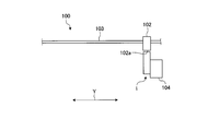
- FIG. 2 is a front view illustrating a main part of the ink jet printer including the nozzle clogging determination device according to the embodiment.
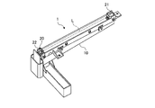
- FIG. 3 is a perspective view illustrating the nozzle clogging determination device according to the embodiment.
- FIG. 4 is another perspective view illustrating the nozzle clogging determination device according to the embodiment.
- FIG. 5 is a block diagram illustrating a configuration of an ink jet printer including the nozzle clogging determination device according to the embodiment.
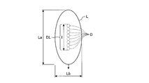
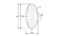
- FIG. 6 is a diagram illustrating spots of detection light received by the light receiving element of the nozzle clogging determination device according to the embodiment.
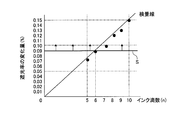
- FIG. 7 is a diagram illustrating threshold values used for determining nozzle clogging in the nozzle clogging determination apparatus according to the embodiment.
- FIG. 8A is a diagram illustrating a signal of detection light detected by the light receiving element when droplets are not ejected by the nozzle clogging determination device according to the embodiment.
- FIG. 8B is a diagram illustrating a signal of detection light detected by the light receiving element when a droplet is ejected by the nozzle clogging determination device according to the embodiment.
- FIG. 8C is a diagram obtained by amplifying only the AC component of the detection light signal shown in FIG. 8B.
- FIG. 8D is a diagram in which a pulse is generated in the detection light signal in which only the AC component shown in FIG. 8C is amplified.
- FIG. 8A is a diagram illustrating a signal of detection light detected by the light receiving element when droplets are not ejected by the nozzle clogging determination device according to the embodiment.
- FIG. 8B is
- FIG. 9 is a diagram illustrating a plurality of droplets that are continuously ejected by the nozzle clogging determination device according to the embodiment.
- FIG. 10 is an example of a flowchart at the time of determining pass / fail of the discharge state for each nozzle of the inkjet printer including the nozzle clogging determination device according to the embodiment.
- FIG. 11A is an example of a flowchart of step ST30 shown in FIG.
- FIG. 11B is an example of a flowchart of step ST34 shown in FIG. 11A.
- FIG. 12A is a diagram illustrating an outline of start mark discharge at the time of determining the quality of the discharge state for each nozzle of the inkjet printer including the nozzle clogging determination device according to the embodiment.
- FIG. 12A is a diagram illustrating an outline of start mark discharge at the time of determining the quality of the discharge state for each nozzle of the inkjet printer including the nozzle clogging determination device according to the embodiment.
- FIG. 12B is a diagram illustrating an outline of the first nozzle discharge at the time of determining the quality of the discharge state for each nozzle of the inkjet printer including the nozzle clogging determination device according to the embodiment.
- FIG. 12C is a diagram illustrating an outline of second nozzle discharge when determining whether the discharge state of each nozzle of the inkjet printer including the nozzle clogging determination apparatus according to the embodiment is good or bad.
- FIG. 12D is a diagram illustrating an outline of end mark discharge when determining whether the discharge state of each nozzle of the inkjet printer including the nozzle clogging determination apparatus according to the embodiment is good or bad.
- FIG. 12B is a diagram illustrating an outline of the first nozzle discharge at the time of determining the quality of the discharge state for each nozzle of the inkjet printer including the nozzle clogging determination device according to the embodiment.
- FIG. 12C is a diagram illustrating an outline of second nozzle discharge when determining whether the discharge state of each nozzle of the inkjet printer including
- FIG. 13 is an example of a time chart illustrating the nozzle ejection timing and the nozzle clogging determination device determination timing at the time of nozzle inspection of the inkjet printer including the nozzle clogging determination device according to the embodiment.
- FIG. 14 is another example of a time chart illustrating nozzle ejection timing and nozzle clogging determination device determination timing at the time of nozzle inspection of an inkjet printer including the nozzle clogging determination device according to the embodiment.
- FIG. 15 is a time chart showing an example of the determination result recorded in the time chart shown in FIG.
- FIG. 16 is a diagram illustrating an example in which the determination result when droplets are ejected in order from each nozzle among the continuous determination results read by the CPU is divided into equal time intervals for each nozzle.
- FIG. 17A shows a determination result when droplets are ejected in order from each nozzle among consecutive determination results read by the CPU of the nozzle clogging determination device according to the embodiment, divided into equal time intervals for each nozzle. It is a figure which shows an example of the created histogram.
- FIG. 17B is a diagram illustrating a determination result when droplets are ejected in order from each nozzle among consecutive determination results read by the CPU of the nozzle clogging determination device according to the embodiment.
- FIG. 18A is a diagram showing an example of a histogram obtained by correcting the histogram shown in FIG. 17A.
- FIG. 18B is a diagram showing a determination result when droplets are ejected in order from each nozzle in the histogram of FIG. 18A.
- FIG. 18A is a diagram showing an example of a histogram obtained by correcting the histogram shown in FIG. 17A.
- FIG. 18B is a diagram showing a determination result when droplets are ej
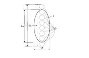
- FIG. 19 is a diagram illustrating another example of the spot of the detection light received by the light receiving element of the nozzle clogging determination device according to the embodiment.
- FIG. 20 is a diagram illustrating still another example of the spot of the detection light received by the light receiving element of the nozzle clogging determination device according to the embodiment.
- FIG. 1 is a perspective view illustrating a main part of an inkjet printer including a nozzle clogging determination device according to an embodiment.
- FIG. 2 is a front view illustrating a main part of the ink jet printer including the nozzle clogging determination device according to the embodiment.
- the nozzle clogging determination device 1 is applied to the ink jet printer 100 shown in FIG.
- the ink jet printer 100 includes a head 102 provided with a plurality of nozzles 101 (shown in FIG. 1 and the like) for discharging ink droplets D (shown in FIG. 6 and the like) supplied from an ink container (not shown) along a Y bar 103.
- the print medium is printed by reciprocating in the main scanning direction Y and ejecting ink droplets D from the nozzle 101 onto the print medium.
- the head 102 is movably supported by a Y bar 103 installed in parallel with the main scanning direction Y.
- the nozzles 101 are arranged on a straight line in the sub-scanning direction X perpendicular to the main scanning direction Y on the lower surface 102a of the head 102 facing the print medium.
- the nozzle 101 includes various ink flow paths, a regulator and a pump provided on the ink flow paths, and the like.
- Each nozzle 101 of the head 102 discharges, for example, 4 pl (picoliter) of droplets D by an inkjet method.
- the nozzle clogging determination device 1 is installed below the Y bar 103 and outside the moving range in the main scanning direction Y of the head 102 during printing, and is discharged from a plurality of nozzles 101 of the head 102.
- the nozzle 101 is clogged by detecting the passage of the ink droplet D.
- the nozzle clogging determination device 1 is adjacent to a cleaning device 104 that cleans the nozzles 101 of the head 102.
- FIG. 3 is a perspective view illustrating the nozzle clogging determination device according to the embodiment.
- FIG. 4 is another perspective view illustrating the nozzle clogging determination device according to the embodiment.
- FIG. 5 is a block diagram illustrating a configuration of an ink jet printer including the nozzle clogging determination device according to the embodiment.
- FIG. 6 is a diagram illustrating spots of detection light received by the light receiving element of the nozzle clogging determination device according to the embodiment.
- FIG. 7 is a diagram illustrating threshold values used for determining nozzle clogging in the nozzle clogging determination apparatus according to the embodiment.
- FIG. 1 is a perspective view illustrating the nozzle clogging determination device according to the embodiment.
- FIG. 4 is another perspective view illustrating the nozzle clogging determination device according to the embodiment.
- FIG. 5 is a block diagram illustrating a configuration of an ink jet printer including the nozzle clogging determination device according to the embodiment.
- FIG. 6 is a diagram illustrating spots of detection light received by
- FIG. 8A is a diagram illustrating a signal of detection light detected by the light receiving element when droplets are not ejected by the nozzle clogging determination device according to the embodiment.
- FIG. 8B is a diagram illustrating a signal of detection light detected by the light receiving element when a droplet is ejected by the nozzle clogging determination device according to the embodiment.
- FIG. 8C is a diagram obtained by amplifying only the AC component of the detection light signal shown in FIG. 8B.
- FIG. 8D is a diagram in which a pulse is generated in the detection light signal in which only the AC component shown in FIG. 8C is amplified.
- FIG. 9 is a diagram illustrating the number of droplets ejected continuously by the nozzle clogging determination device according to the embodiment.
- the nozzle clogging determination device 1 includes an ink adsorption chamber 10, a droplet detection unit 20 (shown in FIG. 4), and a determination control unit 30 (shown in FIG. 5). .
- the ink adsorption chamber 10 receives and adsorbs ink droplets D ejected from the nozzles 101 of the head 102.
- the ink adsorption chamber 10 is installed below the Y bar 103 and is formed in a box shape having an upper opening.
- the ink adsorption chamber 10 extends linearly in parallel with the sub-scanning direction X, and the ink adsorption chamber 10 is provided with a frame-shaped cover member 11 (shown in FIG. 3) at the upper end portion, so that the droplets
- the detection means 20 and the like are covered together with the cover member 11.
- the droplet detection means 20 includes a light emitting element 21 and a light receiving element 22.
- the light emitting element 21 emits detection light L for detecting the passage of the droplet D in the sub-scanning direction X that intersects the traveling direction of the droplet D ejected from each nozzle 101 of the head 102.
- the light emitting element 21 is composed of, for example, an LED (Light Emitting Diode).
- the light emitting element 21 is attached to the upper end portion of the ink adsorption chamber 10 and one end portion in the longitudinal direction of the ink adsorption chamber 10.
- the light emitting element 21 emits the detection light L toward the other end of the ink adsorption chamber 10.
- the light receiving element 22 is disposed on the opposite side across the passage of the light emitting element 21 and the droplet D and receives the detection light L emitted from the light emitting element 21. That is, the light emitting element 21, the passage of the droplet D and the light receiving element 22 are arranged along the optical path of the detection light L.
- the light receiving element 22 is composed of, for example, a PD (Photodiode).
- the light receiving element 22 is attached to the upper end portion of the ink adsorption chamber 10 and the other end portion in the longitudinal direction of the ink adsorption chamber 10.
- the droplet detection means 20 is weaker than the case where the detection light L emitted from the light emitting element 21 is blocked by the droplet D ejected from the nozzle 101 and the intensity of the detection light L received by the light receiving element 22 is not blocked. Thus, the passage of the droplet D ejected from the nozzle 101 is detected.
- the droplet detection means 20 is not provided with any optical component such as a condensing lens between the light emitting element 21 and the light receiving element 22.
- a spot (a cross-sectional shape perpendicular to the optical axis) of the detection light L emitted from the light emitting element 21 of the droplet detecting means 20 and received by the light receiving element 22 is a droplet D ejected from the nozzle 101.
- the traveling direction and the major axis are formed in an elliptical shape in parallel.
- the light receiving element 22 is disposed so that the major axis La (length in the traveling direction) of the spot of the detection light L received by the light receiving element 22 is longer than the minor diameter Lb (length in the direction intersecting the traveling direction). Has been.
- the determination control unit 30 detects from each nozzle 101 of the head 102, etc.
- a plurality of eight droplets D are continuously ejected at a time interval to form a droplet group DL (shown in FIG. 6 and the like) only once.
- the length l (shown in FIG. 6) of the traveling direction of the droplet group DL including a plurality of eight droplets D is shorter than the major axis La of the spot of the detection light L.
- the length l of the droplet group DL including the plurality of the eight droplets D is referred to as the length of the plurality of droplets D. That is, in the present invention, when nozzle clogging is detected, the determination control means 30 has a plurality of droplets D whose length l in the traveling direction is shorter from each nozzle 101 of the head 102 than the major diameter La of the detection light L. Are continuously ejected to form the droplet group DL only once.
- the determination control means 30 controls each part of the inkjet printer 100 including the nozzle clogging determination device 1.
- the determination control means 30 is configured to detect the detection light L received by the light receiving element 22 when a plurality of droplets D continuously ejected at equal time intervals are located in the spot of the detection light L received by the light receiving element 22.
- the nozzle clogging is determined based on the light shielding rate.
- the determination control means 30 has a light shielding rate (shown on the vertical axis in FIG. 7) of the detection light L received by the light receiving element 22 equal to or higher than a threshold value S (corresponding to a judgment criterion, shown in FIG. 7). In the case where the nozzle 101 is not clogged, it is determined that the nozzle 101 is clogged.
- the number of droplets D for which the light blocking rate of the detection light L is equal to or greater than the threshold value S is determined by ejecting the droplets D from the normal nozzle 101 without clogging, and the droplet group DL only once.
- the number may be any number that can exceed the threshold S when formed, and does not necessarily have to be all of the plurality of droplets D constituting the droplet group DL.
- the determination control unit 30 provides the threshold value S for determining nozzle clogging based on the light blocking rate of the detection light L received by the light receiving element 22 when the droplet D is positioned in the spot.
- the threshold value S is set to a value at which the light blocking rate of the detection light L received by the light receiving element 22 is 0.09%. That is, in this embodiment, it is determined that the nozzle 101 is not clogged when the light shielding rate is 0.09% or more, and that the nozzle 101 is clogged when it is less than 0.09%.
- the light shielding rate of 0% means a value when the detection light L emitted from the light emitting element 21 is received by the light receiving element 22 in a state where it is not blocked at all.
- the light shielding rate of 100% means that the light emitting element 21 emits light. This is a value when all of the detected light L is blocked and the light receiving element 22 cannot receive light at all.
- the horizontal axis in FIG. 7 indicates the number of droplets D when a large-dot droplet D is ejected at an ejection frequency of 14.5 KHz.
- the determination control means 30 includes an LED board 31, a control board 32, and a control means 33 as shown in FIG.
- the LED substrate 31 is attached to one end of the ink adsorption chamber 10 and has the light emitting element 21 mounted thereon. Further, the LED substrate 31 is mounted with a constant current circuit 31 a that receives a signal indicating a set light amount from a PWM circuit 40 a described later and outputs the signal to the light emitting element 21.
- the control board 32 is attached to the other end of the ink adsorption chamber 10 and has the light receiving element 22 mounted thereon.
- the control board 32 includes a light receiving amplifier 32a that amplifies a signal indicating the intensity of the detection light L received by the light receiving element 22, and a circuit 32b that detects a light receiving bias and a position from a direct current component of the signal amplified by the light receiving amplifier 32a.
- a circuit 32c is mounted which amplifies only the AC component of the signal amplified by the light receiving amplifier 32a and generates a pulse according to a threshold value S input from a CPU 41 or the like of the determination control means 30 described later.
- the intensity of the detection light L received by the light receiving element 22 after amplification by the light receiving amplifier 32a is increased.
- the signal indicating the length is constant.
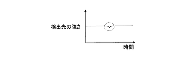
- a signal indicating the intensity of the detection light L received by the light receiving element 22 is output after the amplification by the light receiving amplifier 32a as shown in FIG. 8B. Is slightly weakened when it is positioned at the spot of the detection light L (indicated by a dotted line in FIG. 8B).
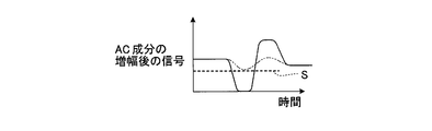
- the circuit 32c amplifies only the AC component (portion surrounded by a dotted line in FIG. 8B) of the signal indicating the intensity of the detection light L as shown in FIG. 8C. When the amplified AC component exceeds the threshold value S, the circuit 32c generates a pulse as shown in FIG. 8D.
- the generated pulse indicates that the light blocking rate of the detection light L received by the light receiving element 22 is equal to or greater than the threshold value S, that is, it is determined that the nozzle 101 is not clogged. . That is, in this embodiment, “0” on the vertical axis in FIG. 8D indicates that the nozzle 101 is determined not to be clogged, and “1” on the vertical axis in FIG. 8D indicates that the nozzle 101 is clogged. Indicates that it has been determined.
- the circuit 32c generates a determination result (shown in FIG. 8D) indicating nozzle clogging.
- the pulse width at this time is preferably in the range of 300 ⁇ sec to 500 ⁇ sec. If it is less than 300 ⁇ sec, it is difficult to distinguish between a pulse and noise.
- the detection range from the next nozzle 101 is affected, and the droplet detection means 20 cannot perform accurate detection. Further, from the relationship with the number of droplets D when a large dot droplet D is ejected at an ejection frequency of 14.5 KHz shown in FIG. It is desirable that the number be at least one and not more than nine. In the present embodiment, the number is eight.
- Control means 33 controls each part of inkjet printer 100.
- the control unit 33 includes an integrated circuit unit 40, a CPU 41, and the like.
- the CPU 41 outputs a signal indicating the set light amount of the light emitting element 21 and a signal indicating the threshold value S to the integrated circuit unit 40. Further, the CPU 41 receives a signal indicating the light receiving bias of the detection light L received by the light receiving element 22, the position of the received detection light L, and the determination result of the circuit 32c.
- the integrated circuit unit 40 includes a PWM circuit 40a to which a signal indicating a set light amount and a signal indicating a threshold S are input from the CPU 41, an A / D converter 40b, a memory 40c, and the like.
- the PWM circuit 40 a outputs a signal indicating the set light amount to the constant current circuit 31 a of the LED substrate 31.
- the PWM circuit 40a outputs a signal indicating the threshold value S to the circuits 32b and 32c.
- the A / D converter 40b converts the light reception bias and the signal indicating the position of the detection light L input from the circuit 32b into digital signals, and then outputs them to the CPU 41.
- the memory 40c receives the nozzle clogging determination result from the circuit 32c via the buffer 40d, temporarily stores it, and then outputs it to the CPU 41.
- FIG. 10 is an example of a flowchart at the time of determining pass / fail of the discharge state for each nozzle of the inkjet printer including the nozzle clogging determination device according to the embodiment.
- FIG. 11A is an example of a flowchart of step ST30 shown in FIG. FIG.
- FIG. 11B is an example of a flowchart of step ST34 shown in FIG. 11A.
- FIG. 12A is a diagram illustrating an outline of start mark discharge at the time of determining the quality of the discharge state for each nozzle of the inkjet printer including the nozzle clogging determination device according to the embodiment.
- FIG. 12B is a diagram illustrating an outline of the first nozzle discharge at the time of determining the quality of the discharge state for each nozzle of the inkjet printer including the nozzle clogging determination device according to the embodiment.
- FIG. 12C is a diagram illustrating an outline of second nozzle discharge when determining whether the discharge state of each nozzle of the inkjet printer including the nozzle clogging determination apparatus according to the embodiment is good or bad.
- FIG. 12A is a diagram illustrating an outline of start mark discharge at the time of determining the quality of the discharge state for each nozzle of the inkjet printer including the nozzle clogging determination device according to the embodiment.
- FIG. 12B is a diagram illustrating
- 12D is a diagram illustrating an outline of end mark discharge when determining whether the discharge state of each nozzle of the inkjet printer including the nozzle clogging determination apparatus according to the embodiment is good or bad. It should be noted that the determination control means 30 executes the determination of nozzle clogging of the ink droplet D from each nozzle 101 and the determination of the quality of the discharge state for each nozzle 101 as nozzle inspection.
- the determination control means 30 emits the detection light L from the light emitting element 21 without ejecting ink from the nozzle 101 of the nozzle clogging determination apparatus 1 to receive the light receiving element 22.
- the amount of the detection light L from the light emitting element 21 is adjusted by receiving the light (step ST10).
- the position of the droplets D ejected from the nozzles 101 is moved by moving the head 102 above the nozzle clogging determination device 1 and ejecting the ink droplets D from all the nozzles 101 at the same time. May be detected.
- the determination control means 30 determines whether a nozzle test is performed (step ST20).
- the determination control means 30 repeats step ST20 when determining that the nozzle inspection is not executed (step ST20: No), and executes the nozzle inspection when it is determined that the nozzle inspection is executed (step ST20: Yes) (step ST30). ).
- the determination control unit 30 corresponds to, for example, immediately after the inkjet printer 100 is turned on, at the start of printing of the inkjet printer 100, or when a command for executing nozzle inspection is received from an operation panel (not shown) or the like. Perform nozzle inspection. The nozzle inspection method will be described in detail later.
- the determination control means 30 determines whether or not there is a defective nozzle 101 in the ejection state of the ink droplet D among the plurality of nozzles 101, that is, whether or not there is a missing nozzle (step ST40). If the determination control means 30 determines that there is no defective nozzle 101 in the ejection state of the ink droplets D among the plurality of nozzles 101, that is, that there is no missing nozzle (step ST40: No), the ink jet printer 100 is determined. The standby state is set (step ST80).
- step ST40 determines that there is a defective nozzle 101 in the ejection state of the ink droplets D among the plurality of nozzles 101, that is, if there is a missing nozzle (step ST40: Yes), there is a missing nozzle.
- the number of times determined to be increased is recorded once, and it is determined whether or not the recorded number is equal to or less than a predetermined number (step ST50). If the determination control means 30 determines that the number is less than or equal to the predetermined number of times (step ST50: Yes), the cleaning device 104 cleans each nozzle 101 of the head 102 (step ST60) and returns to step ST30.
- step ST50 determines that it is not less than the predetermined number of times (step ST50: No)
- step ST70 displays that there is a nozzle missing or the like on the display screen of the operation panel
- step ST80 puts the inkjet printer 100 in a standby state
- step ST80 the determination control means 30 resets the number of times determined that there is a missing nozzle in step ST40 to zero.
- FIG. 13 is an example of a time chart illustrating the nozzle ejection timing and the nozzle clogging determination device determination timing at the time of nozzle inspection of the inkjet printer including the nozzle clogging determination device according to the embodiment.
- FIG. 14 is another example of a time chart illustrating nozzle ejection timing and nozzle clogging determination device determination timing at the time of nozzle inspection of an inkjet printer including the nozzle clogging determination device according to the embodiment.
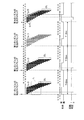
- FIG. 15 is a time chart showing an example of the determination result recorded in the time chart shown in FIG.
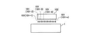
- the determination control means 30 causes each part of the ink jet printer 100 and the nozzle clogging determination device 1 to start a nozzle inspection, and starts recording the determination result of the circuit 32c (step ST31). Specifically, the determination control unit 30 passes the ink droplet D discharged from the nozzle 101 through the head 102 above the nozzle clogging determination device 1 and in the spot of the detection light L received by the light receiving element 22. Position it at the position you want. Then, as shown in FIG. 12A, the determination control unit 30 discharges the droplets D from all the nozzles 101 continuously for a predetermined time.
- the determination control means 30 After finishing the ejection of the droplets D from all the nozzles 101, the determination control means 30 sequentially sets the eight as a plurality at equal time intervals for each predetermined time T (shown in FIG. 13) from each nozzle 101 of the head 102. The droplets D are discharged continuously.
- the determination control unit 30 continuously supplies eight droplets D from the first nozzle 101-1 located at one end in the sub-scanning direction X among the plurality of nozzles 101 at equal time intervals.
- FIG. 12C as shown in FIG. 12C, after a predetermined time T from the start of discharging the droplet D from the first nozzle 101-1, the second nozzle is closer to the other end in the sub-scanning direction X.
- the eight droplets D are continuously ejected from the second nozzle 101-2 at regular time intervals.
- the determination control unit 30 continuously discharges eight droplets D at equal time intervals from each nozzle 101 up to the Nth nozzle 101-n.
- the determination control means 30 sequentially discharges eight droplets D from the nozzles 101 in order at equal time intervals up to the Nth nozzle 101-n, and then continuously drops from all the nozzles 101 for a predetermined time. D is discharged.
- the determination control unit 30 sequentially discharges eight droplets D from the nozzles 101 of the head 102 at regular time intervals at predetermined time intervals, and discharges the droplets D from the nozzles 101 in order. Droplets D are continuously ejected from all the nozzles 101 of the head 102 both before and after. In the present invention, the determination control means 30 continues the droplets D from all the nozzles 101 of the head 102 at least one of before and after the droplets D are sequentially discharged from each nozzle 101. May be discharged.
- the droplet detection means 20 Detects the droplet D passing through the spot of the detection light L, and the circuit 32c determines whether the nozzle of the droplet D is clogged.
- the upper part of FIG. 13 shows the discharge timing from the nozzle 101 of the head 102, and the lower part of FIG. 13 shows the liquid in the circuit 32c when it is normally discharged from the nozzle 101 at the timing shown in FIG. The timing for determining the nozzle clogging of the droplet D is shown.
- the time from the start of the discharge of the droplets D from all the nozzles 101 to the start of the discharge from the first nozzle 101 is set to 12 msec, and the second discharge from the start of the first nozzle 101-1.
- the predetermined time T until the start of discharge from the nozzle 101-2 is 2 msec. That is, the time interval between the start of ejection from the nozzle 101 is set to 2 msec which is the predetermined time T.
- the time from the start of discharge of the Nth nozzle 101-n to the start of discharge from all the nozzles 101 is set to 12 msec.
- the droplets D are ejected at equal time intervals with a frequency of 14.5 KHz, and the droplets D from each nozzle 101 are discharged. Is set to 552 ⁇ sec.
- the circuit 32c determines that the nozzles are not clogged after the start of ejection from each nozzle 101, as shown in the lower part of FIG.
- the time for the circuit 32c to determine that the nozzle is not clogged is slightly shorter than the time for continuously ejecting eight droplets D from each nozzle 101.
- the determination control unit 30 detects the detection result of the droplet detection unit 20 when the droplets D are continuously discharged from the nozzles 101 at regular time intervals and when the droplets D are discharged from all the nozzles 101. Based on the above, nozzle clogging is determined and recorded continuously at a fixed minute time t (shown in FIG. 15). Specifically, as shown in FIG. 15).
- the determination control unit 30 first discharges the droplets D sequentially from each nozzle 101 from the start of discharging the droplets D from all the nozzles 101, Finally, until the discharge of the droplets D from all the nozzles 101 is completed, the light reception result of the light receiving element 22 of the droplet detection means 20 is determined by the circuit 32c, and the circuit is detected every 20 ⁇ sec, which is a fixed minute time t. The determination result of 32c is continuously recorded in the memory 40c.
- the determination control means 30 first determines the determination result of the circuit 32c from the start of discharge of the droplets D from all the nozzles 101 until the end of discharge of the droplets D from all the nozzles 101 at the end, that is, the nozzles “0” when there is no clogging and “1” when the nozzle is clogged are recorded every 20 ⁇ sec which is a fixed minute time t.
- the determination control means 30 temporarily stores the determination result every 20 ⁇ sec, which is a fixed minute time t of the circuit 32c, in the buffer 40d and then continuously records it in the memory 40c.
- FIG. 14 shows the ejection timing from each nozzle 101 of the head 102, the eight droplets D ejected and the spot of the detection light L received by the light receiving element 22, and the middle part of FIG.
- the discharge timing from the nozzle 101 of 102 is shown, and the lower part of FIG. 14 shows an example of the determination result of the circuit 32c.
- the droplets D that are normally ejected are indicated by black circles, and the droplets D that are not ejected are indicated by white circles.
- FIG. 14 shows that eight droplets D are normally discharged from the first nozzle 101-1 and the second nozzle 101-2 in succession, and none of the third nozzle 101-3 is discharged.
- the droplet D cannot be discharged
- the first six droplets D are continuously discharged from the fourth nozzle 101-4
- the last two droplets D cannot be discharged.
- the third nozzle 101 -3 indicates that there is no time at which the nozzle is determined to be clogged, and the time at which the nozzle from the fourth nozzle 101-4 is determined to be free of clogging is the first nozzle 101-1 and the first nozzle 101-1. It is shown that it is shorter than the second nozzle 101-2.
- the determination control unit 30 first starts discharging the droplets D from all the nozzles 101 and then sequentially discharges the droplets D from all the nozzles 101 until the end of discharging the droplets D from all the nozzles 101. In the meantime, it is determined whether or not the recording result of the circuit 32c is continuously recorded in the memory 40c every certain minute time t (step ST32). If the determination control means 30 determines that recording of the determination result has not been completed (step ST32: No), step ST32 is repeated. When the determination control means 30 determines that recording of the determination result is completed (step ST32: Yes), the CPU 41 reads the continuous determination result recorded in the memory 40c (step ST33) and analyzes the read determination result. (Step ST34).
- the determination result read at this time is a fixed minute time t such as 20 ⁇ sec from the start of the discharge of the droplets D from all the nozzles 101 to the end of the discharge of the droplets D from all the nozzles 101 at the end. It is composed of “0” and “1” which are the determination results of each circuit 32c.
- the upper part of FIG. 15 shows the ejection timing from each nozzle 101 of the head 102, the middle part of FIG. 15 shows an example of the determination result of the circuit 32c, and the lower part of FIG. An example of the result is shown.
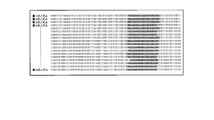
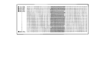
- FIG. 16 is a diagram illustrating an example in which the determination result when droplets are ejected in order from each nozzle among the continuous determination results read by the CPU 41 is divided into equal time intervals for each nozzle.
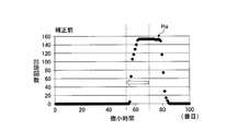
- FIG. 17A shows a determination result when droplets are ejected in order from each nozzle among consecutive determination results read by the CPU of the nozzle clogging determination device according to the embodiment, divided into equal time intervals for each nozzle. It is a figure which shows an example of the created histogram.
- FIG. 16 is a diagram illustrating an example in which the determination result when droplets are ejected in order from each nozzle among the continuous determination results read by the CPU 41 is divided into equal time intervals for each nozzle.
- FIG. 17A shows a determination result when droplets are ejected in order from each nozzle among consecutive determination results read by the CPU of the nozzle clogging determination device according to the embodiment, divided into equal time intervals for each nozzle. It is a figure which shows an example of the created histogram.
- FIG. 17B is a diagram illustrating a determination result when droplets are ejected in order from each nozzle among consecutive determination results read by the CPU of the nozzle clogging determination device according to the embodiment.
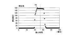
- FIG. 18A is a diagram showing an example of a histogram obtained by correcting the histogram shown in FIG. 17A.
- FIG. 18B is a diagram showing a determination result when droplets are ejected in order from each nozzle in the histogram of FIG. 18A.
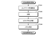
- the determination control means 30 when analyzing the determination result, the determination control means 30 finally determines the nozzle clogging determination result E when the droplets D are continuously discharged from all the nozzles 101 from the continuous determination result read by the CPU 41. (Shown in FIG. 15) is detected (step ST341).
- the determination result of nozzle clogging when the droplets D are first ejected from all the nozzles 101 may be detected.
- the nozzle clogging determination result E when the droplets D are finally discharged from all the nozzles 101 is detected more when the droplet D is discharged last than when the droplet D is discharged first. This is because it is considered that the droplet D is ejected from the nozzle 101.
- the determination control means 30 uses the determination result E of nozzle clogging when the droplets D are finally discharged from all the nozzles 101 as a reference, and sequentially determines the droplets D from the nozzles 101 among the determination results continuously recorded.
- the determination result when continuously ejected is divided into equal time (predetermined time T) intervals for each nozzle 101 (step ST342).
- the determination result of “0” or “1” of the circuit 32c is recorded every 20 ⁇ sec, and 12 msec has elapsed from the start of discharge from the Nth nozzle 101-n to the start of discharge from all the nozzles 101 at the end. is doing. For this reason, in the continuous determination result of the circuit 32c, the detection results of the 600 circuits 32c and the discharge results from all the nozzles 101 until the last discharge start from all the nozzles 101-n There is a minute time t. In addition, since the discharge start time interval between the nozzles 101 (corresponding to the predetermined time T) is 2 msec, the determination result of the 100 circuits 32c and the minute time t exist between the discharge start of the nozzles 101. ing.
- the determination control means 30 determines, for example, from the end of the determination results within the minute time t of the 600 circuits 32c from the start of discharge from the Nth nozzle 101-n to the end of discharge from all the nozzles 101. From the determination result in the 541st minute time t toward the determination result of the first nozzle 101-1, droplets D are successively discharged from each nozzle 101 in order for every determination result in 100 minute times t. Then, the determination results recorded continuously are divided. That is, as shown in FIG. 17B, when the droplets D are sequentially ejected from the respective nozzles 101, the portion determined as “0” is located in the center and the portion determined as “1” Each nozzle 101 is divided so as to be positioned at both ends.
- the determination control unit 30 divides the determination result when the droplets D are continuously discharged from each nozzle 101 in order into each nozzle 101 at equal time (predetermined time T) intervals.
- a nozzle indicating the number of appearances of the minute time t determined to have no clogging for the determination result nozzle divided into two is created, and the nozzle having the highest number of appearances has the minute time t determined to be clogged at the center. It correct
- the determination control means 30 is the 100th determination result from the determination result within the first minute time t of the determination results of the circuit 32c within 100 minute times t divided for each nozzle 101 in step ST342.
- the number of appearances that the nozzles are not clogged is calculated in the order of the determination results within the minute time t.
- the determination results of the circuit 32c within 100 minute times t divided for each nozzle 101 in step ST342 are the first to Nth nozzles 101-n.
- the number of appearances of the nozzles within the first minute time t of the arranged determination results that are not clogged are determined,
- the number of occurrences of no clogging of the nozzles in each of the first minute times t up to the 100th is obtained in order.
- the minute time t is plotted on the horizontal axis (the first minute time t is shown at the left end in the figure and the 100th minute time t is shown at the right end in the figure).
- a histogram Ha is created with the vertical axis representing the sum of the number of times that the nozzle is determined not to be clogged within the minute time t (the number of appearances of the minute time t determined to be that the nozzle is not clogged). That is, the vertical axis of FIG. 17A is divided for each nozzle 101 in the state shown in FIG. 17B, and is the minute time t determined as “0” as the determination result of the circuit 32c within 100 minute times t. The value obtained by adding the number in the vertical direction of FIG. 17B is shown.
- the determination control means 30 obtains the second minute time t (indicated by a two-dot chain line in FIG. 17A) at which it is determined that the nozzle having the highest number of appearances is not clogged.
- the nozzle is regarded as the second minute time t.
- the nozzle is set to the second minute time t located at the center of these minute times t.
- droplets D are sequentially applied from the respective nozzles 101 in the determination results continuously recorded so that the minute time t having the largest number of appearances indicated by a two-dot chain line in FIG. 17A is located at the center of the histogram Ha.
- the position where the determination result at the time of ejection is divided for each nozzle 101 is corrected. Specifically, the minute time t between the most frequently appearing time indicated by a two-dot chain line in FIG. 17A and the center of the horizontal axis in FIG. 17A of the histogram Ha (indicated by the one-dot chain line in FIG. 17A).
- the number of times t is obtained, and this number is shifted in position when divided in step ST342.
- the determination control means 30 Among the 600 minute times t from the start of discharge from the Nth nozzle 101-n to the last start of discharge from all the nozzles 101, the first nozzle 101 starts from the last 541 + Ath minute time t, for example. Dividing every 100 minute times t toward the determination result. In this way, the determination control means 30 obtains the determination result divided for each nozzle 101 and the histogram Hb shown in FIG. 18A, as shown in FIGS. 16 and 18B.
- the minute time t when the nozzle is determined to be clogged is indicated by a white background
- the minute time t when the nozzle is determined not to be clogged is indicated by a black background. Show.
- the determination control means 30 determines the quality of the discharge state for each nozzle 101 based on the determination result divided for each nozzle 101 shown in FIG. 16 (step ST344).
- eight droplets D are discharged from each nozzle 101 during 552 ⁇ sec, and “0” or “1”, which is the determination result of the circuit 32c, is recorded every 20 ⁇ sec. Is discharged, a determination result within a minute time t determined to be less than 20 “0” is obtained at the center of the determination result divided for each nozzle 101.
- the determination control means 30 determines that the nozzles are not clogged, that is, if the number of minute times t determined as “0” is equal to or greater than a predetermined number, When it is determined that the discharge state is good and the number of minute times t determined as “0” is less than a predetermined number, it is determined that the discharge state from each nozzle 101 is defective. In the present embodiment shown in FIG. 16, the determination control unit 30 determines that the discharge state from the third nozzle 101-3 and the fourth nozzle 101-4 is defective, and outputs from the other nozzles 101. It is determined that the discharge state is good. Thus, the determination control means 30 ends the analysis of the read determination result.
- the nozzle clogging determination device 1 positions a plurality of droplets D continuously ejected at equal time intervals within the spot of the detection light L received by the light receiving element 22, so that the cost increases. Even if a lens for narrowing the detection light L is not provided, the intensity of the detection light received by the light receiving element 22 when the droplet D blocks the detection light L, and when the droplet D does not block the detection light L, the light is received. A difference from the intensity of the detection light received by the element 22 can be generated. For this reason, the nozzle clogging determination device 1 can improve the s / n ratio of the light receiving element 22 even when the droplet D becomes smaller.
- the nozzle clogging determination device 1 since the nozzle clogging determination device 1 does not need to squeeze the detection light L, even if the relative position between the head 102 having the nozzle 101 and the nozzle clogging determination device 1 is shifted, the ink discharged from the head 102 is discharged.
- the liquid droplet D can be passed through the detection light L, and ink nozzle clogging can be reliably detected. Therefore, the nozzle clogging determination device 1 can detect the nozzle clogging of the droplet D without causing an increase in cost.
- the nozzle clogging determination device 1 has a threshold value S for determining nozzle clogging when a plurality of droplets D continuously ejected from the nozzle 101 of the head 102 at regular intervals are positioned in the spot. For this reason, the nozzle clogging determination device 1 can reliably detect ink clogging even if the relative position between the head 102 having the nozzle 101 and the nozzle clogging determination device 1 is shifted. Therefore, it is possible to determine the nozzle clogging of the nozzle 101 without erroneous detection, without having to discharge the ink droplets D in a plurality of times. Therefore, the nozzle clogging determination device 1 can prevent the detection time from being prolonged.
- the determination control means provides a determination criterion for determining nozzle clogging when a plurality of continuously ejected liquid droplets from the head nozzle are positioned in the spot. Nozzle clogging can be determined without discharging continuously and repeatedly.
- the nozzle clogging determination device 1 determines nozzle clogging based on the light blocking rate of the detection light L received by the light receiving element 22, it can reliably determine nozzle clogging. Moreover, since the major axis La parallel to the traveling direction of the spot of the detection light L received by the light receiving element 22 is longer than the minor axis Lb, the nozzle clogging determination device 1 is continuously arranged at equal time intervals in the spot. All of the discharged droplets D can be positioned. Therefore, the nozzle clogging determination device 1 detects the intensity of the detection light L received by the light receiving element 22 when the liquid droplet D blocks the detection light L and the liquid droplet D even if the number of liquid droplets D is minimized. A difference from the intensity of the detection light L received by the light receiving element 22 when the light L is not blocked can be generated.
- the nozzle clogging determination device 1 sequentially discharges a plurality of droplets D at regular time intervals from the nozzles 101 at predetermined time intervals in order, and at least one before and after sequentially discharging from the nozzles 101 in sequence.
- droplets D are continuously ejected from all the nozzles 101, and nozzle clogging is determined and recorded continuously at a constant minute time t based on the detection result of the droplet detection means 20. For this reason, the nozzle clogging determination device 1 determines the determination result when the ink droplets D are ejected from all the nozzles 101 and the nozzle clogging when the droplets D are sequentially ejected from each nozzle 101 in sequence.
- the determination result can be obtained in a time series.
- the nozzle clogging determination apparatus 1 can quickly acquire the determination results because the determination results are arranged in time series, and can suppress the determination time from being lengthened. Further, the nozzle clogging determination device 1 can easily identify the determination results between the nozzles 101 by using the determination results when the ink droplets D are discharged from all the nozzles 101 as a reference. It is possible to reliably grasp nozzle clogging when droplets D are continuously discharged from each nozzle 101.
- the nozzle clogging determination device 1 uses the determination result when the ink droplets D are discharged from all the nozzles 101 as a reference, and the determination result when the droplets D are sequentially discharged from the nozzles 101 in order.
- Each nozzle 101 is divided into equal time (predetermined time T) intervals. For this reason, in the nozzle clogging determination device 1, each determination result divided at equal time intervals includes the determination result of nozzle clogging when droplets D are continuously discharged from each nozzle 101. Therefore, the nozzle clogging determination device 1 can reliably grasp the nozzle clogging of the droplet D from each nozzle 101.
- the nozzle clogging determination device 1 creates a histogram, and the droplets D are successively applied from the nozzles 101 in order so that the minute time t when it is determined that the nozzle with the highest number of appearances is not clogged is positioned at the center. Then, the division of the determination result when discharging is corrected. For this reason, the nozzle clogging determination device 1 surely includes the determination result when ink is ejected from each nozzle 101 in each determination result divided at equal time intervals.
- the nozzle clogging determination device 1 determines the quality of the discharge state of each nozzle 101 based on the number of minute times t in which it is determined that the nozzle is not clogged in each determination result divided at equal time intervals. To do. For this reason, the nozzle clogging determination device 1 does not determine the quality of the discharge state of each nozzle 101 based on the determination result of a small number of minute times t. This can be suppressed.
- the nozzle clogging determination device 1 increases the amount of ink that constitutes the droplet D, and determines the length l of the plurality of droplets D as the detection light L. It may be substantially equal to the major axis La of the spot. As shown in FIG. 20, the nozzle clogging determination device 1 increases the amount of ink constituting the droplet D, and sets the length l of the plurality of droplets D to be larger than the major axis La of the spot of the detection light L. It may be longer.
- FIG. 19 is a diagram illustrating another example of a spot of detection light received by the light receiving element of the nozzle clogging determination apparatus according to the embodiment, and FIG.
- FIGS. 19 and 20 are a light receiving element of the nozzle clogging determination apparatus according to the embodiment. It is a figure which shows the further another example of the spot of the detection light which light-receives. As shown in FIGS. 19 and 20, when the length l of the plurality of droplets D is substantially equal to the major axis La of the spot of the detection light L, or longer than the major axis La of the spot of the detection light L, In a state in which a plurality of droplets D are ejected continuously, the time during which the light shielding rate of the detection light received by the light receiving element 22 is equal to or greater than the threshold value S is increased, so that accurate detection can be performed. .
- each nozzle 101 of the head 102 it is not necessary to discharge the droplets D from each nozzle 101 of the head 102 at equal time intervals, and it is only necessary that each nozzle 101 has at least one determination result determined by at least the threshold value S. In short, in the present invention, it is sufficient that at least one droplet D is ejected from each nozzle 101 of the head 102 and the determination result determined by the threshold value S is provided at least once.
Landscapes
- Ink Jet (AREA)
Abstract
Description
以下に、本発明の実施形態に係るノズルの詰まり判定装置を図面に基いて詳細に説明する。図1は、実施形態に係るノズルの詰まり判定装置を備えたインクジェットプリンタの要部を表す斜視図である。図2は、実施形態に係るノズルの詰まり判定装置を備えたインクジェットプリンタの要部を表す正面図である。
20 液滴検出手段
21 発光素子
22 受光素子
30 判定制御手段
100 インクジェットプリンタ
101 ノズル
102 ヘッド
D 液滴
DL 液滴群
E 判定結果
L 検出光
T 所定時間
t 微小時間
Ha,Hb ヒストグラム
S 閾値(判定基準)
Claims (6)
- インクジェットプリンタのヘッドのノズルから吐出される複数の液滴の通過を検出して前記ノズルの詰まりを判定するノズルの詰まり判定装置において、
前記液滴の進行方向に交差する方向に前記液滴の通過を検出するための検出光を出射する発光素子と、前記検出光を受光する受光素子と、を備え、前記発光素子と前記液滴の通過通路と前記受光素子とが前記検出光の光路に沿って配設される液滴検出手段と、
前記ヘッドのノズルから複数の液滴を吐出させ、前記受光素子が受光した前記検出光のスポット内に前記液滴が位置したときの前記受光素子が受光した検出光の遮光率によりノズル詰まりを判定する判定基準を設けた判定制御手段と、
を備えることを特徴とするノズルの詰まり判定装置。 - 前記判定制御手段は、
前記受光素子が受光した検出光の遮光率が、所定の遮光率以上の場合前記ノズルは詰まりが無いと判定し、前記所定の遮光率未満の場合前記ノズルは詰まりがあると判定する、
ことを特徴とする請求項1に記載のノズルの詰まり判定装置。 - 前記受光素子が受光した前記検出光のスポットの前記進行方向の長さが前記進行方向に交差する方向の長さよりも長くなるように、前記受光素子が配設されていることを特徴とする請求項1に記載のノズルの詰まり判定装置。
- 前記判定制御手段は、
前記ヘッドの各ノズルから順に等間隔で複数の液滴を連続して吐出させ、
かつ、各ノズルから順に前記液滴を連続して吐出させる前後のうちの少なくとも一方において、前記ヘッドの全てのノズルから液滴を連続して吐出させるとともに、
前記各ノズルから順に前記液滴を連続して吐出した際及び前記全てのノズルから液滴を吐出した際の前記液滴検出手段の検出結果に基いて一定の微小時間毎にノズル詰まりを判定して連続して記録し、その後、全てのノズルから液滴を吐出した際のノズル詰まりの判定結果を基準に、連続して記録した判定結果のうちの前記各ノズルから順に前記液滴を連続して吐出した際の判定結果を各ノズル毎に等時間間隔に分割して、各ノズル毎の吐出状態の良否を判定する
ことを特徴とする請求項1から請求項3のうちいずれか一項に記載のノズルの詰まり判定装置。 - 前記判定制御手段は、
前記各ノズルから順に前記液滴を連続して吐出した際の判定結果を各ノズル毎に等時間間隔に分割する際に、各ノズル毎に分割された判定結果のノズルは詰まりが無いと判定された前記微小時間の出現回数を示すヒストグラムを作成して、最も出現回数の多いノズルは詰まりが無いと判定された微小時間が中央となるように補正する
ことを特徴とする請求項4に記載のノズルの詰まり判定装置。 - 前記判定制御手段は、
各ノズル毎の吐出状態の良否を判定する際に、
各ノズル毎に分割された判定結果において前記ノズルは詰まりが無いと判定された微小時間が所定数以上であると吐出状態が良好であると判定し、
各ノズル毎に分割された判定結果において前記ノズルは詰まりが無いと判定された微小時間が所定数未満であると吐出状態が不良であると判定する
ことを特徴とする請求項4に記載のノズルの詰まり判定装置。
Priority Applications (4)
| Application Number | Priority Date | Filing Date | Title |
|---|---|---|---|
| CN201580025267.9A CN106457820B (zh) | 2014-05-16 | 2015-05-15 | 喷嘴堵塞判定装置 |
| US15/310,437 US10124578B2 (en) | 2014-05-16 | 2015-05-15 | Nozzle-clogging determining device |
| EP15792167.7A EP3144149B1 (en) | 2014-05-16 | 2015-05-15 | Nozzle clog diagnosis device |
| JP2016519416A JP6517194B2 (ja) | 2014-05-16 | 2015-05-15 | ノズルの詰まり判定装置 |
Applications Claiming Priority (2)
| Application Number | Priority Date | Filing Date | Title |
|---|---|---|---|
| JP2014102904 | 2014-05-16 | ||
| JP2014-102904 | 2014-05-16 |
Publications (1)
| Publication Number | Publication Date |
|---|---|
| WO2015174536A1 true WO2015174536A1 (ja) | 2015-11-19 |
Family
ID=54480071
Family Applications (1)
| Application Number | Title | Priority Date | Filing Date |
|---|---|---|---|
| PCT/JP2015/064116 Ceased WO2015174536A1 (ja) | 2014-05-16 | 2015-05-15 | ノズルの詰まり判定装置 |
Country Status (5)
| Country | Link |
|---|---|
| US (1) | US10124578B2 (ja) |
| EP (1) | EP3144149B1 (ja) |
| JP (1) | JP6517194B2 (ja) |
| CN (1) | CN106457820B (ja) |
| WO (1) | WO2015174536A1 (ja) |
Cited By (1)
| Publication number | Priority date | Publication date | Assignee | Title |
|---|---|---|---|---|
| JP2019144139A (ja) * | 2018-02-21 | 2019-08-29 | 株式会社リコー | 検査装置、情報処理装置、及びプログラム |
Families Citing this family (12)
| Publication number | Priority date | Publication date | Assignee | Title |
|---|---|---|---|---|
| JP2017136787A (ja) * | 2016-02-05 | 2017-08-10 | セイコーエプソン株式会社 | 液滴吐出装置及び液滴吐出装置における液体使用量の算出方法 |
| TWI671125B (zh) * | 2017-09-13 | 2019-09-11 | 心誠鎂行動醫電股份有限公司 | 霧化器 |
| JP7302212B2 (ja) * | 2019-03-19 | 2023-07-04 | コニカミノルタ株式会社 | 吐出状態検出装置、吐出状態検出方法およびインクジェット記録装置 |
| CN110370802A (zh) * | 2019-07-29 | 2019-10-25 | 深圳市华星光电半导体显示技术有限公司 | 喷墨打印设备及其调节方法 |
| CN110341320B (zh) * | 2019-08-27 | 2024-07-12 | 高铭科维科技无锡有限公司 | 纳维码自动打印装置 |
| KR20220054502A (ko) * | 2020-10-23 | 2022-05-03 | 삼성디스플레이 주식회사 | 표시 장치의 제조장치 및 표시 장치의 제조방법 |
| CN115342852A (zh) * | 2022-08-15 | 2022-11-15 | 中国铁建重工集团股份有限公司 | 一种堵塞检测方法、装置及分离设备 |
| US12459264B2 (en) | 2023-03-03 | 2025-11-04 | Ricoh Company, Ltd. | Printhead maintenance for recommending printhead replacement |
| KR20250085138A (ko) | 2023-12-05 | 2025-06-12 | 주식회사 엘지에너지솔루션 | 배터리 충전 방법 및 이를 이용하는 배터리 관리 장치 |
| CN118218175B (zh) * | 2024-05-22 | 2024-07-12 | 甘肃百优雄关新型建材有限公司 | 一种架空地板防静电烤漆喷涂设备 |
| CN118769723B (zh) * | 2024-07-12 | 2025-09-09 | 贵州劲嘉新型包装材料有限公司 | 一种带有喷头保护及清洁装置的数码喷印设备 |
| CN120607051B (zh) * | 2025-07-08 | 2025-10-28 | 北京派通电力设备有限责任公司 | 一种基于多源感知与最优控制的落煤管智能防堵控制方法 |
Citations (5)
| Publication number | Priority date | Publication date | Assignee | Title |
|---|---|---|---|---|
| JP2003225996A (ja) * | 2001-11-30 | 2003-08-12 | Konica Corp | 微小液滴の検出装置及びインクジェット記録装置 |
| JP2006007447A (ja) * | 2004-06-22 | 2006-01-12 | Konica Minolta Holdings Inc | インクジェット記録装置及び吐出不良ノズルの検出方法 |
| JP2006044000A (ja) * | 2004-08-03 | 2006-02-16 | Sharp Corp | 液滴の吐出状態検出方法 |
| JP2006168194A (ja) * | 2004-12-16 | 2006-06-29 | Canon Inc | インクジェット記録装置 |
| JP2013180525A (ja) * | 2012-03-02 | 2013-09-12 | Ricoh Co Ltd | 画像形成装置 |
Family Cites Families (16)
| Publication number | Priority date | Publication date | Assignee | Title |
|---|---|---|---|---|
| DE69931134T2 (de) | 1999-02-12 | 2007-04-19 | Hewlett-Packard Development Company, L.P., Houston | Verfahren zur Tintentropfenerfassung in einem Druckgerät |
| JP2001113725A (ja) * | 1999-10-15 | 2001-04-24 | Canon Inc | インクジェットプリンタ装置 |
| US6692099B2 (en) * | 2001-04-30 | 2004-02-17 | Hewlett-Packard Development Company, L.P. | Testing nozzles in print heads |
| JP3815257B2 (ja) * | 2001-05-30 | 2006-08-30 | セイコーエプソン株式会社 | ドット抜け検査を行う印刷 |
| US6648444B2 (en) * | 2001-11-15 | 2003-11-18 | Hewlett-Packard Development Company, L.P. | High throughput parallel drop detection scheme |
| JP3858680B2 (ja) | 2001-11-30 | 2006-12-20 | コニカミノルタホールディングス株式会社 | 微小液滴の通過検出装置及びインクジェット記録装置 |
| JPWO2004011262A1 (ja) * | 2002-07-25 | 2005-11-24 | セイコーエプソン株式会社 | 液体吐出装置、及び、印刷システム |
| JP2004207485A (ja) * | 2002-12-25 | 2004-07-22 | Seiko Epson Corp | ノズル詰まり検出装置、液滴吐出装置、電気光学装置、電気光学装置の製造方法及び電子機器 |
| JP2004314533A (ja) * | 2003-04-18 | 2004-11-11 | Seiko Epson Corp | 液滴吐出ノズルの検査方法及び液滴吐出ノズルの検査プログラム、並びに液滴吐出ノズルの検査装置 |
| JP2005313114A (ja) * | 2004-04-30 | 2005-11-10 | Seiko Epson Corp | 液滴吐出装置、液滴吐出方法、電気光学装置の製造方法、電気光学装置および電子機器 |
| US20070024658A1 (en) * | 2005-07-28 | 2007-02-01 | Eastman Kodak Company | Apparatus and method for detection of liquid droplets |
| JP2007144900A (ja) * | 2005-11-30 | 2007-06-14 | Canon Inc | 液滴吐出装置、液滴吐出システム、液滴吐出検出方法、及び液滴吐出検出プログラム |
| KR20090006987A (ko) * | 2007-07-13 | 2009-01-16 | 삼성전자주식회사 | 잉크젯 화상형성장치 |
| JP2012106405A (ja) * | 2010-11-17 | 2012-06-07 | Canon Inc | インクジェット記録装置およびインクジェット記録装置の制御方法 |
| JP5652263B2 (ja) | 2011-03-03 | 2015-01-14 | 株式会社リコー | 画像形成装置および該画像形成装置における液滴吐出検知方法 |
| JP5938889B2 (ja) | 2011-12-16 | 2016-06-22 | 株式会社リコー | 記録装置及び制御方法 |
-
2015
- 2015-05-15 US US15/310,437 patent/US10124578B2/en active Active
- 2015-05-15 WO PCT/JP2015/064116 patent/WO2015174536A1/ja not_active Ceased
- 2015-05-15 CN CN201580025267.9A patent/CN106457820B/zh active Active
- 2015-05-15 EP EP15792167.7A patent/EP3144149B1/en active Active
- 2015-05-15 JP JP2016519416A patent/JP6517194B2/ja active Active
Patent Citations (5)
| Publication number | Priority date | Publication date | Assignee | Title |
|---|---|---|---|---|
| JP2003225996A (ja) * | 2001-11-30 | 2003-08-12 | Konica Corp | 微小液滴の検出装置及びインクジェット記録装置 |
| JP2006007447A (ja) * | 2004-06-22 | 2006-01-12 | Konica Minolta Holdings Inc | インクジェット記録装置及び吐出不良ノズルの検出方法 |
| JP2006044000A (ja) * | 2004-08-03 | 2006-02-16 | Sharp Corp | 液滴の吐出状態検出方法 |
| JP2006168194A (ja) * | 2004-12-16 | 2006-06-29 | Canon Inc | インクジェット記録装置 |
| JP2013180525A (ja) * | 2012-03-02 | 2013-09-12 | Ricoh Co Ltd | 画像形成装置 |
Cited By (1)
| Publication number | Priority date | Publication date | Assignee | Title |
|---|---|---|---|---|
| JP2019144139A (ja) * | 2018-02-21 | 2019-08-29 | 株式会社リコー | 検査装置、情報処理装置、及びプログラム |
Also Published As
| Publication number | Publication date |
|---|---|
| US10124578B2 (en) | 2018-11-13 |
| EP3144149A1 (en) | 2017-03-22 |
| EP3144149A4 (en) | 2018-01-03 |
| JP6517194B2 (ja) | 2019-05-22 |
| EP3144149B1 (en) | 2020-08-05 |
| CN106457820B (zh) | 2018-03-06 |
| CN106457820A (zh) | 2017-02-22 |
| US20170087821A1 (en) | 2017-03-30 |
| EP3144149A9 (en) | 2017-08-02 |
| JPWO2015174536A1 (ja) | 2017-04-20 |
Similar Documents
| Publication | Publication Date | Title |
|---|---|---|
| JP6517194B2 (ja) | ノズルの詰まり判定装置 | |
| JP4227395B2 (ja) | 液滴吐出状態判定方法及び装置とインクジェットプリンタ及びそのプログラムと記憶媒体 | |
| US6609777B2 (en) | Determination of recording position misalignment adjustment value in main scanning forward and reverse passes | |
| JP2000272134A (ja) | 印刷装置、印刷装置の保守方法、および記録媒体 | |
| JP5339862B2 (ja) | 吐出状態検出方法 | |
| JP4539189B2 (ja) | インクジェット記録装置及び吐出不良ノズルの検出方法 | |
| KR20090006987A (ko) | 잉크젯 화상형성장치 | |
| US7621617B2 (en) | Ink droplet detection apparatus | |
| JP4492073B2 (ja) | インクジェット記録装置 | |
| JP2011093155A (ja) | 液吐出不良検出装置およびインクジェット記録装置 | |
| JP2010253771A (ja) | 液吐出不良検出装置、およびインクジェット記録装置 | |
| JP2001212970A (ja) | 印刷装置に関する不動作ノズル検出方法および印刷装置、並びにそのためのプログラムを記録した記録媒体 | |
| JP4964615B2 (ja) | 液吐出不良検出装置、およびインクジェット記録装置 | |
| US12397544B2 (en) | Printing apparatus, method of controlling printing apparatus, and storage medium | |
| JP5273612B2 (ja) | 液吐出不良検出装置、およびインクジェット記録装置 | |
| JP2010162789A (ja) | 液吐出不良検出装置およびインクジェットプリンタ | |
| US20240198659A1 (en) | Printing apparatus, method for controlling printing apparatus, and storage medium | |
| JP2003165204A (ja) | 微小液滴の通過検出装置及びインクジェット記録装置 | |
| JP3876700B2 (ja) | インクジェット記録装置 | |
| US12391038B2 (en) | Printing apparatus, control method thereof, and recording medium | |
| JP2024180095A (ja) | 記録装置 | |
| JP2004168006A (ja) | インクジェット記録装置 | |
| JP5857431B2 (ja) | 液吐出不良検出装置、インクジェット記録装置および液吐出不良検出方法 | |
| JP2026059106A (ja) | 吐出状態検出装置 | |
| JP2013078879A (ja) | 液吐出不良検出装置及びインクジェット記録装置 |
Legal Events
| Date | Code | Title | Description |
|---|---|---|---|
| 121 | Ep: the epo has been informed by wipo that ep was designated in this application |
Ref document number: 15792167 Country of ref document: EP Kind code of ref document: A1 |
|
| ENP | Entry into the national phase |
Ref document number: 2016519416 Country of ref document: JP Kind code of ref document: A |
|
| WWE | Wipo information: entry into national phase |
Ref document number: 15310437 Country of ref document: US |
|
| NENP | Non-entry into the national phase |
Ref country code: DE |
|
| REEP | Request for entry into the european phase |
Ref document number: 2015792167 Country of ref document: EP |
|
| WWE | Wipo information: entry into national phase |
Ref document number: 2015792167 Country of ref document: EP |