WO2015178011A1 - 通信方法および通信装置 - Google Patents
通信方法および通信装置 Download PDFInfo
- Publication number
- WO2015178011A1 WO2015178011A1 PCT/JP2015/002504 JP2015002504W WO2015178011A1 WO 2015178011 A1 WO2015178011 A1 WO 2015178011A1 JP 2015002504 W JP2015002504 W JP 2015002504W WO 2015178011 A1 WO2015178011 A1 WO 2015178011A1
- Authority
- WO
- WIPO (PCT)
- Prior art keywords
- cyclic
- constellation
- parity check
- communication method
- low density
- Prior art date
- Legal status (The legal status is an assumption and is not a legal conclusion. Google has not performed a legal analysis and makes no representation as to the accuracy of the status listed.)
- Ceased
Links
Images


Classifications
-
- H—ELECTRICITY
- H03—ELECTRONIC CIRCUITRY
- H03M—CODING; DECODING; CODE CONVERSION IN GENERAL
- H03M13/00—Coding, decoding or code conversion, for error detection or error correction; Coding theory basic assumptions; Coding bounds; Error probability evaluation methods; Channel models; Simulation or testing of codes
- H03M13/03—Error detection or forward error correction by redundancy in data representation, i.e. code words containing more digits than the source words
- H03M13/05—Error detection or forward error correction by redundancy in data representation, i.e. code words containing more digits than the source words using block codes, i.e. a predetermined number of check bits joined to a predetermined number of information bits
- H03M13/11—Error detection or forward error correction by redundancy in data representation, i.e. code words containing more digits than the source words using block codes, i.e. a predetermined number of check bits joined to a predetermined number of information bits using multiple parity bits
- H03M13/1102—Codes on graphs and decoding on graphs, e.g. low-density parity check [LDPC] codes
- H03M13/1148—Structural properties of the code parity-check or generator matrix
- H03M13/116—Quasi-cyclic LDPC [QC-LDPC] codes, i.e. the parity-check matrix being composed of permutation or circulant sub-matrices
- H03M13/1165—QC-LDPC codes as defined for the digital video broadcasting [DVB] specifications, e.g. DVB-Satellite [DVB-S2]
-
- H—ELECTRICITY
- H04—ELECTRIC COMMUNICATION TECHNIQUE
- H04L—TRANSMISSION OF DIGITAL INFORMATION, e.g. TELEGRAPHIC COMMUNICATION
- H04L1/00—Arrangements for detecting or preventing errors in the information received
- H04L1/004—Arrangements for detecting or preventing errors in the information received by using forward error control
- H04L1/0041—Arrangements at the transmitter end
-
- H—ELECTRICITY
- H03—ELECTRONIC CIRCUITRY
- H03M—CODING; DECODING; CODE CONVERSION IN GENERAL
- H03M13/00—Coding, decoding or code conversion, for error detection or error correction; Coding theory basic assumptions; Coding bounds; Error probability evaluation methods; Channel models; Simulation or testing of codes
- H03M13/03—Error detection or forward error correction by redundancy in data representation, i.e. code words containing more digits than the source words
- H03M13/05—Error detection or forward error correction by redundancy in data representation, i.e. code words containing more digits than the source words using block codes, i.e. a predetermined number of check bits joined to a predetermined number of information bits
- H03M13/11—Error detection or forward error correction by redundancy in data representation, i.e. code words containing more digits than the source words using block codes, i.e. a predetermined number of check bits joined to a predetermined number of information bits using multiple parity bits
- H03M13/1102—Codes on graphs and decoding on graphs, e.g. low-density parity check [LDPC] codes
- H03M13/1148—Structural properties of the code parity-check or generator matrix
- H03M13/116—Quasi-cyclic LDPC [QC-LDPC] codes, i.e. the parity-check matrix being composed of permutation or circulant sub-matrices
-
- H—ELECTRICITY
- H03—ELECTRONIC CIRCUITRY
- H03M—CODING; DECODING; CODE CONVERSION IN GENERAL
- H03M13/00—Coding, decoding or code conversion, for error detection or error correction; Coding theory basic assumptions; Coding bounds; Error probability evaluation methods; Channel models; Simulation or testing of codes
- H03M13/03—Error detection or forward error correction by redundancy in data representation, i.e. code words containing more digits than the source words
- H03M13/05—Error detection or forward error correction by redundancy in data representation, i.e. code words containing more digits than the source words using block codes, i.e. a predetermined number of check bits joined to a predetermined number of information bits
- H03M13/11—Error detection or forward error correction by redundancy in data representation, i.e. code words containing more digits than the source words using block codes, i.e. a predetermined number of check bits joined to a predetermined number of information bits using multiple parity bits
- H03M13/1102—Codes on graphs and decoding on graphs, e.g. low-density parity check [LDPC] codes
- H03M13/1191—Codes on graphs other than LDPC codes
- H03M13/1194—Repeat-accumulate [RA] codes
-
- H—ELECTRICITY
- H03—ELECTRONIC CIRCUITRY
- H03M—CODING; DECODING; CODE CONVERSION IN GENERAL
- H03M13/00—Coding, decoding or code conversion, for error detection or error correction; Coding theory basic assumptions; Coding bounds; Error probability evaluation methods; Channel models; Simulation or testing of codes
- H03M13/03—Error detection or forward error correction by redundancy in data representation, i.e. code words containing more digits than the source words
- H03M13/05—Error detection or forward error correction by redundancy in data representation, i.e. code words containing more digits than the source words using block codes, i.e. a predetermined number of check bits joined to a predetermined number of information bits
- H03M13/13—Linear codes
- H03M13/19—Single error correction without using particular properties of the cyclic codes, e.g. Hamming codes, extended or generalised Hamming codes
-
- H—ELECTRICITY
- H03—ELECTRONIC CIRCUITRY
- H03M—CODING; DECODING; CODE CONVERSION IN GENERAL
- H03M13/00—Coding, decoding or code conversion, for error detection or error correction; Coding theory basic assumptions; Coding bounds; Error probability evaluation methods; Channel models; Simulation or testing of codes
- H03M13/25—Error detection or forward error correction by signal space coding, i.e. adding redundancy in the signal constellation, e.g. Trellis Coded Modulation [TCM]
- H03M13/255—Error detection or forward error correction by signal space coding, i.e. adding redundancy in the signal constellation, e.g. Trellis Coded Modulation [TCM] with Low Density Parity Check [LDPC] codes
-
- H—ELECTRICITY
- H03—ELECTRONIC CIRCUITRY
- H03M—CODING; DECODING; CODE CONVERSION IN GENERAL
- H03M13/00—Coding, decoding or code conversion, for error detection or error correction; Coding theory basic assumptions; Coding bounds; Error probability evaluation methods; Channel models; Simulation or testing of codes
- H03M13/27—Coding, decoding or code conversion, for error detection or error correction; Coding theory basic assumptions; Coding bounds; Error probability evaluation methods; Channel models; Simulation or testing of codes using interleaving techniques
- H03M13/2778—Interleaver using block-wise interleaving, e.g. the interleaving matrix is sub-divided into sub-matrices and the permutation is performed in blocks of sub-matrices
-
- H—ELECTRICITY
- H03—ELECTRONIC CIRCUITRY
- H03M—CODING; DECODING; CODE CONVERSION IN GENERAL
- H03M13/00—Coding, decoding or code conversion, for error detection or error correction; Coding theory basic assumptions; Coding bounds; Error probability evaluation methods; Channel models; Simulation or testing of codes
- H03M13/65—Purpose and implementation aspects
- H03M13/6522—Intended application, e.g. transmission or communication standard
- H03M13/6538—ATSC VBS systems
-
- H—ELECTRICITY
- H04—ELECTRIC COMMUNICATION TECHNIQUE
- H04L—TRANSMISSION OF DIGITAL INFORMATION, e.g. TELEGRAPHIC COMMUNICATION
- H04L1/00—Arrangements for detecting or preventing errors in the information received
- H04L1/004—Arrangements for detecting or preventing errors in the information received by using forward error control
- H04L1/0056—Systems characterized by the type of code used
- H04L1/0057—Block codes
- H04L1/0058—Block-coded modulation
-
- H—ELECTRICITY
- H04—ELECTRIC COMMUNICATION TECHNIQUE
- H04L—TRANSMISSION OF DIGITAL INFORMATION, e.g. TELEGRAPHIC COMMUNICATION
- H04L1/00—Arrangements for detecting or preventing errors in the information received
- H04L1/004—Arrangements for detecting or preventing errors in the information received by using forward error control
- H04L1/0056—Systems characterized by the type of code used
- H04L1/0071—Use of interleaving
-
- H—ELECTRICITY
- H04—ELECTRIC COMMUNICATION TECHNIQUE
- H04L—TRANSMISSION OF DIGITAL INFORMATION, e.g. TELEGRAPHIC COMMUNICATION
- H04L27/00—Modulated-carrier systems
- H04L27/32—Carrier systems characterised by combinations of two or more of the types covered by groups H04L27/02, H04L27/10, H04L27/18 or H04L27/26
- H04L27/34—Amplitude- and phase-modulated carrier systems, e.g. quadrature-amplitude modulated carrier systems
- H04L27/3405—Modifications of the signal space to increase the efficiency of transmission, e.g. reduction of the bit error rate, bandwidth, or average power
-
- H—ELECTRICITY
- H04—ELECTRIC COMMUNICATION TECHNIQUE
- H04L—TRANSMISSION OF DIGITAL INFORMATION, e.g. TELEGRAPHIC COMMUNICATION
- H04L27/00—Modulated-carrier systems
- H04L27/32—Carrier systems characterised by combinations of two or more of the types covered by groups H04L27/02, H04L27/10, H04L27/18 or H04L27/26
- H04L27/34—Amplitude- and phase-modulated carrier systems, e.g. quadrature-amplitude modulated carrier systems
Definitions
- bit-interleaved coded modulation using a quasi-cyclic low-density parity-check code (QC LDPC code) and quadrature amplitude modulation (QAM).
- QC LDPC code quasi-cyclic low-density parity-check code
- QAM quadrature amplitude modulation
- the present invention relates to a bit interleaver and a bit deinterleaver in an interleaved coding and modulation (BICM) system.
- BICM interleaved coding and modulation
- a communication method is a data communication method for performing data communication in a digital communication system using a pseudo cyclic low density parity check code including a repeat accumulated pseudo cyclic low density parity check code, the pseudo cyclic Cyclic block permutation is performed on a codeword generated based on a parity check code, and the codeword is composed of a sequence of N cyclic blocks, and each of the N cyclic blocks has Q bits.
- N and Q are each a positive integer
- the cyclic block permutation is a reordering of cyclic blocks within the codeword, and an interleaving step and the cyclic block permutation have been executed.
- FIG. 1 is a block diagram illustrating a configuration example of a transmitter including general bit-interleaved coding and modulation (BICM).
- FIG. 2 is a block diagram illustrating a configuration example of the BICM encoder of FIG.
- FIG. 4 is a diagram illustrating an example of a table defining a repeat accumulating pseudo cyclic low density parity check code.
- FIG. 5 is a diagram illustrating an information part of a parity check matrix for the first bit in each cyclic block of the information part for the repeat accumulating pseudo cyclic low density parity check code of FIG.
- FIG. 1 is a block diagram illustrating a configuration example of a transmitter including general bit-interleaved coding and modulation (BICM).
- FIG. 2 is a block diagram illustrating a configuration example of the BI
- FIG. 6 is a diagram illustrating a complete parity check matrix including inputs for all information bits and a stepped parity part for the parity check matrix of FIG.
- FIG. 7 is a diagram illustrating a matrix representing a pseudo cyclic structure of the parity check matrix of FIG.
- FIG. 8A is a diagram showing a 4-QAM constellation.
- FIG. 8B shows a 16-QAM constellation.
- FIG. 8C is a diagram showing a 64-QAM constellation.
- FIG. 9A is a block diagram showing the configuration of the 4-QAM mapper.
- FIG. 9B is a block diagram showing the configuration of the 16-QAM mapper.
- FIG. 9C is a block diagram showing the configuration of the 64-QAM mapper.
- FIG. 9A is a block diagram showing the configuration of the 4-QAM mapper.
- FIG. 9B is a block diagram showing the configuration of the 16-QAM mapper.
- FIG. 9C is a block diagram showing the configuration of the 64-
- FIG. 10 is a schematic diagram for explaining different robust levels in 8-PAM symbols using Gray coding.
- FIG. 11 is a diagram illustrating an example of a 4096-QAM constellation based on 1D-64 NU-PAM designed for a specific SNR.
- 12A is a diagram for explaining an example of the BICM encoder of FIG. 2 based on DVB-NGH.
- 12B is a diagram for explaining an example of the BICM encoder of FIG. 2 based on DVB-NGH.
- FIG. 12C is a diagram for explaining an example of the BICM encoder of FIG. 2 based on DVB-NGH.
- FIG. 13A is a diagram for explaining an example of the BICM encoder of FIG. 2 based on ATSC 3.0.
- FIG. 13B is a diagram for explaining an example of the BICM encoder of FIG. 2 based on ATSC 3.0.
- FIG. 13C is a diagram for explaining an example of the BICM encoder of FIG. 2 based on ATSC 3.0.
- FIG. 14 is a block diagram illustrating a configuration example of the bit interleaver according to the embodiment of the present disclosure.
- FIG. 1 is a block diagram illustrating a configuration example of a transmitter including general bit-interleaved coding and modulation (BICM).
- BICM general bit-interleaved coding and modulation
- the transmitter 100 shown in FIG. 1 includes an input processing unit 110, a BICM encoder 120, an OFDM modulator 130, an up converter 140, an RF (radio frequency) amplifier 150, and an antenna 160.
- the input processing unit 110 changes the format of the input bit stream into blocks of a predetermined length called baseband frames.
- the BICM encoder 120 converts the baseband frame into a data stream composed of a plurality of complex values.
- the OFDM modulator 130 uses, for example, orthogonal frequency-division multiplexing (OFDM) modulation, and typically performs time interleaving and frequency interleaving to improve diversity.
- the up-converter 140 converts the digital baseband signal into an analog RF (radio frequency) signal.
- the RF amplifier 150 performs power amplification of the analog RF signal and outputs it to the antenna 160.
- FIG. 2 is a block diagram showing a configuration example of the BICM encoder 120 shown in FIG.
- the BICM encoder 120 shown in FIG. 2 includes a low-density parity-check (LDPC) encoder 121, a bit interleaver 122, and a QAM mapper 124.
- LDPC low-density parity-check
- the LDPC encoder 121 encodes an input block, that is, a baseband frame, and outputs an LDPC codeword to the bit interleaver 122.
- Bit interleaver 122 reorders the bits of each LDPC codeword before being mapped to complex cells by QAM mapper 124.
- the QAM mapper 124 maps the bits of each LDPC codeword after the bits have been rearranged to a complex cell using quadrature amplitude modulation (QAM).
- QAM quadrature amplitude modulation
- the LDPC encoder 121 encodes the baseband frame using a specific LDPC code.
- the present disclosure is designed especially for LDPC block codes having a stepped parity structure such as those adopted in the DVB-S2, DVB-T2, and DVB-C2 standards, and variations of the Raptor-like LDPC codes. Has been. More details are given below.
- the LDPC block code is a linear error correction code that is completely defined by a parity check matrix (PCM).
- PCM parity check matrix
- This PCM is a binary sparse matrix that represents the connection of codeword bits (also called bit nodes or variable nodes) to parity checks (also called check nodes).
- the PCM columns and rows correspond to variable nodes and check nodes, respectively.
- the connection of the variable node to the check node is represented by a “1” entry in the PCM matrix.
- the quasi-cyclic low-density parity-check (QC LDPC) code has a structure that is particularly suitable for hardware implementation.
- Today QC LDPC codes are used in many, if not all, standards.
- the PCM of this QC LDPC code has a special structure having a cyclic matrix (or also called cyclic).
- a cyclic matrix is a square matrix in which each row is cyclically shifted by one matrix element from the previous row, and may have one or more folded diagonals (folded diagonals).
- each cyclic matrix is Q ⁇ Q (Q rows and Q columns), and Q is called a cyclic factor of the QC LDPC code.
- Q is called a cyclic factor of the QC LDPC code.
- the PCM of the QC LDPC code is a matrix of Q ⁇ M rows and Q ⁇ N columns, and the code word is composed of N blocks each composed of Q bits. M is the number of blocks in the parity part.
- a Q-bit block is referred to as a pseudo cyclic block or simply a cyclic block throughout this document, and is simplified as QB.
- the PCM includes a circulant matrix with one or two folded diagonals.
- the QC LDPC code whose PCM is shown in FIG. 3 is a special family of QC LDPC codes called repeat-accumulate quasi-cyclic low-density parity check (RA QC LDPC) codes. Belonging to. RA QC LDPC codes are known for their ease of encoding, and are used in many standards such as the second generation DVB standards (DVB-S2, DVB-T2, DVB-C2).
- Non-Patent Document 1 of the DVB-S2 standard (DVB-S2 standard: ETSI EN 302 307: V1.2.1 (August 2009)).
- the definition of the RA QC LDPC code used in the DVB-S2, DVB-T2, and DVB-C2 standard families will be described.
- the cyclic coefficient Q is 360.
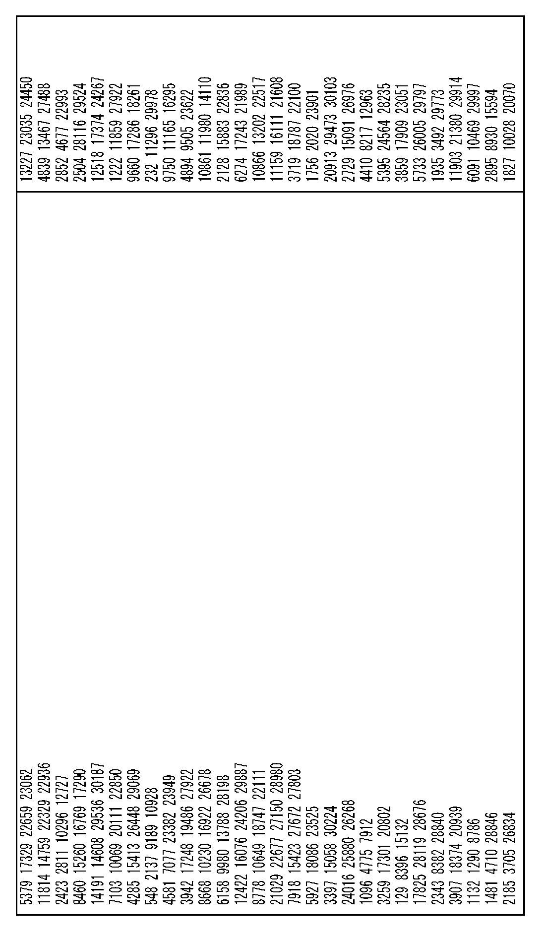
- Each LDPC code is completely defined by a table that contains, for the first bit of each cyclic block in the information part, the index of each check node to which that first bit is connected. Note that the check node index starts from 0. These indexes are called “addressesaddressof the parity bit accumulators” in the DVB-S2 standard.
- FIG. 4 shows a table for an LDPC code, an example of which is shown in FIG.
- FIG. 5 is a diagram showing a PCM information part for the first bit in each cyclic block of the information part for the RA QC LDPC code of FIG.
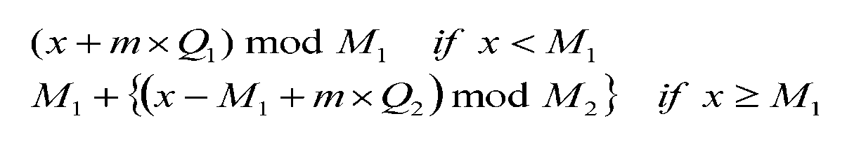
- the index of each check node to which the bit is connected is calculated using the following equation (1).
- q is a bit index (0,..., Q ⁇ 1) within one cyclic block.
- i q is the index of the check node for bit q.
- i 0 is one of the check nodes to which the first bit of the cyclic block in the table of FIG. 4 is connected.
- % Is the modulo operator. For example, for the cyclic block QB of “1”, the calculation using the above equation 1 is performed for each of i 0 13, 24, 27, 31, 47 in the case of FIG. Is called.
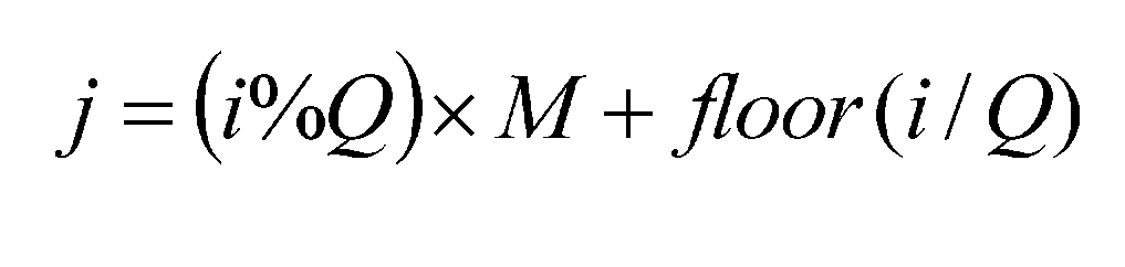
- Equation 2 the permutation represented by the following Equation 2 is applied to the PCM row of FIG. 6, and the matrix is shown in FIG. 7 by the application of this permutation. It will be a thing.
- i and j are indexes starting from zero.
- i is the index of the check node before rearrangement
- j is the index of the check node after rearrangement.
- M is the number of cyclic blocks in the parity part, which is 6 in the example of FIG. 6, and Q is the number of bits of one cyclic block, which is 8 in the example of FIG. % Is a modulo operator
- floor (x) is a function that outputs the largest integer less than or equal to x.
- i and j are indexes starting from zero, i is an index of parity bits before rearrangement, and j is an index of parity bits after rearrangement.
- M is the number of cyclic blocks in the parity part, which is 6 in the example of FIG. 7, and Q is the number of bits of one cyclic block, which is 8 in the example of FIG. % Is a modulo operator, and floor (x) is a function that outputs the largest integer less than or equal to x.
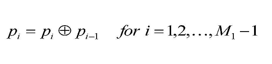
- parity permutation or parity interleaving permutation using the number 3 applied only to the parity bit is referred to as parity permutation or parity interleaving throughout this document.
- parity permutation or parity interleaving is hereinafter regarded as a part of the LDPC encoding process.
- the ATSC 3.0 standard which is the next generation standard for terrestrial reception of digital video services, is currently under development, with coding rates of 1/15, 2/15, ..., 13/15, codeword length 16200 code bits and 64800 code bits will be defined.
- the QAM mapper 124 independently modulates the real component and the imaginary component using pulse-amplitude modulation (PAM), thereby converting the bits of the codeword into one of the QAM constellation points. Map to points. Each point of the QAM constellation corresponds to one combination of bits.
- 8A-8C are diagrams illustrating three types of QAM constellations related to the present disclosure, a 4-QAM constellation, a 16-QAM constellation, and a 64-QAM constellation.
- the same type of PAM is used for the real and imaginary components.
- the same type of PAM is used for the real and imaginary components.
- the 16-QAM constellation, and the 64-QAM constellation, 2-PAM, 4-PAM, and 8-PAM are used for the real component and the imaginary component, respectively.
- This disclosure also assumes that Gray coding is used for PAM mapping, as shown in FIGS. 8A-8C.
- the 9A, 9B, and 9C are blocks showing the configuration of the QAM mapper corresponding to the constellation shown in FIGS. 8A, 8B, and 8C, respectively.
- the 4-QAM mapper 124A of FIG. 9A is composed of two independent 2-PAM mappers 124A-1 and 124A-2, each encoding one bit.
- the 16-QAM mapper 124B of FIG. 9B comprises two independent 4-PAM mappers 124B-1 and 124B-2, each encoding 2 bits.
- the 64-QAM mapper 124C of FIG. 9C consists of two independent 8-PAM mappers 124C-1 and 124C-2, each encoding 3 bits.
- the bits encoded in the PAM symbol have different robust levels, in other words, reliability, when the PAM symbol received at the receiver is demapped. This is a well-known fact, and a schematic diagram for illustrating the different robust levels in 8-PAM symbols using Gray coding is shown in FIG.
- the reason why the robust levels are different is that the distance between the portion where the bit value is 0 and the portion where the bit is 1 is different between the three bits b 1 , b 2 and b 3 .
- the reliability of a bit is proportional to the average distance between the portion where the value of the bit is 0 and the portion where the bit is 1. In the example shown in FIG. 10, the bit b 1 has the lowest reliability, the bit b 2 has the second lowest reliability, and the bit b 3 has the highest reliability.
- non-uniform constellations were first introduced in the DVB-NGH standard. This increase is achieved by changing the spacing between points of the PAM constellation, resulting in so-called 1D-NU-PAMs. Then, a square non-uniform constellation is obtained from 1D-NU-PAMs.
- the number of QAM symbol bits is represented by B. Since the QAM constellation is square, B is an even number. Furthermore, since a square QAM symbol consists of two identical types of PAM symbols, the bits encoded in the QAM symbol can be grouped into pairs with the same robust level. A collection of bits encoded in a QAM symbol is called a constellation word.
- bit interleaver 122 Next, the bit interleaver 122 will be described.
- the bits of the LDPC codeword have different importance and the bits of the constellation have different robust levels. If the bits of the LDPC codeword are mapped directly to the bits of the QAM constellation, that is, without interleaving, optimal performance cannot be obtained. In order to prevent this performance degradation, it is necessary to interleave the bits of the codeword before mapping them to the constellation.
- bit interleaver 122 is provided between the LDPC encoder 121 and the QAM mapper 124 as shown in FIG.
- the performance evaluation criterion is a bit error rate (BER) or a frame error rate (FER) as a function of a signal-to-noise ratio (SNR).
- the reason why the bits of LDPC codewords are different in importance is that the number of parity checks (check nodes) is not the same for all bits. The more parity checks (check nodes) that are connected to a codeword bit (variable node), the more important that bit is in the iterative LDPC decoding process.
- the importance of the bits of the LDPC codeword is different because secondly, the variable node has different connectivity to the cycle in the turner graph representation of the LDPC code. Therefore, even if the number of parity checks (check nodes) connected to the code word bits of the LDPC code is the same, the importance of the bits may be different.
- Patent Document 1 (EP11006087.8), which is fully incorporated herein.
- Patent Document 1 (EP11006087.8) relates to an arbitrary number T of transmission antennas, but in the following, a case related to the present disclosure, that is, a case where the number of transmission antennas T is 1 will be described.
- the bits of the QC LDPC codeword are (I) Each constellation word is made up of B / 2 cyclic block bits of a QC LDPC codeword; (Ii) each pair of bits of the constellation word encoded in the same QAM symbol and having the same robust level is made up of bits of the same cyclic block; Are mapped to constellation words as follows.
- Q ⁇ B / 2 bits of B / 2 cyclic blocks are mapped to Q / 2 spatial multiplexing blocks.
- B / 2 cyclic blocks are called sections.
- 12A to 12C are diagrams for explaining an example of the BICM encoder 120 in FIG.
- FIG. 12A shows an arrangement for 24 cyclic blocks in 4 sections.
- FIG. 12B is a diagram illustrating an example of a path structure from the bit interleaver 122 of the BICM encoder 120 of FIG. 2 to the QAM mapper 124 (including a pair of PAM mappers 124-1 and 124-2) based on DVB-NGH. is there.
- the LDPC codeword generated by the LDPC encoder 121 of FIG. 2 is supplied to the bit interleaver 122 of FIG. 12B.
- the bit interleaver 122 is 6 cyclic blocks per section. 12A is processed by the bit interleaver 122 and the QAM mapper 124 (including a pair of PAM mappers 124-1 and 124-2) in FIG. 12B.
- the bit interleaver 122 changes the order of the supplied bits, and then arranges the rearranged bits in the real part and imaginary part of the corresponding constellation word.
- the pair of PAM mappers 124-1 and 124-2 uses the 64-PAM constellation to convert the bits (b1 , Re , b2 , Re ,..., B6 , Re ) to the real component of the complex symbol s1.
- the (Re), bit (b 1, Im, b 2 , Im, ⁇ , b 6, Im) to be mapped to the imaginary component (Im) of the complex symbols s1.
- FIG. 12C is a diagram for explaining the bit rearrangement executed by the bit interleaver 122 in FIG. 12B.
- the bit interleaver 122 writes all bits of one section of the codeword to the matrix in the row direction (row-by-row), and writes the written bits from the matrix in the column direction (column-by-row).
- Column Perform a process equivalent to reading.
- This matrix is B / 2 rows and Q columns.
- FIGS. 12A to 12C are diagrams for explaining another example of the BICM encoder 120 in FIG. 13A to 13C are similar to FIGS. 12A to 12C, respectively, except that they show an arrangement based on ATSC 3.0.
- FIG. 13A shows the arrangement for 24 cyclic blocks in two sections.
- the number of cyclic blocks per section is the number of bits B of the QAM symbol, and is 12 in the example of FIG. 13A.
- FIG. 13B is a diagram illustrating an example of a path structure from the bit interleaver 122 to the QAM mapper 124 of the BICM encoder 120 of FIG. 2 based on ATSC 3.0.
- the LDPC codeword generated by the LDPC encoder 121 of FIG. 2 is supplied to the bit interleaver 122 of FIG. 13B.
- the bit interleaver 122 is 12 cyclic blocks per section. Note that each section of FIG. 13A is processed by the bit interleaver 122 and the QAM mapper 124 of FIG. 13B.
- the bit interleaver 122 changes the arrangement order of the supplied bits.
- the QAM mapper 124 maps the bits (b 0 , b 1 ,..., B 11 ) to the complex symbol s 1 using a 4096-QAM constellation.
- FIG. 13C is a diagram for explaining the bit rearrangement executed by the bit interleaver 122 of FIG. 13B.
- the bit interleaver 122 writes all bits of one section of the codeword to the matrix in the row direction (row-by-row), and writes the written bits from the matrix in the column direction (column-by-row).
- Column Perform a process equivalent to reading.
- This matrix has B rows and Q columns.
- the cyclic blocks having different predetermined LDPC codes may have different importance levels because the importance levels of the bits depend on the number of check nodes to which the bits are connected. Therefore, the transmission performance may be improved by combining the importance of the cyclic block with the robustness of the bits of the constellation word to which the cyclic block is mapped.
- the bit of the cyclic block having the highest importance is mapped to the bit of the constellation word having the strongest robustness.
- the bit of the least significant cyclic block is mapped to the bit of the constellation word that is the least robust.
- FIG. 14 is a block diagram illustrating a configuration example of the bit interleaver according to the embodiment of the present disclosure.
- the cyclic block permutation is performed on the codeword in order to change the order of the cyclic blocks in the codeword without affecting the order of the bits in the cyclic block. (QB permutation: QB permutation) is executed. This first stage process is performed by the cyclic block permutation unit 210.
- intra-QB permutation Intra-QB permutation
- the processing of the second stage is executed by the intra-cyclic block permutation units 220-1 to 220-12. Note that the second stage may not exist.
- the bits of each cyclic block of the codeword are mapped to the constellation word.
- This third stage can be implemented by dividing the codeword into a plurality of sections and mapping each section to a constellation word (section permutation). For example, it is realized by arranging an interleaver (section interleaver) having a function equivalent to that of the bit interleaver 122 described with reference to FIGS. 13A to 13C at the subsequent stage of the permutation unit in the cyclic block.
- the inventor can determine a given LDPC code by optimizing the cyclic block permutation, i.e., by selecting a cyclic block permutation that combines constellation bits of different reliability with cyclic blocks of different importance. I realized that the communication performance for
- mapping of cyclic blocks to constellation word bits is not easy. Finding an optimized cyclic block permutation is a time consuming task because no analytical solution is currently known.
- the method used to find the optimal cyclic block permutation disclosed in this disclosure consists of the following steps, applied for each of different constellations and different code rates.
- a very large number (1e4... 1e5) of cyclic block permutations are randomly generated without restriction.
- the Monte-Carlo simulation calculates a threshold signal-to-noise ratio (SNR) at a predetermined target value of block error rate (BLER). This is done using blind demapping and iterative demapping. The cyclic block permutation with the lowest threshold SNR, that is, the best performance is retained.
- SNR signal-to-noise ratio
- the inventor realized that the optimization of cyclic block permutation for blind demapping does not achieve optimal performance with iterative demapping, and vice versa. Finding cyclic block permutation that provides good performance for both blind and iterative demapping remains a difficult task.
- the SNR range for various cyclic block permutations is determined. Then, the threshold SNR is set to select only cyclic block permutation that provides good performance for blind demapping. Good performance means low SNR. The threshold SNR should not be set too low. This is because if the threshold SNR is set too low, many cyclic block permutations that can provide very good performance for iterative demapping are excluded. On the other hand, when cyclic block permutation that is strictly optimized for blind demapping is used for iterative demapping, performance is degraded. Proper selection of the initial threshold SNR is a matter of experience.
- a large number of cyclic block permutations are randomly generated without restriction.
- a BLER curve for blind demapping is determined using, for example, Monte-Carlo simulation. Only cyclic block permutations in which the SNR at the BLER target value is lower than a predetermined threshold SNR are retained. A BLER curve regarding iterative demapping is obtained for the retained cyclic block permutation, and the best cyclic block permutation is retained.
- a medium number of cyclic block permutations obtained from the cyclic block permutation selected in the first selection step are randomly generated under restriction.
- the selection criteria of the first selection step are then applied.
- the constrained cyclic block permutation is obtained by applying random permutation to the cyclic block of one randomly selected section. Applying this constraint ensures that the performance change is small and concentrates around the good performance cyclic block permutation already selected in the first selection step. In this way, it is possible to find a more efficient cyclic block permutation than using a search that is not subject to blind constraints.
- a medium number of cyclic block permutations obtained from the cyclic block permutation selected in the second selection step are randomly generated under restriction.
- the selection criteria of the first selection step are then applied.
- the constrained cyclic block permutation is obtained by applying random permutation to bits having the same robust level.
- the inventor has performed optimization of cyclic block permutation for coding rates of 6/15, 7/15, and 8/15, respectively.
- the inventor also determined the optimal non-uniform constellation to be used with the coding rates 6/15, 7/15, and 8/15 simultaneously with the optimization of the cyclic block permutation.
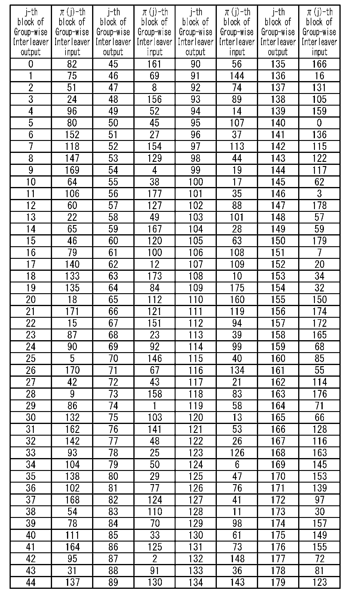
- optimized QB permutation and non-uniform constellation for code rates 6/15, 7/15, and 8/15, respectively, are shown.
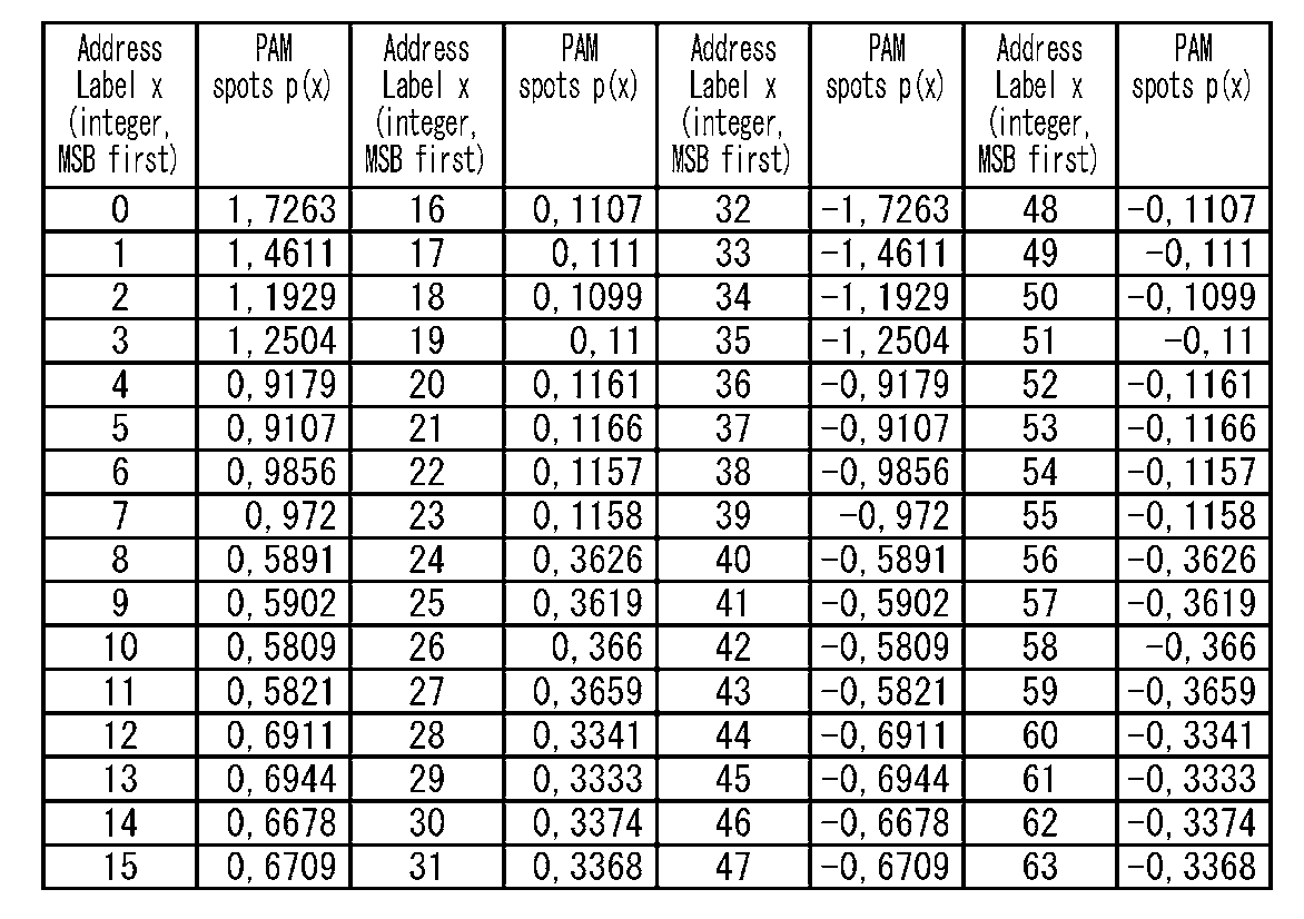
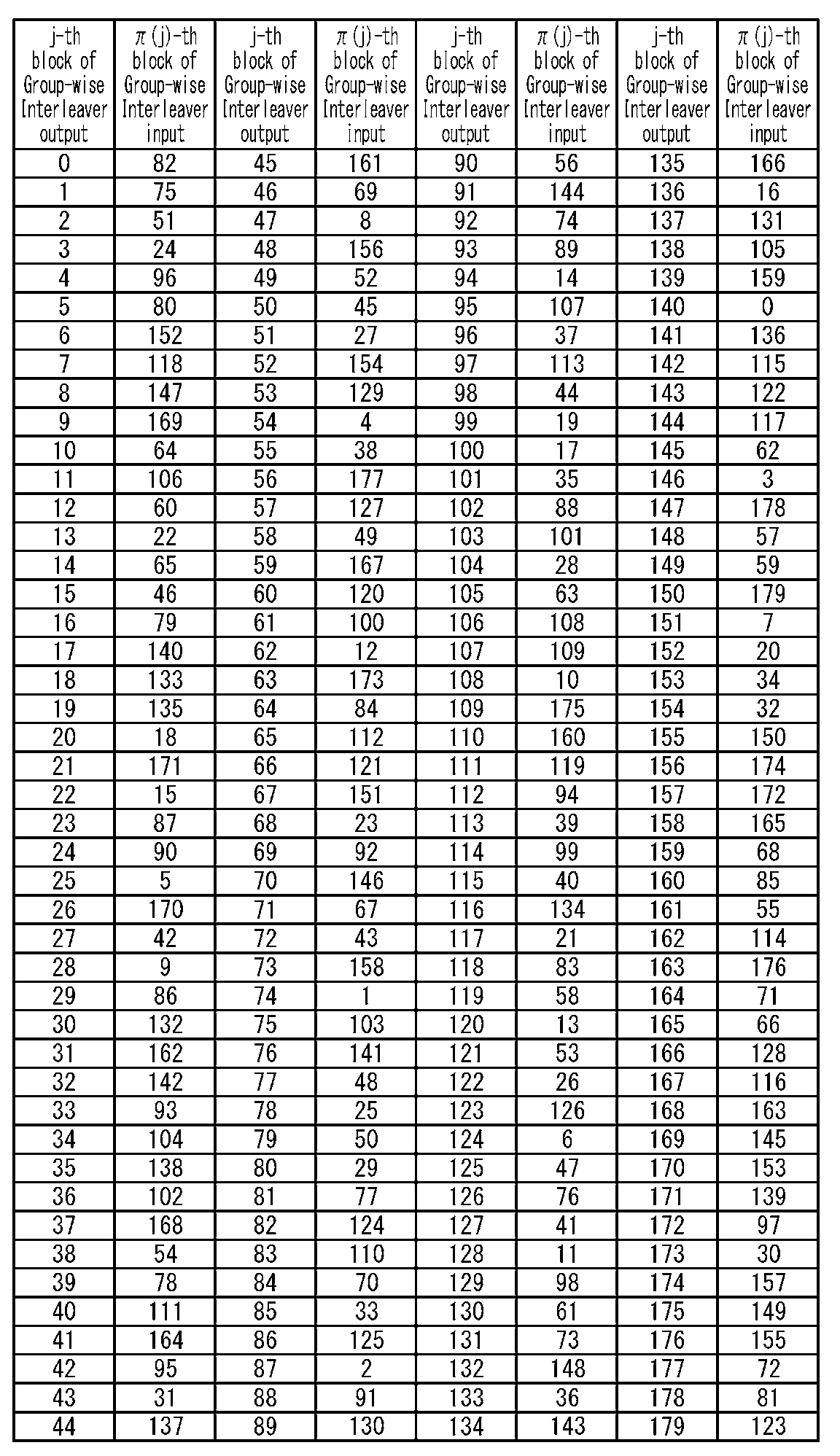
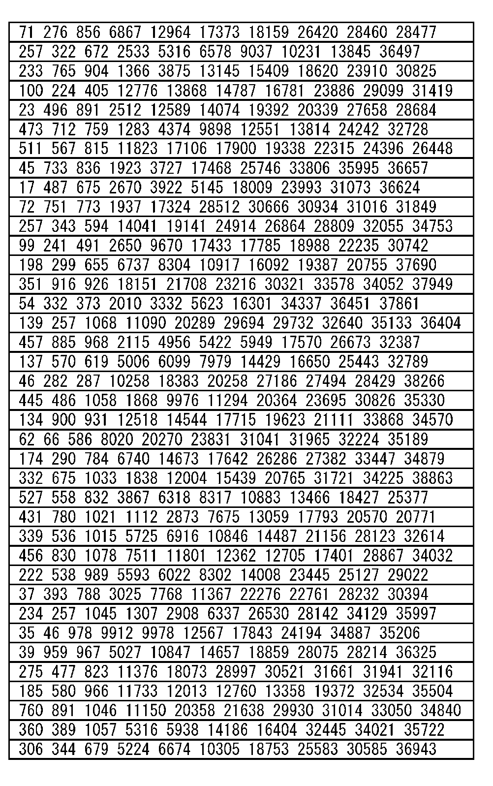
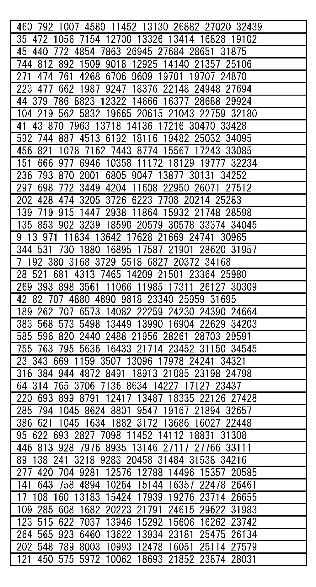
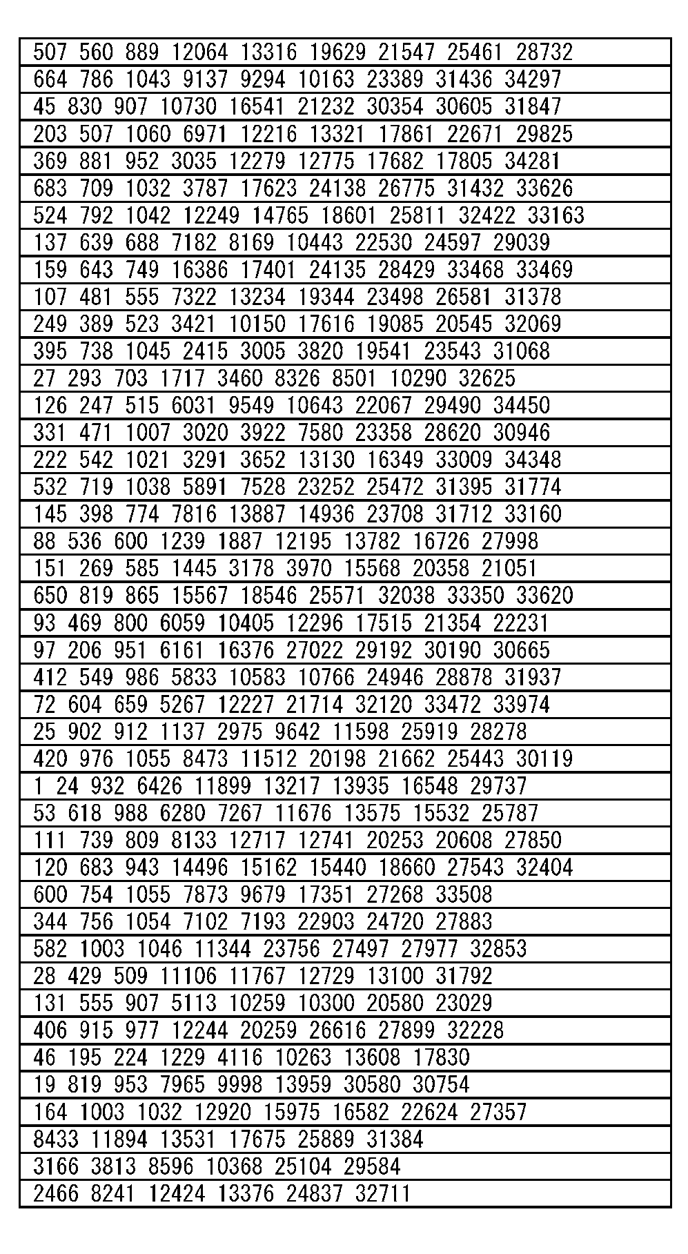
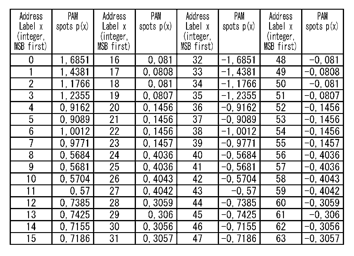
- Tables 1 and 2 are tables showing non-uniform 64-PAM constellations constituting cyclic block permutation and non-uniform 4096-QAM constellations, respectively, when the coding rate according to the present disclosure is 6/15. It is.
- the index of the cyclic block starts from 0 and extends to 179.
- “J-th block of Group-wise Interleaver Output” indicates an index of the cyclic block in the codeword after the cyclic blocks are rearranged.
- “ ⁇ (j) -thblockthof Group-wise Interleaver Input” indicates an index of the cyclic block in the codeword before the cyclic blocks are rearranged.
- the address label x starts from 0 and reaches 63.
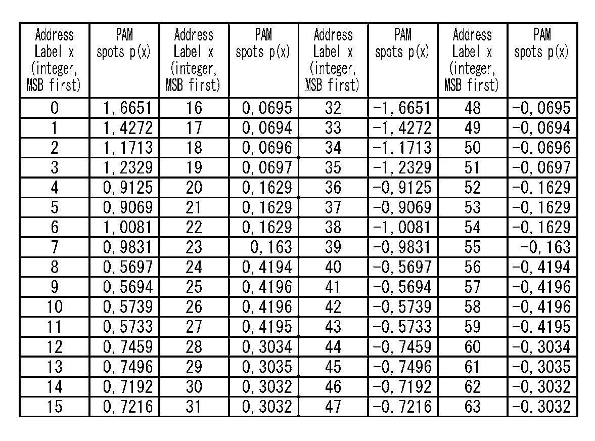
- Tables 3 and 4 are tables showing the non-uniform 64-PAM constellation constituting the cyclic block permutation and the non-uniform 4096-QAM constellation when the coding rate according to the present disclosure is 7/15, respectively. It is.
- Tables 5 and 6 are tables showing non-uniform 64-PAM constellations constituting cyclic block permutation and non-uniform 4096-QAM constellations when the coding rate according to the present disclosure is 8/15, respectively. It is.
- the cyclic block permutation unit 210 in FIG. 14 corresponds to the coding rate of the code used by the LDPC encoder 121 according to the coding rates 6/15, 7/15, and 8/15 according to Table 1, Based on the cyclic block permutation in Table 3 and Table 5, the cyclic blocks in the codeword are rearranged.
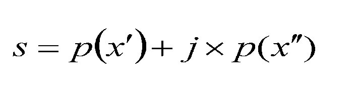
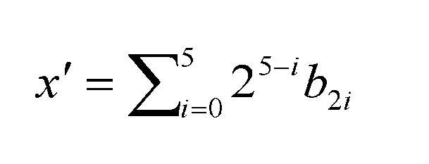
- the mapping to the complex cell s (Re, Im) by the QAM mapper 124 is performed by calculating the following equation (4).
- the non-uniform PAM coordinate p (x) is obtained from Table 2 when the coding rate is 6/15, from Table 4 when the coding rate is 7/15, and from Table 6 when the coding rate is 8/15. can get.
- the address label x ′ of the real part p (x ′) is an interleaver (section interleaver) having a function equivalent to that of the bit interleaver 122 described with reference to FIGS.
- the number of cyclic blocks per section is calculated from Equation 5 using even-numbered bits b 0 , b 2 , b 4 , b 6 , b 8 , b 10 output from B).
- the address label x ′′ of the imaginary part p (x ′′) is expressed by Equation 6 using odd-numbered bits b 1 , b 3 , b 5 , b 7 , b 9 , b 11 output from the section interleaver.
- the cyclic block permutation described above (eg, Table 1, Table 3, Table 5) and non-uniform QAM constellation (eg, Table 2, Table 4, Table 6) can be applied to both the transmitter side and the receiver in a digital communication system.
- Each of the cyclic block permutations described above uniquely defines an inverse cyclic block permutation, and one of the cyclic block permutations described above is used for bit interleaving at the transmitter side, and the reverse cyclic block permutation. Permutation is used for bit deinterleaving at the receiver side.
- mapping the constellation word or codeword bit to the complex cell used for transmission is performed at the transmitter.
- the demapping of the received complex cell is performed at the receiver on the other side of the communication channel.
- the cyclic block permutation described above and the non-uniform 4096-QAM constellation described above are optimized for special LDPC codes with coding rates of 6/15, 7/15, and 8/15, respectively. .
- Tables 7-1 and 7-2 show the definitions of LDPC codes with a code length of 6/15 and a code length of 64,800 code bits. Actually, the definition of the LDPC code is completed when the last row of Table 7-1 is followed by the first row of Table 7-2.
- Table 8-1 and Table 8-2 show the definitions of LDPC codes with a code length of 7/15 and a code length of 64,800 code bits. Actually, the definition of the LDPC code is completed when the last row of Table 8-1 is followed by the first row of Table 8-2.
- Tables 9-1 and 9-2 show the definitions of LDPC codes with a coding length of 8/15 and a code length of 64,800 code bits. Actually, the definition of the LDPC code is completed when the last row of Table 9-1 is followed by the first row of Table 9-2.
- LDPC codes with coding rates of 6/15 and 7/15 are defined based on the following algorithm.
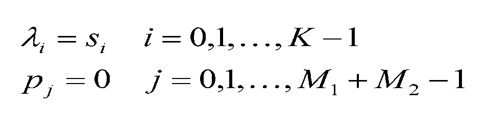
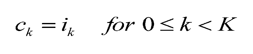
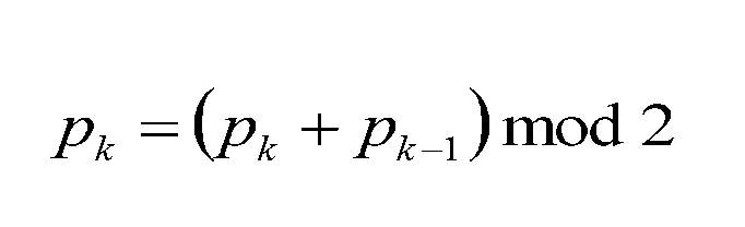
- the LDPC encoder 121 calculates parity bits as follows.
- x represents the address of the parity bit accumulator corresponding to the first bit ⁇ 0 .
- mod represents a modulo operator (the same applies hereinafter).
- x is the address of the lambda L, a second row of values of definition if based on Table 7-1 and Table 7-2 coding rate 6/15, if table of the encoding rate 7/15 8 -1 and the value in the second row of the definition based on Table 8-2.
- x indicates an address corresponding to the first code bit of each group of codeword bits, and in the case of a coding rate of 6/15, the row corresponding to each group defined in Table 7-1 and Table 7-2. This is a value of a row corresponding to each group of definitions based on Table 8-1 and Table 8-2 when the coding rate is 7/15.
- LDPC code with a coding rate of 8/15 is defined by the following algorithm.
- N 64800
- K N ⁇ coding rate
- w (i) is the number of elements in the i-th row in the index list based on the definitions based on Tables 9-1 and 9-2.
- parity interleaver The role of the parity interleaver is to convert the stepped structure of the parity part of the LDPC parity check matrix into a pseudo cyclic structure similar to the information part of the matrix. Parity-interleaved codeword bits c 0 , c 1 ,..., C N ⁇ 1 are sent to cyclic block permutation unit 210 of the bit interleaver.
- Parameter q (i, j, 0) indicates the j-th entry in the i-th row in the index list based on the definitions based on Table 9-1 and Table 9-2, and satisfies the relationship of Equation 19.
- the present disclosure is in the form of a computer-readable medium embodying computer-executable instructions adapted to allow a computer, microprocessor, microcontroller, etc. to perform all the steps of the methods according to the embodiments of the present disclosure. May be implemented.
- ASIC Application-Specific Integrated Circuit
- FPGA Field Programmable Gate Array
- the present disclosure relates to a digital communication system based on a QC LDPC code and a higher-order constellation.
- the present disclosure provides special permutation for reordering bits of an LDPC code and special non-uniform constellation for transmitting interleaved codewords. Permutation and non-uniform constellation are optimized in concert at a coding rate of 6/15, 7/15, or 8/15.
- a first communication method is a data communication method for performing data communication in a digital communication system using a pseudo cyclic low density parity check code including a repeat accumulating pseudo cyclic low density parity check code, the pseudo cyclic parity Cyclic block permutation is performed on a codeword generated based on a check code, and the codeword is composed of a sequence of N cyclic blocks, and each of the N cyclic blocks is composed of Q bits.
- N and Q are each a positive integer
- the cyclic block permutation is a reordering of cyclic blocks within the codeword, an interleaving step, and a code on which the cyclic block permutation has been executed.
- the second communication method is the first communication method
- the coding rate of the pseudo cyclic low density parity check code is 6/15
- the non-uniform constellation is a non-uniform 64-PAM constellation in which real coordinates and imaginary coordinates are respectively given according to Table 2 above.
- Uniform 4096-QAM constellation is a non-uniform 64-PAM constellation in which real coordinates and imaginary coordinates are respectively given according to Table 2 above.
- the coding rate of the pseudo cyclic low density parity check code is 6/15, and the cyclic block permutation is as shown in Table 1 above. Defined according to
- the fourth communication method is the first communication method, wherein the pseudo cyclic low density parity check code has a coding rate of 7/15, and the non-uniform constellation has real and imaginary coordinates, respectively.
- a non-uniform 4096-QAM constellation which is a non-uniform 64-PAM constellation given according to Table 4 above.
- the fifth communication method is the first or fourth communication method, wherein the coding rate of the pseudo cyclic low density parity check code is 7/15, and the cyclic block permutation is as shown in Table 3 above. Defined according to
- the sixth communication method is the first communication method, wherein the coding rate of the pseudo cyclic low density parity check code is 8/15, and the non-uniform constellation has real and imaginary coordinates, respectively.
- a non-uniform 4096-QAM constellation which is a non-uniform 64-PAM constellation given according to Table 6 above.
- the coding rate of the pseudo cyclic low density parity check code is 8/15, and the cyclic block permutation is as shown in Table 5 above. Defined according to
- the eighth communication method is any one of the first to seventh communication methods, wherein N is 180 and Q is 360.
- the ninth communication method is any one of the first to eighth communication methods, wherein the pseudo cyclic parity check code used for generating the codeword is a plurality of predetermined pseudo cyclics having different coding rates. A parity check code is selected.
- the first communication device is a communication device in a digital communication system that performs any one of the first to ninth communication methods.
- a tenth communication method is a data communication method for performing data communication in a digital communication system using a pseudo cyclic low density parity check including a repeat accumulated pseudo cyclic low density parity check code, the pseudo cyclic low density parity Cyclic block permutation is performed on the codeword generated based on the check code, and the bits of the codeword subjected to cyclic block permutation are obtained by constellation mapping of non-uniform constellation. For each of the complex cells, demapping based on the non-uniform constellation is performed, and a process reverse to the cyclic block permutation is performed on the demapping result.
- the second communication device is a communication device in a digital communication system that performs the tenth communication method.
- the present disclosure can be used for a BICM system using a QC LDPC code and QAM.
Landscapes
- Engineering & Computer Science (AREA)
- Physics & Mathematics (AREA)
- Probability & Statistics with Applications (AREA)
- Theoretical Computer Science (AREA)
- Computer Networks & Wireless Communication (AREA)
- Signal Processing (AREA)
- Mathematical Physics (AREA)
- Multimedia (AREA)
- Error Detection And Correction (AREA)
- Detection And Prevention Of Errors In Transmission (AREA)
Abstract
Description
図1は、一般的なビットインタリーブ符号化変調(bit-interleaved coding and modulation:BICM)を含む送信機の一構成例を示すブロック図である。


(i)各コンステレーションワードはQC LDPC符号語のB/2個の巡回ブロックのビットから作られ、
(ii)同じQAMシンボルに符号化され、ロバストレベルが同じである、コンステレーションワードのビットの各ペアは、同じ巡回ブロックのビットから作られる、
ようにコンステレーションワードにマッピングされる。
上述したように、所定のLDPC符号の異なる巡回ブロックは、ビットの重要度が当該ビットが接続される検査ノードの数に依存するため、重要度が異なっている可能性がある。従って、巡回ブロックの重要度と、この巡回ブロックがマップされるコンステレーションワードのビットのロバストとを合わすことによって、送信性能の向上が図られる可能性がある。特に、重要度が最も高い巡回ブロックのビットを、ロバストが最も強いコンステレーションワードのビットにマッピングする。逆に、重要度が最も低い巡回ブロックのビットを、ロバストが最も弱いコンステレーションワードのビットにマッピングする。


本開示は上記の実施の形態で説明した内容に限定されず、本開示の目的とそれに関連又は付随する目的を達成するためのいかなる形態においても実施可能であり、例えば、以下であってもよい。
本開示に係る通信方法等についてまとめる。
前記疑似巡回低密度パリティ検査符号の符号化率が6/15であり、前記非均一コンステレーションが、実数座標及び虚数座標が夫々上記の表2に従って与えられる非均一64-PAMコンステレーションである非均一4096-QAMコンステレーションである。
110 入力プロセシングユニット
120 BICMエンコーダ
130 OFDMモジュレータ
140 アップコンバータ
150 RF増幅器
121 LDPCエンコーダ
122 ビットインタリーバ
124 QAMマッパ
210 巡回ブロックパーミュテーションユニット
220-1~220-12 巡回ブロック内パーミュテーションユニット
Claims (12)
- リピートアキュミュレート疑似巡回低密度パリティ検査符号を含む疑似巡回低密度パリティ検査符号を用いるデジタル通信システムにおけるデータ通信を行うデータ通信方法であって、
前記疑似巡回パリティ検査符号に基づいて生成された符号語に対して巡回ブロックパーミュテーションを実行し、前記符号語はN個の巡回ブロックの列からなり、前記N個の巡回ブロックの夫々はQ個のビットからなり、NとQは夫々正の整数であり、前記巡回ブロックパーミュテーションは前記符号語内での巡回ブロックの並び替えである、インタリービングステップと、
前記巡回ブロックパーミュテーションが実行された符号語の各ビットを非均一コンステレーションのコンステレーションポイントにマッピングするコンステレーションマッピングステップと、
を有し、
前記巡回ブロックパーミュテーション及び前記非均一コンステレーションは符号語の生成に用いる前記疑似巡回低密度パリティ検査符号の符号化率に基づいて選択される、
通信方法。 - 前記疑似巡回低密度パリティ検査符号の符号化率が6/15であり、前記非均一コンステレーションが、実数座標及び虚数座標が夫々表1に従って与えられる非均一64-PAMコンステレーションである非均一4096-QAMコンステレーションである、

- 前記疑似巡回低密度パリティ検査符号の符号化率が6/15であり、前記巡回ブロックパーミュテーションが表2に従って定義される、

- 前記疑似巡回低密度パリティ検査符号の符号化率が7/15であり、前記非均一コンステレーションが、実数座標及び虚数座標が夫々表3に従って与えられる非均一64-PAMコンステレーションである非均一4096-QAMコンステレーションである、
- 前記疑似巡回低密度パリティ検査符号の符号化率が7/15であり、前記巡回ブロックパーミュテーションが表4に従って定義される、

- 前記疑似巡回低密度パリティ検査符号の符号化率が8/15であり、前記非均一コンステレーションが、実数座標及び虚数座標が夫々表5に従って与えられる非均一64-PAMコンステレーションである非均一4096-QAMコンステレーションである、
- 前記疑似巡回低密度パリティ検査符号の符号化率が8/15であり、前記巡回ブロックパーミュテーションが表6に従って定義される、
- 前記Nは180、前記Qは360である、
請求項1から請求項7の何れか一項に記載の通信方法。 - 前記符号語の生成に用いる前記疑似巡回パリティ検査符号は、互いに符号化率が異なる複数の所定の疑似巡回パリティ検査符号の中から選択される、
請求項1から請求項8の何れか一項に記載の通信方法。 - 請求項1から請求項9の何れか一項に記載の通信方法を行うデジタル通信システムにおける通信装置。
- リピートアキュミュレート疑似巡回低密度パリティ検査符号を含む疑似巡回低密度パリティ検査を用いるデジタル通信システムにおけるデータ通信を行うデータ通信方法であって、
前記疑似巡回低密度パリティ検査符号に基づいて生成された符号語に対して巡回ブロックパーミュテーションが実行され、巡回ブロックパーミュテーションが実行された符号語のビットが非均一コンステレーションのコンステレーションマッピングされることにより得られた複素セルの夫々に対して、当該非均一コンステレーションに基づくデマッピングを行い、
デマッピングの結果に対して前記巡回ブロックパーミュテーションと逆の処理を行う、
通信方法。 - 請求項11記載の通信方法を行うデジタル通信システムにおける通信装置。
Priority Applications (22)
| Application Number | Priority Date | Filing Date | Title |
|---|---|---|---|
| EP22187290.6A EP4113925B1 (en) | 2014-05-22 | 2015-05-19 | Communication method and communication device |
| KR1020217015429A KR102336457B1 (ko) | 2014-05-22 | 2015-05-19 | 통신 방법 및 통신 장치 |
| CN201911298655.0A CN111049532B (zh) | 2014-05-22 | 2015-05-19 | 通信方法及通信装置 |
| KR1020217039457A KR102400538B1 (ko) | 2014-05-22 | 2015-05-19 | 통신 방법 및 통신 장치 |
| CN201580015534.4A CN106165301B (zh) | 2014-05-22 | 2015-05-19 | 通信方法及通信装置 |
| KR1020237022424A KR102652135B1 (ko) | 2014-05-22 | 2015-05-19 | 통신 방법 및 통신 장치 |
| CA2943174A CA2943174C (en) | 2014-05-22 | 2015-05-19 | Communication method and communication device |
| KR1020227016025A KR102552235B1 (ko) | 2014-05-22 | 2015-05-19 | 통신 방법 및 통신 장치 |
| KR1020167019915A KR101751662B1 (ko) | 2014-05-22 | 2015-05-19 | 통신 방법 및 통신 장치 |
| KR1020207037186A KR102257962B1 (ko) | 2014-05-22 | 2015-05-19 | 통신 방법 및 통신 장치 |
| EP15796489.1A EP3148089B1 (en) | 2014-05-22 | 2015-05-19 | Communication method and communication device |
| MX2018009641A MX387373B (es) | 2014-05-22 | 2015-05-19 | Método de comunicación y dispositivo de comunicación. |
| EP20188709.8A EP3751810B1 (en) | 2014-05-22 | 2015-05-19 | Communication method and communication device |
| KR1020257009622A KR102908924B1 (ko) | 2014-05-22 | 2015-05-19 | 통신 방법 및 통신 장치 |
| MX2016012888A MX358339B (es) | 2014-05-22 | 2015-05-19 | Metodo de comunicacion y dispositivo de comunicacion. |
| KR1020177016822A KR102197545B1 (ko) | 2014-05-22 | 2015-05-19 | 통신 방법 및 통신 장치 |
| KR1020247009709A KR102788718B1 (ko) | 2014-05-22 | 2015-05-19 | 통신 방법 및 통신 장치 |
| US15/271,203 US10355816B2 (en) | 2014-05-22 | 2016-09-20 | Communication method and communication device |
| US16/427,762 US10979173B2 (en) | 2014-05-22 | 2019-05-31 | Communication method and communication device |
| US17/194,661 US11362761B2 (en) | 2014-05-22 | 2021-03-08 | Communication method and communication device |
| US17/743,783 US11916665B2 (en) | 2014-05-22 | 2022-05-13 | Communication method and communication device |
| US18/413,573 US12526071B2 (en) | 2014-05-22 | 2024-01-16 | Communication method and communication device |
Applications Claiming Priority (4)
| Application Number | Priority Date | Filing Date | Title |
|---|---|---|---|
| EP14169535.3 | 2014-05-22 | ||
| EP14169535.3A EP2947836A1 (en) | 2014-05-22 | 2014-05-22 | Cyclic-block permutations for 1D-4096-QAM with quasi-cyclic LDPC codes and code rates 6/15, 7/15, and 8/15 |
| JP2015090218A JP6423309B2 (ja) | 2014-05-22 | 2015-04-27 | 通信方法 |
| JP2015-090218 | 2015-04-27 |
Related Child Applications (1)
| Application Number | Title | Priority Date | Filing Date |
|---|---|---|---|
| US15/271,203 Continuation US10355816B2 (en) | 2014-05-22 | 2016-09-20 | Communication method and communication device |
Publications (1)
| Publication Number | Publication Date |
|---|---|
| WO2015178011A1 true WO2015178011A1 (ja) | 2015-11-26 |
Family
ID=54553692
Family Applications (1)
| Application Number | Title | Priority Date | Filing Date |
|---|---|---|---|
| PCT/JP2015/002504 Ceased WO2015178011A1 (ja) | 2014-05-22 | 2015-05-19 | 通信方法および通信装置 |
Country Status (6)
| Country | Link |
|---|---|
| US (2) | US11916665B2 (ja) |
| EP (1) | EP4113925B1 (ja) |
| KR (6) | KR102788718B1 (ja) |
| CN (1) | CN111049532B (ja) |
| MX (1) | MX387373B (ja) |
| WO (1) | WO2015178011A1 (ja) |
Families Citing this family (1)
| Publication number | Priority date | Publication date | Assignee | Title |
|---|---|---|---|---|
| WO2015178011A1 (ja) * | 2014-05-22 | 2015-11-26 | パナソニック株式会社 | 通信方法および通信装置 |
Citations (3)
| Publication number | Priority date | Publication date | Assignee | Title |
|---|---|---|---|---|
| JP2011523318A (ja) * | 2008-06-13 | 2011-08-04 | トムソン ライセンシング | Awgnチャネル上の性能を向上させるための適応型qam伝送方式 |
| WO2013014906A1 (en) * | 2011-07-25 | 2013-01-31 | Panasonic Corporation | Interleaving method and deinterleaving method |
| WO2013024584A1 (ja) * | 2011-08-17 | 2013-02-21 | パナソニック株式会社 | インターリービング方法、及びデインターリービング方法 |
Family Cites Families (9)
| Publication number | Priority date | Publication date | Assignee | Title |
|---|---|---|---|---|
| JP2552043Y2 (ja) | 1991-01-17 | 1997-10-27 | 日信工業 株式会社 | 負圧ブースタ |
| JP3139909B2 (ja) * | 1994-03-15 | 2001-03-05 | 株式会社東芝 | 階層的直交周波数多重伝送方式および送受信装置 |
| EP2525495A1 (en) * | 2011-05-18 | 2012-11-21 | Panasonic Corporation | Bit-interleaved coding and modulation (BICM) with quasi-cyclic LDPC codes |
| KR101246460B1 (ko) * | 2011-07-28 | 2013-03-21 | 현대제철 주식회사 | 턴디쉬의 침지 노즐용 예열 장치 |
| EP2690790A1 (en) * | 2012-07-27 | 2014-01-29 | Panasonic Corporation | Bit interleaving for rotated constellations with quasi-cyclic LDPC codes |
| US20160261288A1 (en) | 2013-09-26 | 2016-09-08 | Sony Corporation | Data processing device and data processing method |
| WO2015178011A1 (ja) * | 2014-05-22 | 2015-11-26 | パナソニック株式会社 | 通信方法および通信装置 |
| EP2947836A1 (en) * | 2014-05-22 | 2015-11-25 | Panasonic Corporation | Cyclic-block permutations for 1D-4096-QAM with quasi-cyclic LDPC codes and code rates 6/15, 7/15, and 8/15 |
| KR102552043B1 (ko) | 2021-10-28 | 2023-07-06 | 강길영 | 전방향성 rf 방향탐지 및 지향성 레이더 탐지를 조합 사용하여 침입 드론의 위치를 측정 및 교란하기 위한 시스템 및 방법 |
-
2015
- 2015-05-19 WO PCT/JP2015/002504 patent/WO2015178011A1/ja not_active Ceased
- 2015-05-19 KR KR1020247009709A patent/KR102788718B1/ko active Active
- 2015-05-19 EP EP22187290.6A patent/EP4113925B1/en active Active
- 2015-05-19 CN CN201911298655.0A patent/CN111049532B/zh active Active
- 2015-05-19 KR KR1020217015429A patent/KR102336457B1/ko active Active
- 2015-05-19 KR KR1020227016025A patent/KR102552235B1/ko active Active
- 2015-05-19 MX MX2018009641A patent/MX387373B/es unknown
- 2015-05-19 KR KR1020237022424A patent/KR102652135B1/ko active Active
- 2015-05-19 KR KR1020217039457A patent/KR102400538B1/ko active Active
- 2015-05-19 KR KR1020257009622A patent/KR102908924B1/ko active Active
-
2022
- 2022-05-13 US US17/743,783 patent/US11916665B2/en active Active
-
2024
- 2024-01-16 US US18/413,573 patent/US12526071B2/en active Active
Patent Citations (3)
| Publication number | Priority date | Publication date | Assignee | Title |
|---|---|---|---|---|
| JP2011523318A (ja) * | 2008-06-13 | 2011-08-04 | トムソン ライセンシング | Awgnチャネル上の性能を向上させるための適応型qam伝送方式 |
| WO2013014906A1 (en) * | 2011-07-25 | 2013-01-31 | Panasonic Corporation | Interleaving method and deinterleaving method |
| WO2013024584A1 (ja) * | 2011-08-17 | 2013-02-21 | パナソニック株式会社 | インターリービング方法、及びデインターリービング方法 |
Non-Patent Citations (1)
| Title |
|---|
| BELKACEM MOUHOUCHE ET AL.: "High order non- uniform constellations for broadcasting UHDTV", WIRELESS COMMUNICATIONS AND NETWORKING CONFERENCE (WCNC, pages 600 - 605, XP032682611 * |
Also Published As
| Publication number | Publication date |
|---|---|
| KR20230105004A (ko) | 2023-07-11 |
| KR102652135B1 (ko) | 2024-03-28 |
| US20240163009A1 (en) | 2024-05-16 |
| MX387373B (es) | 2025-03-18 |
| CN111049532A (zh) | 2020-04-21 |
| KR20220070043A (ko) | 2022-05-27 |
| KR20210062103A (ko) | 2021-05-28 |
| KR102400538B1 (ko) | 2022-05-23 |
| US12526071B2 (en) | 2026-01-13 |
| KR102908924B1 (ko) | 2026-01-08 |
| KR20250048133A (ko) | 2025-04-07 |
| CN111049532B (zh) | 2024-09-24 |
| US11916665B2 (en) | 2024-02-27 |
| EP4113925B1 (en) | 2023-11-15 |
| KR102788718B1 (ko) | 2025-03-31 |
| EP4113925A1 (en) | 2023-01-04 |
| MX2018009641A (es) | 2021-10-26 |
| KR20210149247A (ko) | 2021-12-08 |
| US20220278770A1 (en) | 2022-09-01 |
| KR102552235B1 (ko) | 2023-07-06 |
| KR102336457B1 (ko) | 2021-12-07 |
| KR20240046271A (ko) | 2024-04-08 |
Similar Documents
| Publication | Publication Date | Title |
|---|---|---|
| JP6609684B2 (ja) | 通信方法 | |
| US12526071B2 (en) | Communication method and communication device | |
| EP2947837A1 (en) | Cyclic-block permutations for 1D-4096-QAM with quasi-cyclic LDPC codes and code rates 9/15 and 13/15 |
Legal Events
| Date | Code | Title | Description |
|---|---|---|---|
| 121 | Ep: the epo has been informed by wipo that ep was designated in this application |
Ref document number: 15796489 Country of ref document: EP Kind code of ref document: A1 |
|
| ENP | Entry into the national phase |
Ref document number: 20167019915 Country of ref document: KR Kind code of ref document: A |
|
| ENP | Entry into the national phase |
Ref document number: 2943174 Country of ref document: CA |
|
| REEP | Request for entry into the european phase |
Ref document number: 2015796489 Country of ref document: EP |
|
| WWE | Wipo information: entry into national phase |
Ref document number: MX/A/2016/012888 Country of ref document: MX Ref document number: 2015796489 Country of ref document: EP |
|
| NENP | Non-entry into the national phase |
Ref country code: DE |
|
| WWP | Wipo information: published in national office |
Ref document number: 1020257009622 Country of ref document: KR |