WO2015178479A1 - 正極材料、二次電池、正極材料の製造方法および二次電池の製造方法 - Google Patents
正極材料、二次電池、正極材料の製造方法および二次電池の製造方法 Download PDFInfo
- Publication number
- WO2015178479A1 WO2015178479A1 PCT/JP2015/064730 JP2015064730W WO2015178479A1 WO 2015178479 A1 WO2015178479 A1 WO 2015178479A1 JP 2015064730 W JP2015064730 W JP 2015064730W WO 2015178479 A1 WO2015178479 A1 WO 2015178479A1
- Authority
- WO
- WIPO (PCT)
- Prior art keywords
- positive electrode
- electrode material
- vanadium phosphate
- aluminum
- lithium vanadium
- Prior art date
- Legal status (The legal status is an assumption and is not a legal conclusion. Google has not performed a legal analysis and makes no representation as to the accuracy of the status listed.)
- Ceased
Links
Images













Classifications
-
- H—ELECTRICITY
- H01—ELECTRIC ELEMENTS
- H01M—PROCESSES OR MEANS, e.g. BATTERIES, FOR THE DIRECT CONVERSION OF CHEMICAL ENERGY INTO ELECTRICAL ENERGY
- H01M4/00—Electrodes
- H01M4/02—Electrodes composed of, or comprising, active material
- H01M4/36—Selection of substances as active materials, active masses, active liquids
- H01M4/362—Composites
- H01M4/366—Composites as layered products
-
- H—ELECTRICITY
- H01—ELECTRIC ELEMENTS
- H01M—PROCESSES OR MEANS, e.g. BATTERIES, FOR THE DIRECT CONVERSION OF CHEMICAL ENERGY INTO ELECTRICAL ENERGY
- H01M4/00—Electrodes
- H01M4/02—Electrodes composed of, or comprising, active material
- H01M4/36—Selection of substances as active materials, active masses, active liquids
-
- H—ELECTRICITY
- H01—ELECTRIC ELEMENTS
- H01M—PROCESSES OR MEANS, e.g. BATTERIES, FOR THE DIRECT CONVERSION OF CHEMICAL ENERGY INTO ELECTRICAL ENERGY
- H01M4/00—Electrodes
- H01M4/02—Electrodes composed of, or comprising, active material
- H01M4/36—Selection of substances as active materials, active masses, active liquids
- H01M4/58—Selection of substances as active materials, active masses, active liquids of inorganic compounds other than oxides or hydroxides, e.g. sulfides, selenides, tellurides, halogenides or LiCoFy; of polyanionic structures, e.g. phosphates, silicates or borates
-
- H—ELECTRICITY
- H01—ELECTRIC ELEMENTS
- H01M—PROCESSES OR MEANS, e.g. BATTERIES, FOR THE DIRECT CONVERSION OF CHEMICAL ENERGY INTO ELECTRICAL ENERGY
- H01M4/00—Electrodes
- H01M4/02—Electrodes composed of, or comprising, active material
- H01M4/36—Selection of substances as active materials, active masses, active liquids
- H01M4/58—Selection of substances as active materials, active masses, active liquids of inorganic compounds other than oxides or hydroxides, e.g. sulfides, selenides, tellurides, halogenides or LiCoFy; of polyanionic structures, e.g. phosphates, silicates or borates
- H01M4/5825—Oxygenated metallic salts or polyanionic structures, e.g. borates, phosphates, silicates, olivines
-
- H—ELECTRICITY
- H01—ELECTRIC ELEMENTS
- H01M—PROCESSES OR MEANS, e.g. BATTERIES, FOR THE DIRECT CONVERSION OF CHEMICAL ENERGY INTO ELECTRICAL ENERGY
- H01M4/00—Electrodes
- H01M4/02—Electrodes composed of, or comprising, active material
- H01M4/62—Selection of inactive substances as ingredients for active masses, e.g. binders, fillers
-
- H—ELECTRICITY
- H01—ELECTRIC ELEMENTS
- H01M—PROCESSES OR MEANS, e.g. BATTERIES, FOR THE DIRECT CONVERSION OF CHEMICAL ENERGY INTO ELECTRICAL ENERGY
- H01M4/00—Electrodes
- H01M4/02—Electrodes composed of, or comprising, active material
- H01M4/64—Carriers or collectors
- H01M4/66—Selection of materials
- H01M4/663—Selection of materials containing carbon or carbonaceous materials as conductive part, e.g. graphite, carbon fibres
-
- Y—GENERAL TAGGING OF NEW TECHNOLOGICAL DEVELOPMENTS; GENERAL TAGGING OF CROSS-SECTIONAL TECHNOLOGIES SPANNING OVER SEVERAL SECTIONS OF THE IPC; TECHNICAL SUBJECTS COVERED BY FORMER USPC CROSS-REFERENCE ART COLLECTIONS [XRACs] AND DIGESTS
- Y02—TECHNOLOGIES OR APPLICATIONS FOR MITIGATION OR ADAPTATION AGAINST CLIMATE CHANGE
- Y02E—REDUCTION OF GREENHOUSE GAS [GHG] EMISSIONS, RELATED TO ENERGY GENERATION, TRANSMISSION OR DISTRIBUTION
- Y02E60/00—Enabling technologies; Technologies with a potential or indirect contribution to GHG emissions mitigation
- Y02E60/10—Energy storage using batteries
Definitions
- the present invention relates to a positive electrode material, a secondary battery, a method for manufacturing a positive electrode material, and a method for manufacturing a secondary battery.
- Non-Patent Document 1 A composite of lithium vanadium phosphate (Li 3 V 2 (PO 4 ) 3 ) having a NAS super structure and a conductive carbon material is used as an electrode material of a power storage device such as a secondary battery or an electrochemical capacitor. It is known (for example, see Non-Patent Document 1, Non-Patent Document 2, and Non-Patent Document 3).
- Non-Patent Document 1 X. Rui, et al. , J. et al. PowerSources, 214, 171 (2012) Non-Patent Document 2 Zhang, et al. , J. et al. Power Sources, 203, 121 (2012) Non-Patent Document 3 Pan et al. , “Nano-structured Li 3 V 2 (PO 4 ) 3 / carbon composite for-late lithium-ion batteries”, Electrochemistry Communications, 12, 1647-1677 (10)
- a conventional composite of lithium vanadium phosphate and a conductive carbon material has a good discharge capacity at a discharge rate of less than 80C, but has a problem of a low discharge capacity at a discharge rate of 80C or more.
- the positive electrode material in the first aspect of the present invention includes lithium vanadium phosphate containing vanadium whose valence changes between trivalent and pentavalent by desorption of lithium ions, and a conductive carbon material.
- Lithium vanadium acid is bonded to the surface of the conductive carbon material, and 90% or more of the total weight of the lithium vanadium phosphate is a positive electrode material that is a particle-shaped crystal having a diameter of 10 to 200 nm.
- an aqueous solution of a mixture containing a vanadium source, a conductive carbon material, an organic compound having a plurality of carboxyl groups, and an alcohol having a plurality of hydroxyl groups Applying a shear stress and a centrifugal force in a rotating reaction vessel to bond vanadium oxide to the surface of the conductive carbon material; adding a phosphate source and a lithium source to the mixture; Applying a shear stress and a centrifugal force in a rotating reaction vessel to produce lithium vanadium phosphate bonded in a particle shape to the surface of the conductive carbon material, and producing a positive electrode material comprising Method.
- the cycle characteristics of discharge are shown. It is a flowchart which shows the manufacture procedure of the 1st process of the lithium vanadium phosphate composite body in which gallium or indium was dissolved.
- the charge / discharge characteristics are shown.
- the discharge rate characteristic is shown.
- the charge rate characteristic is shown. It is a figure explaining the ion radius of a metal ion. It is a graph which shows the theoretical capacity
- the cycle characteristics of discharge are shown.
- FIG. 1 is a cross-sectional view schematically showing a lithium secondary battery 10 including the positive electrode material of the present embodiment as a positive electrode.
- the lithium secondary battery 10 includes a battery case 12, an ion conductor 14, a separator 16, a positive electrode 18, and a negative electrode 20.
- the positive electrode 18 and the negative electrode 20 are stacked with the ion conductor 14 interposed therebetween.
- the positive electrode 18 and the negative electrode 20 are inserted into the battery case 12 in a dry air or dry inert gas atmosphere in which the dew point temperature is controlled. Then, the positive electrode terminal 22 connected to the positive electrode 18 and the negative electrode terminal 24 connected to the negative electrode are connected to the load 26, and the battery case 12 is sealed, whereby the lithium secondary battery 10 is assembled.
- the positive electrode material according to the present embodiment includes aluminum, lithium vanadium phosphate including vanadium whose valence changes between trivalent and pentavalent by desorption of lithium ions, and a conductive carbon material. Is dissolved in vanadium phosphate.
- the lithium vanadium phosphate containing aluminum is bonded to the surface of the conductive carbon material, and 90% or more of the total weight of the lithium vanadium phosphate containing aluminum is a crystalline particle having a diameter of 10 to 200 nm. It is.
- bonding means that lithium vanadium phosphate containing aluminum is not physically attached to the surface of the conductive carbon material, but the lithium vanadium phosphate and the conductive carbon material are also electrically connected. In other words, the conductivity is high. For example, lithium vanadium phosphate is bonded to the surface of the conductive carbon material at an atomic level.
- lithium vanadium phosphate in which a large amount of aluminum is dissolved is bonded to the surface of the conductive carbon material.
- lithium vanadium phosphate in which all aluminum is dissolved is not necessarily present on the surface of the conductive carbon material. It may not be bonded.
- Lithium vanadium phosphate in which aluminum is dissolved is capable of obtaining high discharge capacity characteristics even at a high C rate by bonding to the surface of the conductive carbon material.
- the total weight of lithium vanadium phosphate in which aluminum is dissolved High discharge capacity characteristics can be obtained by using 90% or more of the crystal having a particle shape with a diameter of 10 to 200 nm. Further, by making 90% or more of the total weight of the lithium vanadium phosphate in which aluminum is solid-solved into a crystal having a particle shape with a diameter of 10 to 100 nm, higher discharge capacity characteristics can be obtained.
- aluminum is an example of a metal having the same valence as vanadium and whose valence does not change by lithium ion desorption.
- the metal having the same valence as vanadium and whose valence does not change by lithium ion desorption may be gallium and indium, and the metal is at least one selected from aluminum, gallium, and indium. It's okay.
- nanochemical treatment refers to treatment that imparts mechanical energy such as shear stress or centrifugal force using a rotating reaction vessel or the like.
- shear stress, centrifugal force, and other mechanical energy may be applied by ultracentrifugal force treatment (ultra-centrifugal force processing method: hereinafter sometimes referred to as UC treatment).
- the vanadium compound containing aluminum is attached to the conductive carbon material by mechanical energy and the precursor of lithium vanadium phosphate can be generated on the surface of the conductive carbon material.
- the nanochemical treatment serves both as a refinement treatment and a high dispersion treatment of a lithium source, a vanadium source, an aluminum source, a phosphate source, and a conductive carbon material.
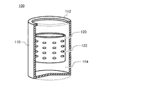
- FIG. 2 is a partial cross-sectional view showing a reaction vessel used for UC processing.
- the reactor 100 shown in FIG. 2 is configured to include an outer cylinder 110 having a claw plate 112 at an opening, and an inner cylinder 120 having a through hole 122 and rotating. The reactant is introduced into the inner cylinder 120 of the reactor 100.
- the introduced reactant collides with the inner wall 114 of the outer cylinder 110 through the through hole 122 of the inner cylinder 120 due to the centrifugal force generated by turning the inner cylinder 120. Due to this collision, the reaction product becomes a thin film and slides up to the upper portion of the inner wall 114. In this state, both the shear stress between the inner wall 114 and the centrifugal force from the inner cylinder 120 are simultaneously applied to the reactant. That is, a large mechanical energy is applied to the reactant by the reactor 100. It is considered that this mechanical energy is converted into chemical energy necessary for the reaction, so-called activation energy. Thereby, reaction advances in a short time. To impart sufficient mechanical energy to reactants is preferably to generate a 1500 N (kgms -2) or more centrifugal force, it is more preferable to generate a centrifugal force of more than 60000N (kgms -2).
- UC process is executed in two processes.
- a shear stress and a centrifugal force are applied to the vanadium source, the aluminum source, and the conductive carbon material to adhere the vanadium source and the aluminum source to the conductive carbon material.
- shear stress and centrifugal force are applied to a lithium source, a phosphate source, and vanadium in which aluminum formed on the surface of the conductive carbon material is dissolved, so that the aluminum is solidified.
- Lithium vanadium phosphate can be produced on the basis of dissolved vanadium.
- the positive electrode material is dispersed in the form of particles using the Pecini method, and an aluminum solid solution vanadium oxide composite bonded to the surface of the conductive carbon material is obtained.
- the manufacturing method mixes so that the range of the number-of-moles of aluminum in an aluminum source may be more than 0 and 0.33 or less with respect to 1 mol of vanadium in a vanadium source. Water is added to this mixture to form an aqueous solution containing vanadium ions and aluminum ions, and an organic compound having a plurality of carboxyl groups is added to form a metal complex.
- the polymer is polymerized by an ester reaction between the metal complex and an alcohol having a plurality of hydroxyl groups.
- the mixture is subjected to UC treatment by adding a conductive carbon material, dried, and fired, and then subjected to a first treatment to disperse the particles in the form of a solid solution of vanadium oxide composite dissolved in aluminum bonded to the surface of the conductive carbon material.
- the body was obtained.
- the reason why the vanadium oxide composite dispersed in the particle shape is thus obtained is that the polymer formed by the polymerization reaction serves as a spacer that enters between the metal complexes. It is thought that it was maintained in a distributed state.
- vanadium sources examples include NH 4 VO 3 , V 2 O 5 , V 2 O 3 , metal vanadium, V 2 O 4 , vanadium (III) acetylacetonate and vanadium (IV) oxyacetylacetonate. May be.
- the aluminum source examples include Al (NO 3 ) 3, but metal aluminum, alumina, and other inorganic acid salts and organic acid salts of aluminum may be used.
- lithium source examples include CH 3 COOLi, but LiNO 3 , Li 2 CO 3 , LiOH, LiOH.H 2 O, LiCl, Li 2 SO 4, and LIC 3 H 5 O 3 may be used.
- the phosphoric acid source includes H 3 PO 4, but may be a PO 4 -containing compound such as NH 4 H 2 PO 4 , (NH 4 ) 2 HPO 4 , P 2 O 5 and Li 3 PO 4. .
- carbon nanofibers and conductive carbon black having a hollow shell structure are suitable, but carbon black such as carbon nanotubes and acetylene black, Amorphous carbon, carbon fiber, natural graphite, artificial graphite, activated carbon, mesoporous carbon, or a mixture of these can also be applied.
- Examples of the organic compound having a plurality of carboxyl groups include tricarboxylic acid citric acid, but dicarboxylic acids such as oxalic acid, malonic acid, and succinic acid may also be used.
- Examples of the alcohol having a plurality of hydroxyl groups include ethylene glycol, but other divalent alcohols such as propylene glycol or trivalent alcohols such as glycerin may be used.
- the lithium secondary battery 10 obtains an effect of excellent discharge capacity, particularly high discharge capacity characteristics at a high C rate, and excellent deterioration resistance due to the positive electrode material included in the positive electrode 18. .
- the positive electrode material of this embodiment is applicable also to the electrode of a capacitor.
- Example 1 a positive electrode material composed of a composite of lithium vanadium phosphate and carbon nanofiber (hereinafter sometimes referred to as CNF) in which aluminum at a molar ratio of 10% is dissolved is produced by the manufacturing procedure shown below. did.
- CNF lithium vanadium phosphate and carbon nanofiber
- Material source of lithium vanadium phosphate is ammonium metavanadate (NH 4 VO 3), aluminum nitrate hydrate (Al (NO 3) 3 ⁇ 9H 2 O), lithium acetate (LiOAc), phosphoric acid (H 3 PO 4 ).
- the average fiber diameter of CNF is 10 to 20 nm.
- the weight ratio of each material source of lithium vanadium phosphate and CNF is 70:30.
- FIG. 3 is a flowchart showing a manufacturing procedure of the first treatment of the lithium vanadium phosphate composite in which aluminum is dissolved.
- a metal complex is formed by vanadium ions and aluminum ions and citric acid, and citric acid forms a polymer by an ester reaction with ethylene glycol.
- the polymer formed by the polymerization reaction penetrates between the metal complexes, thereby dispersing the metal complex and maintaining the dispersion state.
- This mixed solution was subjected to UC treatment in an environment of 80 ° C. using the reactor shown in FIG.
- the inner cylinder 120 was rotated at a rotational speed of 50 m / s, and a centrifugal force of 66000 N (kgms ⁇ 2 ) was applied to the mixed solution for 5 minutes.
- the metal complex is made finer and highly dispersed, the CNF is dissolved, and the binding of the metal complex to the CNF surface is promoted.
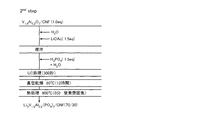
- FIG. 4 is a flowchart showing the manufacturing procedure of the second treatment of the lithium vanadium phosphate composite in which aluminum is dissolved.
- a solution in which aluminum is dissolved but vanadium oxide (V 1.8 Al 0.2 O 3 ) and CNF are present in an amount of 1.0 equivalent is used for distilled water and lithium acetate ( LiOAc) 1.5 equivalents was added and stirred, and distilled water and 1.5 equivalents of phosphoric acid (H 3 PO 4 ) were further added, and UC treatment was performed at a rotational speed of 50 m / s for 5 minutes.
- LiOAc lithium acetate
- H 3 PO 4 phosphoric acid
- the obtained mixed solution was vacuum-dried at 80 ° C. for 12 hours in a vacuum, and then baked at 900 ° C. for 0 minute in a nitrogen atmosphere.
- the temperature is raised from room temperature to 900 ° C. in 3 minutes, and then naturally cooled.
- rapid heating is considered to prevent aggregation of lithium vanadium phosphate and maintain nanoparticles having a small particle size.
- the rapid heating is desirably performed in an atmosphere having a low oxygen concentration with an oxygen concentration of about 1000 ppm. Thereby, the oxidation of CNF can be prevented.
- the solid solution amount of aluminum is determined by the mixing ratio of ammonium metavanadate and aluminum nitrate in the mixed solution used in the first treatment. That is, in the example shown in FIG. 3, since 0.1 equivalent of aluminum nitrate is mixed with 0.9 equivalent of ammonium metavanadate, V 1.8 Al 0.2 O 3 is generated. Therefore, for example, when 0.05 equivalent of aluminum nitrate is mixed with 0.95 equivalent of ammonium metavanadate, V 1.9 Al 0.1 O 3 is generated. By executing the second process using the V 1.9 Al 0.1 O 3, complex powder Li 3 V 1.9 Al 0.1 (PO 4) 3 is supported on CNF is can get.
- FIG. 5 shows an XRD profile of the vanadium oxide composite in which aluminum obtained by the first treatment is dissolved.
- a peak is observed at the same position as the XRD profile of vanadium oxide (V 2 O 3 ) of ICDD. It has been confirmed that dissolved vanadium oxide (V 1.8 Al 0.2 O 3 ) has the same crystal structure as vanadium oxide (V 2 O 3 ) and no impurities are formed.
- FIG. 6 shows an EDX plane analysis result of lithium vanadium phosphate in which aluminum obtained by the second treatment is dissolved.
- the colored region in the figure shows the distribution state of O, P, C, V, and Al. From FIG. 6, it can be observed that O, P, and V indicating lithium vanadium phosphate and Al are similarly dispersed. In this way, in the lithium vanadium phosphate in which the aluminum obtained by the first treatment and the second treatment is solid-dissolved, the aluminum is dispersed almost uniformly without being unevenly distributed in the vanadium phosphate, and the solid solution I understand that.
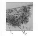
- FIG. 7 is an HRTEM image of a lithium vanadium phosphate composite that is bonded to the CNF surface and in which aluminum is dissolved.
- the arrows indicate lithium vanadium phosphate particles in which aluminum is dissolved, and the rod-shaped substance is CNF.
- FIG. 7 it can be observed that lithium vanadium phosphate in which aluminum is dissolved is dispersed in a particle shape of 10 nm to 100 nm.
- an image focused on the particle and CNF is obtained, it can be confirmed that the particle and CNF are at the same height. From this, the particle is bonded to the surface of CNF. You can see that Thus, it can be seen from FIG. 7 that lithium vanadium phosphate in which aluminum is dissolved is present in a state of being bonded to the surface of CNF in a particle shape of 10 nm to 100 nm.
- FIG. 8 shows the HRTEM image and particle size distribution of lithium vanadium phosphate.
- 8A shows V 2 O 3 / CNF
- (b) shows V 1.8 Al 0.2 O 3 / CNF
- (c) shows Li 3 V 2 (PO 4 ) 3 / CNF
- ( d) shows an HRTEM image and a particle size distribution of a complex of Li 3 V 1.8 Al 0.2 (PO 4 ) 3 / CNF.
- the particle size of the lithium vanadium phosphate supported on the CNF is obtained by measuring the particle size of the lithium vanadium phosphate image particles in the HRTEM image. Further, the number of particles is also obtained by counting the number of lithium vanadium phosphate in the HRTEM image.
- the particle size distribution shown in FIG. 8 is created from the particle size measured from the HRTEM image and the number of counted particles.
- This composite powder was put into a SUS mesh welded on a SUS plate together with polyvinylidene fluoride PVDF as a binder, and the working electrode W.P. E. It was.
- a Li foil was placed as a reference electrode.
- the electrolyte was 1.0 M lithium hexafluorophosphate (LiPF 6 ) / ethylene carbonate (EC) and dimethyl carbonate (DEC), and these were infiltrated into a cell.
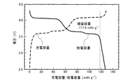
- FIG. 9 is a graph showing charge / discharge characteristics of a positive electrode material containing lithium vanadium phosphate in which aluminum is dissolved.
- the horizontal axis indicates the discharge capacity
- the vertical axis indicates the potential.
- the charge capacity was calculated as the theoretical capacity decreased by the amount of aluminum added.
- the theoretical capacity of 117.9 mAhg ⁇ 1 was slightly increased to 126 mAhg ⁇ 1 , and the capacity expression rate was 107%.
- FIG. 10 shows the first treatment in the production method of the lithium vanadium phosphate composite of Reference Example 1 by the alkali coagulation precipitation method.
- CNF and vanadium (III) chloride were added to distilled water (H 2 O), and the mixture was subjected to UC treatment.
- the UC process is performed for 2 minutes.
- impurities were filtered from the solution, vacuum-dried at 80 ° C., and then baked at 800 ° C. for 5 minutes in a nitrogen atmosphere. By this calcination, a dehydration condensation reaction occurred in vanadium (III) hydroxide to form vanadium (III) oxide (V 2 O 3 ) bonded to the surface of CNF.
- FIG. 11 shows a second treatment in the production method of the lithium vanadium phosphate composite of Reference Example 1 by the alkali coagulation precipitation method.
- 1.5 equivalents of distilled water and lithium acetate (LiOAc) were added to a solution containing 1.0 equivalent of a conjugate of vanadium (III) oxide (V 2 O 3 ) and CNF.
- the mixture was further stirred, and 1.5 equivalents of distilled water and phosphoric acid (H 3 PO 4 ) were added to carry out UC treatment for 5 minutes.
- the obtained solution was dried in a vacuum at 80 ° C. overnight and then baked in a nitrogen atmosphere at 800 ° C. for 5 minutes. By this firing, crystallization of lithium vanadium phosphate proceeds, and a composite powder in which lithium vanadium phosphate is bonded to CNF is obtained.
- FIG. 12 is an HRTEM image showing an overall image of lithium vanadium phosphate produced by the alkali coagulation precipitation method.
- FIG. 13 is an HRTEM image showing a partially enlarged view of lithium vanadium phosphate produced by an alkali coagulation precipitation method. As shown in FIG. 12 and FIG. 13, lithium vanadium phosphate produced by the alkali coagulation precipitation method has a mixture of 50 to 500 nm plate-shaped crystals and 3 to 6 nm particle-shaped crystals mixed with CNF. Yes.
- This composite powder was put into a SUS mesh welded on a SUS plate together with polyvinylidene fluoride PVDF as a binder, and the working electrode W.P. E. It was.
- a Li foil was placed as a reference electrode.
- the electrolyte was 1.0 M lithium hexafluorophosphate (LiPF 6 ) / ethylene carbonate (EC) and dimethyl carbonate (DEC), and these were infiltrated into a cell.
- FIG. 14 shows the discharge rate characteristics.
- the horizontal axis represents the C rate
- the vertical axis represents the discharge capacity.
- the discharge rate characteristics reported so far are listed on the graph.
- the positive electrode material made of a composite of lithium vanadium phosphate and CNF in which aluminum is solid-dissolved has a discharge capacity of 85 mAhg ⁇ 1 at a high C rate of 480 C.
- Rui, et al. C-rate discharge capacity and L. This is much better than the discharge capacity at the C rate reported by Zhang, et al.
- the positive electrode material according to the reference example had a discharge capacity at 480 C of 80 mAhg ⁇ 1 , and the positive electrode material shown in the example could secure a higher discharge capacity than that of the reference example 1.
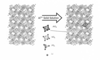
- FIG. 15 is a schematic diagram showing a crystal structure of lithium vanadium phosphate in which aluminum is dissolved.
- the left side of the drawing shows the crystal structure of lithium vanadium phosphate
- the right side of the drawing shows the crystal structure of lithium vanadium phosphate containing aluminum.
- the lithium vanadium phosphate has a NASICON structure in which the VO 6 octahedron and the PO 4 tetrahedron share a vertex and are arranged three-dimensionally.
- Lithium vanadium phosphate in which aluminum is solid-solved partially includes an AlO 6 octahedron in which aluminum is substituted at the site of vanadium atoms, and has a NASICON structure similar to lithium vanadium phosphate.
- Lithium vanadium phosphate in which aluminum is dissolved is represented by the general formula Li 3 V (2-x) Al x (PO 4 ) 3 , and x is 0 ⁇ x ⁇ 0.5.
- the valence of vanadium changes from trivalent to tetravalent or pentavalent due to the desorption of lithium ions accompanying charging and discharging.
- dissolved aluminum does not participate in the electrochemical reaction. Therefore, even if lithium ion desorption / insertion associated with charge / discharge occurs, the valence of aluminum remains trivalent.
- lithium vanadium phosphate In the crystal structure of lithium vanadium phosphate, it is considered that the valence of vanadium changes due to desorption / insertion of lithium ions accompanying charging and discharging of the secondary battery, and the crystal structure of lithium vanadium phosphate contracts or expands. It is considered that the diffusion rate of lithium ions is slowed by the volume change of the crystal structure accompanying the desorption of lithium ions. Thereby, it can be estimated that the discharge capacity at the high C rate has decreased.
- the crystal structure of vanadium phosphate in which aluminum is dissolved does not change the valence of aluminum due to the lithium insertion and removal. Conceivable.
- the crystal structure of vanadium phosphate which contains part of the crystal structure that does not cause volume change, is the volume change of aluminum in other crystal structures even when lithium desorption occurs due to charge / discharge of the secondary battery. It is thought that it suppresses.
- lithium vanadium phosphate in which aluminum is solid-solubilized can be increased in lithium ion diffusion rate than lithium vanadium phosphate in which aluminum is not solid-solubilized, and discharge capacity characteristics at a high C rate are enhanced. it can.
- FIG. 16 is a table showing changes in the lattice parameters of the positive electrode material before and after charging and discharging, and changes in volume calculated from the lattice parameters.
- the XRD measurement of the positive electrode material before and after charge and discharge was performed, and the change in the lattice parameters and the volume change (Volume Strain) were calculated.
- the volume change of the lithium vanadium phosphate in Reference Example 1 was 6.4%.
- the volume change of lithium vanadium phosphate in which aluminum was solid-dissolved was 4.4%. As described above, it has been confirmed that the volume change of the crystal structure due to lithium desorption / insertion associated with charging / discharging of the secondary battery can be suppressed by dissolving aluminum in solid solution.
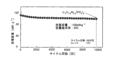
- FIG. 17 is a graph showing the discharge cycle characteristics.
- FIG. 17 shows the discharge cycle characteristics of the positive electrode material containing lithium vanadium phosphate in which aluminum is dissolved.
- the horizontal axis indicates the number of cycles, and the vertical axis indicates the discharge capacity.
- the positive electrode material containing lithium vanadium phosphate in which aluminum is solid-solved maintains a discharge capacity of 100 mAhg ⁇ 1 even after 9500 cycles of charge and discharge at a discharge rate of 10 C. The capacity retention rate was 89%. This shows that the positive electrode material containing lithium vanadium phosphate is excellent in deterioration resistance.
- Example 2 In Example 2, 0.05 equivalent of aluminum nitrate was mixed with 0.95 equivalent of ammonium metavanadate in the mixed solution used in the first treatment, and lithium vanadium phosphate (LiV 1) in which 5% of aluminum was dissolved. .9 A positive electrode material made of a composite powder of Al 0.1 (PO 4 ) 3 ) and carbon nanofibers was produced.
- the working electrode W.P. E. And created a cell.
- This cell is set to a working voltage of 2.5 to 4.3 V and a discharge rate of 1 C.
- the charge / discharge characteristics were examined in C mode (constant current mode).
- FIG. 18 shows the charge / discharge characteristics of a positive electrode material containing a lithium vanadium phosphate composite.
- FIG. 18 shows charge / discharge characteristics of a cell having a positive electrode material containing lithium vanadium phosphate in which 5% of aluminum was dissolved in Example 2 and charging / discharging of a cell having a positive electrode material containing lithium vanadium phosphate in Reference Example 1. The discharge characteristics are shown.
- the horizontal axis indicates the discharge capacity
- the vertical axis indicates the potential.
- Discharge capacity of the positive electrode material of 5% aluminum containing lithium vanadium phosphate dissolved is the theoretical capacity 125MAhg -1 calculated as the theoretical capacity by the amount of addition of aluminum is decreased, 123MAhg -1 becomes decreased slightly, The capacity expression rate was 95.2%.
- the discharge capacity of the positive electrode material containing lithium vanadium phosphate of Reference Example 1 was slightly reduced to 123 mAhg ⁇ 1 from the theoretical capacity of 131 mAhg ⁇ 1 , and the capacity expression rate was 90.8%.
- the positive electrode material containing lithium vanadium phosphate in which 5% of aluminum was solid-solved showed a higher capacity development rate than the positive electrode material containing lithium vanadium phosphate in which aluminum was not solid-dissolved.
- FIG. 19 shows the charge rate characteristics.
- FIG. 19 shows the charge rate characteristics of a positive electrode material containing lithium vanadium phosphate in which 5% aluminum is dissolved, and the charge rate characteristics of a positive electrode material containing lithium vanadium phosphate.
- the horizontal axis indicates the C rate
- the vertical axis indicates the charge capacity.
- the positive electrode material containing lithium vanadium phosphate in which 5% of aluminum was solid-solved exhibited a higher charge capacity than the positive electrode material containing lithium vanadium phosphate at a high C rate of 50 to 480 C. .
- the positive electrode material containing lithium vanadium phosphate in which 5% aluminum is solid-dissolved has higher charge capacity characteristics at a high C rate than the positive electrode material containing lithium vanadium phosphate in which aluminum is not solid-dissolved.
- FIG. 20 shows the discharge rate characteristics.
- FIG. 20 shows the discharge rate characteristics of a positive electrode material containing lithium vanadium phosphate in which 5% of aluminum is dissolved, and the discharge rate characteristics of a positive electrode material containing lithium vanadium phosphate.
- the horizontal axis indicates the C rate
- the vertical axis indicates the discharge capacity.
- the positive electrode material containing lithium vanadium phosphate in which 5% of aluminum is solid-solved exhibited a higher discharge capacity than the positive electrode material containing lithium vanadium phosphate at a high C rate of 50 to 480 C.
- the positive electrode material containing lithium vanadium phosphate in which 5% aluminum is solid-dissolved has higher discharge capacity characteristics at a high C rate than the positive electrode material containing lithium vanadium phosphate in which aluminum is not solid-dissolved.
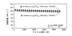
- FIG. 21 shows the cycle characteristics of discharge.
- FIG. 21 shows the cycle characteristics of a positive electrode material containing lithium vanadium phosphate in which 5% of aluminum is dissolved, and the cycle characteristics of a positive electrode material containing lithium vanadium phosphate.
- the horizontal axis indicates the number of cycles, and the vertical axis indicates the discharge capacity.
- the positive electrode material containing lithium vanadium phosphate in which 5% of aluminum is dissolved is maintained at a discharge capacity of 100 mAhg ⁇ 1 after 4500 cycles of charge and discharge at a discharge rate of 10C.
- the capacity retention rate was 92.4%.
- the positive electrode material containing lithium vanadium phosphate maintained a discharge capacity of 96 mAhg ⁇ 1 after 4500 cycles of charge and discharge at a discharge rate of 10 C, and the capacity retention rate was 89.4%.
- the positive electrode material containing lithium vanadium phosphate in which 5% of aluminum is solid-dissolved is superior in deterioration resistance to the positive electrode material containing lithium vanadium phosphate in which aluminum is not solid-dissolved. Recognize.
- the positive electrode material containing lithium vanadium phosphate in which 5% aluminum is solid-dissolved has a higher capacity development rate and charge rate characteristics than the positive electrode material containing lithium vanadium phosphate in which aluminum is not solid-dissolved. Excellent discharge rate characteristics and deterioration resistance.
- aluminum in lithium vanadium phosphate has a solid solution amount of 5%, aluminum can suppress the volume change of the crystal structure of vanadium phosphate due to desorption of lithium and can stabilize the crystal structure. .
- the positive electrode material containing lithium vanadium phosphate in which 5% of aluminum was dissolved was excellent in capacity development rate, charge rate characteristics, discharge rate characteristics, and deterioration resistance.
- LiV 1.9 M 0.1 O 3, M Ga
- FIG. 22 is a flowchart showing the manufacturing procedure of the first treatment of the lithium vanadium phosphate composite in which gallium or indium is dissolved.
- 0.95 equivalent of ammonium metavanadate (NH 4 VO 3 ), 1.0 equivalent of citric acid, 4.0 equivalent of ethylene glycol, 0.05 equivalent of gallium nitrate or 0.05 equivalent of indium nitrate A mixed solution was prepared by adding an equivalent amount and CNF to distilled water (H 2 O). Next, the prepared mixed solution was subjected to UC treatment in an environment of 80 ° C. As the UC treatment, the inner cylinder 120 was rotated at a rotational speed of 50 m / s, and a centrifugal force of 66000 N (kgms ⁇ 2 ) was applied to the mixed solution for 5 minutes.
- the working electrode W.P. E. Using the composite powder obtained by the above treatment, the working electrode W.P. E. And created a cell. This cell is set to a working voltage of 2.5 to 4.3 V and a discharge rate of 1 C. The charge / discharge characteristics were examined in C mode (constant current mode).
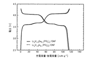
- FIG. 23 shows the charge / discharge characteristics.
- FIG. 23 shows charge / discharge characteristics of a positive electrode material containing lithium vanadium phosphate in which gallium is dissolved, and charge / discharge characteristics of a positive electrode material containing lithium vanadium phosphate in which indium is dissolved.
- the vertical axis indicates the potential
- the horizontal axis indicates the discharge capacity.
- FIG. 24 shows the discharge rate characteristics.
- FIG. 24 shows discharge rate characteristics of a positive electrode material containing lithium vanadium phosphate in which gallium is dissolved, lithium vanadium phosphate in which indium is dissolved, and lithium vanadium phosphate.
- the horizontal axis represents the C rate
- the vertical axis represents the discharge capacity.
- the discharge capacity of the positive electrode material containing lithium vanadium phosphate in which gallium is dissolved is lower than that of the positive electrode material containing lithium vanadium phosphate at a C rate as low as 1C. This is because the theoretical capacity is reduced by dissolving gallium which is not involved in the electrochemical reaction.
- the discharge capacity of the positive electrode material containing lithium vanadium phosphate in which gallium is dissolved is higher than that of the positive electrode material containing lithium vanadium phosphate.
- the positive electrode material containing lithium vanadium oxide in which gallium is dissolved has high discharge capacity characteristics at a high C rate.
- the discharge capacity of the positive electrode material containing lithium vanadium phosphate in which indium is dissolved is lower than the positive electrode material containing lithium vanadium phosphate at a C rate as low as 1C.
- the discharge capacity of the positive electrode material containing lithium vanadium phosphate in which indium is dissolved is higher than that of the positive electrode material containing lithium vanadium phosphate.
- FIG. 25 shows the charge rate characteristics.
- FIG. 25 shows the charge rate characteristics of a positive electrode material containing lithium vanadium phosphate in which gallium is dissolved, lithium vanadium phosphate in which indium is dissolved, and lithium vanadium phosphate.
- the horizontal axis indicates the C rate
- the vertical axis indicates the charge capacity. From FIG. 25, the charge capacity of the positive electrode material containing lithium vanadium phosphate in which gallium is dissolved is lower than that of the positive electrode material containing lithium vanadium phosphate at a C rate as low as 1C. However, at a high C rate of 480 C, the charge capacity of the positive electrode material containing lithium vanadium phosphate in which gallium is dissolved is higher than that of the positive electrode material containing lithium vanadium phosphate. Thus, it can be seen that the positive electrode material containing lithium vanadium oxide in which gallium is solid-solved can obtain high charge capacity characteristics at a high C rate.
- the charge capacity of the positive electrode material containing lithium vanadium phosphate in which indium is dissolved is lower than that of the positive electrode material containing lithium vanadium phosphate at a C rate as low as 1C.
- the charge capacity of the positive electrode material containing lithium vanadium phosphate in which indium is dissolved is higher than that of the positive electrode material containing lithium vanadium phosphate.
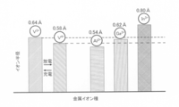
- FIG. 26 is a diagram illustrating the ion radius of metal ions.
- the height of the bar graph indicates the size of the ion radius. That is, a high bar graph indicates that the ionic radius is large, and a low bar graph indicates that the ionic radius is small.
- the ionic radius of aluminum dissolved in vanadium is 0.54 ⁇ ⁇ ⁇ . Further, the ionic radius of gallium dissolved in vanadium is 0.62 ⁇ , and the ionic radius of indium is 0.80 ⁇ .
- the ionic radius of trivalent vanadium is larger than the ionic radius of aluminum having a small ionic radius, gallium having an ionic radius almost the same as that of trivalent vanadium, and trivalent vanadium. Any of the indium contained can be improved in capacity characteristics at a high C rate of the positive electrode material containing the metal by being dissolved in vanadium.
- the metal solid-dissolved in vanadium is a metal that has the same trivalence as the vanadium ion and does not change in valence due to lithium ion desorption, but the ionic radius of the metal is small or large. Regardless, the capacity characteristics under high C rate conditions can be improved.
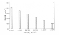
- FIG. 27 is a graph showing the theoretical capacity of lithium vanadium phosphate in which aluminum is dissolved. Since aluminum does not participate in the electrochemical reaction, the theoretical capacity of the positive electrode material was calculated on the assumption that the theoretical capacity is reduced by the amount of aluminum added. As shown in FIG. 27, by setting the upper limit of the solid solution amount of aluminum to 25% or less, lithium vanadium phosphate in which aluminum is solid solution can secure a theoretical capacity of 100 mAhg ⁇ 1 or more.
- lithium vanadium phosphate in which aluminum is dissolved is represented by the general formula Li 3 V (2-x) Al x (PO 4 ) 3
- x is preferably 0 ⁇ x ⁇ 0.5.
- the theoretical capacity decreases, but by setting x to 0.5 or less, the upper limit of the solid solution amount of aluminum can be 25% or less. As a result, the theoretical capacity of lithium vanadium phosphate in which aluminum is dissolved is 100 mAhg ⁇ 1 or more.
- lithium vanadium phosphate in which aluminum or the like is dissolved is shown, but aluminum or the like may not be dissolved.
- Lithium vanadium phosphate in which aluminum is not dissolved is manufactured using the Pecini method as in the present example, but does not include aluminum nitrate, which is an aluminum source.
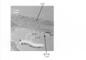
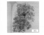
- FIG. 28 is an HRTEM image of a lithium vanadium phosphate composite in which aluminum produced by the Pecini method is not dissolved.
- the black portion indicates a lithium vanadium phosphate complex
- the light gray portion indicates CNF.
- the lithium vanadium phosphate shown in the manufacturing method shown in this example is dispersed in a crystal having a particle shape of 10 nm to 200 nm, and is bonded to CNF.
- the lithium vanadium phosphate composite in which aluminum is not solid-dissolved is dispersed in a particle shape of 10 nm to 200 nm and bonded to CNF, and this dispersed state has a high discharge capacity characteristic at a high C rate. And brings about deterioration resistance characteristics.
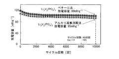
- FIG. 29 shows the cycle characteristics of discharge.
- FIG. 29 shows the cycle characteristics of the discharge of the lithium vanadium phosphate composite in which aluminum produced by the Pecini method is not dissolved.
- the positive electrode material composed of a lithium vanadium phosphate composite in which crystals having a particle shape of 10 nm to 200 nm manufactured by the Pecini method are dispersed is discharged even after 9500 cycles of charge / discharge. A capacity of 99 mAhg ⁇ 1 could be maintained.
- the positive electrode material composed of the lithium vanadium phosphate composite produced by the alkali coagulation precipitation method shown in Reference Example 1 had a discharge capacity of 95 mAhg ⁇ 1 after 9500 cycles of charge and discharge.
- a positive electrode material composed of a lithium vanadium phosphate composite in which crystals having a particle shape of 10 nm to 200 nm are dispersed can maintain a higher discharge capacity and is excellent in deterioration resistance.
- the alkali coagulation precipitation method shown in Reference Example 1 uses VCl 3 that generates chlorine or hydrogen chloride by decomposition of vanadium chloride or NaOH that gives irreversible capacity by damaging the surface of the conductive carbon material.
- the manufacturing method shown in Example 1 is a manufacturing method that is more environmentally friendly because no VCl 3 is used, and thus no chlorine or hydrogen chloride is generated.
- it can manufacture without adding NaOH, the surface of a conductive carbon material is not damaged. Thereby, an increase in the initial irreversible capacity can be suppressed, and good deterioration resistance can be achieved.
- the conductive carbon material is not limited to CNF, and may be Ketjen Black (registered trademark).
- Ketjen Black (registered trademark) is a conductive carbon black having a hollow shell-like structure and is suitable as a conductive carbon material like CNF.
- lithium secondary battery 12 battery case (housing), 14 ion conductor, 16 separator, 18 positive electrode, 20 negative electrode, 22 positive electrode terminal, 24 negative electrode terminal, 26 load, 100 reactor, 110 outer cylinder, 112 dam plate, 114 inner wall, 120 inner cylinder, 122 through hole
Landscapes
- Chemical & Material Sciences (AREA)
- Chemical Kinetics & Catalysis (AREA)
- Electrochemistry (AREA)
- General Chemical & Material Sciences (AREA)
- Composite Materials (AREA)
- Inorganic Chemistry (AREA)
- Engineering & Computer Science (AREA)
- Materials Engineering (AREA)
- Crystallography & Structural Chemistry (AREA)
- Battery Electrode And Active Subsutance (AREA)
Abstract
Description
非特許文献1 X.Rui,et al., J. PowerSources, 214, 171 (2012)
非特許文献2 L.Zhang, et al., J. Power Sources, 203, 121 (2012)
非特許文献3 A.Pan et al., 「Nano-structured Li3V2(PO4)3/carbon composite forhigh-rate lithium-ion batteries」,Electrochemistry Communications, 12, 1674-1677(2010)
本実施例1では、下記に示す製造手順により、モル比で10%のアルミニウムが固溶したリン酸バナジウムリチウムとカーボンナノファイバ(以後、CNFという場合がある)の複合体からなる正極材料を生成した。
図10は、参考例1のリン酸バナジウムリチウム複合体のアルカリ凝集沈殿法による製造方法における第1の処理を示す。図10に示すように、まず、CNFと塩化バナジウム(III)を蒸留水(H2O)に加え、混合液をUC処理した。次に、水酸化ナトリウム(NaOH)を加えて混合液をpH=7に調整することで、塩化バナジウム(III)を加水分解し、水酸化バナジウム(III)(V(OH)3)を生成した。このとき、UC処理を2分間行う。そして、溶液から不純物を濾過し、80℃で真空乾燥した後、窒素雰囲気中、800℃で5分間焼成した。この焼成で、水酸化バナジウム(III)に脱水縮合反応が生じ、CNFの表面に結合した酸化バナジウム(III)(V2O3)を形成した。
本実施例2では、第1の処理で使用した混合溶液におけるメタバナジン酸アンモニウム0.95当量に対し硝酸アルミニウム0.05当量混合させて、5%のアルミニウムが固溶したリン酸バナジウムリチウム(LiV1.9Al0.1(PO4)3)とカーボンナノファイバの複合体粉末からなる正極材料を生成した。
本実施例3では、アルミニウムに代えて、リチウムの脱挿入により価数の変化しない金属としてガリウムまたはインジウムを固溶させたリン酸バナジウムリチウム(LiV1.9M0.1O3、M=Ga、In)とカーボンナノファイバの複合体粉末からなる正極材料を生成した。
Claims (14)
- リチウムイオンの脱挿入により3価から5価の間で価数が変化するバナジウムを含むリン酸バナジウムリチウムと、
導電性炭素材料と、
を含み、
前記リン酸バナジウムリチウムは、前記導電性炭素材料の表面に結合しており、
前記リン酸バナジウムリチウムにおける全重量の90%以上は、直径が10から200nmの粒子形状の結晶体である正極材料。 - 前記リン酸バナジウムリチウムの直径は、10から100nmである請求項1に記載の正極材料。
- 前記導電性炭素材料は、カーボンナノファイバである請求項1または2に記載の正極材料。
- 前記導電性炭素材料は、中空シェル状の構造を有する導電性カーボンブラックである請求項1から3の何れか1項に記載の正極材料。
- 前記リン酸バナジウムリチウムは、さらにアルミニウムを含み、
前記アルミニウムは、前記リン酸バナジウムリチウムに固溶している請求項1から4の何れか1項に記載の正極材料。 - 前記アルミニウムを含む前記リン酸バナジウムリチウムは、一般式LiV2―xAlx(PO4)3で表され、xは0<x≦0.5である請求項5に記載の正極材料。
- 請求項1から6の何れか1項に記載の前記正極材料を含む正極と、負極と、イオン伝導体と、セパレータとを有する二次電池。
- バナジウム源と、
導電性炭素材料と、
複数のカルボキシル基を有する有機化合物と、
複数の水酸基を有するアルコールと、
を含む混合物の水溶液を、旋回する反応容器内でずり応力と遠心力を加えて、酸化バナジウムを導電性炭素材料の表面に結合させるステップを含む第1の処理と、
前記混合物にリン酸源とリチウム源とを加えて、旋回する反応容器内でずり応力と遠心力を加えて、前記導電性炭素材料の表面に粒子形状で結合したリン酸バナジウムリチウムを生成するステップを含む第2の処理と、
を含む正極材料の製造方法。 - 前記第1の処理は、酸化バナジウムを導電性炭素材料の表面に結合させるステップに続いて、
前記混合物を乾燥するステップと、
前記混合物を焼成するステップと、
をさらに含む請求項8に記載の正極材料の製造方法。 - 前記混合物を乾燥するステップは、
前記複数のカルボキシル基を有する有機化合物と、
前記複数の水酸基を有するアルコールと、
前記複数のカルボキシル基を有する有機化合物と前記複数の水酸基を有するアルコールとのエステル化反応により生成する有機化合物と、
を蒸発させるステップをさらに含む請求項9に記載の正極材料の製造方法。 - 前記第2の処理は、前記導電性炭素材料の表面に粒子形状で結合したリン酸バナジウムリチウムを生成するステップに続いて、
前記リン酸バナジウムリチウムを乾燥するステップと、
前記リン酸バナジウムリチウムを焼成するステップと、
をさらに含む請求項8から10の何れか1項に記載の正極材料の製造方法。 - 酸化バナジウムを導電性炭素材料の表面に結合させるステップにおける混合物は、さらにアルミニウム源を含む請求項8から11の何れか1項に記載の正極材料の製造方法。
- バナジウム源とアルミニウム源は、バナジウム源におけるバナジウム1モルに対して、アルミニウム源におけるアルミニウムのモル数の範囲が0より多く0.33以下となるように混合する請求項8から12の何れか1項に記載の正極材料の製造方法。
- 請求項8から13の何れか1項に記載の正極材料の製造方法を含む、二次電池の製造方法。
Priority Applications (3)
| Application Number | Priority Date | Filing Date | Title |
|---|---|---|---|
| EP15795693.9A EP3147975B1 (en) | 2014-05-23 | 2015-05-22 | Positive electrode material, secondary battery, method for manufacturing positive electrode material, and method for manufacturing secondary battery |
| CN201580037607.XA CN106575767B (zh) | 2014-05-23 | 2015-05-22 | 正极材料、二次电池、正极材料的制造方法及二次电池的制造方法 |
| JP2016521160A JP6650871B2 (ja) | 2014-05-23 | 2015-05-22 | 正極材料、二次電池、正極材料の製造方法および二次電池の製造方法 |
Applications Claiming Priority (2)
| Application Number | Priority Date | Filing Date | Title |
|---|---|---|---|
| JP2014107342 | 2014-05-23 | ||
| JP2014-107342 | 2014-05-23 |
Publications (1)
| Publication Number | Publication Date |
|---|---|
| WO2015178479A1 true WO2015178479A1 (ja) | 2015-11-26 |
Family
ID=54554138
Family Applications (1)
| Application Number | Title | Priority Date | Filing Date |
|---|---|---|---|
| PCT/JP2015/064730 Ceased WO2015178479A1 (ja) | 2014-05-23 | 2015-05-22 | 正極材料、二次電池、正極材料の製造方法および二次電池の製造方法 |
Country Status (4)
| Country | Link |
|---|---|
| EP (1) | EP3147975B1 (ja) |
| JP (1) | JP6650871B2 (ja) |
| CN (1) | CN106575767B (ja) |
| WO (1) | WO2015178479A1 (ja) |
Cited By (4)
| Publication number | Priority date | Publication date | Assignee | Title |
|---|---|---|---|---|
| CN106328943A (zh) * | 2016-11-11 | 2017-01-11 | 攀钢集团攀枝花钢铁研究院有限公司 | 一种制备锂离子电池正极材料磷酸钒锂的方法 |
| CN106410193A (zh) * | 2016-11-11 | 2017-02-15 | 攀钢集团攀枝花钢铁研究院有限公司 | 制备钠离子电池用正极材料磷酸钒钠及磷酸钒的方法 |
| CN112233911A (zh) * | 2020-10-16 | 2021-01-15 | 成都先进金属材料产业技术研究院有限公司 | 二氧化钒纳米碳纤维复合材料及其制备方法和用途 |
| JP2021163557A (ja) * | 2020-03-31 | 2021-10-11 | 日本ケミコン株式会社 | 電極材料および電極材料の製造方法 |
Families Citing this family (1)
| Publication number | Priority date | Publication date | Assignee | Title |
|---|---|---|---|---|
| CN114572957B (zh) * | 2022-02-22 | 2023-03-28 | 鞍钢集团北京研究院有限公司 | 一种磷酸钒钠材料的制备方法 |
Citations (5)
| Publication number | Priority date | Publication date | Assignee | Title |
|---|---|---|---|---|
| JP2011529257A (ja) * | 2008-07-28 | 2011-12-01 | ハイドロ−ケベック | 複合電極材 |
| JP2012036050A (ja) * | 2010-08-09 | 2012-02-23 | Nippon Chem Ind Co Ltd | リン酸バナジウムリチウム炭素複合体の製造方法 |
| JP2013077377A (ja) * | 2011-09-29 | 2013-04-25 | Fuji Heavy Ind Ltd | 改質リン酸バナジウムリチウム炭素複合体、その製造方法、リチウム二次電池正極活物質及びリチウム二次電池 |
| WO2013073561A1 (ja) * | 2011-11-15 | 2013-05-23 | 電気化学工業株式会社 | 複合粒子、その製造方法、二次電池用電極材料及び二次電池 |
| JP2013206748A (ja) * | 2012-03-28 | 2013-10-07 | Nippon Chemicon Corp | 二次電池用電極材料及びその製造方法 |
Family Cites Families (5)
| Publication number | Priority date | Publication date | Assignee | Title |
|---|---|---|---|---|
| JP2949229B1 (ja) * | 1998-09-16 | 1999-09-13 | 大阪大学長 | 燐酸リチウム・バナジウム複合化合物及び同複合化合物からなるリチウムイオン二次電池用正極材料 |
| CN103748712B (zh) * | 2011-06-23 | 2017-05-17 | 分子钢筋设计有限责任公司 | 使用离散的碳纳米管的锂离子电池、制造离散的碳纳米管的方法以及由此得到的产品 |
| WO2013062129A1 (ja) * | 2011-10-29 | 2013-05-02 | 日本ケミコン株式会社 | 電極材料の製造方法 |
| KR101436828B1 (ko) * | 2012-04-25 | 2014-09-18 | 전남대학교산학협력단 | 고율 충방전 조건에서 향상된 레이트 특성을 나타내는 전기화학소자용 고용량 활물질의 제조 방법 |
| JP6301838B2 (ja) * | 2012-09-28 | 2018-03-28 | 日本ケミコン株式会社 | 電極材料の製造方法 |
-
2015
- 2015-05-22 JP JP2016521160A patent/JP6650871B2/ja active Active
- 2015-05-22 EP EP15795693.9A patent/EP3147975B1/en active Active
- 2015-05-22 CN CN201580037607.XA patent/CN106575767B/zh active Active
- 2015-05-22 WO PCT/JP2015/064730 patent/WO2015178479A1/ja not_active Ceased
Patent Citations (5)
| Publication number | Priority date | Publication date | Assignee | Title |
|---|---|---|---|---|
| JP2011529257A (ja) * | 2008-07-28 | 2011-12-01 | ハイドロ−ケベック | 複合電極材 |
| JP2012036050A (ja) * | 2010-08-09 | 2012-02-23 | Nippon Chem Ind Co Ltd | リン酸バナジウムリチウム炭素複合体の製造方法 |
| JP2013077377A (ja) * | 2011-09-29 | 2013-04-25 | Fuji Heavy Ind Ltd | 改質リン酸バナジウムリチウム炭素複合体、その製造方法、リチウム二次電池正極活物質及びリチウム二次電池 |
| WO2013073561A1 (ja) * | 2011-11-15 | 2013-05-23 | 電気化学工業株式会社 | 複合粒子、その製造方法、二次電池用電極材料及び二次電池 |
| JP2013206748A (ja) * | 2012-03-28 | 2013-10-07 | Nippon Chemicon Corp | 二次電池用電極材料及びその製造方法 |
Non-Patent Citations (3)
| Title |
|---|
| ROBIN VON HAGEN ET AL.: "Influence of electrode design on the electrochemical performance of Li3V2(P04)3/C nanocomposite cathode in lithium ion batteries", NANO ENERGY, vol. 2, no. Iss.2, 7 November 2012 (2012-11-07), pages 304 - 313, XP055238266 * |
| Y .Q. QIAO ET AL.: "Enhanced electrochemical performances of multi-walled carbon nanotubes modified Li3V2(PO4)3/C cathode material for lithium-ion batteries", JOURNAL OF ALLOYS AND COMPOUNDS, vol. 509, no. Iss.25, 15 April 2011 (2011-04-15), pages 7181 - 7185, XP028215960 * |
| ZHANG BAO ET AL.: "Electrochemical performance of Al-substituted Li3V2 (PO4)3 cathode materials synthesized by sol-gel method", TRANSACTIONS OF NONFERROUS METALS SOCIETY OF CHINA, vol. 20, no. Iss.4, 5 May 2010 (2010-05-05), pages 619 - 623, XP027045420 * |
Cited By (6)
| Publication number | Priority date | Publication date | Assignee | Title |
|---|---|---|---|---|
| CN106328943A (zh) * | 2016-11-11 | 2017-01-11 | 攀钢集团攀枝花钢铁研究院有限公司 | 一种制备锂离子电池正极材料磷酸钒锂的方法 |
| CN106410193A (zh) * | 2016-11-11 | 2017-02-15 | 攀钢集团攀枝花钢铁研究院有限公司 | 制备钠离子电池用正极材料磷酸钒钠及磷酸钒的方法 |
| JP2021163557A (ja) * | 2020-03-31 | 2021-10-11 | 日本ケミコン株式会社 | 電極材料および電極材料の製造方法 |
| JP7609562B2 (ja) | 2020-03-31 | 2025-01-07 | 日本ケミコン株式会社 | 電極材料および電極材料の製造方法 |
| CN112233911A (zh) * | 2020-10-16 | 2021-01-15 | 成都先进金属材料产业技术研究院有限公司 | 二氧化钒纳米碳纤维复合材料及其制备方法和用途 |
| CN112233911B (zh) * | 2020-10-16 | 2022-07-15 | 成都先进金属材料产业技术研究院股份有限公司 | 二氧化钒纳米碳纤维复合材料及其制备方法和用途 |
Also Published As
| Publication number | Publication date |
|---|---|
| CN106575767B (zh) | 2020-02-21 |
| CN106575767A (zh) | 2017-04-19 |
| EP3147975A1 (en) | 2017-03-29 |
| EP3147975A4 (en) | 2017-05-31 |
| EP3147975B1 (en) | 2021-07-07 |
| JP6650871B2 (ja) | 2020-02-19 |
| JPWO2015178479A1 (ja) | 2017-04-20 |
Similar Documents
| Publication | Publication Date | Title |
|---|---|---|
| JP6543726B2 (ja) | リチウム二次電池用正極活物質、この製造方法、及びこれを含むリチウム二次電池 | |
| JP6260535B2 (ja) | 炭素複合化リン酸マンガン鉄リチウム粒子粉末の製造方法、及び該粒子粉末を用いた非水電解質二次電池の製造方法 | |
| CA2894545C (en) | Lmfp cathode materials with improved electrochemical performance | |
| JP5835334B2 (ja) | リン酸アンモニウムマンガン鉄とその製造方法、および該リン酸アンモニウムマンガン鉄を用いたリチウム二次電池用正極活物質の製造方法 | |
| JP6519202B2 (ja) | チタン酸リチウム粉末、及び活物質材料、並びにそれを用いた蓄電デバイス | |
| CN104918889B (zh) | 用于制备磷酸铁锂纳米粉末的方法 | |
| CN108155357B (zh) | 用于锂二次电池的基于镍的活性材料、其制备方法、和包括包含其的正极的锂二次电池 | |
| US10164250B2 (en) | Lithium-iron-manganese-based composite oxide and lithium-ion secondary battery using same | |
| JP2011181452A (ja) | リチウムイオン電池用正極活物質の製造方法及びリチウムイオン電池用電極並びにリチウムイオン電池 | |
| CN104918887A (zh) | 用于制备经碳涂布的磷酸铁锂纳米粉末的方法 | |
| JPWO2008018633A1 (ja) | オリビン構造を有する化合物及びその製造方法、並びにオリビン構造を有する化合物を使用する正極活物質及び非水電解質電池 | |
| JP6041867B2 (ja) | 二次電池用負極活物質の製造方法および二次電池用負極活物質、二次電池用負極の製造方法および二次電池用負極、ならびに二次電池 | |
| KR102426251B1 (ko) | 리튬이차전지용 산화코발트, 이로부터 형성된 리튬이차전지용 리튬코발트산화물, 그 제조방법 및 이를 포함한 양극을 구비한 리튬 이차 전지 | |
| JPWO2013038517A1 (ja) | リン酸アンモニウムマンガン鉄マグネシウムとその製造方法、および該リン酸アンモニウムマンガン鉄マグネシウムを用いたリチウム二次電池用正極活物質とその製造方法、ならびに該正極活物質を用いたリチウム二次電池 | |
| JP6650871B2 (ja) | 正極材料、二次電池、正極材料の製造方法および二次電池の製造方法 | |
| JP2011071019A (ja) | リチウムイオン電池正極活物質の製造方法及びリチウムイオン電池用正極活物質 | |
| US20170062824A1 (en) | Positive electrode active material for lithium ion battery, containing lithium vanadium zirconium phosphate, and lithium ion battery comprising same | |
| JP6271865B2 (ja) | 蓄電デバイスの電極材料の製造方法 | |
| JP2010232091A (ja) | リチウムイオン電池用正極活物質の製造方法とリチウムイオン電池用正極活物質及びリチウムイオン電池用電極並びにリチウムイオン電池 | |
| JP5901492B2 (ja) | リチウムシリケート化合物の製造方法、リチウムシリケート化合物凝集体の製造方法及びリチウムイオン電池の製造方法 | |
| KR20240011832A (ko) | 재충전식 리튬 이온 배터리용 양극 활물질로서의 리튬 니켈계 복합 산화물 | |
| US10847788B2 (en) | Lithium-iron-manganese-based composite oxide and lithium-ion secondary battery using same | |
| Choi et al. | Cotton-templated hierarchical porous structures for high power lithium rechargeable batteries | |
| JP2016162688A (ja) | 蓄電デバイスの電極用チタン酸リチウム粉末および活物質材料、並びにそれを用いた電極シートおよび蓄電デバイス | |
| JP5769140B2 (ja) | リチウム二次電池用正極活物質の製造方法 |
Legal Events
| Date | Code | Title | Description |
|---|---|---|---|
| REEP | Request for entry into the european phase |
Ref document number: 2015795693 Country of ref document: EP |
|
| WWE | Wipo information: entry into national phase |
Ref document number: 2015795693 Country of ref document: EP |
|
| 121 | Ep: the epo has been informed by wipo that ep was designated in this application |
Ref document number: 15795693 Country of ref document: EP Kind code of ref document: A1 |
|
| ENP | Entry into the national phase |
Ref document number: 2016521160 Country of ref document: JP Kind code of ref document: A |
|
| NENP | Non-entry into the national phase |
Ref country code: DE |