WO2015181889A1 - 回転電機 - Google Patents
回転電機 Download PDFInfo
- Publication number
- WO2015181889A1 WO2015181889A1 PCT/JP2014/063975 JP2014063975W WO2015181889A1 WO 2015181889 A1 WO2015181889 A1 WO 2015181889A1 JP 2014063975 W JP2014063975 W JP 2014063975W WO 2015181889 A1 WO2015181889 A1 WO 2015181889A1
- Authority
- WO
- WIPO (PCT)
- Prior art keywords
- cooling oil
- coils
- oil
- cooling
- coil
- Prior art date
- Legal status (The legal status is an assumption and is not a legal conclusion. Google has not performed a legal analysis and makes no representation as to the accuracy of the status listed.)
- Ceased
Links
Images





Classifications
-
- H—ELECTRICITY
- H02—GENERATION; CONVERSION OR DISTRIBUTION OF ELECTRIC POWER
- H02K—DYNAMO-ELECTRIC MACHINES
- H02K9/00—Arrangements for cooling or ventilating
- H02K9/19—Arrangements for cooling or ventilating for machines with closed casing and closed-circuit cooling using a liquid cooling medium, e.g. oil
-
- H—ELECTRICITY
- H02—GENERATION; CONVERSION OR DISTRIBUTION OF ELECTRIC POWER
- H02K—DYNAMO-ELECTRIC MACHINES
- H02K1/00—Details of the magnetic circuit
- H02K1/06—Details of the magnetic circuit characterised by the shape, form or construction
- H02K1/12—Stationary parts of the magnetic circuit
-
- H—ELECTRICITY
- H02—GENERATION; CONVERSION OR DISTRIBUTION OF ELECTRIC POWER
- H02K—DYNAMO-ELECTRIC MACHINES
- H02K3/00—Details of windings
- H02K3/04—Windings characterised by the conductor shape, form or construction, e.g. with bar conductors
- H02K3/24—Windings characterised by the conductor shape, form or construction, e.g. with bar conductors with channels or ducts for cooling medium between the conductors
-
- H—ELECTRICITY
- H02—GENERATION; CONVERSION OR DISTRIBUTION OF ELECTRIC POWER
- H02K—DYNAMO-ELECTRIC MACHINES
- H02K5/00—Casings; Enclosures; Supports
- H02K5/04—Casings or enclosures characterised by the shape, form or construction thereof
- H02K5/20—Casings or enclosures characterised by the shape, form or construction thereof with channels or ducts for flow of cooling medium
- H02K5/203—Casings or enclosures characterised by the shape, form or construction thereof with channels or ducts for flow of cooling medium specially adapted for liquids, e.g. cooling jackets
Definitions
- the present invention relates to a rotating electric machine such as an electric motor or a generator mounted on a hybrid vehicle or an electric vehicle, and more particularly to an oil cooling structure of a stator coil.
- the first and second coil ends are formed in the circumferential direction at both axial ends of the stator core, and the first and second cooling oil injection portions are the first and second coils.
- the cooling oil is disposed at the upper portions of the ends, and the cooling oil is injected from the first and second cooling oil injection portions and supplied to the upper portions of the first and second coil ends.
- the divided stator core is annularly arranged in the circumferential direction
- the coil is wound around each of the divided stator cores and arranged annularly
- the circumferential oil passage is arranged annularly.
- the oil is formed on the inner side surface of the housing so as to face the coil, the opening of the circumferential oil passage is closed by an annular oil passage cover, and the plurality of injection holes are opposed between the divided stator cores or between the coils.
- the cooling oil formed on the road cover and supplied to the circumferential oil passage was injected from the injection hole and supplied to the coil from the axial direction.
- the present invention has been made in order to solve the above-described problems.
- the surface facing the coil of the cooling oil passage is used as an opening to reduce pressure loss, to reduce pump power, and to the oil flow direction.
- An object of the present invention is to obtain a rotating electrical machine capable of converting the cooling oil flowing in the cooling oil passage into a flow in the axial direction by the projection for conversion and supplying it between the coils to suppress a rise in the temperature of the coil and realize downsizing. .
- the rotating electrical machine includes an exterior frame, a rotor that is rotatably disposed in the exterior frame with the axial direction of the shaft being horizontal, and coaxially disposed so as to surround the rotor.
- An annular stator core that is held, a stator having a plurality of coils that are attached to the stator core and arranged in an annular shape, and the plurality of coils that are arranged in an annular shape are configured in the exterior frame so as to be axially opposed to each other.
- An annular cooling oil passage having openings facing the plurality of coils, an oil pump, and an injection hole for injecting the cooling oil pumped from the oil pump into the cooling oil passage from above,
- the cooling oil receiving surface is provided in the cooling oil passage so that the cooling oil receiving surface faces the upstream side in the flow direction of the cooling oil so as to face the coils of the plurality of coils. It is columns, and a plurality of oil flow direction changing protrusions supplied between the coil and converts the cooling oil flowing through the cooling oil passage in the axial direction of flow.
- the surface facing the coil of the cooling oil passage is an opening, the pressure loss in the cooling oil passage is reduced, and the required pump power can be reduced. Thereby, a small oil pump can be used, and size reduction of a rotary electric machine is achieved. Since the oil flow direction changing projections are arranged in the circumferential direction, the cooling oil is supplied substantially uniformly to the plurality of coils arranged in an annular shape. Thereby, the coil temperature is made uniform and the thermal rating of the rotating electrical machine is improved, so that the rotating electrical machine can be miniaturized. Furthermore, since the cooling oil is supplied in a concentrated manner between the coils that are the hottest, the coils can be effectively cooled.
- FIG. 1 It is sectional drawing which shows the rotary electric machine which concerns on Embodiment 1 of this invention. It is a perspective view which shows the stator in the rotary electric machine which concerns on Embodiment 1 of this invention. It is a front view which shows the 1st exterior frame in the rotary electric machine which concerns on Embodiment 1 of this invention. It is a schematic cross section explaining the flow of cooling oil in the stator coil of the rotary electric machine according to Embodiment 1 of the present invention. It is a schematic cross section explaining the flow of cooling oil in the stator coil of the rotary electric machine according to Embodiment 2 of the present invention.
- FIG. 3 It is a schematic cross section explaining the flow of cooling oil in a stator coil of a rotary electric machine according to Embodiment 3 of the present invention.
- FIG. 4 It is a front view which shows the 1st exterior frame in the rotary electric machine which concerns on Embodiment 4 of this invention.
- FIG. 5 It is sectional drawing which shows the state which mounted
- FIG. 1 is a perspective view showing a rotating electrical machine according to Embodiment 1 of the present invention
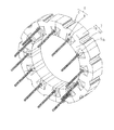
- FIG. 2 is a perspective view showing a stator in the rotating electrical machine according to Embodiment 1 of the present invention
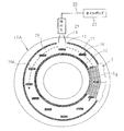
- FIG. 3 is Embodiment 1 of the present invention.
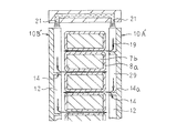
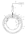
- FIG. 4 is a schematic cross-sectional view for explaining the flow of cooling oil in the stator coil of the rotary electric machine according to Embodiment 1 of the present invention. 1 to 4, the arrows indicate the flow of the cooling oil.
- the rotating electrical machine 100 surrounds the rotor 1 via a fixed gap between the rotor 1 and the rotor 1 rotatably disposed in the first and second exterior frames 10 ⁇ / b> A and 10 ⁇ / b> B.
- the stator 5 held by the first and second exterior frames 10 ⁇ / b> A and 10 ⁇ / b> B and the cooling mechanism 20 for cooling the stator 5 are provided.
- the rotor 1 includes a shaft 2, a rotor core 3 fixed to the shaft 2, and a permanent magnet 4 that is attached to the rotor core 3 and forms a magnetic pole, and is rotatably disposed inside the stator 5.
- the stator 5 includes an annular stator core 6 and a stator coil 8 attached to the stator core 6.
- the split core 7 includes an arc-shaped back yoke portion 7a and teeth 7b protruding radially inward from the circumferential central portion of the inner peripheral surface of the back yoke portion 7a.
- the stator core 6 is constituted by twelve divided cores 7 arranged in an annular shape by butting the side surfaces in the circumferential direction of the back yoke portion 7a.
- each of the stator coils 8 includes 12 coils 8a produced by winding a conductor wire around the teeth 7b of the split core 7 a plurality of times.
- coils 8a constitute, for example, a U-phase coil, a V-phase coil, a W-phase coil, a U-phase coil, a V-phase coil, a W-phase coil,... Is a three-phase AC winding.
- the first exterior frame 10A is manufactured in an arm shape that covers one side of the stator 5 in the axial direction. And as FIG. 3 shows, the outer-diameter side peripheral wall part 11 and the inner peripheral side peripheral wall part 12 each protrude in the axial direction, and are formed concentrically and annularly on the inner wall surface of the first exterior frame 10A. Thus, an annular cooling oil passage 29 is formed. The position of the upper part in the vertical direction of the outer diameter side peripheral wall portion 11 is cut off to constitute the oil inlet 13. Further, twelve oil flow direction changing protrusions 14 are formed on the same circumference on the inner wall surface of the first exterior frame 10 ⁇ / b> A so as to protrude in the axial direction and face the cooling oil receiving surface 14 a upward. Yes.
- the cooling oil receiving surface 14a is formed on a flat surface orthogonal to the vertical direction.
- the twelve oil flow direction changing projections 14 are formed in the cooling oil passage 29 so as to face each other in the axial direction between the coils 8a adjacent to each other in the circumferential direction. Further, the protruding amounts in the axial direction of the outer peripheral side peripheral wall portion 11, the inner peripheral side peripheral wall portion 12, and the oil flow direction changing projection 14 are equal.
- the second exterior frame 10 ⁇ / b> B is formed in an arm shape that covers the other axial side of the stator 5. And the cooling oil path is not formed in the inner wall surface of 10B of a 2nd exterior frame.
- the cooling mechanism 20 is located above the oil inlet 13 in the vertical direction, injects the cooling oil 19 and supplies the cooling oil 19 from the oil inlet 13 into the cooling oil passage 29, and the first and second exterior frames. And an oil pump 22 that sucks the cooling oil 19 accumulated in the lower spaces in 10 ⁇ / b> A and 10 ⁇ / b> B and pumps it to the injection hole 21.
- the cooling oil 19 is pumped to the injection hole 21 by the oil pump 22 and is injected from the injection hole 21.
- the cooling oil 19 injected from the injection holes 21 is supplied from the oil inlet 13 into the cooling oil passage 29 and flows downward in the cooling oil passage 29 as indicated by arrows in FIG.
- the cooling oil 19 that has flowed downward in the cooling oil passage 29 hits the cooling oil receiving surface 14a of the oil flow direction changing projection 14 and is converted into an axial flow.
- the cooling oil 19 converted into the axial flow is ejected from the cooling oil passage 29, that is, from one side in the axial direction between the adjacent coils 8a as shown by arrows in FIGS.
- a part of the cooling oil 19 flows between the coils 8a and flows to the other side in the axial direction, as indicated by an arrow in FIG.
- the cooling oil that has flowed to the other side in the axial direction of the coil 8a flows downward through the coil 8a. Further, the remaining portion of the cooling oil 19 hits the surface of the coil 8a and flows downward through the coil 8a.
- the annular cooling oil passage 29 formed on the inner wall surface of the first exterior frame 10A is an open passage having an opening on the side facing the stator coil 8. Therefore, the pressure loss in the cooling oil passage 29 is reduced, and the load on the oil pump 22 is reduced. Further, since the cooling oil 19 flows in the cooling oil passage 29 due to its own weight and pressure due to its own weight, the load on the oil pump 22 is reduced. As a result, the power of the oil pump 22 can be reduced, the oil pump 22 can be downsized, and the rotating electrical machine 100 can be downsized.
- the cooling oil 19 passes between the adjacent coils 8a from one side in the axial direction to the other side. Flowing into. Thereby, the contact area of the cooling oil 19 and the coil 8a becomes large, and between the coil 8a which becomes the hottest can be cooled effectively.
- the oil flow direction changing projections 14 are arranged in the cooling oil passage 29 so as to face each other between the coils 8a adjacent in the circumferential direction, the coils 8a constituting the stator coil 8 are uniformly cooled. The As a result, it is possible to avoid in advance that the temperature of some of the coils 8a becomes high and the thermal rating of the rotating electrical machine 100 cannot be improved, and downsizing of the rotating electrical machine 100 can be realized.
- the coil 8a is a concentrated winding coil, the coil end is small, and the rotating electrical machine 100 can be downsized. Further, the concentrated winding coil 8a has a small copper loss and a small amount of heat generation. Therefore, by adopting this cooling structure, the temperature rise of the coil 8a can be reliably suppressed.
- the oil flow direction changing projection is formed so that the cooling oil receiving surface made of a flat surface is in the horizontal direction, but the oil flow direction changing projection is made of a flat surface.
- the cooling oil receiving surface may be formed on an inclined surface that gradually decreases toward the coil. In this case, the cooling oil hits the cooling oil receiving surface and is supplied between the coils at an increased flow velocity, so that the coils can be cooled more efficiently.
- the oil flow direction changing projection is arranged such that the cooling oil receiving surface, which is a flat surface, faces between the coils adjacent in the circumferential direction.
- the oil flow direction changing projection should be arranged so that the cooling oil receiving surface consisting of a flat surface is not flush with the circumferentially adjacent coils but slightly above the vertical direction. It is desirable to arrange.
- FIG. FIG. 5 is a schematic cross-sectional view illustrating the flow of cooling oil in a stator coil of a rotary electric machine according to Embodiment 2 of the present invention.
- an outer diameter side peripheral wall portion (not shown) and an inner peripheral side peripheral wall portion 12 protrude in the axial direction, respectively, and are concentric with the inner wall surfaces of the first and second exterior frames 10A ′ and 10B ′.
- an annular cooling oil passage 29 is formed.
- the position of the upper part in the vertical direction of the outer diameter side peripheral wall portion is cut off to constitute an oil inlet.
- the oil flow direction changing projections 14 respectively protrude in the axial direction, with the cooling oil receiving surface 14a facing upward, on the inner wall surfaces of the first and second exterior frames 10A ′ and 10B ′, and the same circumference. Six are formed on the top.
- the oil flow direction changing projections 14 are formed on the inner peripheral wall surfaces of the exterior frames 10 ⁇ / b> A ′ and 10 ⁇ / b> B ′ so that the circumferential positions are staggered. As a result, the oil flow direction changing projections 14 are alternately arranged between the adjacent coils 8a in the circumferential direction, one side in the axial direction, and the other side.
- the second embodiment is configured in the same manner as in the first embodiment except that the first and second exterior frames 10A ′ and 10B ′ are used instead of the first and second exterior frames 10A and 10B. Has been.
- the cooling oil 19 supplied from the injection hole 21 into the cooling oil passage 29 of the first exterior frame 10A ′ flows downward in the cooling oil passage 29, and the oil flow direction changing projections 14 Each is converted into an axial flow and injected between the coils 8a from one axial side. Then, the cooling oil flows between the coils 8a from one side in the axial direction to the other side.
- the cooling oil 19 supplied from the injection hole 21 into the cooling oil passage 29 of the second exterior frame 10B ′ flows downward in the cooling oil passage 29 and flows axially at each of the oil flow direction change projections 14. And is injected between the coils 8a from the other side in the axial direction.
- the cooling oil 19 flows between the coils 8a from the other side in the axial direction to one side. Therefore, also in this second embodiment, the same effect as in the first embodiment can be obtained.
- the cooling oil 19 flows between the coils 8a from one side in the axial direction to the other side while exchanging heat with the coil 8a, the temperature of the cooling oil 19 gradually increases from one side in the axial direction toward the other side.
- the cooling oil 19 flows between the coils 8a from the other side in the axial direction to one side while exchanging heat with the coil 8a, so that the temperature of the cooling oil 19 gradually increases from the other side in the axial direction toward the one side. Become.
- the first and second outer casings are arranged so that the oil flow direction changing projections 14 are alternately opposed to each other between the adjacent coils 8a in the circumferential direction, one side in the axial direction, and the other side. It is formed on the inner peripheral wall surface of the frames 10A ′ and 10B ′. Accordingly, since the cooling oil flowing between the two adjacent coils 8a becomes a counter flow, the temperature distribution in the axial direction of the coil 8a is made uniform, and the coil 8a can be cooled effectively.
- FIG. 6 is a schematic cross-sectional view illustrating the flow of cooling oil in a stator coil of a rotating electrical machine according to Embodiment 3 of the present invention.
- an outer diameter side peripheral wall portion (not shown) and an inner peripheral side peripheral wall portion 12 project in the axial direction, and are concentrically and annularly formed on the inner wall surface of the second exterior frame 10B ′′.
- an annular cooling oil passage 29 is formed, the position of the upper portion in the vertical direction of the outer diameter side peripheral wall portion is cut off to form an oil inlet, and the oil flow direction changing projections 14 are respectively axially arranged.
- 12 are formed on the same circumference on the inner wall surface of the second exterior frame 10B ′′ with the cooling oil receiving surface 14a facing upward.
- the oil flow direction changing projections 14 are formed on the inner peripheral wall surface of the second exterior frame 10B ′′ so as to face each other between the coils 8a adjacent in the circumferential direction.
- the third embodiment is configured in the same manner as in the first embodiment except that the second exterior frame 10B "is used instead of the second exterior frame 10B.
- the cooling oil 19 supplied from the injection hole 21 into the cooling oil passage 29 of the first exterior frame 10A flows downward in the cooling oil passage 29, and each of the oil flow direction changing projections 14 is supplied. Is converted into an axial flow and injected between the coils 8a from one side in the axial direction. Then, the cooling oil 19 flows between the coils 8a from one side in the axial direction to the other side.
- the cooling oil 19 supplied from the injection hole 21 into the cooling oil passage 29 of the second exterior frame 10B ′′ flows downward in the cooling oil passage 29 and flows axially at each of the oil flow direction changing projections 14.
- the cooling oil 19 flows between the coils 8a from the other side in the axial direction to one side, and is axially central in the axial direction between the coils 8a. It merges with the cooling oil that has flowed from one side to the other.
- the temperature distribution in the axial direction of the coil 8a is made uniform, and the coil 8a can be cooled effectively.
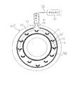
- FIG. 7 is a front view showing a first exterior frame in a rotary electric machine according to Embodiment 4 of the present invention.
- each of the oil flow direction changing projections 14 ′ protrudes in the axial direction with a cross-sectional shape orthogonal to the axial direction projecting vertically downward, and the inner wall surface of the first exterior frame 10A ′′
- twelve are formed on the same circumference, that is, the cooling oil receiving surface 14a ′ is formed as a convex concave surface downstream in the flow direction of the cooling oil 19.
- the fourth embodiment is configured in the same manner as in the first embodiment except that the first exterior frame 10A ′′ is used instead of the first exterior frame 10A.
- the cooling oil receiving surface 14a 'of the oil flow direction changing projection 14' is a concave surface convex downward. Therefore, the amount of the cooling oil 19 flowing through the cooling oil passage 29 by the oil flow direction changing projection 14 ′ increases, so that a large amount of the cooling oil 19 can be supplied between the coils 8a, and the coil 8a can be effectively used. Can be cooled to.
- FIG. 8 is a cross-sectional view of a coil end cover in a rotary electric machine according to Embodiment 5 of the present invention as viewed from the inside in the axial direction.
- FIG. 8 is a cross-sectional view of a cross section of the coil end cover taken along a plane orthogonal to the axial direction, as viewed from one side in the axial direction, and arrows in FIG. 8 indicate the flow of cooling oil.
- the coil end cover 30 is fixed to the axially inner surface of the first exterior frame with, for example, screws, and covers the protruding portion (coil end) of the coil 8 a that protrudes to one axial end side of the stator core 6. It is arranged as follows.
- the coil end cover 30 is formed in a circular shape with a U-shaped cross section in which one end in the axial direction of the outer diameter side peripheral wall portion 31 and the inner diameter side peripheral wall portion 32 is connected by a bottom portion (not shown). Configure.
- a cooling oil receiving port 33 is provided at an upper portion in the vertical direction of the outer diameter side peripheral wall portion 31, and the cooling oil 19 is supplied into the cooling oil passage 39.
- the 1st exterior cover is produced in the arm shape which covers the axial direction one side of the stator 5, and the outer-diameter side and inner-diameter side surrounding wall part which comprises a cooling oil path is not formed.
- the first oil flow direction changing projection 35 has an upper surface (cooling oil receiving surface) as a flat surface perpendicular to the vertical direction, and protrudes in the axial direction from the inner peripheral side peripheral wall portion 32 side of the upper portion of the coil end cover 30 in the vertical direction. It is formed to do.
- the second oil flow direction changing projection 36 has a cross-sectional shape orthogonal to the axial direction as an arc shape centered on the axis of the coil end cover 30, on the radially outer side of the first oil flow direction changing projection 35, and It is formed so as to protrude in the axial direction from the bottom portion while being spaced apart in the circumferential direction.
- the third oil flow direction changing projection 37 is formed to protrude radially outward from the downstream end of the second oil flow direction changing projection 36 in the flow direction of the cooling oil 19. Further, a plurality of fourth oil flow direction changing projections 38 protrude from the inner diameter side peripheral wall portion 32 outward in the radial direction, and are formed in the circumferential direction.
- the upstream surface of the third and fourth oil flow direction changing projections 37 and 38 in the flow direction of the cooling oil 19 is the cooling oil receiving surface.
- the first oil flow direction changing projection 35 converts the cooling oil 19 flowing from the cooling oil receiving port 33 into an axial flow and a circumferential flow.
- the second oil flow direction changing projection 36 converts the cooling oil 19 flowing from the cooling oil receiving port 33 into a circumferential flow.
- the third and fourth oil flow direction changing projections 37 and 38 convert the cooling oil 19 flowing in the circumferential direction in the cooling oil passage 39 into an axial flow.
- the first, third, and fourth oil flow direction changing projections 35, 37, 38 are arranged on one side in the axial direction between the coils 8a adjacent in the circumferential direction.
- the cooling oil 19 injected from the injection hole 21 is supplied from the cooling oil receiving port 33 into the cooling oil passage 39 of the coil end cover 30.
- the cooling oil 19 supplied into the cooling oil passage 39 first hits the cooling oil receiving surface of the first oil flow direction changing projection 35, part of which is converted into an axial flow and supplied between the coils 8a. The remainder flows in the circumferential direction.
- the cooling oil 19 supplied into the cooling oil passage 39 is caused to flow in the circumferential direction by the second oil flow direction changing projection 36. Then, the cooling oil 19 that flows in the circumferential direction in the cooling oil passage 39 strikes the cooling oil receiving surfaces of the third and fourth oil flow direction changing projections 37 and 38 and is converted into an axial flow, between the corresponding coils 8a. To be supplied.
- the first, third, and fourth oil flow direction changing projections 35, 37, 38 are disposed only in the upper half region of the cooling oil passage 39, but in an annular shape. It has been confirmed that not only the upper half area of the group of coils arranged but also the lower half area of the group of coils can be effectively cooled. That is, a part of the cooling oil 19 supplied to the coil by the first, third and fourth oil flow direction changing projections 35, 37, 38 descends along the surface of the coil, and the lower half of the coil group While being supplied also to the area, the cooling oil 19 is accumulated in the lower spaces in the first and second exterior frames, so that the lower half area of the group of coils is effectively cooled.
- FIG. 9 is a perspective view showing a stator in a rotary electric machine according to Embodiment 6 of the present invention
- FIG. 10 is a perspective view showing coils constituting a stator coil in the rotary electric machine according to Embodiment 6 of the present invention
- FIG. FIG. 12 is a front view showing a coil constituting a stator coil in a rotary electric machine according to Embodiment 6 of the present invention
- FIG. 12 is an end view showing the coil constituting the stator coil in the rotary electric machine according to Embodiment 6 of the invention. .
- the stator 40 includes an annular stator core 41 and a stator coil 43 attached to the stator core 41.
- the stator core 41 includes a split core 42 that includes an arcuate back yoke portion 42a and teeth 42b that protrude radially inward from the circumferential center of the inner circumferential surface of the back yoke portion 42a.
- the stator core 41 is configured by arranging the split cores 42 in an annular shape by abutting the circumferential side surfaces of the back yoke portion 42a.
- the stator coil 43 is configured by arranging the coils 50 on the stator core 41 in the circumferential direction at a one-slot pitch.
- the coil 50 is, for example, a distributed winding produced by winding a conductor wire 51 made of a continuous rectangular copper wire, which is insulated with an enamel resin and has no connection portion, in an edgewise manner.
- the coil 50 includes a first straight portion 50a, a first coil end portion 50e, a second straight portion 50b, a second coil end portion 50f, and a third straight portion.
- Two ⁇ -shaped coil patterns composed of 50c, the third coil end portion 50g, and the fourth straight portion 50d are arranged in the length direction of the short side of the rectangular cross section of the conductor wire 51, and the fourth straight portion 50d and the first straight line are arranged.
- the part 50 a is connected by a connecting line 52.
- the connecting wire 52 comprises a coil end part, and the winding start end part and winding end part of the conductor wire 51 become a coil terminal.
- a first coil end portion 50e having a first coil end portion 50e arranged in the circumferential direction at a one-slot pitch is disposed on one end side in the axial direction of a stator coil 53 configured by arranging the coils 50 in the circumferential direction at a one-slot pitch.
- the third coil end portion 50g in which the third coil end portions 50g are arranged in the circumferential direction at a slot pitch are alternately arranged in four layers in the radial direction.
- the sixth embodiment has the same configuration as that of the first embodiment except that the stator 40 is used instead of the stator 5.
- the cooling oil 19 injected from the injection hole 21 is supplied from the oil inlet 13 into the cooling oil passage 29 and the oil flow direction changing projection 14 is connected. It hits the customer oil receiving surface 14a and is converted into an axial flow. As shown by the arrow in FIG. 9, the cooling oil 19 converted into the axial flow flows between the first coil end portion 50e and the third coil end portion 50g of the coil 50 adjacent in the circumferential direction from one axial direction side. Supplied in between and flows from one axial side of the coil 50 to the other. Therefore, in the sixth embodiment, the same effect as in the first embodiment can be obtained.
- the torque characteristics can be improved as compared with the concentrated winding coil 8a in the first embodiment, but the coil end is enlarged and the copper loss is reduced. It becomes large and the calorific value becomes large.
- the cooling oil 19 can flow between the coils 50 and the temperature rise of the coils 50 can be suppressed, so that a rotating electrical machine having excellent torque characteristics can be realized.
- a distributed winding coil produced by winding a conductor wire in a ⁇ -shaped coil pattern is used.
- the distributed winding coil is not limited to this, and for example, the conductor wire is spiral. It may be a turtle shell-shaped coil wound around.
- the oil flow direction changing projection is formed in a flat plate shape or a plate shape having a circular arc shape, but the oil flow direction changing projection is not limited to these shapes, What is necessary is just to be able to change the flow direction of oil into an axial direction, and for example, it may be produced in a plate shape having a V-shaped cross section or a corrugated cross section.
- the protrusion for oil flow direction conversion is arrange
- the oil flow direction protrusion is not necessarily arrange
Landscapes
- Engineering & Computer Science (AREA)
- Power Engineering (AREA)
- Motor Or Generator Cooling System (AREA)
- Motor Or Generator Frames (AREA)
Abstract
Description
油流れ方向変換用突起が周方向に配列されているので、冷却油が、環状に配列された複数のコイルに略均一に供給される。これにより、コイル温度が均一化され、回転電機の熱定格が向上されるので、回転電機の小型化が図られる。さらに、冷却油が、最も熱くなるコイル間に集中的に供給されるので、コイルを効果的に冷却することができる。
図1はこの発明の実施の形態1に係る回転電機を示す斜視図、図2はこの発明の実施の形態1に係る回転電機におけるステータを示す斜視図、図3はこの発明の実施の形態1に係る回転電機における第1外装フレームを示す正面図、図4はこの発明の実施の形態1に係る回転電機のステータコイルにおける冷却油の流れを説明する模式断面図である。なお、図1から図4中、矢印は冷却油の流れを示している。
また、上記実施の形態1では、油流れ方向変換用突起は、その平坦面からなる冷却油受け面が、周方向に隣り合うコイル間に相対するように配設されているが、重力の影響を考慮すれば、平坦面からなる冷却油受け面が、周方向に隣り合うコイル間に対して、面一ではなく、わずかに鉛直方向の上方に位置するように、油流れ方向変換用突起を配設することが望ましい。
図5はこの発明の実施の形態2に係る回転電機のステータコイルにおける冷却油の流れを説明する模式断面図である。
したがって、この実施の形態2においても、実施の形態1と同様の効果が得られる。
図6はこの発明の実施の形態3に係る回転電機のステータコイルにおける冷却油の流れを説明する模式断面図である。
図7はこの発明の実施の形態4に係る回転電機における第1外装フレームを示す正面図である。
なお、実施の形態4は、第1外装フレーム10Aに替えて第1外装フレーム10A"を用いている点を除いて、実施の形態1と同様に構成されている。
図8はこの発明の実施の形態5に係る回転電機におけるコイルエンドカバーを軸方向内側から見た断面図である。なお、図8は、コイルエンドカバーを軸方向と直交する平面で切った断面を軸方向一側から見た断面図であり、図8中、矢印は冷却油の流れを示している。
図9はこの発明の実施の形態6に係る回転電機におけるステータを示す斜視図、図10はこの発明の実施の形態6に係る回転電機におけるステータコイルを構成するコイルを示す斜視図、図11はこの発明の実施の形態6に係る回転電機におけるステータコイルを構成するコイルを示す正面図、図12はこの発明の実施の形態6に係る回転電機におけるステータコイルを構成するコイルを示す端面図である。
なお、実施の形態6は、ステータ5に替えてステータ40を用いている点を除いて、実施の形態1と同様に構成されている。
したがって、この実施の形態6においても、実施の形態1と同様に効果が得られる。
また、上記各実施の形態では、油流れ方向変換用突起がコイル間の全てに相対するように配置されているが、油流れ方向突起は必ずしもコイル間の全てに相対するように配置されている必要はなく、周方向に略均一に分布していればよく、例えば周方向に1つ置きのコイル間に相対するように配置されていてもよい。
Claims (10)
- 外装フレームと、
シャフトの軸方向を水平として上記外装フレーム内に回転可能に配設されたロータと、
上記ロータを囲繞するように同軸に配置されて上記外装フレームに保持された環状のステータコア、および上記ステータコアに装着されて環状に配列された複数のコイルを有するステータと、
環状に配列された上記複数のコイルと軸方向に相対して上記外装フレーム内に構成され、上記複数のコイルと相対する面を開口とする環状の冷却油路と、
オイルポンプと、
上記オイルポンプから圧送された冷却油を上方から上記冷却油路内に噴射する噴射孔と、
それぞれ、上記複数のコイルのコイル間に相対して、かつ冷却油受け面を上記冷却油の流れ方向の上流側に向けて上記冷却油路内に設けられて、周方向に配列され、上記冷却油路を流れる上記冷却油を軸方向の流れに変換して上記コイル間に供給する複数の油流れ方向変換用突起と、
を有する回転電機。 - 上記複数の油流れ方向変換用突起のそれぞれの上記冷却油受け面が上記冷却油の流れ方向の下流側に凸の凹面に形成されている請求項1記載の回転電機。
- 上記冷却油路が、上記ステータの軸方向一側にのみ配設されている請求項1又は請求項2記載の回転電機。
- 上記冷却油路が、上記ステータの軸方向両側に配設されている請求項1又は請求項2記載の回転電機。
- 上記複数の油流れ方向変換用突起は、上記ステータの軸方向両側に配設されている上記冷却油路のそれぞれに、周方向の位置を一致させて設けられ、上記冷却油を軸方向両側から同じ上記コイル間に供給する請求項4記載の回転電機。
- 上記複数の油流れ方向変換用突起は、上記ステータの軸方向両側に配設されている上記冷却油路のそれぞれに、周方向の位置が互い違いとなるように設けられ、上記冷却油を軸方向から上記コイル間に交互に供給する請求項4記載の回転電機。
- 上記冷却油路は、上記外装フレームの内壁面に形成されている請求項1から請求項6のいずれか1項に記載の回転電機。
- 上記外装フレームに装着されて、環状に配列された上記複数のコイルを覆うように配設される環状のコイルエンドカバーをさらに備え、
上記コイルエンドカバーが上記冷却油路を構成する請求項1から請求項6のいずれか1項に記載の回転電機。 - 上記複数のコイルが、集中巻コイルである請求項1から請求項8のいずれか1項に記載の回転電機。
- 上記複数のコイルが、分布巻コイルである請求項1から請求項8のいずれか1項に記載の回転電機。
Priority Applications (5)
| Application Number | Priority Date | Filing Date | Title |
|---|---|---|---|
| CN201480078943.4A CN106464086B (zh) | 2014-05-27 | 2014-05-27 | 旋转电机 |
| PCT/JP2014/063975 WO2015181889A1 (ja) | 2014-05-27 | 2014-05-27 | 回転電機 |
| EP14893469.8A EP3136557B1 (en) | 2014-05-27 | 2014-05-27 | Rotating electric machine |
| US15/304,592 US10404139B2 (en) | 2014-05-27 | 2014-05-27 | Rotary electric machine |
| JP2016523009A JP6526647B2 (ja) | 2014-05-27 | 2014-05-27 | 回転電機 |
Applications Claiming Priority (1)
| Application Number | Priority Date | Filing Date | Title |
|---|---|---|---|
| PCT/JP2014/063975 WO2015181889A1 (ja) | 2014-05-27 | 2014-05-27 | 回転電機 |
Publications (1)
| Publication Number | Publication Date |
|---|---|
| WO2015181889A1 true WO2015181889A1 (ja) | 2015-12-03 |
Family
ID=54698273
Family Applications (1)
| Application Number | Title | Priority Date | Filing Date |
|---|---|---|---|
| PCT/JP2014/063975 Ceased WO2015181889A1 (ja) | 2014-05-27 | 2014-05-27 | 回転電機 |
Country Status (5)
| Country | Link |
|---|---|
| US (1) | US10404139B2 (ja) |
| EP (1) | EP3136557B1 (ja) |
| JP (1) | JP6526647B2 (ja) |
| CN (1) | CN106464086B (ja) |
| WO (1) | WO2015181889A1 (ja) |
Cited By (4)
| Publication number | Priority date | Publication date | Assignee | Title |
|---|---|---|---|---|
| WO2019039243A1 (ja) * | 2017-08-25 | 2019-02-28 | 株式会社 明電舎 | 回転電機の固定子の冷却構造 |
| JP2019088116A (ja) * | 2017-11-08 | 2019-06-06 | タイガースポリマー株式会社 | 回転電機の冷却構造 |
| CN111193351A (zh) * | 2020-03-16 | 2020-05-22 | 清华大学 | 电机机壳 |
| JP2024016430A (ja) * | 2022-07-26 | 2024-02-07 | トヨタ自動車株式会社 | 回転電機の冷却構造 |
Families Citing this family (12)
| Publication number | Priority date | Publication date | Assignee | Title |
|---|---|---|---|---|
| KR102452689B1 (ko) | 2017-09-26 | 2022-10-11 | 현대자동차주식회사 | 오일 코일순환방식 모터 및 친환경차량 |
| WO2019187021A1 (ja) * | 2018-03-30 | 2019-10-03 | 本田技研工業株式会社 | 回転電機の冷却構造 |
| EP3886299B1 (en) * | 2018-11-20 | 2024-06-26 | JATCO Ltd | Motor oil cooling structure |
| EP3913777B1 (en) | 2019-01-14 | 2025-04-02 | Shanghai Pangood Power Technology Co., Ltd. | Axial magnetic field motor with liquid cooled stator |
| EP3709484A1 (de) * | 2019-03-14 | 2020-09-16 | Siemens Aktiengesellschaft | Gekapselte elektrische maschine mit äusserem flüssigkeitskühlkreislauf |
| JP6958655B2 (ja) * | 2020-03-19 | 2021-11-02 | 株式会社明電舎 | 回転機 |
| CN112615445B (zh) * | 2020-11-25 | 2022-05-13 | 华为数字能源技术有限公司 | 电机、动力总成和设备 |
| JP7626230B2 (ja) * | 2021-07-26 | 2025-02-04 | 株式会社アイシン | 駆動装置 |
| CN115189520B (zh) * | 2022-07-25 | 2024-06-25 | 重庆长安汽车股份有限公司 | 一种电驱油冷电机及汽车 |
| JP7468591B1 (ja) | 2022-09-29 | 2024-04-16 | 株式会社明電舎 | 回転電機の冷却構造および回転電機 |
| CN118282080B (zh) * | 2024-06-03 | 2024-09-27 | 苏州英磁新能源科技有限公司 | 一种轴向磁通盘式电机冷却系统及油道结构 |
| CN118554700B (zh) * | 2024-06-04 | 2025-10-28 | 广东汇天航空航天科技有限公司 | 冷却结构、电机和交通设备 |
Citations (5)
| Publication number | Priority date | Publication date | Assignee | Title |
|---|---|---|---|---|
| JP2001145302A (ja) * | 1999-11-17 | 2001-05-25 | Nissan Motor Co Ltd | モータの冷却装置 |
| JP2003009454A (ja) * | 2001-06-20 | 2003-01-10 | Nissan Motor Co Ltd | 回転電機 |
| JP2004238952A (ja) * | 2003-02-06 | 2004-08-26 | Yasuo Suina | 入り隅用役物雨樋 |
| JP2012170299A (ja) * | 2011-02-16 | 2012-09-06 | Toyota Motor Corp | モータの冷却装置 |
| JP2014042414A (ja) * | 2012-08-23 | 2014-03-06 | Toyota Motor Corp | 回転電機装置 |
Family Cites Families (12)
| Publication number | Priority date | Publication date | Assignee | Title |
|---|---|---|---|---|
| JP3385373B2 (ja) | 1994-10-31 | 2003-03-10 | アイシン・エィ・ダブリュ株式会社 | モ−タの冷却回路 |
| FR2736769B1 (fr) * | 1995-07-13 | 1997-10-10 | Jeumont Ind | Procede de reparation d'une boite a fluide de refroidissement d'une barre statorique d'un alternateur electrique |
| US5798587A (en) * | 1997-01-22 | 1998-08-25 | Industrial Technology Research Institute | Cooling loop structure of high speed spindle |
| JP3707250B2 (ja) * | 1997-08-06 | 2005-10-19 | 富士電機システムズ株式会社 | 回転電気機械の円筒形回転子 |
| JP4167886B2 (ja) * | 2002-11-25 | 2008-10-22 | 株式会社日本自動車部品総合研究所 | 回転電機 |
| JP2006033924A (ja) | 2004-07-13 | 2006-02-02 | Toshiba Corp | 車両用通風冷却形主電動機 |
| JP5347380B2 (ja) | 2008-08-28 | 2013-11-20 | アイシン精機株式会社 | モータの油冷構造 |
| US8487489B2 (en) * | 2010-07-30 | 2013-07-16 | General Electric Company | Apparatus for cooling an electric machine |
| JP2013207930A (ja) | 2012-03-28 | 2013-10-07 | Honda Motor Co Ltd | 回転電機のステータ構造 |
| US20160141921A1 (en) * | 2014-11-17 | 2016-05-19 | Arnold Magnetic Technologies | Helical heat exchanger for electric motors |
| US20160164378A1 (en) * | 2014-12-04 | 2016-06-09 | Atieva, Inc. | Motor Cooling System |
| JP6560033B2 (ja) * | 2015-06-25 | 2019-08-14 | 株式会社日立製作所 | 回転電機、並びに回転電機の冷却システム |
-
2014
- 2014-05-27 US US15/304,592 patent/US10404139B2/en active Active
- 2014-05-27 JP JP2016523009A patent/JP6526647B2/ja active Active
- 2014-05-27 EP EP14893469.8A patent/EP3136557B1/en active Active
- 2014-05-27 WO PCT/JP2014/063975 patent/WO2015181889A1/ja not_active Ceased
- 2014-05-27 CN CN201480078943.4A patent/CN106464086B/zh active Active
Patent Citations (5)
| Publication number | Priority date | Publication date | Assignee | Title |
|---|---|---|---|---|
| JP2001145302A (ja) * | 1999-11-17 | 2001-05-25 | Nissan Motor Co Ltd | モータの冷却装置 |
| JP2003009454A (ja) * | 2001-06-20 | 2003-01-10 | Nissan Motor Co Ltd | 回転電機 |
| JP2004238952A (ja) * | 2003-02-06 | 2004-08-26 | Yasuo Suina | 入り隅用役物雨樋 |
| JP2012170299A (ja) * | 2011-02-16 | 2012-09-06 | Toyota Motor Corp | モータの冷却装置 |
| JP2014042414A (ja) * | 2012-08-23 | 2014-03-06 | Toyota Motor Corp | 回転電機装置 |
Non-Patent Citations (1)
| Title |
|---|
| See also references of EP3136557A4 * |
Cited By (9)
| Publication number | Priority date | Publication date | Assignee | Title |
|---|---|---|---|---|
| WO2019039243A1 (ja) * | 2017-08-25 | 2019-02-28 | 株式会社 明電舎 | 回転電機の固定子の冷却構造 |
| JP2019041487A (ja) * | 2017-08-25 | 2019-03-14 | 株式会社明電舎 | 回転電機の固定子の冷却構造 |
| CN111052565A (zh) * | 2017-08-25 | 2020-04-21 | 株式会社明电舍 | 旋转电机的定子的冷却结构 |
| US11070099B2 (en) | 2017-08-25 | 2021-07-20 | Meidensha Corporation | Cooling structure of stator of rotating electrical machine |
| JP2019088116A (ja) * | 2017-11-08 | 2019-06-06 | タイガースポリマー株式会社 | 回転電機の冷却構造 |
| CN111193351A (zh) * | 2020-03-16 | 2020-05-22 | 清华大学 | 电机机壳 |
| JP2024016430A (ja) * | 2022-07-26 | 2024-02-07 | トヨタ自動車株式会社 | 回転電機の冷却構造 |
| US12413117B2 (en) | 2022-07-26 | 2025-09-09 | Toyota Jidosha Kabushiki Kaisha | Cooling structure for rotary electric machine |
| JP7790292B2 (ja) | 2022-07-26 | 2025-12-23 | トヨタ自動車株式会社 | 回転電機の冷却構造 |
Also Published As
| Publication number | Publication date |
|---|---|
| EP3136557A4 (en) | 2017-12-13 |
| CN106464086A (zh) | 2017-02-22 |
| EP3136557B1 (en) | 2019-09-18 |
| CN106464086B (zh) | 2019-11-15 |
| US20170047822A1 (en) | 2017-02-16 |
| US10404139B2 (en) | 2019-09-03 |
| JP6526647B2 (ja) | 2019-06-05 |
| EP3136557A1 (en) | 2017-03-01 |
| JPWO2015181889A1 (ja) | 2017-04-20 |
Similar Documents
| Publication | Publication Date | Title |
|---|---|---|
| JP6526647B2 (ja) | 回転電機 | |
| JP5642291B2 (ja) | 回転電機 | |
| JP6072866B1 (ja) | 回転電機 | |
| CN103688445B (zh) | 电动机的定子和永磁式旋转电机 | |
| JP6079012B2 (ja) | 3相回転電機 | |
| JP5386263B2 (ja) | 回転電機 | |
| US10153673B2 (en) | Production method for rotating electrical machine | |
| JP5771958B2 (ja) | ポンプ装置 | |
| CN108900014A (zh) | 一种定子铁芯、定子和电机 | |
| JP2018152957A (ja) | 回転電機 | |
| JP2016149905A (ja) | 回転電機のステータおよびその製造方法 | |
| JP2013153643A (ja) | 単相誘導モータ | |
| US10193420B2 (en) | Rotating electric machine | |
| KR20230024411A (ko) | 모터 | |
| JP5955437B1 (ja) | 回転電機 | |
| EP3039776B1 (en) | Electrical machine with stator housing having improved cooling efficiency | |
| JP2013219906A (ja) | 単相誘導モータ | |
| JP5330860B2 (ja) | 回転電機 | |
| JP2019154197A (ja) | 回転電機 | |
| JP2014100038A (ja) | 回転電機の固定子 | |
| WO2021199376A1 (ja) | 固定子および回転電機 | |
| JP2009100522A (ja) | 回転電機 | |
| JP2013215028A (ja) | 単相誘導モータ | |
| JP2010166647A (ja) | クローポール型モータ | |
| JP5363221B2 (ja) | ステータ |
Legal Events
| Date | Code | Title | Description |
|---|---|---|---|
| 121 | Ep: the epo has been informed by wipo that ep was designated in this application |
Ref document number: 14893469 Country of ref document: EP Kind code of ref document: A1 |
|
| ENP | Entry into the national phase |
Ref document number: 2016523009 Country of ref document: JP Kind code of ref document: A |
|
| WWE | Wipo information: entry into national phase |
Ref document number: 15304592 Country of ref document: US |
|
| REEP | Request for entry into the european phase |
Ref document number: 2014893469 Country of ref document: EP |
|
| WWE | Wipo information: entry into national phase |
Ref document number: 2014893469 Country of ref document: EP |
|
| NENP | Non-entry into the national phase |
Ref country code: DE |