WO2015182049A1 - 電子機器の防水接続器具及び電子機器 - Google Patents
電子機器の防水接続器具及び電子機器 Download PDFInfo
- Publication number
- WO2015182049A1 WO2015182049A1 PCT/JP2015/002380 JP2015002380W WO2015182049A1 WO 2015182049 A1 WO2015182049 A1 WO 2015182049A1 JP 2015002380 W JP2015002380 W JP 2015002380W WO 2015182049 A1 WO2015182049 A1 WO 2015182049A1
- Authority
- WO
- WIPO (PCT)
- Prior art keywords
- support portion
- exterior body
- waterproof
- ring
- shell
- Prior art date
- Legal status (The legal status is an assumption and is not a legal conclusion. Google has not performed a legal analysis and makes no representation as to the accuracy of the status listed.)
- Ceased
Links
Images




Classifications
-
- H—ELECTRICITY
- H01—ELECTRIC ELEMENTS
- H01R—ELECTRICALLY-CONDUCTIVE CONNECTIONS; STRUCTURAL ASSOCIATIONS OF A PLURALITY OF MUTUALLY-INSULATED ELECTRICAL CONNECTING ELEMENTS; COUPLING DEVICES; CURRENT COLLECTORS
- H01R13/00—Details of coupling devices of the kinds covered by groups H01R12/70 or H01R24/00 - H01R33/00
- H01R13/46—Bases; Cases
- H01R13/52—Dustproof, splashproof, drip-proof, waterproof, or flameproof cases
-
- H—ELECTRICITY
- H01—ELECTRIC ELEMENTS
- H01R—ELECTRICALLY-CONDUCTIVE CONNECTIONS; STRUCTURAL ASSOCIATIONS OF A PLURALITY OF MUTUALLY-INSULATED ELECTRICAL CONNECTING ELEMENTS; COUPLING DEVICES; CURRENT COLLECTORS
- H01R13/00—Details of coupling devices of the kinds covered by groups H01R12/70 or H01R24/00 - H01R33/00
- H01R13/46—Bases; Cases
- H01R13/52—Dustproof, splashproof, drip-proof, waterproof, or flameproof cases
- H01R13/5202—Sealing means between parts of housing or between housing part and a wall, e.g. sealing rings
-
- H—ELECTRICITY
- H01—ELECTRIC ELEMENTS
- H01R—ELECTRICALLY-CONDUCTIVE CONNECTIONS; STRUCTURAL ASSOCIATIONS OF A PLURALITY OF MUTUALLY-INSULATED ELECTRICAL CONNECTING ELEMENTS; COUPLING DEVICES; CURRENT COLLECTORS
- H01R13/00—Details of coupling devices of the kinds covered by groups H01R12/70 or H01R24/00 - H01R33/00
- H01R13/46—Bases; Cases
- H01R13/52—Dustproof, splashproof, drip-proof, waterproof, or flameproof cases
- H01R13/5216—Dustproof, splashproof, drip-proof, waterproof, or flameproof cases characterised by the sealing material, e.g. gels or resins
-
- H—ELECTRICITY
- H01—ELECTRIC ELEMENTS
- H01R—ELECTRICALLY-CONDUCTIVE CONNECTIONS; STRUCTURAL ASSOCIATIONS OF A PLURALITY OF MUTUALLY-INSULATED ELECTRICAL CONNECTING ELEMENTS; COUPLING DEVICES; CURRENT COLLECTORS
- H01R13/00—Details of coupling devices of the kinds covered by groups H01R12/70 or H01R24/00 - H01R33/00
- H01R13/46—Bases; Cases
- H01R13/52—Dustproof, splashproof, drip-proof, waterproof, or flameproof cases
- H01R13/5219—Sealing means between coupling parts, e.g. interfacial seal
-
- H—ELECTRICITY
- H01—ELECTRIC ELEMENTS
- H01R—ELECTRICALLY-CONDUCTIVE CONNECTIONS; STRUCTURAL ASSOCIATIONS OF A PLURALITY OF MUTUALLY-INSULATED ELECTRICAL CONNECTING ELEMENTS; COUPLING DEVICES; CURRENT COLLECTORS
- H01R24/00—Two-part coupling devices, or either of their cooperating parts, characterised by their overall structure
- H01R24/60—Contacts spaced along planar side wall transverse to longitudinal axis of engagement
- H01R24/62—Sliding engagements with one side only, e.g. modular jack coupling devices
-
- H—ELECTRICITY
- H01—ELECTRIC ELEMENTS
- H01R—ELECTRICALLY-CONDUCTIVE CONNECTIONS; STRUCTURAL ASSOCIATIONS OF A PLURALITY OF MUTUALLY-INSULATED ELECTRICAL CONNECTING ELEMENTS; COUPLING DEVICES; CURRENT COLLECTORS
- H01R24/00—Two-part coupling devices, or either of their cooperating parts, characterised by their overall structure
- H01R24/66—Two-part coupling devices, or either of their cooperating parts, characterised by their overall structure with pins, blades or analogous contacts and secured to apparatus or structure, e.g. to a wall
-
- H—ELECTRICITY
- H01—ELECTRIC ELEMENTS
- H01R—ELECTRICALLY-CONDUCTIVE CONNECTIONS; STRUCTURAL ASSOCIATIONS OF A PLURALITY OF MUTUALLY-INSULATED ELECTRICAL CONNECTING ELEMENTS; COUPLING DEVICES; CURRENT COLLECTORS
- H01R2107/00—Four or more poles
Definitions
- the present invention relates to a connection device used for electrical connection of various electronic devices such as a multi-function mobile phone, a multi-function portable information terminal, a portable music player, an electronic book reader, and an audio device, and more particularly, an electronic device having a waterproof function.
- the present invention relates to a waterproof connecting device for an apparatus and an electronic device including the waterproof connecting device.
- a support portion is provided in a wall shape so as to close the inside of the case at a position near the back side of the substantially cylindrical case made of resin, and the support portion is A contact terminal is introduced into the case so as to penetrate, and a space formed by the peripheral wall and the support portion at the back of the case is filled with a filler, and is embedded in the casing of the electronic device.
- a waterproof connector see Patent Document 1. This waterproof connector can prevent the water that has entered the case from entering between the case and the support part from entering between the case and the circuit board installed on the back side by the filler at the back of the case.
- a connecting device such as a connector built in an electronic device is squeezed by a plug or the like to be inserted strongly or a force to be squeezed many times, thereby partially or entirely inflating the case.
- Force is applied intermittently.
- the filler is peeled off from the inner surface of the case by this intermittent force. There may be a gap between the filler and the filler. When such a gap occurs, it becomes difficult to prevent water from entering the back side, and the waterproofness is impaired.
- This invention proposes in view of the said subject, and while being able to prevent reliably that water permeates into the back
- the waterproof connector for an electronic device includes a substantially cylindrical exterior body, a support portion that is installed in a wall shape behind the exterior body, and is supported by the support portion and introduced into the exterior body.
- a circumferential seal that is provided between the exterior body and the support portion at a position where the contact terminal, the exterior body, and the support portion are close to each other, and seals between the exterior body and the support portion.
- a stop portion a stop portion. According to this, the space between the exterior body and the support portion can be sealed with the circumferential sealing portion, and the waterproofness between the exterior body and the support portion can be ensured.
- the filler it is not necessary to fix the filler to the inner surface of the exterior body in the space on the inner side of the exterior body, and the filler is peeled off from the inner surface of the exterior body by the force applied intermittently, and the waterproof property is impaired. It will not be done.
- the circumferential sealing part is arrange
- the space for filling the filler on the back side of the exterior body is not required, the length of the waterproof connecting device can be shortened and downsized. Therefore, the area occupied by the waterproof connector can be reduced, the usable portion inside the electronic device can be increased, a more free layout design inside the electronic device can be realized, and the electronic device can be downsized.
- the sealing portion is formed of an elastic material and provided on the support portion, and the sealing portion is press-contacted circumferentially to the inner surface of the exterior body.
- the support portion is press-fitted into the exterior body. According to this, even when a force for inflating a part or the whole of the exterior body is applied and the exterior body is temporarily or permanently deformed, the elastic material sealed against the inner surface of the exterior body is sealed.
- the stop portion can follow the inner surface of the exterior body to maintain waterproofness.
- the support part can be installed at a predetermined position in the exterior body with high stability by press-fitting the support part that presses the sealing part into the exterior body.
- the waterproof connector for an electronic device is characterized in that the sealing portion is provided by press-fitting a protruding portion outward from a part of the outer peripheral surface of the support portion. According to this, it becomes possible to install the support part and the sealing part in the exterior body so as to press-fit the sealing part protruding to the outer periphery into the exterior body. In the structure installed in this way, even if an error occurs in the position of the sealing part and the support part in the exterior body, sealing between the exterior body and the support part can be performed to ensure waterproofness. It is possible to provide a margin for the positional accuracy of the stopper and the support. Therefore, the assembly accuracy can be relaxed and the manufacturing cost can be reduced, and defective products can be reduced and the yield can be improved.
- the sealing portion is provided on the entire outer peripheral surface of the support portion, the frictional resistance becomes very large when press-fitting into the exterior body, whereas the sealing portion is formed on a part of the outer peripheral surface of the support portion.
- the frictional resistance at the time of press-fitting into the exterior body can be reduced, and the assembling work can be facilitated.
- the sealing portion is an O-ring, and the O-ring is fitted in a place where the support portion can be placed. According to this, waterproof sealing between the exterior body and the support part can be performed on the exterior body and the support part of various shapes and sizes at low cost, and versatility can be improved.
- the waterproof connector for an electronic device is characterized in that the sealing portion is formed of an elastic resin integrated with the support portion. According to this, water does not enter at all from between the sealing portion and the support portion, and the waterproofness by sealing between the exterior body and the support portion can be further enhanced.
- the exterior body is made of metal. According to this, when the exterior body is made of metal, the structure in which the resin filler is provided in the space formed by the peripheral wall and the support portion at the back of the exterior body, compared with the case where the exterior body is resin.
- the resin filler and the exterior body are easy to peel off, and the possibility of impairing the waterproofing is increased, while the sealing part is pressed against the inner surface of the metallic exterior body in a circumferential shape, Durability can be increased.
- the sealing portion is provided on the front side of the support portion, and is adhered to the step portion of the exterior body in a circumferential shape.
- the front surface side of the support portion includes an appropriate surface positioned facing forward such as a front surface of the support portion or an inclined surface formed at a corner portion of the support portion disposed on the front surface side.
- the sealing portion is a waterproof double-sided tape in which one surface is bonded to the front surface side of the support portion and the other surface is bonded to the step portion of the exterior body.
- the electronic device of the present invention is characterized in that the waterproof connector for the electronic device of the present invention is housed in a housing. According to this, the electronic device which has the effect of the waterproof connector of the electronic device of the present invention can be obtained.
- the space between the exterior body and the support portion of the waterproof connector is sealed with a circumferential sealing portion, and water enters the back side from between the exterior body and the interior support portion. Can be reliably prevented with high durability. Further, since the space on the back side of the exterior body is not required, the length of the waterproof connecting device can be shortened and the waterproof connecting device can be downsized.
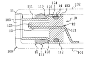
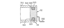
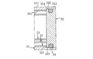
- FIG. 3 is a cross-sectional view taken along line AA in FIG. 2.
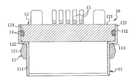
- FIG. 3 is a cross-sectional view taken along line BB in FIG. 2.
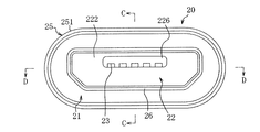
- FIG. 7 is a cross-sectional view taken along line CC in FIG. 6.
- FIG. 7 is a cross-sectional view taken along line DD in FIG. 6.
- the waterproof connector 10 for an electronic device according to the first embodiment of the present invention is mounted in an electronic device such as a portable small electronic device such as a multifunctional mobile phone, a multifunctional portable information terminal, a portable music player, and an electronic book reader. It is a waterproof connector conforming to the micro-USB standard.
- the waterproof connecting device 10 of the first embodiment has a seamless substantially cylindrical shell 11, and the shell 11 corresponds to a substantially cylindrical exterior body.
- a support portion 12 is mounted in a wall shape on the back side of the shell 11, and the support portion 12 supports a contact terminal 13 provided so as to be penetrated, and a front portion of the contact terminal 13 is introduced into the shell 11. Has been.
- the shell 11 is formed in a substantially rectangular tube shape without a seam, and a stepped portion 113 extending from the front part 111 on the male connector or plug insertion side to the rear part 112 having a height and width larger than the front part 111 is a circumferential surface. It is formed in a circumferential shape so as to bulge outward.
- the shell 11 is formed with a non-penetrating surface at least on the front side of the front surface of the support portion 12. In this example, the shell 11 is a non-penetrating surface having no penetrating portion over the entire front portion 111, stepped portion 113, and rear portion 112. Is formed.
- the support portion 12 is formed of an insulating hard resin and is provided in a wall shape so as to close the back side of the shell 11.
- the support portion 12 has a substantially rectangular parallelepiped main body 121 having a recess in the center, and is fitted to the rear portion 112 of the shell 11 so that a part of the front surface 122 of the main body 121 abuts the inner surface of the stepped portion 113.
- a circumferential concave portion 124 composed of a groove and a notch is formed in a part of the outer peripheral surface 123 of the support portion 12, and the O-ring 14 is fitted into the concave portion 124 so that the O-ring is supported on the support portion 12. 14 is provided.
- the O-ring 14 corresponds to a circumferential sealing portion
- the recess 124 corresponds to a stepped portion where the O-ring 14 can be placed.
- the O-ring 14 has a substantially circular peripheral shape in cross-sectional view formed of an elastic material such as rubber or soft resin, and is a part of the outer peripheral surface 123 of the support portion 12 before the support portion 12 is installed in the shell 11. A portion of the O-ring 14 is provided so as to protrude outward from the portion.
- the support portion 12 is press-fitted into the shell 11 so as to crush the protruding portion of the O-ring 14. In this embodiment, the support portion 12 is pressed into a position where the front surface 122 contacts the inner surface of the stepped portion 113.
- the O-ring 14 is circumferentially pressed against the inner surface of the shell 11.
- the O-ring 14 corresponding to the circumferential sealing portion that seals between the shell 11 corresponding to the exterior body and the support portion 12 is supported by the shell 11 at a position where the shell 11 and the support portion 12 are close to each other. It is provided between the parts 12.
- a plurality of contact terminals 13 are insert-molded and partially embedded in the support portion 12 and are provided so as to penetrate the main body 121, so that the contact terminals 13 have a watertight structure by insert molding. It is attached to the support part 12.
- the contact terminal 13 in the illustrated example is arranged along one side of the protruding portion 125 protruding forward of the support portion 12, introduced into the shell 11, and exposed in the shell 11 so as to be in contact with a terminal on the plug side or the like. At the same time, it is pulled out from the rear of the main body 121 and connected to a circuit board of an electronic device (not shown).
- an appropriate terminal of the plurality of contact terminals 13 can be a power supply terminal and a ground terminal that is conductively connected to the shell 11.
- a sealing material 15 is externally fitted so that one side surface is in circumferential contact with the stepped portion 113.
- the sealing material 15 is formed of a soft resin such as an elastomer in a ring shape having a substantially square frame shape, and has a protrusion 151 having a substantially chevron shape in cross section that protrudes outward from a main body having a substantially square shape in cross section.
- reference numeral 103 denotes an opening for inserting a connector such as a plug, which is provided on the side wall of the housing body 101.
- the waterproof connector 10 of the first embodiment can be manufactured by an appropriate method that can be manufactured.
- a metal plate 11 having a predetermined shape is formed by drawing and pressing a metal flat plate.
- the support 12 having a predetermined shape is formed by injection molding so that the contact terminal 13 is insert-molded, and the O-ring 14 is fitted into the recess 124 of the support 12.
- the support portion 12 provided with the O-ring 14 corresponding to the circumferential sealing portion is inserted into the shell 11 corresponding to the exterior body from the rear portion 112 side.
- the O-ring 14 protruding outward from a part of the outer peripheral surface 123 of the support portion 12 slides on the inner surface of the shell 11 so as to be crushed by the inner surface of the shell 11 and is press-fitted into the shell 11.
- the insertion of the support portion 12 is performed until the front surface 122 of the support portion 12 comes into contact with the inner surface of the stepped portion 113, and the inserted O-ring 14 is circumferentially pressed against the inner surface of the shell 11, and the shell 11 and the support portion are inserted.
- An O-ring 14 provided at a predetermined position between the shell 12 and the support portion 12 is sealed.
- the sealing material 15 is fitted into the outer periphery of the rear position of the front portion 111 so that the side surface is in contact with the stepped portion 113, whereby the waterproof connecting device 10 which is a waterproof connector is obtained. It is also possible to press-fit the support portion 12 into the shell 11 in which the sealing material 15 is previously fitted.
- the space between the shell 11 and the support portion 12 is sealed with the circumferential O-ring 14 to ensure the waterproof property between the shell 11 and the support portion 12. be able to. Therefore, it is not necessary to fix the filler to the inner surface of the shell 11 in the space on the back side of the shell 11, and the filler is peeled off from the inner surface of the shell 11 by the force applied intermittently, so that a gap is formed. There is no loss of sex. And since O-ring 14 is arrange
- the length of the waterproof connecting device 10 can be reduced and the size can be reduced. Therefore, the area occupied by the waterproof connector 10 can be reduced, the usable portion inside the electronic device can be increased, a more free layout design inside the electronic device can be realized, and the electronic device can be downsized.
- the support part 12 can be installed at a predetermined position in the shell 11 with high stability by press-fitting the support part 12 into the shell 11.
- the sealing portion is provided on the entire outer peripheral surface 123 of the support portion 12, the frictional resistance becomes very large when press-fitting into the shell 11, whereas a part of the outer peripheral surface 123 of the support portion 12 is provided.
- the O-ring 14 By providing the O-ring 14 on the inner surface, the frictional resistance at the time of press-fitting into the shell 11 can be reduced, and the assembling work can be facilitated.
- the structure in which the O-ring 14 is fitted into the support portion 12 in the sealing portion enables waterproof sealing to the shell 11 and the support portion 12 in various shapes and sizes at low cost, thereby improving versatility. Can do.
- the exterior body is a metal shell 11
- the resin filler and the exterior body are easily peeled off, and the possibility of impairing the waterproofing is increased.
- the O-ring 14 is pressed against the inner surface of the metal shell 11 in a circumferential shape, thereby providing a waterproof stability. Durability can be increased.
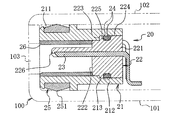
- the waterproof connector 20 for the electronic device according to the second embodiment of the present invention is also a portable small electronic device such as a multi-function mobile phone, a multi-function portable information terminal, a portable music player, and an electronic book reader.
- This is a waterproof connector complying with the micro-USB standard.
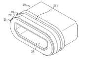
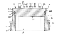
- the waterproof connecting device 20 of the second embodiment has a substantially cylindrical case 21 made of resin, and the case 21 corresponds to a substantially cylindrical exterior body.
- a support portion 22 is mounted in a wall shape on the back side of the case 21, and the support portion 22 supports a contact terminal 23 provided so as to be penetrated, and a front portion of the contact terminal 23 is introduced into the case 21.
- a metal shell 26 is mounted on the inner side of the case 21 in front of the closed portion by the support portion 22, and the front portion of the contact terminal 23 is disposed on the inner side of the shell 26. .
- the case 21 has a substantially square cylindrical shape and is formed of a hard resin such as a polycarbonate resin or an ABS resin.
- a concave groove 211 is formed on the front side of the case 21 along the outer peripheral surface, and a sealing material 25 to be described later is fitted into the concave groove 211 so as to be circumferentially provided.
- a stepped portion 213 is formed on the inner side near the rear portion 212 of the case 21, and the space inside the rear portion 212 of the case 21 is larger in height and width than the space inside the front portion. .
- the support portion 22 is formed of an insulating hard resin and is provided in a wall shape so as to close the back side of the case 21.
- the support portion 22 has a substantially rectangular parallelepiped main body 221, and a substantially square columnar stepped portion 222 is formed in the vicinity of the front end of the main body 221 so that the central region protrudes forward. It is designed to be fitted with the front part.
- the support portion 22 is fitted and fitted in the rear portion 212 of the case 21 such that the front surface 223 on the outer peripheral side of the step portion 222 is in contact with the inner surface of the step portion 213 of the case 21.
- a circumferential concave portion 225 constituted by a groove is formed in a part of the outer peripheral surface 224 of the support portion 22, and the O-ring 24 is fitted into the concave portion 225 to provide the O-ring 24 in the support portion 22. It has been.
- the O-ring 24 corresponds to a circumferential sealing portion
- the concave portion 225 corresponds to a step portion where the O-ring 24 can be placed.
- the O-ring 24 has a substantially circular circumferential shape in cross-sectional view made of an elastic material such as rubber or soft resin, and is a part of the outer peripheral surface 224 of the support portion 22 before the support portion 22 is installed in the case 21.
- a portion of the O-ring 24 is provided so as to protrude outward from the portion.
- the support portion 22 is press-fitted into the case 21 so as to crush the protruding portion of the O-ring 24.
- the support portion 22 is pressed into a position where the front surface 223 contacts the inner surface of the stepped portion 213.
- the O-ring 24 is pressed against the inner surface of the case 21 in a circumferential manner.
- the O-ring 24 corresponding to the circumferential sealing portion that seals between the case 21 corresponding to the exterior body and the support portion 22 is supported by the case 21 and the support portion 22 at a position where the case 21 and the support portion 22 are close to each other. It is provided between the parts 22.
- a plurality of contact terminals 23 are insert-molded and partially embedded in the support portion 22 so as to penetrate the main body 221, and the contact terminals 23 are insert-molded. It is attached to the support portion 22 so as to have a watertight structure.
- the contact terminal 23 in the illustrated example is arranged along one side of the protruding portion 226 that protrudes forward of the support portion 22 and is introduced into the case 21 and the shell 26 so as to be in contact with the terminal on the plug side or the like. And exposed in the shell 26, pulled out from the back of the main body 221, and connected to a circuit board of an electronic device (not shown).
- an appropriate terminal of the plurality of contact terminals 23 can be a power supply terminal and a ground terminal that is conductively connected to the shell 26.
- the sealing member 25 that is externally fitted around the case 21 is formed in a substantially square frame-shaped ring shape with a soft resin such as an elastomer, and is substantially in a cross-sectional view protruding outward from a substantially rectangular main body in a cross-sectional view. It has a Yamagata ridge 251.
- the protrusion 251 includes, for example, a housing main body 101 having a connector insertion opening 103 such as a plug constituting the housing 100 of the electronic device. It is pressed against the lid 102 and presses against the casing 100 in a circumferential shape, thereby forming a watertight structure (see FIG. 7).
- the waterproof connector 20 of the second embodiment can be manufactured by an appropriate method that can be manufactured.
- a case 21 having a predetermined shape is formed by injection molding, and the contact terminal 23 is formed.
- a support portion 22 having a predetermined shape is formed by injection molding so as to be insert-molded, and the O-ring 24 is fitted into the recess 225 of the support portion 22.
- the support portion 22 provided with the O-ring 24 corresponding to the circumferential sealing portion is inserted into the case 21 corresponding to the exterior body from the rear portion 212 side.
- the O-ring 24 protruding from the part of the outer peripheral surface 224 of the support portion 22 to the outer periphery slides on the inner surface of the case 21 so as to be crushed by the inner surface of the case 21 and is press-fitted into the case 21.
- the vicinity of the rear end of the rear portion 212 of the case 21 of this example is preferably formed in a tapered shape so as to expand toward the rear end in order to facilitate the insertion of the support portion 22.
- the support portion 22 is inserted until the front surface 223 of the support portion 22 comes into contact with the inner surface of the stepped portion 213 of the case 21, and the inserted O-ring 24 is pressed against the inner surface of the case 21 in a circumferential shape.
- An O-ring 24 provided at a predetermined position between the case 21 and the support portion 22 seals between the case 21 and the support portion 22.
- the shell 26 is inserted from the front so that the vicinity of the rear end of the shell 26 is fitted between the side surface of the stepped portion 222 of the support portion 22 and the inner surface of the case 21.
- the waterproof connector 20 which is a waterproof connector is obtained.
- the support portion 22 is press-fitted from the rear portion 212 side so that the vicinity of the rear end of the shell 26 is between the side surface of the stepped portion 222 of the support portion 22 and the inner surface of the case 21.
- a step of forming a fitted state or a step of press-fitting the support portion 22 and / or inserting the shell 26 in a state where the sealing material 25 is attached to the case 21 may be used.
- the case 21 and the support portion 22 are sealed with the circumferential O-ring 24 to ensure the waterproof property between the case 21 and the support portion 22. be able to. Therefore, it is not necessary to fix the filler to the inner surface of the case 21 in the space on the back side of the case 21, and the filler is peeled off from the inner surface of the case 21 by a force applied intermittently, so that a gap is formed. There is no loss of sex. And since O-ring 24 is arrange
- the length of the waterproof connecting device 20 can be shortened and the size can be reduced. Therefore, the area occupied by the waterproof connector 20 can be reduced, the usable portion inside the electronic device can be increased, a more flexible layout design inside the electronic device can be realized, and the electronic device can be downsized.
- the support part 22 can be installed at a predetermined position in the case 21 with high stability by press-fitting the support part 22 into the case 21.
- waterproofness can be secured even if an error occurs in the position of the O-ring 24 and the support portion 22 in the case 21, and there is a margin in the positional accuracy of the O-ring 24 and the support portion 22. Therefore, the manufacturing accuracy can be reduced by reducing the assembly accuracy, and the yield can be improved by reducing defective products. Further, by providing the O-ring 24 on a part of the outer peripheral surface 224 of the support portion 22, it is possible to reduce the frictional resistance during press-fitting into the case 21 and facilitate the assembling work.
- a waterproof connector 30 for an electronic device according to a third embodiment of the present invention is installed in an electronic device such as a portable small electronic device such as a multifunctional mobile phone, a multifunctional portable information terminal, or a portable music player.
- a multi-pole waterproof jack such as an earphone jack.
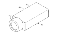
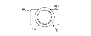
- the waterproof connecting device 30 of the third embodiment has a substantially cylindrical housing 31 made of resin, and the housing 31 corresponds to a substantially cylindrical exterior body.
- a support portion 32 is mounted in a wall shape on the back side of the housing 31, and the support portion 32 supports a contact terminal 33 provided so as to penetrate therethrough, and a front portion of the contact terminal 33 is introduced into the housing 31. ing.
- the housing 31 is made of a hard resin such as polycarbonate resin or ABS resin, the main body 311 of the housing 31 has a substantially rectangular tube shape, and the front portion 312 on the plug insertion side has a substantially cylindrical shape. On the inner surface of the rear portion 313 of the main body 311, a step surface 314 with which the support portion 32 abuts is formed.
- the support part 32 is formed of a substantially rectangular parallelepiped insulating hard resin, is provided in a wall shape so as to close the back side of the housing 31, and the periphery of the front surface 321 of the support part 32 is a step difference of the housing 31.
- the housing 31 is fitted and fitted in the rear portion 313 so as to contact the surface 314.
- a circumferential recess 323 constituted by a groove is formed in a part of the outer peripheral surface 322 of the support portion 32, and an O-ring 34 is fitted in the recess 323, and the O-ring 34 is provided in the support portion 32.
- the O-ring 34 corresponds to a circumferential sealing portion
- the concave portion 323 corresponds to a step portion where the O-ring 34 can be placed.
- the O-ring 34 has a substantially circular peripheral shape in cross-sectional view formed of an elastic material such as rubber or soft resin, and is a part of the outer peripheral surface 322 of the support portion 32 before the support portion 32 is installed in the housing 31.
- a part of the O-ring 34 is provided so as to protrude from the portion to the outer periphery.
- the support portion 32 is press-fitted into the housing 31 so that the protruding portion of the O-ring 34 is crushed.
- the support portion 32 is press-fitted into a position where the front surface 321 contacts the step surface 314.
- the ring 34 is circumferentially pressed against the inner surface of the housing 31.
- the O-ring 34 corresponding to a circumferential sealing portion that seals between the housing 31 corresponding to the exterior body and the support portion 32 is supported by the housing 31 at a position where the housing 31 and the support portion 32 are close to each other. It is provided between the unit 32.
- the contact terminal 33 supported by the support portion 32 is provided so as to penetrate the plate spring-like contact terminal portion 331 that contacts the plug-side terminal at the tip contact point and the support portion 32.
- an extension terminal portion 332 supported by the support portion 32 is housed in the housing 31 so as to be partially fitted in a mounting groove (not shown) formed in the housing 31.
- Each extension terminal portion 332 is insert-molded and partially embedded in the support portion 32, and is attached to the support portion 32 so as to have a watertight structure by insert molding.
- each extended terminal portion 332 partially exposed on the front side of the support portion 32 and each corresponding contact housed in the housing 31.
- the terminal portion 331 is conductively connected, and each contact terminal 33 is configured.
- the structure in which the extension terminal portion 332 and the contact terminal portion 331 are conductively connected is formed, for example, by forming an engagement hole in which the tip of the extension terminal portion 332 is exposed on the front side of the support portion 32 and contacting the engagement hole.
- a configuration in which either the front end of the extension terminal portion 332 or the rear end of the contact terminal portion 331 is formed into a leaf spring shape and connected to the other by elastic contact can be employed.
- each contact terminal 33 integrally, it is also possible to insert the rear part in the support part 32, and to be provided so that it may penetrate to the support part 32.
- the contact terminal 33 is housed in the housing 31 so as to be inserted into the mounting groove of the housing 31.
- the contact terminal 33 is provided in the housing 31 so as to be in contact with the terminal on the plug side so as to be in contact with the terminal on the tip, and is pulled out from the rear of the support portion 32 and connected to a circuit board of an electronic device (not shown). Is done.
- the waterproof connector 30 which is a waterproof jack configured as described above is mounted and attached to the casing 100 of the electronic device, as in the first and second embodiments.
- the waterproof connecting device 30 of the third embodiment can be manufactured by an appropriate method that can be manufactured.
- the housing 31 having a predetermined shape is formed by injection molding, and the contact terminal 33 is formed.
- a support portion 32 having a predetermined shape is formed by injection molding so that the extension terminal portion 332 or the contact terminal 33 is insert-molded, and the O-ring 34 is fitted into the concave portion 323 of the support portion 32.
- the support portion 32 provided with the O-ring 34 corresponding to the circumferential sealing portion is inserted into the housing 31 corresponding to the exterior body from the rear portion 313 side.
- the O-ring 34 protruding outward from a part of the outer peripheral surface 322 of the support portion 32 slides on the inner surface of the housing 31 so as to be crushed by the inner surface of the housing 31 and is press-fitted into the housing 31.
- the support portion 32 is inserted until the front surface 321 of the support portion 32 comes into contact with the stepped surface 314 of the housing 31, and the inserted O-ring 34 is circumferentially pressed against the inner surface of the housing 31, and the housing 31 and the support portion are inserted.
- the O-ring 34 provided at a predetermined position between the housing 31 and the support portion 32 is sealed. Thereby, the waterproof connector 30 which is a multipolar waterproof jack is obtained.
- the support terminal 32 is mounted after the contact terminal portion 331 is installed in the housing 31 before the step of inserting the support portion 32.
- the contact terminal portion 331 and the extension terminal portion 332 insert-molded on the support portion 32 are brought into pressure contact and conductively connected when inserted and inserted to a predetermined position.
- the vicinity of the rear end of the housing 31 may be formed in a tapered shape so as to expand toward the rear end in order to facilitate the insertion of the support portion 32 as in the first and second embodiments.
- the space between the housing 31 and the support portion 32 is sealed by the circumferential O-ring 34 to ensure the waterproof property between the housing 31 and the support portion 32. be able to. Therefore, it is not necessary to fix the filler to the inner surface of the housing 31 in the space on the back side of the housing 31, and the filler is peeled off from the inner surface of the housing 31 by a force applied intermittently, so that a gap is formed. There is no loss of sex. And since O-ring 34 is arrange
- the length of the waterproof connecting device 30 can be reduced and the size can be reduced. Therefore, the area occupied by the waterproof connector 30 can be reduced, the usable portion inside the electronic device can be increased, a more flexible layout design inside the electronic device can be realized, and the electronic device can be downsized.
- the elastic O-ring 34 can follow the inner surface of the housing 31 to maintain waterproofness.
- the support part 32 can be installed at a predetermined position in the housing 31 with high stability by press-fitting the support part 32 into the housing 31.
- the O-rings 14, 24, and 34 are used for the circumferential sealing portion.
- the circumferential sealing portion according to the present invention includes a space between the outer package and the support portion. It is possible to use an appropriate one provided at a predetermined position and capable of sealing between the exterior body and the support portion.
- FIG. 13 shows a waterproof connector 10a of a modification of the first embodiment.
- an elastic resin formed of an elastic resin at a portion corresponding to the recess 124 of the support 12a.
- a sealing portion 16a is provided.
- the elastic resin sealing portion 16a is integrally fixed to the support portion 12a formed of hard resin, and has a protruding portion from the outer peripheral surface 123 of the support portion 12a in the outer peripheral direction. In the state in which the support portion 12a is press-fitted into the shell 11, the elastic resin sealing portion 16a is press-fitted to the inner surface of the shell 11 in a circumferential shape by pressing the protruding portion of the elastic resin sealing portion 16a with the shell 11.
- the configuration in which the circumferential sealing portion is provided is not limited to the configuration in which the sealing portion is provided so as to protrude outward from the outer peripheral surface of the support portion, for example, the configuration in which the sealing portion is provided so as to protrude to the front side of the support portion, Alternatively, a configuration in which a circumferential sealing portion is provided so as to protrude on both the front side and the outer circumferential side of the support portion can be employed.
- FIG. 14 shows a waterproof connection device 10b according to a modification of the first embodiment.
- a waterproof double-sided surface is provided as a circumferential sealing portion on the front surface 122 of the support portion 12b.
- a tape 17b is provided.
- the waterproof double-sided tape 17b has one surface circumferentially bonded to the front surface 122 of the support portion 12b, and the other surface circumferentially bonded to the inner surface of the step portion 115 of the shell 11 corresponding to the exterior body.
- a waterproof double-sided tape 17b whose front surface is an adhesive surface is inserted into the shell 11 with a support 12b provided on the front side, and the front surface of the waterproof double-sided tape 17b is connected to the inner surface of the stepped portion 115 of the shell 11. It is formed by abutting on and adhering circumferentially.
- Other configurations are basically the same as those in the first embodiment.
- the waterproof double-sided tape 17b on the front side of the support portion 12b is inserted and bonded until it contacts the stepped portion 115 of the shell 11, whereby the support portion 12b and the waterproof double-sided tape 17b are accurately positioned within the shell 11. It can arrange
- attached on the shell 11 is appropriate, for example, the elastic resin sealing integrated with the support part 12b so that it may protrude in the front side of the support part 12b It is possible to have a configuration in which a portion is provided and the front side is bonded to the inner surface of the stepped portion 115 of the shell 11.
- the front surface side of the support portion where the sealing portion is provided includes an appropriate surface positioned facing the front of the support portion, and in addition to the front surface 122 of the support portion 12b, for example, in the vicinity of the outer periphery of the front surface 122
- transformation which provides the circumferential sealing part in the front side of a support part is applicable also suitably about 2nd, 3rd embodiment.
- a circumferential sealing portion may be provided in advance on the exterior body side, and a support portion may be inserted into the exterior body so that the support portion is pressed against or adhered to the circumferential sealing portion.
- a circumferential O-ring is fitted to a corner portion formed by the step portion 115 and the rear portion 113 of the shell 11, and a support portion having a circumferential recess portion formed by a notch is formed on the shell 11.
- the present invention can be used as a waterproof connector used for electrical connection of various electronic devices such as a multifunctional mobile phone, a multifunctional portable information terminal, a portable music player, and an electronic book reader.
Landscapes
- Chemical & Material Sciences (AREA)
- Dispersion Chemistry (AREA)
- Connector Housings Or Holding Contact Members (AREA)
Abstract
Description
これによれば、外装体と支持部との間を周状の封止部で封止して、外装体と支持部との間の防水性を確保することができる。従って、外装体の奥側の空間で充填材を外装体内面と固着することが不要となり、この充填材が断続的に加えられる力で外装体内面から剥離して隙間ができ、防水性が損なわれることがなくなる。そして、周状の封止部は、外装体と支持部との間に挟み込まれるように配置されることから、外装体と内装される支持部の間から奥側に水が浸入することを高い耐久性で確実に防止することができる。また、外装体の奥側の充填材充填用空間が不要となることから、防水接続器具の長さを短くして小型化することができる。従って、防水接続器具の占有面積を小さくし、電子機器内部の使用可能部分を増やすことが可能となり、電子機器内部のより自由なレイアウト設計の実現、電子機器の小型化を図ることができる。
これによれば、外装体に部分的に或いは全体的に膨らませる力が加わり、外装体に一時的或いは恒久的な変形が生じた場合にも、外装体内面に圧接されている弾性素材の封止部が外装体内面に追従して防水性を維持することができる。また、封止部を圧接する支持部を外装体内に圧入することにより、外装体内の所定位置に支持部を高い安定性で設置することができる。
これによれば、外周に突出する封止部を外装体内に圧入するようにして支持部、封止部を外装体内に設置することが可能となる。このように設置される構造では、外装体内での封止部、支持部の位置に誤差が生じても外装体と支持部の間の封止がなされて防水性を確保することができ、封止部、支持部の位置精度に余裕を持たせることができる。従って、組立精度を緩和して製造コストを低減することができると共に、不良品を減らして歩留まりを向上することができる。また、支持部の外周面の全体に封止部を設けた場合、外装体への圧入の際に摩擦抵抗が非常に大きくなるのに対して、支持部の外周面の一部に封止部を設けることにより、外装体への圧入の際の摩擦抵抗を減らし、組立作業を容易にすることができる。
これによれば、低コストで、多様な形状、サイズの外装体や支持部に、外装体と支持部との間の防水封止を行うことができ、汎用性を高めることができる。
これによれば、封止部と支持部との間から水が浸入することが全くなくなり、外装体と支持部との間の封止による防水性を一層高めることができる。
これによれば、外装体が金属製である場合に、外装体の奥部の周壁と支持部とで形成される空間に樹脂充填材を設ける構造では、外装体が樹脂である場合に比べて樹脂充填材と外装体が剥離しやすく、防水性が損なわれる可能性が高くなるのに対し、金属製の外装体の内面に封止部を周状に圧接することにより、防水の安定性、耐久性を高めることができる。
これによれば、支持部の前面側の封止部を外装体の段差部に当接するまで挿入して接着することにより、支持部及び封止部を外装体内の正確な位置に配置して防水封止を行うことができ、製品の均一性を高めることができる。
これによれば、低コストで、多様な形状、サイズの外装体や支持部に、外装体と支持部との間の防水封止を行うことができ、汎用性を高めることができる。
これによれば、本発明の電子機器の防水接続器具の効果を奏する電子機器を得ることができる。
本発明による第1実施形態の電子機器の防水接続器具10は、例えば多機能携帯電話機、多機能携帯情報端末、携帯用音楽プレーヤー、電子書籍リーダーなど携帯型小型電子機器等の電子機器に内装されるものであり、micro―USB規格準拠等の防水コネクタである。
本発明による第2実施形態の電子機器の防水接続器具20も、第1実施形態と同様、例えば多機能携帯電話機、多機能携帯情報端末、携帯用音楽プレーヤー、電子書籍リーダーなど携帯型小型電子機器等の電子機器に内装されるものであり、micro―USB規格準拠等の防水コネクタである。
本発明による第3実施形態の電子機器の防水接続器具30は、例えば多機能携帯電話機、多機能携帯情報端末、携帯用音楽プレーヤーなど携帯型小型電子機器等の電子機器に内装されるものであり、イヤホンジャック等の多極の防水ジャックである。
本明細書開示の発明は、各発明、各実施形態の構成の他に、適用可能な範囲で、これらの部分的な構成を本明細書開示の他の構成に変更して特定したもの、或いはこれらの構成に本明細書開示の他の構成を付加して特定したもの、或いはこれらの部分的な構成を部分的な作用効果が得られる限度で削除して特定した上位概念化したものを含むものである。そして、下記変形例も包含する。
Claims (9)
- 略筒状の外装体と、
前記外装体の奥側に壁状に内装される支持部と、
前記支持部で支持されて前記外装体内に導入されているコンタクト端子と、
前記外装体と前記支持部とが近接する位置で前記外装体と前記支持部との間に設けられ、前記外装体と前記支持部との間を封止する周状の封止部と
を備えることを特徴とする電子機器の防水接続器具。 - 前記封止部が弾性素材で形成されて前記支持部に設けられており、
前記封止部を前記外装体の内面に周状に圧接するようにして前記支持部が前記外装体内に圧入されていることを特徴とする請求項1記載の電子機器の防水接続器具。 - 前記支持部の外周面の一部から外側への突出部分を圧入して前記封止部が設けられていることを特徴とする請求項2記載の電子機器の防水接続器具。
- 前記封止部がオーリングであり、前記オーリングが前記支持部の定置可能な段差箇所に嵌め込まれていることを特徴とする請求項2又は3記載の電子機器の防水接続器具。
- 前記封止部が前記支持部と一体化している弾性樹脂で形成されていることを特徴とする請求項2又は3記載の電子機器の防水接続器具。
- 前記外装体が金属製であることを特徴とする請求項2~5の何れかに記載の電子機器の防水接続器具。
- 前記封止部が、前記支持部の前面側に設けられ、前記外装体の段差部に周状に接着されていることを特徴とする請求項1記載の電子機器の防水接続器具。
- 前記封止部が、前記支持部の前面側に一方の面を、前記外装体の段差部に他方の面を接着される防水両面テープであることを特徴とする請求項7記載の電子機器の防水接続器具。
- 請求項1~8の何れかに記載の電子機器の防水接続器具が筐体に内装されていることを特徴とする電子機器。
Priority Applications (5)
| Application Number | Priority Date | Filing Date | Title |
|---|---|---|---|
| EP19181015.9A EP3561965B1 (en) | 2014-05-26 | 2015-05-11 | Waterproof connection apparatus for electronic equipment, and electronic equipment |
| US15/309,943 US10027052B2 (en) | 2014-05-26 | 2015-05-11 | Waterproof connection apparatus for electronic equipment, and electronic equipment |
| CN201580027552.4A CN106415943A (zh) | 2014-05-26 | 2015-05-11 | 电子设备的防水连接器具及电子设备 |
| KR1020167032729A KR101851997B1 (ko) | 2014-05-26 | 2015-05-11 | 전자기기의 방수 접속기구 및 전자기기 |
| EP15800158.6A EP3151346A4 (en) | 2014-05-26 | 2015-05-11 | Waterproof connection apparatus for electronic equipment, and electronic equipment |
Applications Claiming Priority (2)
| Application Number | Priority Date | Filing Date | Title |
|---|---|---|---|
| JP2014108087A JP2015225712A (ja) | 2014-05-26 | 2014-05-26 | 電子機器の防水接続器具及び電子機器 |
| JP2014-108087 | 2014-05-26 |
Publications (1)
| Publication Number | Publication Date |
|---|---|
| WO2015182049A1 true WO2015182049A1 (ja) | 2015-12-03 |
Family
ID=54698408
Family Applications (1)
| Application Number | Title | Priority Date | Filing Date |
|---|---|---|---|
| PCT/JP2015/002380 Ceased WO2015182049A1 (ja) | 2014-05-26 | 2015-05-11 | 電子機器の防水接続器具及び電子機器 |
Country Status (6)
| Country | Link |
|---|---|
| US (1) | US10027052B2 (ja) |
| EP (2) | EP3561965B1 (ja) |
| JP (1) | JP2015225712A (ja) |
| KR (1) | KR101851997B1 (ja) |
| CN (1) | CN106415943A (ja) |
| WO (1) | WO2015182049A1 (ja) |
Cited By (2)
| Publication number | Priority date | Publication date | Assignee | Title |
|---|---|---|---|---|
| EP3429170A4 (en) * | 2016-03-29 | 2019-03-27 | Huawei Technologies Co., Ltd. | CONNECTION FOR MOBILE TERMINAL AND MOBILE TERMINAL |
| US20220231449A1 (en) * | 2021-01-19 | 2022-07-21 | Bittium Biosignals Oy | Holder apparatus of bio-signal device and method of assembling holder apparatus |
Families Citing this family (23)
| Publication number | Priority date | Publication date | Assignee | Title |
|---|---|---|---|---|
| US10826255B2 (en) * | 2013-07-19 | 2020-11-03 | Foxconn Interconnect Technology Limited | Flippable electrical connector |
| JP5925865B1 (ja) * | 2014-11-14 | 2016-05-25 | 日本航空電子工業株式会社 | 防水コネクタ |
| JP2017208193A (ja) * | 2016-05-17 | 2017-11-24 | 日本圧着端子製造株式会社 | 防水コネクタ |
| CN108232699B (zh) * | 2016-12-15 | 2020-10-30 | 富士康(昆山)电脑接插件有限公司 | 电连接器 |
| CN107026359B (zh) * | 2017-02-27 | 2019-02-22 | Oppo广东移动通信有限公司 | 防水套、连接装置及移动终端 |
| JP6230013B1 (ja) * | 2017-04-07 | 2017-11-15 | Smk株式会社 | 電気コネクタ |
| TWI635667B (zh) * | 2017-08-08 | 2018-09-11 | 祥峰實業股份有限公司 | 可提昇防水係數的高速信號傳輸連接器 |
| KR101951677B1 (ko) * | 2017-08-22 | 2019-02-25 | 엘지전자 주식회사 | 커넥터 방수 하우징 및 이동 단말기 |
| CN109428190B (zh) * | 2017-08-25 | 2021-10-26 | 富士康(昆山)电脑接插件有限公司 | 电连接器组合及其制造方法 |
| KR101947952B1 (ko) | 2018-04-02 | 2019-02-13 | 고영상 | 착탈 가능한 확장형 기능 모듈이 구비된 휴대용 통신기기 |
| WO2019220718A1 (ja) * | 2018-05-17 | 2019-11-21 | 日立オートモティブシステムズ株式会社 | 電子制御装置 |
| JP6624241B2 (ja) * | 2018-06-13 | 2019-12-25 | 富士電機機器制御株式会社 | 配線用接続器具、電気機器及び回路遮断器 |
| US11101595B2 (en) * | 2018-06-27 | 2021-08-24 | Lg Electronics Inc. | Mobile terminal |
| US10276972B1 (en) * | 2018-08-14 | 2019-04-30 | Avertronics, Inc. | Power connector |
| CN111009777B (zh) * | 2018-10-08 | 2023-01-24 | 富顶精密组件(深圳)有限公司 | 电连接器及其制造方法 |
| JP6953485B2 (ja) * | 2019-08-30 | 2021-10-27 | 矢崎総業株式会社 | コネクタの防水シール構造 |
| DE102020204913A1 (de) * | 2020-04-17 | 2021-10-21 | Te Connectivity Germany Gmbh | Miniaturisierter Stecker |
| TWI759038B (zh) * | 2020-12-28 | 2022-03-21 | 唐虞企業股份有限公司 | 連接器總成及其連接器 |
| WO2022153136A1 (en) * | 2021-01-12 | 2022-07-21 | Cochlear Limited | Electrical connector with multiple seals inhibiting liquid ingress |
| CN215299625U (zh) * | 2021-04-26 | 2021-12-24 | 富士康(昆山)电脑接插件有限公司 | 电连接器 |
| CN113613446B (zh) | 2021-07-01 | 2022-09-23 | 荣耀终端有限公司 | 终端设备 |
| CN115498441B (zh) * | 2022-09-23 | 2026-01-09 | 珠海格力电器股份有限公司 | 电连接接口、电连接座及用电设备 |
| JP2024120303A (ja) * | 2023-02-24 | 2024-09-05 | 住友電装株式会社 | コネクタ装置 |
Citations (8)
| Publication number | Priority date | Publication date | Assignee | Title |
|---|---|---|---|---|
| JPH05507810A (ja) * | 1990-06-20 | 1993-11-04 | ローベルト ボツシユ ゲゼルシヤフト ミツト ベシユレンクテル ハフツング | 電気装置 |
| JP2007258041A (ja) * | 2006-03-24 | 2007-10-04 | Tyco Electronics Amp Kk | 防水型電気コネクタ |
| JP2011071876A (ja) * | 2009-09-28 | 2011-04-07 | Sony Ericsson Mobilecommunications Japan Inc | 携帯端末装置および筐体防水構造 |
| US7922535B1 (en) * | 2010-11-05 | 2011-04-12 | Cheng Uei Precision Industry Co., Ltd. | Electrical connector |
| JP2012009358A (ja) * | 2010-06-25 | 2012-01-12 | Jst Mfg Co Ltd | コネクタ用シールドケース及び電気コネクタ |
| JP2012238481A (ja) * | 2011-05-12 | 2012-12-06 | Molex Inc | 防水コネクタ |
| US8388380B1 (en) * | 2011-10-20 | 2013-03-05 | Hon Hai Precision Ind. Co., Ltd | Waterproof connector with board-mounted soldering plate for improved sealing |
| JP2013048019A (ja) * | 2011-08-29 | 2013-03-07 | Jst Mfg Co Ltd | 防水型コネクタ |
Family Cites Families (29)
| Publication number | Priority date | Publication date | Assignee | Title |
|---|---|---|---|---|
| US4976634A (en) * | 1989-08-31 | 1990-12-11 | Amp Incorporated | Means and method of securing an insert in a shell |
| JP3097367B2 (ja) | 1991-12-25 | 2000-10-10 | 住友電装株式会社 | 防水シールドコネクタ |
| JP2881430B2 (ja) * | 1993-12-24 | 1999-04-12 | 山一電機 株式会社 | シールドコネクタ組立体 |
| JP3753363B2 (ja) * | 2000-02-29 | 2006-03-08 | 矢崎総業株式会社 | コネクタ |
| JP2002134219A (ja) * | 2000-10-30 | 2002-05-10 | Yazaki Corp | 防水コネクタ及び該防水コネクタの製造方法 |
| JP3966407B2 (ja) * | 2002-09-24 | 2007-08-29 | 矢崎総業株式会社 | 防油水性を備えた電磁波シールド構造 |
| TW549710U (en) * | 2002-11-15 | 2003-08-21 | Hon Hai Prec Ind Co Ltd | Cable end connector assembly |
| JP2005019188A (ja) * | 2003-06-26 | 2005-01-20 | Auto Network Gijutsu Kenkyusho:Kk | 機器用コネクタ |
| JP4220880B2 (ja) * | 2003-10-17 | 2009-02-04 | 住友重機械工業株式会社 | 防水型端子台ユニット |
| CN2773936Y (zh) * | 2004-12-30 | 2006-04-19 | 富士康(昆山)电脑接插件有限公司 | 电连接器 |
| KR101315475B1 (ko) * | 2007-06-04 | 2013-10-04 | 타이코에이엠피(유) | 이동통신 단말기용 접속모듈 |
| EP2234217A4 (en) * | 2008-01-15 | 2011-06-29 | Fujikura Ltd | WATERTIGHT CONNECTOR FOR FLEXIBLE SUBSTRATE |
| US8025530B2 (en) * | 2008-07-14 | 2011-09-27 | Savi Technology, Inc. | Method and apparatus involving a housing with a sealed electrical connector |
| JP5528007B2 (ja) * | 2009-05-13 | 2014-06-25 | 矢崎総業株式会社 | シールド電線の固定構造およびその固定方法 |
| US8092252B2 (en) * | 2010-05-31 | 2012-01-10 | Cheng Uei Precision Industry Co., Ltd. | Electrical connector |
| JP2012009357A (ja) | 2010-06-25 | 2012-01-12 | Jst Mfg Co Ltd | 電気コネクタ |
| JP5673457B2 (ja) * | 2011-01-19 | 2015-02-18 | 日立金属株式会社 | コネクタ |
| JP5758640B2 (ja) * | 2011-02-04 | 2015-08-05 | 株式会社フロウエル | チューブ継手 |
| JP5689000B2 (ja) | 2011-03-16 | 2015-03-25 | 株式会社エクセル電子 | 電子機器のコネクタ、電子機器のプラグ及び電子機器の防水構造 |
| JP5801705B2 (ja) * | 2011-12-22 | 2015-10-28 | 矢崎総業株式会社 | 防水コネクタ接続構造 |
| CN202585914U (zh) * | 2012-03-26 | 2012-12-05 | 富士康(昆山)电脑接插件有限公司 | 电连接器 |
| US8696383B2 (en) * | 2012-09-11 | 2014-04-15 | Apple Inc. | Connector ground shield mechanical attachment |
| TWM456609U (zh) * | 2012-10-04 | 2013-07-01 | Asian Power Devices Inc | 電連接器組合 |
| KR20140061942A (ko) | 2012-11-14 | 2014-05-22 | 타이코에이엠피(유) | 접속모듈 |
| WO2014077502A1 (ko) * | 2012-11-14 | 2014-05-22 | 타이코에이엠피(유) | 접속모듈 |
| JP2015053177A (ja) * | 2013-09-06 | 2015-03-19 | 矢崎総業株式会社 | コネクタ |
| CN104868290A (zh) * | 2014-02-20 | 2015-08-26 | 安普泰科电子韩国有限公司 | 插座组件 |
| TWM484217U (zh) * | 2014-02-26 | 2014-08-11 | Advanced Connectek Inc | 防水型插座電連接器 |
| CN105449443B (zh) * | 2015-02-11 | 2018-03-06 | 富士康(昆山)电脑接插件有限公司 | 电连接器及其制造方法 |
-
2014
- 2014-05-26 JP JP2014108087A patent/JP2015225712A/ja active Pending
-
2015
- 2015-05-11 CN CN201580027552.4A patent/CN106415943A/zh active Pending
- 2015-05-11 KR KR1020167032729A patent/KR101851997B1/ko active Active
- 2015-05-11 WO PCT/JP2015/002380 patent/WO2015182049A1/ja not_active Ceased
- 2015-05-11 EP EP19181015.9A patent/EP3561965B1/en active Active
- 2015-05-11 EP EP15800158.6A patent/EP3151346A4/en not_active Withdrawn
- 2015-05-11 US US15/309,943 patent/US10027052B2/en active Active
Patent Citations (8)
| Publication number | Priority date | Publication date | Assignee | Title |
|---|---|---|---|---|
| JPH05507810A (ja) * | 1990-06-20 | 1993-11-04 | ローベルト ボツシユ ゲゼルシヤフト ミツト ベシユレンクテル ハフツング | 電気装置 |
| JP2007258041A (ja) * | 2006-03-24 | 2007-10-04 | Tyco Electronics Amp Kk | 防水型電気コネクタ |
| JP2011071876A (ja) * | 2009-09-28 | 2011-04-07 | Sony Ericsson Mobilecommunications Japan Inc | 携帯端末装置および筐体防水構造 |
| JP2012009358A (ja) * | 2010-06-25 | 2012-01-12 | Jst Mfg Co Ltd | コネクタ用シールドケース及び電気コネクタ |
| US7922535B1 (en) * | 2010-11-05 | 2011-04-12 | Cheng Uei Precision Industry Co., Ltd. | Electrical connector |
| JP2012238481A (ja) * | 2011-05-12 | 2012-12-06 | Molex Inc | 防水コネクタ |
| JP2013048019A (ja) * | 2011-08-29 | 2013-03-07 | Jst Mfg Co Ltd | 防水型コネクタ |
| US8388380B1 (en) * | 2011-10-20 | 2013-03-05 | Hon Hai Precision Ind. Co., Ltd | Waterproof connector with board-mounted soldering plate for improved sealing |
Non-Patent Citations (1)
| Title |
|---|
| See also references of EP3151346A4 * |
Cited By (3)
| Publication number | Priority date | Publication date | Assignee | Title |
|---|---|---|---|---|
| EP3429170A4 (en) * | 2016-03-29 | 2019-03-27 | Huawei Technologies Co., Ltd. | CONNECTION FOR MOBILE TERMINAL AND MOBILE TERMINAL |
| US20220231449A1 (en) * | 2021-01-19 | 2022-07-21 | Bittium Biosignals Oy | Holder apparatus of bio-signal device and method of assembling holder apparatus |
| US11682856B2 (en) * | 2021-01-19 | 2023-06-20 | Bittium Biosignals Oy | Holder apparatus of bio-signal device and method of assembling holder apparatus |
Also Published As
| Publication number | Publication date |
|---|---|
| US10027052B2 (en) | 2018-07-17 |
| EP3151346A4 (en) | 2017-11-22 |
| US20170250495A1 (en) | 2017-08-31 |
| EP3561965B1 (en) | 2020-10-28 |
| JP2015225712A (ja) | 2015-12-14 |
| KR20160145190A (ko) | 2016-12-19 |
| CN106415943A (zh) | 2017-02-15 |
| EP3561965A1 (en) | 2019-10-30 |
| EP3151346A1 (en) | 2017-04-05 |
| KR101851997B1 (ko) | 2018-04-25 |
Similar Documents
| Publication | Publication Date | Title |
|---|---|---|
| WO2015182049A1 (ja) | 電子機器の防水接続器具及び電子機器 | |
| KR102460726B1 (ko) | 커넥터 어셈블리 | |
| JP6053883B1 (ja) | 防水コネクタ及び電子機器 | |
| US9761988B1 (en) | Waterproof electric connector assembly | |
| CN102469723B (zh) | 连接器防水结构及使用其的便携式电子装置 | |
| EP3916928B1 (en) | Female connector, electronic device, and manufacturing method for female connector | |
| WO2014054426A1 (ja) | 携帯機器用アダプタ | |
| JP4873358B2 (ja) | 基板接続コネクタの防水取付け構造 | |
| CN109524826B (zh) | 模块用连接器 | |
| US20140342599A1 (en) | Electrical connector device | |
| US10446972B2 (en) | Electrical connector | |
| US10367293B1 (en) | Electrical connector | |
| WO2013170961A1 (en) | Electric connector | |
| JP5638932B2 (ja) | 電子部品内蔵コネクタ | |
| TWI511389B (zh) | 電連接器及電子裝置 | |
| KR102210023B1 (ko) | 커넥터 어셈블리 | |
| CN107251335A (zh) | 防水连接器 | |
| JP4873357B2 (ja) | 基板接続コネクタの防水取付け構造 | |
| WO2016035246A1 (ja) | 防水ジャック及びその取付構造並びに電子機器 | |
| JP2014216826A (ja) | シール性を有する接続構造 | |
| KR20160053746A (ko) | 오디오 잭 및 이를 구비하는 단말기 | |
| KR20170065204A (ko) | 커넥터 및 이를 구비한 전자기기 | |
| JPH0733056U (ja) | 音響部品の筐体取り付け構造および接続構造 |
Legal Events
| Date | Code | Title | Description |
|---|---|---|---|
| 121 | Ep: the epo has been informed by wipo that ep was designated in this application |
Ref document number: 15800158 Country of ref document: EP Kind code of ref document: A1 |
|
| REEP | Request for entry into the european phase |
Ref document number: 2015800158 Country of ref document: EP |
|
| WWE | Wipo information: entry into national phase |
Ref document number: 2015800158 Country of ref document: EP |
|
| WWE | Wipo information: entry into national phase |
Ref document number: 15309943 Country of ref document: US |
|
| ENP | Entry into the national phase |
Ref document number: 20167032729 Country of ref document: KR Kind code of ref document: A |
|
| NENP | Non-entry into the national phase |
Ref country code: DE |
|
| WWE | Wipo information: entry into national phase |
Ref document number: IDP00201608945 Country of ref document: ID |