WO2015186172A1 - 回転アクチュエータ - Google Patents
回転アクチュエータ Download PDFInfo
- Publication number
- WO2015186172A1 WO2015186172A1 PCT/JP2014/064606 JP2014064606W WO2015186172A1 WO 2015186172 A1 WO2015186172 A1 WO 2015186172A1 JP 2014064606 W JP2014064606 W JP 2014064606W WO 2015186172 A1 WO2015186172 A1 WO 2015186172A1
- Authority
- WO
- WIPO (PCT)
- Prior art keywords
- fixing member
- fixed
- shaft
- rotation output
- rotation
- Prior art date
- Legal status (The legal status is an assumption and is not a legal conclusion. Google has not performed a legal analysis and makes no representation as to the accuracy of the status listed.)
- Ceased
Links
Images
Classifications
-
- H—ELECTRICITY
- H02—GENERATION; CONVERSION OR DISTRIBUTION OF ELECTRIC POWER
- H02K—DYNAMO-ELECTRIC MACHINES
- H02K7/00—Arrangements for handling mechanical energy structurally associated with dynamo-electric machines, e.g. structural association with mechanical driving motors or auxiliary dynamo-electric machines
- H02K7/10—Structural association with clutches, brakes, gears, pulleys or mechanical starters
- H02K7/116—Structural association with clutches, brakes, gears, pulleys or mechanical starters with gears
-
- F—MECHANICAL ENGINEERING; LIGHTING; HEATING; WEAPONS; BLASTING
- F16—ENGINEERING ELEMENTS AND UNITS; GENERAL MEASURES FOR PRODUCING AND MAINTAINING EFFECTIVE FUNCTIONING OF MACHINES OR INSTALLATIONS; THERMAL INSULATION IN GENERAL
- F16H—GEARING
- F16H1/00—Toothed gearings for conveying rotary motion
- F16H1/28—Toothed gearings for conveying rotary motion with gears having orbital motion
-
- F—MECHANICAL ENGINEERING; LIGHTING; HEATING; WEAPONS; BLASTING
- F16—ENGINEERING ELEMENTS AND UNITS; GENERAL MEASURES FOR PRODUCING AND MAINTAINING EFFECTIVE FUNCTIONING OF MACHINES OR INSTALLATIONS; THERMAL INSULATION IN GENERAL
- F16H—GEARING
- F16H1/00—Toothed gearings for conveying rotary motion
- F16H1/28—Toothed gearings for conveying rotary motion with gears having orbital motion
- F16H1/32—Toothed gearings for conveying rotary motion with gears having orbital motion in which the central axis of the gearing lies inside the periphery of an orbital gear
-
- H—ELECTRICITY
- H02—GENERATION; CONVERSION OR DISTRIBUTION OF ELECTRIC POWER
- H02K—DYNAMO-ELECTRIC MACHINES
- H02K1/00—Details of the magnetic circuit
- H02K1/06—Details of the magnetic circuit characterised by the shape, form or construction
- H02K1/22—Rotating parts of the magnetic circuit
- H02K1/27—Rotor cores with permanent magnets
- H02K1/2706—Inner rotors
-
- H—ELECTRICITY
- H02—GENERATION; CONVERSION OR DISTRIBUTION OF ELECTRIC POWER
- H02K—DYNAMO-ELECTRIC MACHINES
- H02K7/00—Arrangements for handling mechanical energy structurally associated with dynamo-electric machines, e.g. structural association with mechanical driving motors or auxiliary dynamo-electric machines
- H02K7/08—Structural association with bearings
-
- H—ELECTRICITY
- H02—GENERATION; CONVERSION OR DISTRIBUTION OF ELECTRIC POWER
- H02K—DYNAMO-ELECTRIC MACHINES
- H02K7/00—Arrangements for handling mechanical energy structurally associated with dynamo-electric machines, e.g. structural association with mechanical driving motors or auxiliary dynamo-electric machines
- H02K7/08—Structural association with bearings
- H02K7/086—Structural association with bearings radially supporting the rotor around a fixed spindle; radially supporting the rotor directly
- H02K7/088—Structural association with bearings radially supporting the rotor around a fixed spindle; radially supporting the rotor directly radially supporting the rotor directly
Definitions
- the present invention relates to a rotary actuator provided with a motor and a speed reducer, and more particularly, to a rotary actuator having a flat structure with a small size in the central axis direction.
- a flat structure rotary actuator is proposed in Patent Documents 1 and 2.
- the rotary actuators (motors with a speed reducer) described in these documents are composed of a flat outer rotor type motor and a flat planetary gear speed reducer arranged adjacent thereto.
- Patent Document 1 a motor rotation shaft and a reduction gear output shaft are arranged coaxially, the motor rotation shaft is supported by a pair of rolling bearings, and the reduction gear output shaft is supported by a cylindrical slide bearing.
- Patent Document 2 a sun gear of a planetary gear reducer is formed on the outer peripheral surface of the shaft tip of the motor rotation shaft.
- the motor rotation shaft is supported by a pair of ball bearings, and the shaft tip located on the speed reducer side is supported by one ball bearing.
- a carrier of a reduction gear that is a rotation output member is supported by a fixed motor base and a gear base via a plurality of thrust bearings. Thereby, the thrust force applied to the carrier is received by the member on the fixed side.
- the rotating shaft is supported on the motor side by a pair of bearings arranged adjacent to each other in the direction of the central axis. If the number of bearings of the rotary shaft can be reduced, the size of the motor portion in the direction of the central axis can be reduced, which is advantageous for flattening of the rotary actuator.
- a plurality of thrust bearings are arranged to receive a thrust force acting on the rotation output member. If the thrust force can be supported by a small and compact bearing mechanism, it is advantageous for flattening the rotary actuator.
- a seal mechanism is incorporated so that grease does not flow out from the reducer. If the grease can be prevented from flowing out by a small and compact sealing mechanism, it is advantageous for flattening the rotary actuator.
- an object of the present invention is to provide a flat rotary actuator using an inner rotor type motor.
- the rotary actuator of the present invention is: A first fixing member and a second fixing member fixed to each other with a predetermined interval in the direction of the central axis; A space formed between the first and second fixing members; A rotating shaft extending through the first fixing member in the direction of the central axis and extending to the second fixing member; A first bearing mounted between the first fixed member and the rotary shaft, and rotatably supporting the rotary shaft with respect to the first fixed member; A second bearing mounted between the second fixing member and a shaft tip of the rotating shaft, and rotatably supporting the rotating shaft with respect to the second fixing member; A motor rotor fixed to a shaft rear end protruding from the first fixing member on the rotating shaft to the opposite side of the second fixing member; A motor stator fixed to a portion of the first fixing member opposite to the second fixing member and surrounding an outer periphery of the motor rotor with a certain gap; A rotation output member surrounding an outer periphery of the second fixing member; A third bearing mounted between the second
- the first and second fixing members are fixed to each other at a predetermined interval in the central axis direction, and the motor component (motor rotor) is provided on the opposite side of the first fixing member to the second fixing member.
- a motor stator), and a speed reduction mechanism is incorporated between the first and second fixing members.
- the rotating shafts that pass through the central portions of the first and second fixing members fixed to each other are supported by the first and second fixing members via the first and second bearings.
- the rotating shaft is supported at two points, a motor-side portion and a speed reducer-side portion that are separated in the central axis direction.
- the first and second fixing members are fixed to each other, and can support the rotating shaft with a large support force. Therefore, it is not necessary to support the rotating shaft using a plurality of bearings on the motor side, and the size of the rotating actuator in the central axis direction can be reduced.
- a planetary gear mechanism can be used as the speed reduction mechanism.
- the deceleration mechanism in this case is A sun gear formed on an outer peripheral surface of a shaft portion located between the first and second fixing members in the rotating shaft; Between the first and second fixing members, a planetary gear rotatably supported by a planetary shaft spanned between them and meshing with the sun gear; An internal gear positioned between the rotation output member and the first fixing member, fixed to the rotation output member, and meshing with the planetary gear; have.
- the sliding bearing is a sliding ring that is slidably mounted in a gap between the rotation output member and the first fixed member in a state of surrounding the internal gear, and seals the gap. It is desirable to be.
- the sliding ring functions as a sliding bearing and also functions as a seal mechanism for preventing the outflow of grease. Compared to the case where the sliding bearing and the seal mechanism are separately arranged, it is advantageous for flattening the rotary actuator.
- a cylindrical portion protruding to the opposite side of the second fixing member is formed on an outer peripheral edge portion of the first fixing member, and a front end opening of the cylindrical portion is sealed with an end cover, and sealed with the end cover. What is necessary is just to arrange
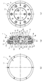
- FIG. 1 is a longitudinal sectional view of a rotary actuator to which the present invention is applied, an end view on a motor side, and an end view on a speed reducer side.
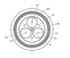
- FIG. 2 is a schematic cross-sectional view of the rotary actuator when cut along line II-II in FIG. 1.
- FIG. 1A is a longitudinal sectional view of the rotary actuator according to the present embodiment
- FIG. 1B is an end view on the motor side
- FIG. 1C is an end view on the speed reducer side. is there.
- the rotary actuator 1 includes a motor 2 and a speed reducer 3 that are coaxially disposed adjacent to each other in the direction of the central axis 1a. Further, an annular rotation output plate 4 is provided on the opposite side of the speed reducer 3 from the motor 2 in a coaxial manner.
- the motor 2 is of the inner rotor type, and the rotating shaft 5, the motor rotor 6 fixed coaxially to the shaft rear end portion 5b of the rotating shaft 5, and the outer periphery of the motor rotor 6 are concentric with a constant gap.
- the speed reducer 3 is a planetary gear speed reducer, and includes a sun gear 8 formed on the outer peripheral surface of the rotating shaft 5, an annular internal gear 9 surrounding the sun gear 8 in a concentric state, the sun gear 8, and the internal gear. 9 and a planetary gear 10 which is arranged between the two and meshes with both of them.
- the rotation of the rotating shaft 5 that is a motor shaft is decelerated via the speed reducer 3 and is output from the rotation output plate 4.
- FIG. 2 is a schematic cross-sectional view of the rotary actuator 1 taken along line II-II in FIG. The internal structure of the rotary actuator 1 will be described in detail with reference to FIGS.
- the rotary actuator 1 includes a first fixed disk 11 that is a first fixing member and a second fixed disk 12 that is a second fixing member.
- the first fixed disk 11 includes a disk-shaped partition plate portion 11 a that partitions between the motor 2 and the speed reducer 3.
- a cylindrical portion 11b that functions as a stator yoke that protrudes on the opposite side of the speed reducer 3 along the direction of the central axis 1a is formed on the outer peripheral edge of the partition plate portion 11a.
- a circular central through hole 11c is formed in the central portion of the partition plate portion 11a.
- the partition plate portion 11a is formed with a columnar protrusion 11d for a spacer that protrudes toward the second fixed disk 12 at equal angular intervals with the central axis 1a as a center.
- the second fixed disk 12 is a disk having a smaller diameter than that of the first fixed disk 11, and a circular recess 12 a that is open on the second fixed disk 12 side is formed at the center of the second fixed disk 12. .
- the second fixed disk 12 is superposed on the front end surfaces of the three cylindrical protrusions 11d of the first fixed disk 11 by three fastening bolts 13 mounted from the outer end surface 12b side.
- the first fixed disk 11 is fastened and fixed.
- a gap having a constant width is formed between the first and second fixed disks 11 and 12 by the cylindrical protrusion 11d.
- a rotating shaft 5 having a center axis 1a as a center of rotation is passed through the central portions of the first and second fixed disks 11 and 12 fastened and fixed at regular intervals.
- the rotating shaft 5 passes through the central through hole 11 c of the first fixed disk 11, and the shaft tip 5 a extends into the recess 12 a of the second fixed disk 12.
- the shaft rear end portion 5b side of the rotating shaft 5 protrudes from the center through hole 11c to the opposite side to the second fixed disk 12.
- a first rolling bearing 14 is mounted between the outer peripheral surface of the shaft rear end 5 b of the rotary shaft 5 and the circular inner peripheral surface of the central through hole 11 c of the first fixed disc 11.
- a second rolling bearing 15 is mounted between the outer peripheral surface of the shaft tip 5 a of the rotating shaft 5 and the circular inner peripheral surface of the recess 12 a of the second fixed disk 12.
- the shaft rear end 5b of the rotary shaft 5 protrudes from the center through hole 11c of the first fixed disk 11 by a predetermined amount in the direction opposite to the second fixed disk 12.
- a motor rotor 6 is coaxially fixed to the shaft rear end portion 5b.
- the motor rotor 6 includes a disk-shaped rotor yoke 6a and a rotor magnet 6b fixed to the circular outer peripheral surface of the rotor yoke 6a.
- a cylindrical boss 6c is formed at the center of the rotor yoke 6a.
- a shaft rear end portion 5b of the rotary shaft 5 is press-fitted and fixed in a circular through hole of the boss 6c.
- the first rolling bearing 14 is mounted on the outer peripheral surface of the boss 6c, and the shaft rear end portion 5b of the rotary shaft 5 is rotatably supported via the boss 6c.
- the motor stator 7 is arranged so as to surround the circular outer peripheral surface of the rotor magnet 6b from the outside in the radial direction with a certain gap.
- the motor stator 7 includes a cylindrical portion 11b (stator yoke) formed on the first fixed disk 11, a plurality of salient poles 7a projecting radially inward from the cylindrical portion 11b at a constant angular interval, and each salient pole. And a drive coil 7b for each phase wound around 7a.
- a disk-shaped motor end cover 16 is fixed to the annular end surface of the cylindrical portion 11b.
- the motor rotor 6 and the motor stator 7 are located in a space surrounded by the first fixed disk 11 and the motor end cover 16.
- the sun gear 8 of the speed reducer 3 is formed on the outer peripheral surface of the shaft portion of the rotating shaft 5 located between the first and second fixed disks 11 and 12.
- Three planetary shafts 17 are spanned between the first and second fixed disks 11 and 12 in a direction parallel to the central axis 1a so as to surround the sun gear 8 concentrically.
- the planetary shaft 17 is disposed so as to be positioned between the cylindrical protrusions 11d in the circumferential direction.
- a planetary gear 10 is rotatably supported on each planetary shaft 17.
- An annular internal gear 9 is disposed outside the planetary gear 10 in the radial direction.
- the internal gear 9 is coaxially fixed to an annular rotation output plate 4 that is arranged adjacent to the opposite side of the first fixed disc 11.
- the rotation output plate 4 is arranged in a state of surrounding the second fixed disc 12 from the outer peripheral side.
- a third rolling bearing 18 is mounted between the circular outer peripheral surface of the second fixed disk 12 and the circular inner peripheral surface of the rotary output plate 4.
- the rotation output plate 4 is supported by the second fixed disk 12 in a freely rotatable state via the third rolling bearing 18.
- a sliding ring 19 is mounted between the rotation output plate 4 and the first fixed disk 11.
- the rotation output plate 4 is supported by the first fixed disk 11 from the direction of the central axis 1a via the sliding ring 19. Further, the sliding ring 19 seals the gap between the rotation output plate 4 and the first fixed disk 11 and prevents the grease from flowing out from the speed reducer 3.
- annular end surface 4 a facing the first fixed disk 11 is formed on the outer peripheral edge of the rotation output plate 4. From the outer peripheral edge of the annular end surface 4a, a cylindrical protrusion 4b is formed that protrudes toward the first fixed disk 11 side. On the first fixed disc 11 side, an annular projecting surface 11e that projects toward the annular end surface 4a is formed.
- a sliding ring 19 having a rectangular cross section is mounted inside the cylindrical projection 4b.
- a minute gap is formed between the annular projecting surface 11e and the cylindrical projection 4b, and a gap between the inner annular projecting surface 11e and the annular end surface 4a is sealed by the sliding ring 19. .
- the sliding ring 19 is fixed to the rotation output plate 4 side, for example, and slides along the annular projecting surface 11e of the first fixed disc 11 as the rotation output plate 4 rotates. Therefore, it is desirable that the sliding ring 19 is made of a material having a low coefficient of friction so that the sliding resistance between the first fixed disk 11 and the annular projecting surface 11e is as small as possible. In addition, it is desirable to form a material with little sliding wear and high wear resistance. Resins or ceramics having such a low coefficient of friction and low wear can be used.
- the motor 2 is rotationally driven to rotate the rotary shaft 5 at high speed.
- the high-speed rotation of the rotating shaft 5 is decelerated by the speed reducer 3, and the internal gear 9 that is the output element rotates at a reduced speed. Accordingly, the reduced speed rotation is output from the rotation output plate 4 fixed to the internal gear 9 to the load side (not shown).
- a planetary gear reducer is used as the reducer 3.
- a cyclo speed reducer (registered trademark), an RV speed reducer, or the like can be used.
Landscapes
- Engineering & Computer Science (AREA)
- General Engineering & Computer Science (AREA)
- Power Engineering (AREA)
- Mechanical Engineering (AREA)
- Connection Of Motors, Electrical Generators, Mechanical Devices, And The Like (AREA)
- Retarders (AREA)
Abstract
Description
中心軸線の方向に所定の間隔を開けた状態で相互に固定された第1固定部材および第2固定部材と、
前記第1、第2固定部材の間に形成された空間と、
前記第1固定部材を前記中心軸線の方向に貫通し、前記第2固定部材まで軸先端部が延びる回転軸と、
前記第1固定部材と前記回転軸の間に装着され、前記回転軸を前記第1固定部材に対して回転自在に支持する第1軸受けと、
前記第2固定部材と前記回転軸の軸先端部の間に装着され、前記回転軸を前記第2固定部材に対して回転自在に支持する第2軸受けと、
前記回転軸における前記第1固定部材から前記第2固定部材とは反対側に突出する軸後端部に固定したモーターローターと、
前記第1固定部材における前記第2固定部材とは反対側の部位に固定され、前記モーターローターの外周を一定のギャップで取り囲むモーターステーターと、
前記第2固定部材の外周を取り囲む回転出力部材と、
前記第2固定部材と前記回転出力部材の間に装着され、前記回転出力部材を前記第2固定部材に対して回転自在に支持する第3軸受けと、
前記第1固定部材および前記第2固定部材の間に組み込まれ、前記回転軸の回転を減速して前記回転出力部材に伝達する減速機構と、
を有していることを特徴としている。
前記回転軸における前記第1、第2固定部材の間に位置する軸部分の外周面に形成した太陽歯車と、
前記第1、第2固定部材の間において、これらの間に架け渡した遊星軸に回転自在に支持され、前記太陽歯車にかみ合っている遊星歯車と、
前記回転出力部材と前記第1固定部材の間に位置し、前記回転出力部材に固定され、前記遊星歯車にかみ合っている内歯歯車と、
を有している。
Claims (5)
- 中心軸線の方向に所定の間隔を開けて相互に固定された第1固定部材および第2固定部材と、
前記第1固定部材を前記中心軸線の方向に貫通し、前記第2固定部材まで軸先端部が延びる回転軸と、
前記第1固定部材と前記回転軸の間に装着され、前記回転軸を前記第1固定部材に対して回転自在に支持する第1軸受けと、
前記第2固定部材と前記回転軸の軸先端部の間に装着され、前記回転軸を前記第2固定部材に対して回転自在に支持する第2軸受けと、
前記回転軸における前記第1固定部材から前記第2固定部材とは反対側に突出する軸後端部に固定したモーターローターと、
前記第1固定部材における前記第2固定部材とは反対側の部位に固定され、前記モーターローターの外周を一定のギャップで取り囲むモーターステーターと、
前記第2固定部材の外周を取り囲む回転出力部材と、
前記第2固定部材と前記回転出力部材の間に装着され、前記回転出力部材を前記第2固定部材に対して回転自在に支持する第3軸受けと、
前記第1固定部材および前記第2固定部材の間に組み込まれ、前記回転軸の回転を減速して前記回転出力部材に伝達する減速機構と、
を有している回転アクチュエータ。 - 前記減速機構は、
前記回転軸における前記第1、第2固定部材の間に位置する軸部分の外周面に形成した太陽歯車と、
前記第1、第2固定部材の間において、これらの間に架け渡した遊星軸に回転自在に支持され、前記太陽歯車にかみ合っている遊星歯車と、
前記回転出力部材と前記第1固定部材の間に位置し、前記回転出力部材に固定され、前記遊星歯車にかみ合っている内歯歯車と、
を有している請求項1に記載の回転アクチュエータ。 - 前記回転出力部材と前記第1固定部材の間に装着され、前記回転出力部材を、前記第1固定部材に対して、前記中心軸線の方向から回転可能に支持するすべり軸受けを有している、
請求項2に記載の回転アクチュエータ。 - 前記すべり軸受けは、前記内歯歯車を取り囲む状態で、前記回転出力部材と前記第1固定部材の間の隙間に摺動可能に装着され、当該隙間をシールしている摺動リングである、
請求項3に記載の回転アクチュエータ。 - 前記第1固定部材の外周縁部分において、前記第2固定部材とは反対側に突出した円筒部と、
前記円筒部の先端開口を封鎖するエンドカバーと、
を有しており、
前記第1固定部材と前記エンドカバーとで囲まれた空間内に前記モーターローターおよび前記モーターステーターが位置している、
請求項1、2、3または4に記載の回転アクチュエータ。
Priority Applications (7)
| Application Number | Priority Date | Filing Date | Title |
|---|---|---|---|
| JP2016524959A JP6207735B2 (ja) | 2014-06-02 | 2014-06-02 | 回転アクチュエータ |
| EP14894161.0A EP3151392B1 (en) | 2014-06-02 | 2014-06-02 | Rotation actuator |
| US15/315,629 US9882450B2 (en) | 2014-06-02 | 2014-06-02 | Rotation actuator |
| CN201480078726.5A CN106416012B (zh) | 2014-06-02 | 2014-06-02 | 旋转致动器 |
| PCT/JP2014/064606 WO2015186172A1 (ja) | 2014-06-02 | 2014-06-02 | 回転アクチュエータ |
| KR1020167032075A KR101838924B1 (ko) | 2014-06-02 | 2014-06-02 | 회전 엑추에이터 |
| TW104117651A TWI678866B (zh) | 2014-06-02 | 2015-06-01 | 旋轉致動器 |
Applications Claiming Priority (1)
| Application Number | Priority Date | Filing Date | Title |
|---|---|---|---|
| PCT/JP2014/064606 WO2015186172A1 (ja) | 2014-06-02 | 2014-06-02 | 回転アクチュエータ |
Publications (1)
| Publication Number | Publication Date |
|---|---|
| WO2015186172A1 true WO2015186172A1 (ja) | 2015-12-10 |
Family
ID=54766276
Family Applications (1)
| Application Number | Title | Priority Date | Filing Date |
|---|---|---|---|
| PCT/JP2014/064606 Ceased WO2015186172A1 (ja) | 2014-06-02 | 2014-06-02 | 回転アクチュエータ |
Country Status (7)
| Country | Link |
|---|---|
| US (1) | US9882450B2 (ja) |
| EP (1) | EP3151392B1 (ja) |
| JP (1) | JP6207735B2 (ja) |
| KR (1) | KR101838924B1 (ja) |
| CN (1) | CN106416012B (ja) |
| TW (1) | TWI678866B (ja) |
| WO (1) | WO2015186172A1 (ja) |
Cited By (1)
| Publication number | Priority date | Publication date | Assignee | Title |
|---|---|---|---|---|
| JP2024122669A (ja) * | 2023-02-28 | 2024-09-09 | パナソニックIpマネジメント株式会社 | モータユニット及び移動装置 |
Families Citing this family (5)
| Publication number | Priority date | Publication date | Assignee | Title |
|---|---|---|---|---|
| CN110242707B (zh) * | 2018-03-08 | 2024-07-12 | 纳博特斯克有限公司 | 传动装置 |
| KR20220149139A (ko) * | 2021-04-30 | 2022-11-08 | 주식회사다스 | 스위블 시트용 파워 구동모듈 |
| CN116940688A (zh) | 2021-05-10 | 2023-10-24 | 韩国科学技术院 | 具有改善的风味、营养和色泽的食品及其制备方法 |
| JP7721111B2 (ja) * | 2021-05-14 | 2025-08-12 | 学校法人千葉工業大学 | 減速機 |
| DE102022106369A1 (de) | 2022-03-18 | 2023-09-21 | Schaeffler Technologies AG & Co. KG | Nockenwellenversteller, Drehaktuator und Verfahren zur Betätigung eines Nockenwellenverstellers |
Citations (1)
| Publication number | Priority date | Publication date | Assignee | Title |
|---|---|---|---|---|
| JP2001072358A (ja) * | 1999-07-02 | 2001-03-21 | Teijin Seiki Co Ltd | エレベータ用巻上げ装置 |
Family Cites Families (11)
| Publication number | Priority date | Publication date | Assignee | Title |
|---|---|---|---|---|
| JPS5936764Y2 (ja) * | 1980-10-15 | 1984-10-11 | 帝人製機株式会社 | 減速機 |
| DE4302042C2 (de) * | 1993-01-26 | 2000-06-08 | Hs Tech & Design | Elektromotor |
| DE59901957D1 (de) * | 1998-08-15 | 2002-08-08 | Krupp Presta Ag Eschen | Elektrisch unterstützte lenkhilfe mit kompaktem planetengetriebe |
| EP1233500A1 (en) * | 2001-02-16 | 2002-08-21 | Chun-Pu Hsu | Drum-type motor with inner gear |
| JP2002276742A (ja) * | 2001-03-09 | 2002-09-25 | Shunho Kyo | 内歯車が外方旋回するドラム式モータ |
| JP2004129374A (ja) | 2002-10-02 | 2004-04-22 | Shinano Kenshi Co Ltd | 減速機付きモータ |
| US7081062B2 (en) * | 2002-11-25 | 2006-07-25 | Delbert Tesar | Standardized rotary actuator |
| JP2005304996A (ja) | 2004-04-26 | 2005-11-04 | Seiko Instruments Inc | 生体情報監視システム |
| JP5595824B2 (ja) | 2010-08-03 | 2014-09-24 | 日本電産コパル電子株式会社 | 減速機付モータ |
| JP5508197B2 (ja) * | 2010-08-30 | 2014-05-28 | 日本電産シンポ株式会社 | 変速機 |
| JP5137150B1 (ja) | 2012-02-23 | 2013-02-06 | 株式会社ワコム | 手書き情報入力装置及び手書き情報入力装置を備えた携帯電子機器 |
-
2014
- 2014-06-02 US US15/315,629 patent/US9882450B2/en active Active
- 2014-06-02 EP EP14894161.0A patent/EP3151392B1/en active Active
- 2014-06-02 KR KR1020167032075A patent/KR101838924B1/ko active Active
- 2014-06-02 WO PCT/JP2014/064606 patent/WO2015186172A1/ja not_active Ceased
- 2014-06-02 CN CN201480078726.5A patent/CN106416012B/zh active Active
- 2014-06-02 JP JP2016524959A patent/JP6207735B2/ja active Active
-
2015
- 2015-06-01 TW TW104117651A patent/TWI678866B/zh active
Patent Citations (1)
| Publication number | Priority date | Publication date | Assignee | Title |
|---|---|---|---|---|
| JP2001072358A (ja) * | 1999-07-02 | 2001-03-21 | Teijin Seiki Co Ltd | エレベータ用巻上げ装置 |
Cited By (1)
| Publication number | Priority date | Publication date | Assignee | Title |
|---|---|---|---|---|
| JP2024122669A (ja) * | 2023-02-28 | 2024-09-09 | パナソニックIpマネジメント株式会社 | モータユニット及び移動装置 |
Also Published As
| Publication number | Publication date |
|---|---|
| JP6207735B2 (ja) | 2017-10-04 |
| KR101838924B1 (ko) | 2018-04-26 |
| US20170194832A1 (en) | 2017-07-06 |
| EP3151392A4 (en) | 2018-03-28 |
| JPWO2015186172A1 (ja) | 2017-04-20 |
| US9882450B2 (en) | 2018-01-30 |
| KR20160145740A (ko) | 2016-12-20 |
| CN106416012A (zh) | 2017-02-15 |
| EP3151392B1 (en) | 2019-04-03 |
| CN106416012B (zh) | 2019-08-27 |
| EP3151392A1 (en) | 2017-04-05 |
| TW201608801A (zh) | 2016-03-01 |
| TWI678866B (zh) | 2019-12-01 |
Similar Documents
| Publication | Publication Date | Title |
|---|---|---|
| JP6207735B2 (ja) | 回転アクチュエータ | |
| JP5482328B2 (ja) | 電動回転アクチュエータ | |
| CN101931286B (zh) | 减速器内置中空传动装置 | |
| JP2015183763A (ja) | 減速機 | |
| JP2017203546A (ja) | 駆動装置 | |
| JP5645028B2 (ja) | 回転電機 | |
| CN105822726B (zh) | 减速机构和带减速机的驱动装置 | |
| JP2020137211A (ja) | ブレーキ付きモータ、ブレーキ付き駆動装置、およびブレーキ付き車輪駆動装置 | |
| WO2020050242A1 (ja) | 駆動装置 | |
| JP2016100910A (ja) | 回転式アクチュエータ | |
| WO2011145302A1 (ja) | シール用回転出力ユニットおよびシール用モータアセンブリ | |
| JP6176328B2 (ja) | 動力伝達装置 | |
| KR20140095064A (ko) | 구동 장치 | |
| JP2019054593A (ja) | 異物の侵入を抑制する電動機 | |
| JP2017169331A (ja) | 扁平アクチュエータ | |
| JP2012080616A (ja) | 可変磁束モータ | |
| TWI738000B (zh) | 具動力源之減速裝置 | |
| JP6568749B2 (ja) | 遊星ローラ式の動力伝達装置 | |
| JP2014011857A (ja) | アクチュエータ | |
| JP2020043620A (ja) | アクチュエータ | |
| JP2019183901A (ja) | 多段式磁気歯車装置 | |
| JP2019103163A (ja) | ブラシレスモータ | |
| JP2015116111A (ja) | 回転システム | |
| CA3121002A1 (en) | Orbital magnetic gears, and related systems | |
| JP2012247010A (ja) | 遊星歯車機構 |
Legal Events
| Date | Code | Title | Description |
|---|---|---|---|
| 121 | Ep: the epo has been informed by wipo that ep was designated in this application |
Ref document number: 14894161 Country of ref document: EP Kind code of ref document: A1 |
|
| ENP | Entry into the national phase |
Ref document number: 2016524959 Country of ref document: JP Kind code of ref document: A |
|
| ENP | Entry into the national phase |
Ref document number: 20167032075 Country of ref document: KR Kind code of ref document: A |
|
| WWE | Wipo information: entry into national phase |
Ref document number: 15315629 Country of ref document: US |
|
| NENP | Non-entry into the national phase |
Ref country code: DE |
|
| REEP | Request for entry into the european phase |
Ref document number: 2014894161 Country of ref document: EP |
|
| WWE | Wipo information: entry into national phase |
Ref document number: 2014894161 Country of ref document: EP |