WO2015186204A1 - 手鋸 - Google Patents
手鋸 Download PDFInfo
- Publication number
- WO2015186204A1 WO2015186204A1 PCT/JP2014/064815 JP2014064815W WO2015186204A1 WO 2015186204 A1 WO2015186204 A1 WO 2015186204A1 JP 2014064815 W JP2014064815 W JP 2014064815W WO 2015186204 A1 WO2015186204 A1 WO 2015186204A1
- Authority
- WO
- WIPO (PCT)
- Prior art keywords
- teeth
- prismatic
- saw
- tooth
- blade
- Prior art date
- Legal status (The legal status is an assumption and is not a legal conclusion. Google has not performed a legal analysis and makes no representation as to the accuracy of the status listed.)
- Ceased
Links
Images







Classifications
-
- B—PERFORMING OPERATIONS; TRANSPORTING
- B27—WORKING OR PRESERVING WOOD OR SIMILAR MATERIAL; NAILING OR STAPLING MACHINES IN GENERAL
- B27B—SAWS FOR WOOD OR SIMILAR MATERIAL; COMPONENTS OR ACCESSORIES THEREFOR
- B27B33/00—Sawing tools for saw mills, sawing machines, or sawing devices
- B27B33/02—Structural design of saw blades or saw teeth
- B27B33/10—Hand saw blades
-
- B—PERFORMING OPERATIONS; TRANSPORTING
- B27—WORKING OR PRESERVING WOOD OR SIMILAR MATERIAL; NAILING OR STAPLING MACHINES IN GENERAL
- B27B—SAWS FOR WOOD OR SIMILAR MATERIAL; COMPONENTS OR ACCESSORIES THEREFOR
- B27B11/00—Cross-cut reciprocating saws with power drive; Appurtenances therefor
-
- B—PERFORMING OPERATIONS; TRANSPORTING
- B27—WORKING OR PRESERVING WOOD OR SIMILAR MATERIAL; NAILING OR STAPLING MACHINES IN GENERAL
- B27B—SAWS FOR WOOD OR SIMILAR MATERIAL; COMPONENTS OR ACCESSORIES THEREFOR
- B27B21/00—Hand saws without power drive; Equipment for hand sawing, e.g. saw horses
-
- B—PERFORMING OPERATIONS; TRANSPORTING
- B27—WORKING OR PRESERVING WOOD OR SIMILAR MATERIAL; NAILING OR STAPLING MACHINES IN GENERAL
- B27B—SAWS FOR WOOD OR SIMILAR MATERIAL; COMPONENTS OR ACCESSORIES THEREFOR
- B27B21/00—Hand saws without power drive; Equipment for hand sawing, e.g. saw horses
- B27B21/04—Cross-cut saws; Pad saws
Definitions
- the present invention relates to a hand saw.
- the saw has a long history, and hand saws have been used by many people since the beginning.
- the electric saw has been developed relatively recently, and is an electric tool that cuts wood or the like with overwhelming horsepower using electric power. The same applies to chainsaws using engines. So-called power saws with overwhelming power, such as the electric saw, and hand saws that cut only with human power without using such power are the same in that they use cutting teeth. In reality, however, the concepts regarding their configuration and functions are greatly different, and the technical fields are substantially different.
- FIG. 12 shows an example of a hand saw.
- the hand saw has a configuration in which an elongated metal saw blade 2 is attached to the tip of a grip portion 1 generally called a handle, and a plurality of teeth 3 are arranged on a longitudinal side edge of the saw blade 2.
- the hand saw shown in FIGS. 10A and 10B is an example of a so-called vertical saw.
- a vertical saw is a saw suitable for cutting wood along the grain direction.
- a large number of triangular teeth 3 are arranged on the side edge of the saw blade 2 in the longitudinal direction, and the tip of the triangular teeth 3 is used as a cutting edge P for cutting.
- the skirt of each triangular tooth 3 forms a valley V with the skirt of the adjacent triangular tooth 3.
- the hand saw shown in FIGS. 11A and 11B is an example of a so-called horizontal saw.
- a horizontal saw is a saw that is suitable for cutting a tree in a crossing direction.
- This horizontal saw saw comprises sharp vertical blades 3a and 3b called "postcards" at a pair of front and rear inclined portions of the tips of the triangular teeth 3 formed on the side edges of the saw blade 2 in the longitudinal direction.
- the longitudinal blade indicated by reference numeral 3a is in front of the cutting direction D
- the vertical blade indicated by reference numeral 3b is behind the cutting direction D.
- the vertical blades 3a and 3b cut into a tree like a knife and cut the grain.
- the skirt of each adjacent triangular tooth 3 constitutes a valley V.
- the vicinity of the tip of the triangular tooth 3 is cut obliquely to form a tip cut surface 4 called “upper eye”, and the front and rear edges of the tip cut surface 4 are set to the horizontal blades 4a, 4b.
- the tip cut surface 4 and the horizontal blades 4a and 4b can perform the function of a vertical saw, and when cutting a tree, scoop the wood part corresponding to the thickness of the saw blade 2 like a chisel, Plays a scraping function.
- Patent Document 1 describes a hand in which upper teeth (11a) to (18a) are configured in addition to a configuration in which triangular teeth (11) to (18) are alternately arranged.
- a saw blade is disclosed. This hand saw is a saw similar to the horizontal saw shown in FIG. 9 described above.
- Patent Document 2 discloses a recess formed on the outer surface of the cutting blade (2) for the purpose of eliminating clogging between chips on both sides of the saw and the cutting surface of the tree.
- a saw blade provided with a chip storage portion (7) comprising (10) is disclosed.
- Patent Document 3 discloses that the bases (3B) and (3B) of adjacent teeth (3) and (3) are arc-shaped groove bottoms for the purpose of preventing clogging of chips.
- a saw blade formed in a separated shape via (20) is disclosed.
- the hand saw of the above-mentioned patent document 1 is composed of triangular teeth as in the case of the hand saw shown in FIG. 11, the valley (V) (see FIG. 11) between adjacent triangular teeth is the bottom of the valley. Therefore, it is necessary to make the structure constricted in a V shape. For this reason, there has been a basic problem that chips are clogged in this constricted valley and the sharpness gradually becomes worse as the operation proceeds.
- the saw blade of the above-mentioned patent document 2 it is possible to eliminate clogging between chips on both sides of the saw and the cut surface of the tree. However, the problem that the sharpness gradually deteriorates during operation remains.
- the chip is less likely to be clogged due to the presence of the bottom surface of the arc-shaped groove (20). Clogging is not fully resolved.
- the chamfered angle (7A) and the chamfer angle (7B) of the ragged portions (7A) are made to be considerably acute in order to form a large arc of the arc-shaped groove bottom surface (20).
- the thickness of each tooth (3) becomes thin, resulting in a problem that the strength decreases.
- the sharp edges of the ridges (7A) and (7B) are tight, there is a problem that the area of the upper eye (8) must be very small.
- the triangular tooth of the hand saw is a saw tooth shape that has been followed for a long time. Speaking of the saw tooth, the triangular tooth was common sense.
- the triangular teeth as described above, there is a basic problem that valleys narrowed between the triangular teeth exist and chips are easily clogged.
- the longitudinal pitch of the saw blade at the tip of each tooth tends to be long and sparse. If the triangular teeth are arranged more closely in order to reduce the pitch, the overlapping of the valleys between the triangular teeth increases, the chips are easily clogged, and the sharpness is reduced.
- the present invention solves the above-mentioned problems of the prior art, and by overturning the common sense of a manual saw having a tooth shape that has been followed in the past, such as triangular teeth, the clogging of chips can be dramatically eliminated and the cutting edge can be removed. It is possible to keep the pitch of the tooth dense without making it sparse, and to secure a large area of the inclined cutting surface of the tip of the tooth called the “upper eye”, and thus the sharpness due to clogging of the chips It is an object of the present invention to provide a hand saw that can sufficiently prevent the deterioration of the sharpness and can greatly improve the sharpness itself.
- the hand saw of the present invention is a hand saw formed by arranging a plurality of saw teeth on the side edge in the longitudinal direction of the saw blade, and the saw teeth are configured as prismatic teeth having a prismatic shape.
- each prismatic tooth is configured such that at least the adjacent prismatic teeth have the same rising angle from the edge surface of the longitudinal side edge of the saw blade, so that the spacing between adjacent prismatic teeth is the same.
- the first feature is that the gap is constant in the tooth rising direction.
- the prismatic teeth are triangular prismatic or trapezoidal prismatic teeth, and at least one side surface of the prismatic teeth is on one side of the front and back surfaces of the saw blade.
- the prismatic teeth are arranged by changing the orientation of the prismatic teeth alternately so that the one surface is alternately positioned with respect to the front and back sides of the saw blade.
- a side blade belonging to the one side surface of the columnar tooth constitutes a vertical blade
- the tip of the prismatic tooth constitutes a tip inclined cut surface formed by obliquely cutting the prism and at the tip inclined cut surface.
- a second feature is that a horizontal blade is formed on an edge that does not belong to the same surface among the edges that belong to it.
- the hand saw of the present invention has triangular prismatic teeth as the prismatic teeth, and each triangular prismatic tooth has two side edges of the three pillars of the pillar.
- Each side of the front and back of the blade is configured as both sides of the one side, and the remaining one side is configured as a side that rises flush with the other side of the saw blade.
- the third feature is that the tooth tip inclined cut surface is formed into an inclined triangle straddling both sides of the saw blade.
- the hand saw of the present invention has a fourth feature that the triangular prismatic teeth are isosceles triangular prismatic teeth.
- the hand saw of the present invention has a trapezoidal columnar tooth as a prismatic tooth, and each of the trapezoidal columnar teeth has two side edges out of the four side edges of the column.
- the trapezoidal columnar teeth have a tip inclined cut surface that is an inclined quadrangle straddling both sides of the saw blade.
- the hand saw of the present invention has a sixth feature that the trapezoidal columnar shape is an isosceles trapezoidal columnar tooth.
- the hand saw of the present invention has a seventh feature that, in addition to any of the first to sixth features, the prismatic teeth are right prismatic teeth or oblique prismatic teeth.
- the hand saw of the present invention includes, in addition to any one of the first to seventh features described above, a difference within ⁇ 10 degrees from the same angle in the rising angle of the prismatic teeth.
- the constant in the rising direction of the gap between them is an eighth feature that includes an expansion within an angle of 20 degrees and a reduction within an angle of 20 degrees.
- the rising angle of each prismatic tooth includes a difference within ⁇ 5 degrees, and the gap between the prismatic teeth is constant in the rising direction.
- the ninth feature is to include enlargement within an angle of 10 degrees and reduction within an angle of 10 degrees.
- the hand saw of the present invention in addition to any one of the above first to ninth features, has both sides on each side of each prismatic tooth having crossing angles within ⁇ 10 degrees from each other or parallel to each other.
- the tenth feature is that it is configured to stand up.
- the hand saw of the present invention is configured such that both side sides of each side surface of each prismatic tooth rise with a cross angle within ⁇ 5 degrees from each other or parallel to each other. Is the eleventh feature.
- the saw teeth arranged in the saw blade are prismatic teeth, and each prismatic tooth has at least the adjacent prismatic teeth of the longitudinal side edge of the saw blade.
- the gap between the adjacent prismatic teeth is made constant in the rising direction of the teeth.
- the shape of the saw blade is a prismatic shape
- the dimension from the tooth bottom to the tooth tip does not change compared to a conventional triangular tooth having a wide tooth bottom and a narrow tooth tip. Therefore, compared with the conventional triangular tooth, it is possible to arrange the teeth more closely in the prismatic tooth.
- gear can be enlarged more with a prismatic tooth. As a result, it is possible to increase the arrangement density of the cutting blades formed on the saw blades, increase the blade size of the cutting blades themselves, and greatly improve the sharpness.
- the prismatic teeth are triangular columnar teeth or trapezoidal columnar teeth.
- the triangular columnar teeth or trapezoidal columnar teeth are arranged such that one side surface of the prismatic teeth is alternately arranged on the left and right sides of the front and back sides of the saw blade, and a vertical blade is provided on the one side surface alternately arranged on the left and right sides. Composed. By the left and right alternating vertical blades, a pair of left and right cut grooves are cut into the object to be cut. Further, the tip of the triangular columnar tooth or the trapezoidal columnar tooth is a tip inclined cut surface formed by obliquely cutting a prism.
- a side blade is comprised in the edge which does not belong to the one side surface among the edges of the front-end
- the object to be cut is sliced and scraped off in an oblique horizontal direction so as to cut with a chisel. Therefore, according to the hand saw of the second aspect, in addition to the function and effect of the configuration of the first aspect, by using a triangular columnar tooth or a trapezoidal columnar tooth, a combination of a vertical blade and a horizontal blade, The object to be cut can be cut well, and it is possible to provide a very sharp hand saw that does not clog the chips between the teeth.
- the prismatic teeth are triangular prismatic teeth.
- the triangular columnar teeth have two sides that are flush with one side of the front and back sides of the saw blade, and the remaining one side is flush with the other side of the saw blade.
- the tip inclined cut surface of the triangular prismatic teeth becomes a large inclined triangle straddling the front and back sides of the saw blade, and the horizontal blade formed on the edge of the triangle of the tip inclined cut surface has a length straddling the front and back sides of the saw blade. Of the blade.
- the sliced object will be efficiently sliced in a slanting horizontal direction with a large horizontal blade across the front and back of the saw blade, and a very sharp hand saw can be provided in which there is no uncut residue within the thickness of the saw blade. .
- the triangular columnar teeth are isosceles triangular columnar teeth.
- the opposing side surfaces can be arranged in parallel. Therefore, the gap between adjacent triangular columnar teeth can be constant not only in the rising direction of the sawtooth, but also in the direction perpendicular to the rising direction. Thereby, stable cutting work and sharpness can be ensured.
- the prismatic teeth are trapezoidal columnar teeth.
- the trapezoidal columnar teeth have two opposite side surfaces that are flush with the front and back sides of the saw blade, and the remaining two opposite side surfaces each cross the front and back side surfaces of the saw blade.
- the tip inclined cut surface of the triangular columnar tooth becomes a large inclined trapezoid that spans the front and back sides of the saw blade, and therefore the horizontal blade that is configured on the edge of the trapezoid of the tip inclined cut surface has a long diameter straddling the side surfaces of the saw blade. Become a blade.
- the trapezoidal columnar teeth are isosceles trapezoidal columnar teeth. It becomes possible to arrange them in parallel. Therefore, the gap between adjacent trapezoidal columnar teeth can be constant not only in the rising direction of the sawtooth, but also in the direction perpendicular to the rising direction. Thereby, the stable sharpness is securable.
- each prismatic tooth rises straight from the edge surface of the saw blade as a right prism
- each prismatic tooth rises diagonally from the edge surface of the saw blade as an oblique prism
- the rising angle of the adjacent prismatic teeth is the same angle.
- the angle shall include a difference within ⁇ 10 degrees.
- the gap in the rising direction of the teeth between the prismatic teeth is constant, the expansion within 20 degrees and the reduction within 20 degrees. It can be made constant within the allowable range. Even if the gap between the prismatic teeth expands or contracts within 20 degrees as the angle in the rising direction, there is no adverse effect that the chips are clogged into the interdental gap within that range. Does not adversely affect sharpness.
- the rising angle of each prismatic tooth includes the difference within ⁇ 5 degrees. It is said. Based on this, the gap between the prismatic teeth in the rising direction of the teeth is allowed to expand or contract within an allowable range of 10 degrees or less. If the change in the gap between the prismatic teeth is within an allowable range of 10 degrees in the rising direction, the clogging of the chips into the gap between the teeth can be effectively prevented and the sharpness of the saw can be reduced. It can be held sufficiently well.
- each prismatic tooth has both sides rising up in parallel on each side, It is allowed to stand up at an angle of intersection within ⁇ 10 degrees from parallel. Even if the prisms of the prismatic teeth are reduced or expanded in the rising direction within such a range of 10 degrees or less, if they are within that range, the shape characteristics as prismatic teeth can be exhibited. In addition, there is no adverse effect that the chips are stuck in the gaps between the teeth, and the sharpness of the saw is not adversely affected.
- each prismatic tooth rises in parallel on both sides on each side surface or within ⁇ 5 degrees from the parallel. It is preferable to stand up at an angle of intersection.
- the reduction or expansion of the prismatic teeth in the rising direction of the prism is within a range of 5 degrees or less, the feature of the shape as the prismatic teeth can be fully exhibited, and the gap between the teeth of the chips It is possible to prevent clogging to a sufficient extent, and to maintain the sharpness of the saw sufficiently satisfactorily.
- FIG. 1 It is a front view which shows the hand saw which concerns on 1st Embodiment of this invention.
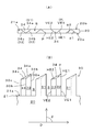
- the details of the hand saw concerning a 1st embodiment of the present invention are shown, (A) is a top view and (B) is a front view.
- the sawtooth of the hand saw concerning a 1st embodiment of the present invention is shown, (A) is a top view and (B) is a perspective view seen from the front direction. It is a figure which shows the dimensional relationship of each part of the sawtooth of the hand saw which concerns on 1st Embodiment of this invention.
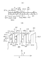
- the detail of the hand saw which concerns on 2nd Embodiment of this invention is shown, (A) is a top view, (B) is a front view. The details of the hand saw concerning a 3rd embodiment of the present invention are shown, (A) is a top view and (B) is a front view.
- the detail of the hand saw which concerns on 4th Embodiment of this invention is shown, (A) is a top view of a triangular columnar tooth, (B) is a top view of a trapezoid columnar tooth.
- the details of the hand saw concerning a 5th embodiment of the present invention are shown, (A) is a top view of a triangular columnar tooth, and (B) is a top view of a trapezoidal columnar tooth.
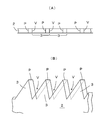
- FIG. 1 An example of the conventional vertical saw is shown, (A) is a plan view, (B) is a perspective view seen from the front direction.
- An example of the conventional horizontal saw is shown, (A) is a plan view and (B) is a front view. It is a figure which shows an example of the conventional hand saw.
- the hand saw has a grip portion 10, a saw blade 20, and a saw tooth 30. Note that a part of the grip portion 10 is omitted in the drawing.
- the hand saw is shown as a foldable hand saw that can fold the saw blade 20 into the grip portion 10, it does not necessarily have to be foldable, and any hand saw can be used.
- the hand saw is a so-called single-blade saw, and saw teeth 30 are arranged on the longitudinal side edge 21 on one side of the saw blade 20.
- a double-edged saw in which saw blades 30 are arranged on the longitudinal side edges 21 on both sides of the saw blade 20 may be used.
- the hand saw shown in FIG. 1 is comprised as a drawing saw, it may be a push saw.
- the saw tooth is configured as a prismatic tooth 30 in the first embodiment.
- the prismatic teeth 30 are configured to rise from the edge surface 21 a of the longitudinal side edge 21 of the saw blade 20.
- Each prismatic tooth 30 has a constant rising angle ⁇ so that it rises in the same direction from the edge surface 21a.
- the rising angle ⁇ of the prismatic teeth 30 shown in the first embodiment is 90 degrees and is vertical. As long as the rising angle ⁇ of each prismatic tooth is constant, it may not be vertical but may be inclined obliquely. By making the rising angle ⁇ of each prismatic tooth 30 constant, the gap S between the adjacent prismatic teeth 30 becomes constant in the rising direction of the prismatic teeth.
- the gap S between the prismatic teeth 30 and 30 is constant in the rising direction of the teeth, and the gap between the teeth extends from the tip of the tooth to the bottom of the tooth.
- the disadvantage of constricting towards the part is eliminated.
- the constant rise angle ⁇ is not limited to a constant value in a strict sense.
- the same angle at the rising angle ⁇ does not need to be the same angle in a strict sense.
- the constant in the gap S between the adjacent prismatic teeth 30 does not need to be constant in a strict sense. It is a concept including some increase and decrease allowed based on the object, function, and effect of the invention. This point will be described later.
- the prismatic teeth 30 of the first embodiment are triangular prismatic teeth made of triangular prisms.
- the triangular columnar tooth 30 includes three side edges 30 a, 30 b, 30 c that rise from the edge face 21 a of the longitudinal side edge 21 of the saw blade 20, and three side faces 31, 32, 33.
- the tip of the triangular columnar tooth 30 is provided with a tip inclined cut surface 34 formed by cutting the triangular column obliquely.
- the tip inclined cut surface 34 includes three edges 34a, 34b, and 34c.
- the edge side 34 a corresponds to the upper side of the side surface 31
- the edge side 34 b corresponds to the upper side of the side surface 32
- the edge side 34 c corresponds to the upper side of the side side 33.
- the triangular columnar tooth 30 is configured such that one side surface thereof is a surface-one side surface 31 that rises flush with any one side surface 20a, 20b of the front side surface 20a and the back side surface 20b of the saw blade 20. Yes. Each triangular columnar tooth 30 is alternately changed in the direction of the triangular columnar teeth 30 so that the flush side surface 31 is alternately flush with the front side surface 20a and the back side surface 20b of the saw blade 20. It is configured to be arranged. A corner (side 30b) of each triangular columnar tooth 30 facing the flush side surface 31 is located at an intermediate position between both sides 30a and 30c of the flush side surface 31 in the longitudinal direction of the saw blade 20. Is done.
- each triangular columnar tooth 30 is such that each of the crossing angles ⁇ 1 and ⁇ 2 of the side surfaces 32 and 33 adjacent to the flush side surface 31 is less than 90 degrees.
- the crossing angles ⁇ 1 and ⁇ 2 are both the same angle of less than 90 degrees, and the triangle is configured as an isosceles triangular prismatic tooth composed of symmetrical isosceles triangles. Yes.
- the isosceles triangular prismatic teeth 30 By forming the isosceles triangular prismatic teeth 30 into the isosceles triangular prismatic teeth 30, when the isosceles triangular prismatic teeth 30 are alternately arranged on the side edges 21 in the longitudinal direction of the saw blade 20, the adjacent isosceles are adjacent to each other.
- the opposing side surface 32 and side surface 33 of the triangular columnar teeth 30, 30 are parallel in a plan view. That is, the gap S between the adjacent isosceles triangular columnar teeth 30 can be made constant in a plan view (also in a direction perpendicular to the rising direction).
- Each triangular prism-like tooth 30 has a front vertical blade VE1 formed on a long side 30a located in front of the cutting direction D among the sides 30a and 30c belonging to the same side surface 31, and rearward in the cutting direction D.
- the rear vertical blade VE2 is formed on the short side 30c.
- the cutting direction D is a direction in which a saw is drawn in the case of a drawing saw. In the case of a push saw, it is the direction in which the saw is pushed.
- the blade angle of the front vertical blade VE1 (intersection angle ⁇ 1 between the side surface 31 and the side surface 32) and the blade angle of the rear vertical blade VE2 (intersection angle ⁇ 2 between the side surface 31 and the side surface 33) are both acute angles of less than 90 degrees.
- the front vertical blade VE1 is a main vertical blade that cuts a V-shaped groove into the object to be cut when the saw blade 20 moves in the cutting direction D.
- the rear vertical blade VE2 is a blade that can make a V-shaped cut in the object to be cut when the saw blade 20 returns in the direction opposite to the cutting direction D, but follows the front vertical blade VE1. It is a vertical blade.
- Each triangular columnar tooth 30 is an edge 34b that does not belong to the flush side surface 31 and is located in front of the cutting direction D among the three edges 34a, 34b, 34c belonging to the tip inclined cut surface 34 formed at the tip.
- a front horizontal blade HE1 is formed, and a rear horizontal blade HE2 is formed on an edge 34c that does not belong to the flush side surface 31 and is located rearward in the cutting direction D.
- the blade angle of the front horizontal blade HE1 is an intersection angle between the tip inclined cut surface 34 and the side surface 32 constituting the blade surface of the front vertical blade VE1. This crossing angle is less than 90 degrees.
- the front horizontal blade HE1 and the front vertical blade VE1 merge at the cutting edge P of the triangular columnar tooth 30.
- the front horizontal blade HE1 slices and cuts the surface of the object to be cut in an oblique horizontal direction so as to cut the surface of the object to be cut with a chisel.
- the rear horizontal blade HE2 is useful for discharging chips from the cut groove of the object to be cut when the saw blade 20 moves in the direction opposite to the cutting direction D.
- the tip inclined cut surface 34 is configured to be cut obliquely downward at a constant inclination angle with the cutting edge P as a vertex.
- the cutting edge P (tip of 30a) is not set as the apex, but the tip of the side 30b is set as the apex, and obliquely downward from the tip of the side 30b, which is the apex, at a certain inclination angle.
- an inclined cut surface (hereinafter, referred to as a different kind of tip inclined cut surface). More specifically, this different type of inclined cut surface is more inclined from the tip of the side 30b to the edge 34c than to the slope of the edge 34b from the tip of the side 30b to the cutting edge P (tip of 30a). It is configured to be steep.
- the triangular columnar teeth having different types of inclined cutting surfaces at the front end (the same applies to the trapezoidal columnar teeth described later), the above-mentioned front end is excellent in the function of discharging chips from the cut grooves of the object to be cut.
- the triangular prismatic teeth 30 having the inclined cut surfaces 34 can be arranged at various locations.
- each triangular columnar tooth 30 is columnar, and the dimension of the tooth 30 does not change from the hem of the tooth toward the tip.
- each triangular columnar tooth 30 stands up in the same direction with its rising angle ⁇ being constant, such as rising up vertically in the same direction. Accordingly, the gap S between the adjacent triangular columnar teeth 30 is constant in the rising direction of the triangular columnar teeth 30. That is, the gap S between the teeth 30 is ensured without a sufficient gap being narrowed down to the bottom of the gap S.
- the triangular columnar tooth 30 has a columnar shape, and the size does not decrease from the skirt portion to the tip portion of the tooth. Therefore, compared with the conventional triangular tooth, the tip inclined cut surface 34 formed at the tip of the tooth 30 has a sufficiently large area, and the blade span of the horizontal blades HE1 and HE2 formed on the tip inclined cut surface 34 is sufficiently long. can do. Thereby, the width
- the area of the tip inclined cut surface 34 is larger in the case of the triangular columnar tooth 30 and the dimension between each tooth hem than in the case of the conventional triangular tooth. Can also be increased.
- the large dimension between each tooth hem means that the chips are not easily clogged.
- the large area of the tip inclined cut surface 34 means that the sharpness of the slice cut by the horizontal blades HE1 and HE2 is large.
- the triangular prismatic teeth 30 can arrange more teeth at a smaller pitch than the conventional triangular teeth, and the sharpness of the saw itself is further improved. Can be made.
- the triangular columnar teeth 30 are isosceles triangular teeth, the opposing side surfaces 32 and 33 of each adjacent triangular columnar tooth 30 are parallel to each other in a plan view, so that the dimension of the gap S is perpendicular to the rising direction. It will be constant and will not change. Accordingly, the uneven distribution of chips in the gap S is reduced by that amount, and a more stable cutting operation and sharpness can be expected.
- the triangular prism-like tooth 30 is a surface that rises flush with one side surface 20a (20b) of the front and back of the saw blade 20 at two side portions 30a, 30c of the three side sides 30a, 30b, 30c. Both side sides of one side 31 are formed, and the remaining one side 30b is configured as a side that rises flush with the remaining one side 20b (20a) of the saw blade 20. Accordingly, each tip inclined cut surface 34 is configured to be an inclined triangle straddling the front and back side surfaces 20a, 20b of the saw blade 20.
- each tip inclined cut surface 34 By forming each tip inclined cut surface 34 into an inclined triangle straddling the front and back side surfaces 20a, 20b of the saw blade 20, the side blades HE1, HE2 formed on each tip inclined cut surface 34 are the front and back sides of the saw blade 20.
- the blade span (blade length) completely crosses the thickness between 20a and 20b.
- the horizontal blades HE1 and HE2 formed on the respective inclined cutting surfaces 34 completely traverse the thickness of the saw blade 20, so that the horizontal blades HE1 and HE2 are cut in the thickness direction of the saw blade 20 when the workpiece is cut.
- the object to be cut can be cut over the entire area.
- the horizontal blades HE1 and HE2 have a length that ends with less than a majority in the thickness direction of the saw blade 20, the horizontal blades HE1 and HE2 cannot cut the object to be cut in the entire thickness direction of the saw blade. There is a tendency that a part of the cut body remains only in frictional contact. This is often the case with conventional triangular teeth, and the sharpness tends to deteriorate, and the cutting efficiency tends to deteriorate.
- the direction of the triangular columnar teeth 30 is alternately changed in the opposite direction, so that each horizontal blade HE1 and HE2 is separated from the adjacent horizontal blade 2
- the object to be cut can be cut without being left uncut across the entire thickness direction of the saw blade 20 in pairs.
- the area of the tip inclined cut surface 34 can be easily increased, and the lengths of the horizontal blades HE1 and HE2 can be easily set to the length in the thickness direction of the saw blade 20.
- tooth strength it is more preferable in terms of tooth strength.
- prismatic teeth are configured as trapezoidal columnar teeth 40.
- the bottom face shape of the triangular prismatic teeth 30 according to the first embodiment is a triangle. This triangle becomes a trapezoid by cutting one corner facing the bottom surface.
- such trapezoidal columnar teeth 40 are arranged on the edge surface 21 a of the longitudinal side edge 21 of the saw blade 20.
- Each of the trapezoidal columnar teeth 40 is a surface that rises flush with one side surface 20a (20b) of the front and back of the saw blade 20 with two side sides 40a, 40c of the four side sides 40a, 40b, 40c, 40d of the column.
- the two side surfaces 40b and 40d are configured as both sides of the second side surface 45 that rises flush with the other side surface 20b (20a) of the front and back of the saw blade 20.
- the second flat side surface 45 has a smaller area than the flat side surface 41.
- Each trapezoidal tooth 40 has two side surfaces 42 and 43 in addition to the one surface 41 and the second surface 45.
- Each trapezoidal columnar tooth 40 is configured to rise in the same direction from the edge surface 21 a of the longitudinal side edge 21 of the saw blade 20, that is, so that the rising angle ⁇ is constant.
- the rising angle ⁇ of the trapezoidal columnar tooth 40 shown in the second embodiment is 90 degrees and is vertical. As long as the rising angle ⁇ of each trapezoidal columnar tooth is constant, it may not be vertical but may be inclined obliquely.
- the tip of the trapezoidal columnar tooth 40 is provided with a tip inclined cut surface 44 formed by obliquely cutting the trapezoidal column.
- the tip inclined cut surface 44 includes four edges 44a, 44b, 44c, and 44d.
- the edge 44 a corresponds to the upper side of the flush side 41
- the edge 44 b corresponds to the upper side of the side 42
- the edge 44 c corresponds to the upper side of the side 43
- the edge 44 d corresponds to the second side 45.
- the trapezoidal columnar teeth 40 are arranged by alternately changing the direction of the teeth so that the flush side surface 41 is alternately flush with the front side surface 20a and the back side surface 20b of the saw blade 20. It is configured to be.
- Each of the trapezoidal columnar teeth 40 has an intersection angle ⁇ 1, ⁇ 2 between the side surface 41 and the side surfaces 42, 43 adjacent to each other is less than 90 degrees.
- the trapezoid is configured as an isosceles trapezoidal columnar tooth 40 composed of a symmetrical isosceles trapezoid.
- the isosceles trapezoidal columnar teeth 40 when the isosceles trapezoidal columnar teeth 40 are alternately arranged on the side edges 21 of the saw blade 20 in the left-right direction, the adjacent isosceles trapezoidal columnar teeth 40 are adjacent to each other. , 40 are parallel to each other in the plan view. That is, the gap S between the adjacent isosceles trapezoidal columnar teeth 40 can be made constant in a plan view (even in a direction perpendicular to the rising direction).
- Each of the trapezoidal columnar teeth 40 has a front vertical blade VE1 formed on a long side 40a located in front of the cutting direction D among the sides 40a and 40c belonging to the flush side 41, and the rear of the cutting direction D.
- the rear vertical blade VE2 is formed on the short side 40c.
- the blade angle of the front vertical blade VE1 (intersection angle ⁇ 1 between the side surface 41 and the side surface 42) and the blade angle of the rear vertical blade (intersection angle ⁇ 2 between the side surface 41 and the side surface 43) are both acute angles of less than 90 degrees. An acute angle of 45 degrees or less is preferable.
- the rear vertical blade VE2 is a blade that can make a V-shaped cut in the object to be cut when the saw blade 20 returns in the direction opposite to the cutting direction D, but follows the front vertical blade VE1. It is a vertical blade.
- a front horizontal blade HE1 is formed on the edge 44b of the tip inclined cut surface 44 formed at the tip of each trapezoidal columnar tooth 40, and a rear horizontal blade HE2 is formed on the edge 44c.
- the front horizontal blade HE1 is in front of the cutting direction D and is formed so as to cross the saw blade 20 obliquely in the thickness direction.
- the rear horizontal blade HE1 is located behind the cutting direction D.
- the blade angle of the front horizontal blade HE1 is an intersection angle between the tip inclined cut surface 44 and the side surface 42 constituting the blade surface of the front vertical blade VE1. This crossing angle is less than 90 degrees.
- the front horizontal blade HE1 and the front vertical blade VE1 merge at the cutting edge P of the trapezoidal columnar tooth 40.
- the chips scraped off by the trapezoidal columnar teeth 40 once remain in the gaps S in front of the trapezoidal columnar teeth 40.
- the gap S of each tooth 40 is ensured by the above-described configuration without causing a sufficient gap to reach the bottom of the gap S. Therefore, the sharpness of the saw does not deteriorate due to the chips clogging into the bottom of the gap S over time, and a good sharpness can be maintained.
- the strength of the tooth itself can be increased as compared with the triangular columnar tooth 30, but the width of the tooth can be easily taken in the longitudinal direction of the saw blade 20.
- Other effects of the hand saw using the trapezoidal columnar teeth 40 are the same as those described above for the hand saw using the triangular columnar teeth 30.
- the columnar teeth 30 and 40 are the right-angled columnar teeth, and the triangular columnar teeth 30 and the trapezoidal columnar teeth 40 are the longitudinal side edges 21 of the saw blade 20.
- a hand saw rising from the edge surface 21a with a vertical rising angle ⁇ is shown.
- a hand saw in which the oblique columnar teeth 50 rise with a rising angle ⁇ inclined from the edge surface 21a of the longitudinal side edge 21 of the saw blade 20 is shown.
- the rising angle ⁇ of the oblique columnar teeth 50 is a constant angle slightly tilted from the vertical to the cutting direction D of the hand saw in addition to the vertical of 90 degrees.
- the gap S between the adjacent oblique columnar teeth 50 and 50 can be made constant in the rising direction of the teeth 50. As a result, the gap S does not squeeze toward the hem of the teeth, and a gap S having a sufficient size can be secured.
- the rising angle ⁇ of the oblique columnar teeth 50 is not necessarily limited, but is preferably within ⁇ 30 degrees from the vertical direction (90 degrees).
- Other features of the hand saw of the third embodiment provided with the oblique columnar teeth 50 are the same as those of the hand saw of the first embodiment.
- the side surfaces 31, 32, 33, the tip inclined cut surface 34, the side edges 30a, 30b, 30c, and the side edges 34a, 34b, 34c indicated by the reference numerals of the right triangular prism teeth 30 in the first embodiment are oblique triangular prismatic teeth.
- the clearance S, the vertical blades VE1, VE2, the horizontal blades HE1, HE2, and the vertex P are the same as those in the first embodiment.
- the prismatic teeth are triangular prismatic teeth (see FIG. 8 (A)) and trapezoidal columnar teeth (FIG. 8 (B)). It is the same as the triangular columnar teeth 30 and 50 according to the form and the trapezoidal columnar teeth 40 according to the second embodiment.
- the triangular columnar teeth 60 and 60 see FIG. 8A
- the trapezoidal columnar teeth 70 and 70 are arranged relatively densely. ing.
- the gap S is also configured so that a substantial part thereof is hidden behind the teeth 60 (70).
- the gap S maintains a constant width in the rising direction of the tooth 60 (70), and the gap S does not narrow toward the root of the tooth.
- the prismatic teeth are triangular prismatic teeth (see FIG. 9 (A)) and trapezoidal columnar teeth (FIG. 9 (B)). This is the same as the triangular columnar teeth 30 and 50 according to the third embodiment and the trapezoidal columnar teeth 40 according to the second embodiment.
- the triangular shape of the triangular columnar tooth 80 see FIG. 9A
- the trapezoidal shape of the trapezoidal columnar tooth 90 see FIG.
- the saw It is not a triangle or trapezoid having a size extending from the front side surface 20a of the body 20 to the back side surface 20b.
- the hand saw of the present invention is provided with the function as the prismatic teeth. It can be said that it is a tooth used for the.
- the triangular columnar teeth 80 and the trapezoidal columnar teeth 90 that are not formed in the entire area in the thickness direction of the saw blade 20 have the horizontal blades HE1 and HE2 formed on the tip inclined cut surfaces thereof in the thickness direction of the saw blade 20 as well. Since it is not formed in the entire region, a portion that cannot be cut off by the transverse HE1 and HE2 is generated in the thickness of the saw blade 20. This leads to a reduction in the sharpness of the hand saw itself. Therefore, the triangular and trapezoidal sizes of the triangular columnar teeth 80 and the trapezoidal columnar teeth 90 are at least larger than the half area of the saw blade 20 in the thickness direction, as shown in FIGS. It is good.
- the triangular or trapezoidal size of the triangular columnar teeth 80 and the trapezoidal columnar teeth 90 exceeds the half region in the thickness direction of the saw blade 20, the triangular columnar teeth 80 and the trapezoidal columnar teeth 90 are alternately opposed to the left and right.
- the two teeth 80 and 80 (90, 90) are arranged on the front and rear sides as a pair, there is no occurrence of an uncut portion in the thickness of the saw blade 20.
- triangles and trapezoids are sawtooth like the triangular columnar teeth 30, 50, 60 and trapezoidal columnar teeth 40 shown in FIGS. 2 (A), 4 (A), 6 (A), and 7 (A). It can be said that what was formed ranging over the whole region from the front side surface 20a of the thickness direction of the body 20 to the back side surface 20b is preferable.
- the rising angle ⁇ of each prismatic tooth 30 (40, 50) from the edge surface 21a of the longitudinal side edge 21 of the saw blade 20 will be described.
- the rising angle ⁇ can be, for example, 90 degrees (perpendicular) or a constant angle inclined by a certain angle in the longitudinal direction.
- the constant rising angle ⁇ is not calculated as a strictly accurate angle with respect to all the arranged prismatic teeth 30 (40, 50).
- the rising angle ⁇ is a difference within ⁇ 10 degrees with respect to each of the arranged prismatic teeth 30 (40, 50), it is included in the constant rising angle ⁇ as an allowable range.
- each prismatic tooth 30 (40, 50) The difference within ⁇ 10 degrees of the rising angle ⁇ of each prismatic tooth 30 (40, 50) is within 20 degrees in the clearance direction between the adjacent prismatic teeth 30 (40, 50). Appears as an enlargement or reduction. However, within such a misalignment range, there is no adverse effect that the chips are stuck in the gap S between the teeth, and the sharpness of the saw is not adversely affected.
- the prismatic teeth 30 (40, 50) are arranged so that the rising angle ⁇ gradually changes in the longitudinal direction of the saw blade 20, the teeth on both ends in the longitudinal direction of the saw blade 20 It is anticipated that the rising angle ⁇ of will vary greatly.
- the rising angles ⁇ of the prismatic teeth 30 (40, 50) adjacent to each other are almost the same.
- the gap S between the adjacent prismatic teeth 30 (40, 50) is substantially constant in the rising direction of the teeth.
- the present invention includes such an arrangement of teeth in its scope.
- the gap S is also constant in the rising direction.
- the gap S can be included in a constant manner, with an allowable range of enlargement within an angle of 20 degrees and reduction within an angle of 20 degrees.
- the rising angle ⁇ of each prismatic tooth 30 (40, 50) is within ⁇ 10 degrees
- the corresponding gap S between the prismatic teeth is within 20 degrees as an angle in the rising direction. This is because the gap S is enlarged or reduced within that range.
- the gap S is enlarged or reduced, there is no adverse effect that the chips are stuck in the gap S between the teeth, and the sharpness of the saw is adversely affected. Does not reach.
- the difference in rising angle ⁇ between the prismatic teeth 30 (40, 50) is within ⁇ 5 degrees. That is, it is more preferable that the rising angle ⁇ of the prismatic teeth 30 (40, 50) is constant including an allowable range within ⁇ 5 degrees. Accordingly, it is preferable that the gap S between adjacent prismatic teeth 30 (40, 50) be constant, including an expansion within an angle of 10 degrees and a reduction within an angle of 10 degrees in the rising direction. If the change of the gap S between the prismatic teeth is within an allowable range of an angle of 10 degrees in the rising direction, the clogging of the chips into the gap S between the teeth can be prevented sufficiently effectively. The sharpness can be maintained sufficiently satisfactorily. Therefore, a hand saw using prismatic teeth in such an allowable range also belongs to the scope of the present invention.
- Each side 30a and 30c, 30a and 30b, 30b and 30c (40a) of each side surface 31, 32, 33 (41, 42, 43, 45, 51, 52, 53) of each prismatic tooth 30 (40, 50) 40c, 40a and 40b, 40b and 40d, 40c and 40d, 50a and 50c, 50a and 50b, and 50b and 50c) are configured in parallel to each other. However, even if it is not completely parallel, it may be configured such that it stands up at an intersecting angle within ⁇ 10 degrees from parallel. That is, the case where both sides of each side face rise with an angle of intersection within ⁇ 10 degrees from parallel is allowed.
- the prismatic teeth 30 (40, 50) need to be parallel to both sides of each side, but even if they are slightly deviated from parallel, if the deviation from parallel is within ⁇ 10 degrees.
- the feature of the shape as a prismatic tooth can be exhibited, the adverse effect that the chips are stuck in the interdental gap does not occur, and the sharpness of the saw is not adversely affected. Therefore, such a range also belongs to the prismatic tooth of the present invention.
- the thickness of the saw blade 20 itself may be configured to be slightly thicker than the abdomen of the saw blade in the vicinity of the edge of the saw blade where the teeth 30, 40, 50, 60, 70, 80, 90 are formed. is there. This is a configuration for reducing friction between the saw blade 20 and the object to be cut during the cutting operation.
- the shape of the teeth 30, 40, 50, 60, 70, 80, 90 spreads in a mushroom shape slightly from the root of the tooth toward the tip of the tooth. Mushroom-shaped prismatic teeth.
- Such mushroom-shaped prismatic teeth also belong to the prismatic teeth according to the present invention.
- the hand saw of the present invention can be used as a means for manually cutting an object to be cut such as wood or plastic and has industrial applicability.
Landscapes
- Life Sciences & Earth Sciences (AREA)
- Engineering & Computer Science (AREA)
- Mechanical Engineering (AREA)
- Wood Science & Technology (AREA)
- Forests & Forestry (AREA)
- Knives (AREA)
- Sawing (AREA)
- Processing Of Stones Or Stones Resemblance Materials (AREA)
- Milling Processes (AREA)
- Dental Tools And Instruments Or Auxiliary Dental Instruments (AREA)
Abstract
Description
一方、電動鋸は比較的近年に開発されたもので、電動力を用いた圧倒的な馬力で木等の切断を行う電動具である。エンジンを用いたチェーンソーも同様である。前記電動鋸等の圧倒的パワーを備えた、いわゆる動力鋸と、そのような動力を用いずに人の力だけで切断を行う手鋸とは、何れも切断歯を用いている点は同じであるものの、実際には、それらの構成や機能に関する考え方が大きく異なっており、実質的に技術分野を異にしている。
図10(A)、(B)に示す手鋸は、いわゆる縦挽き鋸の一例を示す。縦挽き鋸は木を木目の方向に沿って切るのに適した鋸である。この縦挽き鋸は、鋸身2の長手方向側縁に多数の三角歯3を配列し、その三角歯3の先端を刃先Pとして、切断を行うものである。各三角歯3の裾は隣接する三角歯3の裾とで谷Vを構成している。
図11(A)、(B)に示す手鋸は、いわゆる横挽き鋸の一例を示す。横挽き鋸は木を木目方向に交差して切るのに適した鋸である。この横挽き鋸は、鋸身2の長手方向側縁に形成された各三角歯3の先端の前後一対の傾斜部に「ヒガキ」と称される尖った縦刃3a、3bを構成している。切断方向Dに対して前にあるのが符号3aで示す縦刃で、切断方向Dに対して後方にあるのが符号3bで示す縦刃である。
縦刃3a、3bは、ナイフの如く木に切り込み、木目を切断する。各隣接する三角歯3の裾は谷Vを構成している。
また横挽き鋸には、三角歯3の先端付近を斜めにカットして、「上目」と称される先端カット面4を構成し、その先端カット面4の前後縁を横刃4a、4bとしたものが知られている。この先端カット面4と横刃4a、4bは、縦挽き鋸の機能を果たすことができるもので、木を切断する際に鋸身2の肉厚に対応する木材部分をノミのようにすくい、削り取る機能を果たす。
また特開2003-117903号公報(特許文献2)には、切りくずが鋸の両側面と樹木の切断面との間に詰まるのを解消する目的で、切断刃(2)の外側面に凹部(10)をからなる切りくずの貯留部(7)を設けた鋸刃が開示されている。
また特開2013-52575号公報(特許文献3)には、切粉が詰まり難くする目的で、隣り合う歯(3)、(3)の基部(3B)、(3B)が、円弧状溝底面(20)を介して分離状に形成された鋸刃が開示されている。
上記特許文献2の鋸刃の場合は、鋸の両側面と樹木の切断面との間に切くずが詰まるのを解消することはできるが、やはり三角歯間の窄まった谷には切くずが詰まり易く、作業中に次第に切れ味が悪くなってしまう問題が残る。
上記特許文献3の鋸刃の場合は、円弧状溝底面(20)の存在により切粉がその分だけ詰まり難くなるが、やはり三角歯を用いている限り谷の窄まりは残り、切粉の詰まりが十分には解消されない。
また特許文献3の鋸刃の場合は、円弧状溝底面(20)の円弧を大きく構成するために、なげし部(7A)、(7B)の面取り角度(なげし部の刃先角度)をかなり鋭角にする必要があり、結果として各歯(3)の厚みが薄くなって、強度が低下する問題が生じる。更になげし部(7A)、(7B)の刃先角度の鋭角がきついので、上目部(8)の面積が非常に小さくならざるを得ない問題がある。
しかしながら三角歯を用いた手鋸では、既述したように、三角歯間に窄まった谷が存在し、切粉が詰まり易くなるという基本的問題がある。
また三角歯を用いる手鋸では、各歯の先端にある刃先の鋸身の長手方向のピッチが長く疎になり易いという基本的な問題がある。そのピッチを小さくするため三角歯をより密に並べて配置すると、各三角歯間の谷の重なりが増し、切粉が詰まり易くなって切れ味の低下につながる。一方、三角歯の配置間隔を疎にすると、三角歯間の谷の重なりが減少して切粉の詰まりは軽減されるが、各刃先のピッチがますます長く疎になって、切れ味自体が悪くなる。
また三角歯の場合、歯の裾は広いが、先端部は尖るように狭くなる。このため先端部を斜めにカットしてなる「上目」(先端カット面4(図11参照))の面積もまた非常に小さくなり易い。このような小さい面積の上目(先端カット面4)では削り幅が鋸身の幅より小さく、よって削り残しが生じ易く、切れ味が上がらない問題がある。
また本発明の手鋸は、上記第1の特徴に加えて、角柱状歯は三角柱状若しくは台形柱状からなる角柱状歯とし、角柱状歯の少なくとも1側面を鋸身の表裏の1側面に対して面一に立ち上がる面一側面として構成すると共に、この面一側面が鋸身の表裏の各側面に対して交互に位置するように角柱状歯の向きを左右交互に変更して配列し、角柱状歯の前記面一側面に属する側辺には縦刃を構成し、また角柱状歯の先端には、角柱を斜めにカットしてなる先端傾斜カット面を構成すると共にその先端傾斜カット面に属する縁辺の内、前記面一面に属さない縁辺に横刃を構成したことを第2の特徴としている。
また本発明の手鋸は、上記第2の特徴に加えて、角柱状歯は三角柱状歯とし、各三角柱状歯は、その柱の3つの側辺のうちの2つの側辺を前記鋸身の表裏の1側面に面一に立ち上がる面一側面の両側辺として構成し、残る1つの側辺を前記鋸身の表裏の他の1側面と面一に立ち上がる側辺として構成し、各三角柱状歯の先端傾斜カット面が鋸身の表裏両側面に跨る傾斜三角形となるように構成したことを第3の特徴としている。
また本発明の手鋸は、上記第3の特徴に加えて、三角柱状歯は二等辺三角柱状歯としたことを第4の特徴としている。
また本発明の手鋸は、上記第2の特徴に加えて、角柱状歯は台形柱状歯とし、各台形柱状歯は、その柱の4つの側辺のうちの2つの側辺を前記鋸身の表裏の1側面に面一に立ち上がる面一側面の両側辺として構成し、残る2つの側辺を前記鋸身の表裏の他の1側面と面一に立ち上がる面一側面の両側辺として構成し、各台形柱状歯の先端傾斜カット面が鋸身の表裏両側面に跨る傾斜四角形となるように構成したことを第5の特徴としている。
また本発明の手鋸は、上記第5の特徴に加えて、台形柱状は二等辺台形柱状歯としたことを第6の特徴としている。
また本発明の手鋸は、上記第1~第6の何れかの特徴に加えて、角柱状歯は、直角柱状歯若しくは斜角柱状歯とすることを第7の特徴としている。
また本発明の手鋸は、上記第1~第7の何れかの特徴に加えて、角柱状歯の立ち上がり角度における同角度とは、±10度以内の差を含めるものとし、各角柱状歯間の隙間の立ち上がり方向における一定とは、角度20度以内の拡大と角度20度以内の縮小を含めるものとすることを第8の特徴としている。
また本発明の手鋸は、上記第8の特徴に加えて、各角柱状歯の立ち上がり角度は、±5度以内の差を含めるものとし、各角柱状歯間の隙間の立ち上がり方向における一定とは、角度10度以内の拡大と角度10度以内の縮小を含めるものとすることを第9の特徴としている。
また本発明の手鋸は、上記第1~第9の何れかの特徴に加えて、各角柱状歯の各側面における両側辺は、それぞれ相互に平行若しくは平行から±10度以内の交差角をもって立ち上がるように構成したことを第10の特徴としている。
また本発明の手鋸は、上記第10の特徴に加えて、各角柱状歯の各側面における両側辺は、それぞれ相互に平行若しくは平行から±5度以内の交差角をもって立ち上がるように構成したことを第11の特徴としている。
しかも鋸歯の形状が角柱状であるので、歯の裾部が広く歯の先端部が狭くなる従来の三角歯に比べて、歯の裾部から歯の先端部にかけての寸法が変わらない。よって従来の三角歯に比べて、角柱状歯では歯をより密に並べて配列することが可能となる。また従来の三角歯と比べて、角柱状歯では歯の先端部の面積をより広くすることが可能となる。これによって、鋸歯に形成される切刃の配列密度を増加させることができると共に、切刃自体の刃寸法を大きくすることが可能となり、切れ味そのものの大幅な向上を図ることができる。
よって請求項2に記載の手鋸によれば、上記請求項1に記載の構成による作用効果に加えて、三角柱状歯若しくは台形柱状歯を用いて、縦刃と横刃との組み合わせにより、効率よく被切断体の切断ができると共に、各歯間の隙間には切粉が詰まり難い、非常に切れ味のよい手鋸を提供することができる。
先ず図1~図5を参照して第1実施形態を説明する。
図1において、手鋸はグリップ部10と鋸身20と鋸歯30とを有する。なお、グリップ部10は図面上、一部を省略している。
手鋸は鋸身20をグリップ部10に折り畳むことができる折り畳み式の手鋸として示しているが、必ずしも折り畳み式である必要はなく、あらゆる手鋸が対象となる。
手鋸は、いわゆる片刃鋸として、鋸歯30が鋸身20の片側の長手方向側縁21に配列されている。勿論、鋸身20の両側の長手方向側縁21に鋸歯30を配列した両刃鋸であってもよい。
また図1に示す手鋸は、引き鋸として構成されているが、押し鋸であってもよい。
角柱状歯30は鋸身20の長手方向側縁21の縁面21aから立ち上がるように構成されている。
各角柱状歯30は、前記縁面21aから同じ方向に立ち上がるように、立ち上がり角度θを一定に構成している。この第1実施形態に示す角柱状歯30の立ち上がり角度θは90度で、垂直である。各角柱状歯の立ち上がり角度θは、一定であれば、垂直でなくても、斜めに傾斜していてもよい。
各角柱状歯30の立ち上がり角度θを一定にすることで、各隣接する角柱状歯30間の隙間Sが角柱状歯の立ち上がり方向に一定となる。これにより各歯間の隙間が歯の先端部から歯の裾部に向けて窄まるという従来の問題構造が解消される。よって、切粉が窄まって歯間の隙間に押し詰まって切れ味が悪くなるという従来の欠点を完全に解消できる。
ところで、各隣接する角柱状歯30間の隙間Sが角柱状歯の立ち上がり方向に一定となるようにするためには、少なくとも隣接する角柱状歯30、30の鋸身20の長手方向側縁21の縁面21aからの立ち上がり角度θが同角度であればよい。隣接する角柱状歯30、30の立ち上がり角度θが同じであれば、両角柱状歯30、30間の隙間Sは歯の立ち上がり方向に一定となり、歯間の隙間が歯の先端部から歯の裾部に向けて窄まるという欠点が解消される。
なお上記において、立ち上がり角度θにおける一定とは、厳密な意味での一定値に限定される意味ではない。同様に、立ち上がり角度θにおける同角度とは、厳密な意味での同角度である必要はない。また隣接する角柱状歯30間の隙間Sにおける一定についても、厳密な意味での一定である必要はない。発明の目的、機能、効果に基づいて許容される多少の増減を含む概念である。この点については後述する。
三角柱状歯30は、鋸身20の長手方向側縁21の縁面21aから立ち上がる3つ側辺30a、30b、30cと、3つの側面31、32、33を備える。
また三角柱状歯30の先端には、三角柱を斜めにカットしてなる先端傾斜カット面34を備える。
先端傾斜カット面34は3つの縁辺34a、34b、34cを備える。縁辺34aは前記側面31の上辺に対応し、縁辺34bは前記側面32の上辺に対応し、縁辺34cは前記側辺33の上辺に対応する。
各三角柱状歯30は、前記面一側面31が鋸身20の表側面20aと裏側面20bとに対して交互に面一の位置をとるように、三角柱状歯30の向きを左右交互に変更して配列する構成にされている。
各三角柱状歯30の前記面一側面31に対向する角(側辺30b)が、鋸身20の長手方向において、前記面一側面31の両側辺30a、30cの中間位置に位置するように構成される。言い換えれば、各三角柱状歯30の三角の形状は、面一側面31に隣接する側面32、33の各交差角α1、α2が何れも90度未満となるような形状とする。
第1実施形態に係る三角柱状歯30の場合は、前記交差角α1、α2が何れも90度未満の同じ角度とし、三角形が左右対称の二等辺三角形からなる二等辺三角柱状歯として構成されている。
角柱状歯を二等辺三角柱状歯30とすることで、この二等辺三角柱状歯30を鋸身20の長手方向側縁21に左右交互に向きを変えて配置したときに、各隣接する二等辺三角柱状歯30、30の対向する側面32と側面33とが、平面視において平行となる。即ち、隣接する二等辺三角柱状歯30間の隙間Sを、平面視(立ち上がり方向に直角な方向にもおいて)で一定となるようにすることができる。
ここで、切断方向Dは、引き鋸の場合は鋸を引く方向である。押し鋸の場合は鋸を押す方向である。
前縦刃VE1の刃角(側面31と側面32との交差角α1)、及び後縦刃VE2の刃角(側面31と側面33との交差角α2)は、共に90度未満の鋭角とするが、45度以下の鋭角であるのが好ましい。
前縦刃VE1は、鋸身20が切断方向Dに移動する際に、被切断体にV字状の溝を切り込んでいく主たる縦刃である。後縦刃VE2は、鋸身20が切断方向Dとは逆方向に戻る際に、被切断体にV字状の切り込みを行うことができる刃であるが、前縦刃VE1に対して従たる縦刃である。
前横刃HE1の刃角は先端傾斜カット面34と前縦刃VE1の刃面を構成する側面32との交差角となる。この交差角は90度未満とする。前横刃HE1と前記前縦刃VE1とは三角柱状歯30の刃先Pで合流する。
前横刃HE1は、鋸身20が切断方向Dに移動する際に、被切断体の表面をノミで削るように斜め水平方向にスライスして削る。後横刃HE2は、鋸身20が切断方向Dとは反対方向に移動する際に、切粉を被切断体の切溝から排出させるのに役立つ。
本実施形態では、先端傾斜カット面34は前記刃先Pを頂点として一定の傾斜角度で斜め下方にカットして構成している。より具体的には、刃先Pから先端傾斜カット面34の縁辺34aへの傾斜よりも、刃先Pから前横歯HE1を構成する縁辺34bへの傾斜の方が急となるように斜め下方にカットして構成している。
勿論、刃先Pを頂点とする傾斜角度は、必要に応じて種々の角度を採用することができる。
また図示しないが、既述した先端傾斜カット面34のカットの仕方とは異なる傾斜カット面を有する三角柱状歯を採用することも可能である。この様な異なる傾斜カット面の例として、刃先P(30aの先端)を頂点とせずに、側辺30bの先端を頂点とし、この頂点である側辺30bの先端から一定の傾斜角度で斜め下方にカットしてなる傾斜カット面(以下、異種の先端傾斜カット面とする)を挙げることができる。
この異種の傾斜カット面は、より具体的には、側辺30bの先端から刃先P(30aの先端)へ向う縁辺34bの傾斜よりも、側辺30bの先端から縁辺34cへの傾斜の方が急となるように構成している。
この異種の先端傾斜カット面を有する三角柱状歯(後述する台形柱状歯の場合も同様である)は、切粉を被切断体の切溝から排出する機能に長けていることから、上記の先端傾斜カット面34を備えた三角柱状歯30の配列のところどころに配置して用いることができる。
更に三角柱状歯30は柱状であり、従来の三角歯に比べて、同じ面積の先端傾斜カット面34を形成するのに、より歯裾寸法の小さいスリムな歯を用いることができる。よって、同じピッチで歯を配列する場合には、従来の三角歯の場合に比べて、三角柱状歯30の場合の方が、先端傾斜カット面34の面積を大きく、且つ各歯裾間の寸法も大きくすることができる。各歯裾間の寸法が大きいということは、切粉が詰まり難いと言うことである。先端傾斜カット面34の面積が大きいということは、横刃HE1、HE2によるスライスカットの切れ味が大きいと言うことである。
一方、前記各歯間寸法を同じにした場合は、従来の三角歯に比べて三角柱状歯30の方がより小さなピッチでより多くの歯を配列することができ、鋸の切れ味そのものをより向上させることができる。
各先端傾斜カット面34が鋸身20の表裏両側面20a、20bに跨る傾斜三角形に構成されることで、各先端傾斜カット面34に構成される横刃HE1、HE2が鋸身20の表裏側面20a、20b間の厚みを完全に横断する刃渡り(刃長)となる。
各先端傾斜カット面34に構成される横刃HE1、HE2が鋸身20の厚みを完全に横断することで、被切断体の切断作業に際して、各横刃HE1、HE2は鋸身20の厚み方向の全域にわたって被切断体を削ることができる。
各横刃HE1、HE2が鋸身20の厚み方向の過半未満で終わる長さの場合には、各横刃HE1、HE2は鋸身の厚み方向全域では被切断体を削ることができず、被切断体の一部に摩擦接触するだけの部分が残る傾向となる。このようなことは従来の三角歯の場合に多くあり、切れ味が悪くなり易く、切断効率が悪くなり易い。
各横刃HE1、HE2が鋸身20の厚みの過半に至る長さの場合は、三角柱状歯30の向きが交互に逆に変わることで、各横刃HE1、HE2は隣接する横刃と2個一対で鋸身20の厚み方向の全域で被切断体を削り残しなく削ることができる。本発明の手鋸では先端傾斜カット面34の面積を大きくし易く、各横刃HE1、HE2の長さを容易に鋸身20の厚み方向の過半に至る長さとすることができる。但し、各横刃HE1、HE2が鋸身20の厚み方向に横断するものが、切れ味の点でより好ましい。また歯の強度の点でもより好ましい。
この第2実施形態の手鋸は、角柱状歯を台形柱状歯40として構成している。
上記第1実施形態に係る三角柱状歯30の底面形状は三角形である。この三角形は、底面に対向する1角をカットすることで台形となる。本第2実施形態はそのような台形柱状歯40を、鋸身20の長手方向側縁21の縁面21aに配列している。
各台形柱状歯40は、その柱の4つの側辺40a、40b、40c、40dのうちの2つの側辺40a、40cを鋸身20の表裏の1側面20a(20b)に面一に立ち上がる面一側面41の両側辺として構成し、残る2側面40b、40dを鋸身20表裏の他の1側面20b(20a)と面一に立ち上がる第2面一側面45の両側辺として構成している。第2面一側面45は面一側面41に対して小面積である。
各台形状歯40は前記面一側面41、第2面一側面45の他、2つの側面42、43を有する。
各台形柱状歯40は鋸身20の長手方向側縁21の縁面21aから同じ方向に立ち上がるように、即ち立ち上がり角度θが一定となるように、構成されている。この第2実施形態に示す台形柱状歯40の立ち上がり角度θは90度で、垂直である。各台形柱状歯の立ち上がり角度θは、一定であれば、垂直でなくても、斜めに傾斜していてもよい。
先端傾斜カット面44は4つの縁辺44a、44b、44c、44dを備える。縁辺44aは前記面一側面41の上辺に対応し、縁辺44bは前記側面42の上辺に対応し、縁辺44cは前記側辺43の上辺に対応し、縁辺44dは前記第2面一側面45に対応する。
各台形柱状歯40は、前記面一側面41が鋸身20の表側面20aと裏側面20bとに対して交互に面一の位置をとるように、歯の向きを左右交互に変更して配列する構成にされている。
各台形柱状歯40の前記面一側面41と隣接する側面42、43との各交差角α1、α2は何れも90度未満となる。
二等辺台形柱状歯40とすることで、この二等辺台形柱状歯40を鋸身20の長手方向側縁21に左右交互に向きを変えて配置したときに、各隣接する二等辺台形柱状歯40、40の対向する側面42と側面43とが、平面視において平行となる。即ち、隣接する二等辺台形柱状歯40間の隙間Sを、平面視で(立ち上がり方向に直角な方向にもおいて)一定となるようにすることができる。
後縦刃VE2は、鋸身20が切断方向Dとは逆方向に戻る際に、被切断体にV字状の切り込みを行うことができる刃であるが、前縦刃VE1に対して従たる縦刃である。
各台形柱状歯40の先端に構成される先端傾斜カット面44の縁辺44bに前横刃HE1が構成され、縁辺44cに後横刃HE2が構成されている。前横刃HE1は切断方向Dの前方にあって、鋸身20を厚み方向に斜めに横断するように形成されている。後横刃HE1は切断方向Dの後方に位置する。
前横刃HE1の刃角は先端傾斜カット面44と前縦刃VE1の刃面を構成する側面42との交差角となる。この交差角は90度未満とする。前横刃HE1と前記前縦刃VE1とは台形柱状歯40の刃先Pで合流する。
台形柱状歯40の場合は三角柱状歯30に比べて、歯自体の強度を上げることが可能であるが、鋸身20の長手方向に歯の幅を取り易い。
台形柱状歯40を用いた手鋸の他の作用効果は、三角柱状歯30を用いた手鋸について上述した作用効果と同じである。
既述した第1実施形態及び第2実施形態に係る手鋸の場合は、柱状歯30、40を直角柱状歯として、三角柱状歯30や台形柱状歯40が鋸身20の長手方向側縁21の縁面21aから垂直の立ち上がり角度θをもって立ち上がる手鋸を示した。
第3実施形態では、斜角柱状歯50が鋸身20の長手方向側縁21の縁面21aから傾斜した立ち上がり角度θをもって立ち上がる手鋸を示す。
斜角柱状歯50の立ち上がり角度θは90度の垂直の他、垂直から手鋸の切断方向Dに多少傾いた一定の角度とする場合が多いが、立ち上がり角度θを一定とすることで、各隣接する斜角柱状歯50、50間の隙間Sを歯50の立ち上がり方向に一定とすることができる。これによって隙間Sが歯の裾部に向かって窄まることなく、且つ十分な寸法の隙間Sを確保することができる。
前記斜角柱状歯50の立ち上がり角度θは必ずしも限定されるものではないが、垂直方向(90度)から±30度以内とするのが好ましい。
斜角柱状歯50を供えた第3実施形態の手鋸の他の特徴は、上記第1実施形態の手鋸と同じである。
第1実施形態における直角三角柱状歯30の30台の符合で示す側面31、32、33、先端傾斜カット面34、側辺30a、30b、30c、縁辺34a、34b、34cは斜角三角柱状歯50の側面51、52、53、先端傾斜カット面54、側辺50a、50b、50c、縁辺54a、54b、54cにそれぞれ対応する。
また隙間S、縦刃VE1、VE2、横刃HE1、HE2、頂点Pについては第1実施形態の場合と同じ符号としている。
この第4実施形態の手鋸は、角柱状歯を三角柱状歯(図8(A)参照)や台形柱状歯(図8(B))としている点は、上記第1実施形態や第3実施形態に係る三角柱状歯30や50、第2実施形態に係る台形柱状歯40と同じである。
その一方、本第4実施形態に係る手鋸では、三角柱状歯60、60(図8(A)参照)、台形柱状歯70、70(図8(B)参照)の配置を比較的密にしている。このため鋸身20の長手方向において、後の歯60(70)の前端60fe(70fe)が前の歯60(70)の後端60re(70re)よりも前に位置する構成となっている。このため隙間Sも、そのかなりの部分が歯60(70)の背後に隠れる構成となっている。しかしながら、このような構成においても、隙間Sは歯60(70)の立ち上がり方向に一定の広さを維持し、隙間Sが歯の付け根方向に向けて窄まることがない。このような第4実施形態に係る手鋸も本発明の範囲に属する。
この第5実施形態の手鋸の場合も、角柱状歯を三角柱状歯(図9(A)参照)や台形柱状歯(図9(B))としている点は、上記第1実施形態や第3実施形態に係る三角柱状歯30や50、第2実施形態に係る台形柱状歯40と同じである。
その一方、本第5実施形態に係る手鋸では、三角柱状歯80(図9(A)参照)の三角、台形柱状歯90(図9(b)参照)の台形は、形状が小さく、鋸身20の表側面20aから裏側面20bに跨る大きさの三角や台形とはなっていない。
このような鋸身20の表・裏側面20a、20bに跨らない三角柱状歯80、台形柱状歯90の場合であっても、角柱状歯としての機能は備える点で、本発明の手鋸に用いられる歯と言える。
ただし、このような鋸身20の厚み方向に全域に形成されない三角柱状歯80、台形柱状歯90は、それらの先端傾斜カット面に構成される横刃HE1、HE2も鋸身20の厚み方向の全域には形成されないので、横切HE1、HE2によっては切れない部分が鋸身20の厚み内に生じる。このことは、手鋸の切れ味そのものの低下につながる。
従って各三角柱状歯80、台形柱状歯90の三角や台形の大きさは、図9(A)、(B)に示すように、少なくとも鋸身20の厚み方向の半域を超える大きさであるのがよい。
三角柱状歯80、台形柱状歯90の三角や台形の大きさが鋸身20の厚み方向の半域を超えるものであれば、それら各三角柱状歯80や各台形柱状歯90が左右交互に対向して配置されることで、各前後する2つの歯80、80(90、90)を一対として、鋸身20の厚み内に切れない部分が生じることがなくなる。
勿論、図2(A)、図4(A)、図6(A)、図7(A)に示される三角柱状歯30、50、60や台形柱状歯40のように、三角や台形が鋸身20の厚み方向の表側面20aから裏側面20bに至る全域に跨って形成されたものが好ましいと言える。
先ず各角柱状歯30(40、50)の鋸身20の長手方向側縁21の縁面21aからの立ち上がり角度θについて言及する。この立ち上がり角度θは、例えば90度(垂直)、或いは長手方向に一定角度だけ傾いた一定角度とすることができる。しかし、この一定の立ち上がり角度θは、配列される全ての角柱状歯30(40、50)に対して厳密に正確な角度として求められるものではない。配列される各角柱状歯30(40、50)に対して、その立ち上がり角度θは±10度以内の差である場合には、これを許容範囲として、一定の立ち上がり角度θに含むものとする。各角柱状歯30(40、50)における立ち上がり角度θの±10度以内の差は、隣接する角柱状歯30(40、50)間の隙間Sにおいて、該隙間Sの立ち上がり方向における20度以内での拡大、或いは縮小となって現れる。しかし、その程度のズレ範囲内では、切粉が歯間の隙間Sへ押し詰まるという悪影響は生じず、鋸の切れ味に悪影響を及ぼさない。
その他、立ち上がり角度θが、鋸身20の長手方向に徐々に変化するように各角柱状歯30(40、50)を配列した手鋸の場合は、鋸身20の長手方向両端にある歯同士の立ち上がり角度θは大きく異なることが予想される。その一方、相互に隣接する角柱状歯30(40、50)においては、その立ち上がり角度θはほとんど同じである。このような場合には、隣接する角柱状歯30(40、50)間の隙間Sは、歯の立ち上がり方向に実質的一定であると言える。本発明はこのような歯の配列構成もその範囲に含む。
角柱状歯30(40、50)は、厳密に言えば、各側面の両辺が全て平行である必要があるが、平行から多少ずれていても、平行からのズレが±10度以内であれば、角柱状歯としての形状の特徴を発揮することができ、切粉が歯間隙間への押し詰まるという悪影響は生じず、鋸の切れ味に悪影響を及ぼさない。よってこのような範囲も本発明の角柱状歯に属する。
20 鋸身
20a 鋸身の表側面
20b 鋸身の裏側面
21 鋸身の長手方向側縁
21a 鋸身の長手方向側縁の縁面
30 三角柱状歯
30a~30c 三角柱状歯の側辺
31 三角柱状歯の面一側面
32、33 三角柱状歯の側面
34 先端傾斜カット面
34a~34c 縁辺
40 台形柱状歯
40a~40d 台形柱状歯の側辺
41 台形柱状歯の面一側面
42、43 台形柱状歯の側面
44 先端傾斜カット面
44a~44d 縁辺
45 台形柱状歯の第2面一側面
50 斜角柱状歯
50a~50c 斜角柱状歯の側辺
51 斜角柱状歯の面一側面
52、53 斜角柱状歯の側面
54 先端傾斜カット面
54a~54c 縁辺
60 三角柱状歯
60fe 前端
60re 後端
70 台形柱状歯
70fe 前端
70re 後端
80 三角柱状歯
90 台形柱状歯
α1、α2 面一側面に対する隣接する両側面の交差角
θ 立ち上がり角度
D 切断方向
P 頂点
S 隙間
VE1 前縦刃
VE2 後縦刃
HE1 前横刃
HE2 後横刃
Claims (11)
- 鋸身の長手方向側縁に複数の鋸歯を配列してなる手鋸であって、前記鋸歯はその形状を角柱状とした角柱状歯に構成すると共に、各角柱状歯は、少なくとも隣接する角柱状歯において、前記鋸身の長手方向側縁の縁面からの立ち上がり角度が同角度になるように構成し、よって隣接する各角柱状歯間の隙間が歯の立ち上がり方向に一定となるように構成したことを特徴とする手鋸。
- 角柱状歯は三角柱状若しくは台形柱状からなる角柱状歯とし、角柱状歯の少なくとも1側面を鋸身の表裏の1側面に対して面一に立ち上がる面一側面として構成すると共に、この面一側面が鋸身の表裏の各側面に対して交互に位置するように角柱状歯の向きを左右交互に変更して配列し、角柱状歯の前記面一側面に属する側辺には縦刃を構成し、また角柱状歯の先端には、角柱を斜めにカットしてなる先端傾斜カット面を構成すると共にその先端傾斜カット面に属する縁辺の内、前記面一側面に属さない縁辺に横刃を構成したことを特徴とする請求項1に記載の手鋸。
- 角柱状歯は三角柱状歯とし、各三角柱状歯は、その柱の3つの側辺のうちの2つの側辺を前記鋸身の表裏の1側面に面一に立ち上がる面一側面の両側辺として構成し、残る1つの側辺を前記鋸身の表裏の他の1側面と面一に立ち上がる側辺として構成し、各三角柱状歯の先端傾斜カット面が鋸身の表裏両側面に跨る傾斜三角形となるように構成したことを特徴とする請求項2に記載の手鋸。
- 三角柱状歯は二等辺三角柱状歯としたことを特徴とする請求項3に記載の手鋸。
- 角柱状歯は台形柱状歯とし、各台形柱状歯は、その柱の4つの側辺のうちの2つの側辺を前記鋸身の表裏の1側面に面一に立ち上がる面一側面の両側辺として構成し、残る2つの側辺を前記鋸身の表裏の他の1側面と面一に立ち上がる面一側面の両側辺として構成し、各台形柱状歯の先端傾斜カット面が鋸身の表裏両側面に跨る傾斜四角形となるように構成したことを特徴とする請求項2に記載の手鋸。
- 台形柱状は二等辺台形柱状歯としたことを特徴とする請求項5に記載の手鋸。
- 角柱状歯は、直角柱状歯若しくは斜角柱状歯とすることを特徴とする請求項1~6の何れかに記載の手鋸。
- 角柱状歯の立ち上がり角度における同角度とは、±10度以内の差を含めるものとし、各角柱状歯間の隙間の立ち上がり方向における一定とは、角度20度以内の拡大と角度20度以内の縮小を含めるものとすることを特徴とする請求項1~7の何れかに記載の手鋸。
- 各角柱状歯の立ち上がり角度における同角度とは、±5度以内の差を含めるものとし、各角柱状歯間の隙間の立ち上がり方向における一定とは、角度10度以内の拡大と角度10度以内の縮小を含めるものとすることを特徴とする請求項8に記載の手鋸。
- 各角柱状歯の各側面における両側辺は、それぞれ相互に平行若しくは平行から±10度以内の交差角をもって立ち上がるように構成したことを特徴とする請求項1~9の何れかに記載の手鋸。
- 各角柱状歯の各側面における両側辺は、それぞれ相互に平行若しくは平行から±5度以内の交差角をもって立ち上がるように構成したことを特徴とする請求項10に記載の手鋸。
Priority Applications (6)
| Application Number | Priority Date | Filing Date | Title |
|---|---|---|---|
| PCT/JP2014/064815 WO2015186204A1 (ja) | 2014-06-04 | 2014-06-04 | 手鋸 |
| CN201480079484.1A CN106536140B (zh) | 2014-06-04 | 2014-06-04 | 手锯 |
| JP2015560421A JP5985086B2 (ja) | 2014-06-04 | 2014-06-04 | 手鋸 |
| EP14894019.0A EP3153287B1 (en) | 2014-06-04 | 2014-06-04 | Handsaw |
| KR1020167035598A KR101790501B1 (ko) | 2014-06-04 | 2014-06-04 | 손톱 |
| US15/314,643 US10245747B2 (en) | 2014-06-04 | 2014-06-04 | Handsaw |
Applications Claiming Priority (1)
| Application Number | Priority Date | Filing Date | Title |
|---|---|---|---|
| PCT/JP2014/064815 WO2015186204A1 (ja) | 2014-06-04 | 2014-06-04 | 手鋸 |
Publications (1)
| Publication Number | Publication Date |
|---|---|
| WO2015186204A1 true WO2015186204A1 (ja) | 2015-12-10 |
Family
ID=54766303
Family Applications (1)
| Application Number | Title | Priority Date | Filing Date |
|---|---|---|---|
| PCT/JP2014/064815 Ceased WO2015186204A1 (ja) | 2014-06-04 | 2014-06-04 | 手鋸 |
Country Status (6)
| Country | Link |
|---|---|
| US (1) | US10245747B2 (ja) |
| EP (1) | EP3153287B1 (ja) |
| JP (1) | JP5985086B2 (ja) |
| KR (1) | KR101790501B1 (ja) |
| CN (1) | CN106536140B (ja) |
| WO (1) | WO2015186204A1 (ja) |
Cited By (1)
| Publication number | Priority date | Publication date | Assignee | Title |
|---|---|---|---|---|
| JP7664010B1 (ja) * | 2024-05-31 | 2025-04-17 | 株式会社ユーエム工業 | カーブソー |
Families Citing this family (3)
| Publication number | Priority date | Publication date | Assignee | Title |
|---|---|---|---|---|
| CN104339422B (zh) * | 2014-10-22 | 2016-07-06 | 东莞市益松数控科技有限公司 | 线性锯以及使用其的加工方法和数控加工设备 |
| EP3330052B1 (en) * | 2015-08-26 | 2022-02-23 | U.M. Kogyo Inc. | Handsaw |
| EP3584024B1 (en) * | 2018-06-19 | 2022-05-04 | Ceratizit Luxembourg Sàrl | Saw blade and its method of production |
Citations (3)
| Publication number | Priority date | Publication date | Assignee | Title |
|---|---|---|---|---|
| JPH0430847U (ja) * | 1990-07-05 | 1992-03-12 | ||
| JPH11320502A (ja) * | 1998-05-14 | 1999-11-24 | Koji Kuwata | 炭の切断具 |
| JP2002096302A (ja) * | 2000-09-21 | 2002-04-02 | Inosuke Fukazawa | 鋸 |
Family Cites Families (26)
| Publication number | Priority date | Publication date | Assignee | Title |
|---|---|---|---|---|
| US106187A (en) * | 1870-08-09 | Improvement in saws | ||
| US775012A (en) * | 1904-01-18 | 1904-11-15 | John H Mclean | Saw-teeth. |
| US790072A (en) * | 1904-11-03 | 1905-05-16 | John H Mclean | Saw-tooth. |
| US1675565A (en) * | 1925-10-09 | 1928-07-03 | Lee Mathias Syversen | Saw |
| US2573573A (en) * | 1946-05-27 | 1951-10-30 | Bocjl Corp | Reciprocating blade wood saw |
| US2703593A (en) * | 1950-07-21 | 1955-03-08 | Weller Vivian | Woodcutting saw |
| US3551273A (en) | 1965-10-15 | 1970-12-29 | Hamilton Co | Septum for use in a gas chromatograph |
| CH462650A (de) * | 1966-12-09 | 1968-09-15 | Blaettler Wilhelm | Kreissägeblatt, insbesondere zum Sägen von Knochen, Feinfaserholz, Kunststoff oder Nichteisenmetallen, mit über den Kreisumfang mit Abständen voneinander verteilten Sägezähnen |
| JPS4820157Y1 (ja) * | 1969-11-27 | 1973-06-09 | ||
| JPS523787A (en) | 1975-06-24 | 1977-01-12 | Juji Takigawa | Saw |
| JPS5790807U (ja) * | 1980-11-27 | 1982-06-04 | ||
| JP2892106B2 (ja) | 1990-05-28 | 1999-05-17 | 旭化成工業株式会社 | 伸縮性複合シート |
| JP3306111B2 (ja) | 1992-08-28 | 2002-07-24 | 第一製薬株式会社 | 最適終了点検出法 |
| RU2185281C1 (ru) * | 2001-03-21 | 2002-07-20 | Казанцева Валентина Геннадьевна | Ручная пила по дереву |
| US6931975B2 (en) * | 2001-08-10 | 2005-08-23 | Keith Louis Haughton | Circular saw blade |
| JP2003117903A (ja) | 2001-10-18 | 2003-04-23 | Takeuchi Kaisoku Noko:Kk | 鋸 刃 |
| CN2539609Y (zh) * | 2002-04-06 | 2003-03-12 | 朱财富 | 手锯 |
| TWI280168B (en) | 2002-10-10 | 2007-05-01 | Amada Co Ltd | Saw teeth |
| US20040139617A1 (en) * | 2003-01-16 | 2004-07-22 | Mike Neshat | Blades for electric knife |
| JP4381212B2 (ja) | 2004-04-15 | 2009-12-09 | 神沢精工株式会社 | カーブソー |
| JP4820157B2 (ja) | 2005-11-30 | 2011-11-24 | ケイミュー株式会社 | 化粧建築板 |
| US20070144318A1 (en) * | 2005-12-22 | 2007-06-28 | Fu-Zin Agriculture Supply Inc. | Method and apparatus for automatically forming teeth of a straight saw |
| JP4980001B2 (ja) | 2006-07-21 | 2012-07-18 | 株式会社ユーエム工業 | 鋸刃 |
| CN201211694Y (zh) * | 2008-06-23 | 2009-03-25 | 张良俊 | 一种多功能手锯 |
| PL2431117T3 (pl) * | 2010-09-16 | 2017-12-29 | Azer Babaev | Ostrze piły ręcznej, posiadająca je piła ręczna oraz sposób wytwarzania ostrza piły ręcznej |
| JP2013052575A (ja) | 2011-09-02 | 2013-03-21 | Kishimoto Nokogu Seisakusho:Kk | 鋸刃 |
-
2014
- 2014-06-04 WO PCT/JP2014/064815 patent/WO2015186204A1/ja not_active Ceased
- 2014-06-04 CN CN201480079484.1A patent/CN106536140B/zh active Active
- 2014-06-04 JP JP2015560421A patent/JP5985086B2/ja active Active
- 2014-06-04 US US15/314,643 patent/US10245747B2/en active Active
- 2014-06-04 KR KR1020167035598A patent/KR101790501B1/ko active Active
- 2014-06-04 EP EP14894019.0A patent/EP3153287B1/en active Active
Patent Citations (3)
| Publication number | Priority date | Publication date | Assignee | Title |
|---|---|---|---|---|
| JPH0430847U (ja) * | 1990-07-05 | 1992-03-12 | ||
| JPH11320502A (ja) * | 1998-05-14 | 1999-11-24 | Koji Kuwata | 炭の切断具 |
| JP2002096302A (ja) * | 2000-09-21 | 2002-04-02 | Inosuke Fukazawa | 鋸 |
Non-Patent Citations (1)
| Title |
|---|
| See also references of EP3153287A4 * |
Cited By (2)
| Publication number | Priority date | Publication date | Assignee | Title |
|---|---|---|---|---|
| JP7664010B1 (ja) * | 2024-05-31 | 2025-04-17 | 株式会社ユーエム工業 | カーブソー |
| WO2025248759A1 (ja) * | 2024-05-31 | 2025-12-04 | 株式会社ユーエム工業 | カーブソー |
Also Published As
| Publication number | Publication date |
|---|---|
| KR20170016872A (ko) | 2017-02-14 |
| CN106536140A (zh) | 2017-03-22 |
| CN106536140B (zh) | 2019-06-07 |
| EP3153287A4 (en) | 2018-01-10 |
| EP3153287A1 (en) | 2017-04-12 |
| US20170190072A1 (en) | 2017-07-06 |
| EP3153287B1 (en) | 2021-04-28 |
| JP5985086B2 (ja) | 2016-09-06 |
| US10245747B2 (en) | 2019-04-02 |
| JPWO2015186204A1 (ja) | 2017-04-20 |
| KR101790501B1 (ko) | 2017-10-26 |
Similar Documents
| Publication | Publication Date | Title |
|---|---|---|
| US11203072B2 (en) | Tooth formations and arrangement for a saw blade | |
| CN103143775B (zh) | 具有齿形突起的锯条 | |
| US9884380B2 (en) | Saw blade with multiple tangs | |
| JP5985086B2 (ja) | 手鋸 | |
| US2720229A (en) | Planer type circular saw | |
| JP2004504170A5 (ja) | ||
| JP6336216B2 (ja) | 手鋸 | |
| CN110650829A (zh) | 锯片 | |
| US20260048521A1 (en) | Blade for an oscillating multi-tool | |
| JP6598281B1 (ja) | 手鋸 | |
| JP6691717B1 (ja) | 帯鋸刃 | |
| JP5662201B2 (ja) | 鋸刃 | |
| TWM566122U (zh) | Hand saw (2) | |
| TWM549122U (zh) | 手鋸 | |
| WO2025248759A1 (ja) | カーブソー | |
| SE539400C2 (sv) | Sågblad med plana parallella sidoytor på skraptänderna | |
| US20180133820A1 (en) | Band saw blade |
Legal Events
| Date | Code | Title | Description |
|---|---|---|---|
| ENP | Entry into the national phase |
Ref document number: 2015560421 Country of ref document: JP Kind code of ref document: A |
|
| 121 | Ep: the epo has been informed by wipo that ep was designated in this application |
Ref document number: 14894019 Country of ref document: EP Kind code of ref document: A1 |
|
| WWE | Wipo information: entry into national phase |
Ref document number: 15314643 Country of ref document: US |
|
| NENP | Non-entry into the national phase |
Ref country code: DE |
|
| ENP | Entry into the national phase |
Ref document number: 20167035598 Country of ref document: KR Kind code of ref document: A |
|
| REEP | Request for entry into the european phase |
Ref document number: 2014894019 Country of ref document: EP |
|
| WWE | Wipo information: entry into national phase |
Ref document number: 2014894019 Country of ref document: EP |