WO2015186559A1 - 舶用機関の排ガス浄化設備 - Google Patents
舶用機関の排ガス浄化設備 Download PDFInfo
- Publication number
- WO2015186559A1 WO2015186559A1 PCT/JP2015/064982 JP2015064982W WO2015186559A1 WO 2015186559 A1 WO2015186559 A1 WO 2015186559A1 JP 2015064982 W JP2015064982 W JP 2015064982W WO 2015186559 A1 WO2015186559 A1 WO 2015186559A1
- Authority
- WO
- WIPO (PCT)
- Prior art keywords
- exhaust gas
- concentration
- powder
- powder storage
- solvent
- Prior art date
- Legal status (The legal status is an assumption and is not a legal conclusion. Google has not performed a legal analysis and makes no representation as to the accuracy of the status listed.)
- Ceased
Links
Images


Classifications
-
- F—MECHANICAL ENGINEERING; LIGHTING; HEATING; WEAPONS; BLASTING
- F01—MACHINES OR ENGINES IN GENERAL; ENGINE PLANTS IN GENERAL; STEAM ENGINES
- F01N—GAS-FLOW SILENCERS OR EXHAUST APPARATUS FOR MACHINES OR ENGINES IN GENERAL; GAS-FLOW SILENCERS OR EXHAUST APPARATUS FOR INTERNAL-COMBUSTION ENGINES
- F01N3/00—Exhaust or silencing apparatus having means for purifying, rendering innocuous, or otherwise treating exhaust
- F01N3/08—Exhaust or silencing apparatus having means for purifying, rendering innocuous, or otherwise treating exhaust for rendering innocuous
- F01N3/10—Exhaust or silencing apparatus having means for purifying, rendering innocuous, or otherwise treating exhaust for rendering innocuous by thermal or catalytic conversion of noxious components of exhaust
- F01N3/18—Exhaust or silencing apparatus having means for purifying, rendering innocuous, or otherwise treating exhaust for rendering innocuous by thermal or catalytic conversion of noxious components of exhaust characterised by methods of operation; Control
- F01N3/20—Exhaust or silencing apparatus having means for purifying, rendering innocuous, or otherwise treating exhaust for rendering innocuous by thermal or catalytic conversion of noxious components of exhaust characterised by methods of operation; Control specially adapted for catalytic conversion
- F01N3/206—Adding periodically or continuously substances to exhaust gases for promoting purification, e.g. catalytic material in liquid form, NOx reducing agents
-
- B—PERFORMING OPERATIONS; TRANSPORTING
- B01—PHYSICAL OR CHEMICAL PROCESSES OR APPARATUS IN GENERAL
- B01D—SEPARATION
- B01D53/00—Separation of gases or vapours; Recovering vapours of volatile solvents from gases; Chemical or biological purification of waste gases, e.g. engine exhaust gases, smoke, fumes, flue gases, aerosols
- B01D53/34—Chemical or biological purification of waste gases
- B01D53/92—Chemical or biological purification of waste gases of engine exhaust gases
- B01D53/94—Chemical or biological purification of waste gases of engine exhaust gases by catalytic processes
-
- F—MECHANICAL ENGINEERING; LIGHTING; HEATING; WEAPONS; BLASTING
- F01—MACHINES OR ENGINES IN GENERAL; ENGINE PLANTS IN GENERAL; STEAM ENGINES
- F01N—GAS-FLOW SILENCERS OR EXHAUST APPARATUS FOR MACHINES OR ENGINES IN GENERAL; GAS-FLOW SILENCERS OR EXHAUST APPARATUS FOR INTERNAL-COMBUSTION ENGINES
- F01N3/00—Exhaust or silencing apparatus having means for purifying, rendering innocuous, or otherwise treating exhaust
- F01N3/08—Exhaust or silencing apparatus having means for purifying, rendering innocuous, or otherwise treating exhaust for rendering innocuous
- F01N3/10—Exhaust or silencing apparatus having means for purifying, rendering innocuous, or otherwise treating exhaust for rendering innocuous by thermal or catalytic conversion of noxious components of exhaust
- F01N3/18—Exhaust or silencing apparatus having means for purifying, rendering innocuous, or otherwise treating exhaust for rendering innocuous by thermal or catalytic conversion of noxious components of exhaust characterised by methods of operation; Control
- F01N3/20—Exhaust or silencing apparatus having means for purifying, rendering innocuous, or otherwise treating exhaust for rendering innocuous by thermal or catalytic conversion of noxious components of exhaust characterised by methods of operation; Control specially adapted for catalytic conversion
- F01N3/206—Adding periodically or continuously substances to exhaust gases for promoting purification, e.g. catalytic material in liquid form, NOx reducing agents
- F01N3/2066—Selective catalytic reduction [SCR]
-
- F—MECHANICAL ENGINEERING; LIGHTING; HEATING; WEAPONS; BLASTING
- F01—MACHINES OR ENGINES IN GENERAL; ENGINE PLANTS IN GENERAL; STEAM ENGINES
- F01N—GAS-FLOW SILENCERS OR EXHAUST APPARATUS FOR MACHINES OR ENGINES IN GENERAL; GAS-FLOW SILENCERS OR EXHAUST APPARATUS FOR INTERNAL-COMBUSTION ENGINES
- F01N3/00—Exhaust or silencing apparatus having means for purifying, rendering innocuous, or otherwise treating exhaust
- F01N3/08—Exhaust or silencing apparatus having means for purifying, rendering innocuous, or otherwise treating exhaust for rendering innocuous
- F01N3/10—Exhaust or silencing apparatus having means for purifying, rendering innocuous, or otherwise treating exhaust for rendering innocuous by thermal or catalytic conversion of noxious components of exhaust
- F01N3/18—Exhaust or silencing apparatus having means for purifying, rendering innocuous, or otherwise treating exhaust for rendering innocuous by thermal or catalytic conversion of noxious components of exhaust characterised by methods of operation; Control
- F01N3/20—Exhaust or silencing apparatus having means for purifying, rendering innocuous, or otherwise treating exhaust for rendering innocuous by thermal or catalytic conversion of noxious components of exhaust characterised by methods of operation; Control specially adapted for catalytic conversion
- F01N3/206—Adding periodically or continuously substances to exhaust gases for promoting purification, e.g. catalytic material in liquid form, NOx reducing agents
- F01N3/208—Control of selective catalytic reduction [SCR], e.g. by adjusting the dosing of reducing agent
-
- F—MECHANICAL ENGINEERING; LIGHTING; HEATING; WEAPONS; BLASTING
- F01—MACHINES OR ENGINES IN GENERAL; ENGINE PLANTS IN GENERAL; STEAM ENGINES
- F01N—GAS-FLOW SILENCERS OR EXHAUST APPARATUS FOR MACHINES OR ENGINES IN GENERAL; GAS-FLOW SILENCERS OR EXHAUST APPARATUS FOR INTERNAL-COMBUSTION ENGINES
- F01N2590/00—Exhaust or silencing apparatus adapted to particular use, e.g. for military applications, airplanes, submarines
- F01N2590/02—Exhaust or silencing apparatus adapted to particular use, e.g. for military applications, airplanes, submarines for marine vessels or naval applications
-
- F—MECHANICAL ENGINEERING; LIGHTING; HEATING; WEAPONS; BLASTING
- F01—MACHINES OR ENGINES IN GENERAL; ENGINE PLANTS IN GENERAL; STEAM ENGINES
- F01N—GAS-FLOW SILENCERS OR EXHAUST APPARATUS FOR MACHINES OR ENGINES IN GENERAL; GAS-FLOW SILENCERS OR EXHAUST APPARATUS FOR INTERNAL-COMBUSTION ENGINES
- F01N2610/00—Adding substances to exhaust gases
- F01N2610/02—Adding substances to exhaust gases the substance being ammonia or urea
-
- F—MECHANICAL ENGINEERING; LIGHTING; HEATING; WEAPONS; BLASTING
- F01—MACHINES OR ENGINES IN GENERAL; ENGINE PLANTS IN GENERAL; STEAM ENGINES
- F01N—GAS-FLOW SILENCERS OR EXHAUST APPARATUS FOR MACHINES OR ENGINES IN GENERAL; GAS-FLOW SILENCERS OR EXHAUST APPARATUS FOR INTERNAL-COMBUSTION ENGINES
- F01N2610/00—Adding substances to exhaust gases
- F01N2610/12—Adding substances to exhaust gases the substance being in solid form, e.g. pellets or powder
-
- F—MECHANICAL ENGINEERING; LIGHTING; HEATING; WEAPONS; BLASTING
- F01—MACHINES OR ENGINES IN GENERAL; ENGINE PLANTS IN GENERAL; STEAM ENGINES
- F01N—GAS-FLOW SILENCERS OR EXHAUST APPARATUS FOR MACHINES OR ENGINES IN GENERAL; GAS-FLOW SILENCERS OR EXHAUST APPARATUS FOR INTERNAL-COMBUSTION ENGINES
- F01N2610/00—Adding substances to exhaust gases
- F01N2610/14—Arrangements for the supply of substances, e.g. conduits
- F01N2610/1406—Storage means for substances, e.g. tanks or reservoirs
-
- F—MECHANICAL ENGINEERING; LIGHTING; HEATING; WEAPONS; BLASTING
- F01—MACHINES OR ENGINES IN GENERAL; ENGINE PLANTS IN GENERAL; STEAM ENGINES
- F01N—GAS-FLOW SILENCERS OR EXHAUST APPARATUS FOR MACHINES OR ENGINES IN GENERAL; GAS-FLOW SILENCERS OR EXHAUST APPARATUS FOR INTERNAL-COMBUSTION ENGINES
- F01N2610/00—Adding substances to exhaust gases
- F01N2610/14—Arrangements for the supply of substances, e.g. conduits
- F01N2610/1453—Sprayers or atomisers; Arrangement thereof in the exhaust apparatus
-
- F—MECHANICAL ENGINEERING; LIGHTING; HEATING; WEAPONS; BLASTING
- F01—MACHINES OR ENGINES IN GENERAL; ENGINE PLANTS IN GENERAL; STEAM ENGINES
- F01N—GAS-FLOW SILENCERS OR EXHAUST APPARATUS FOR MACHINES OR ENGINES IN GENERAL; GAS-FLOW SILENCERS OR EXHAUST APPARATUS FOR INTERNAL-COMBUSTION ENGINES
- F01N2900/00—Details of electrical control or of the monitoring of the exhaust gas treating apparatus
- F01N2900/06—Parameters used for exhaust control or diagnosing
- F01N2900/18—Parameters used for exhaust control or diagnosing said parameters being related to the system for adding a substance into the exhaust
- F01N2900/1806—Properties of reducing agent or dosing system
- F01N2900/1818—Concentration of the reducing agent
-
- Y—GENERAL TAGGING OF NEW TECHNOLOGICAL DEVELOPMENTS; GENERAL TAGGING OF CROSS-SECTIONAL TECHNOLOGIES SPANNING OVER SEVERAL SECTIONS OF THE IPC; TECHNICAL SUBJECTS COVERED BY FORMER USPC CROSS-REFERENCE ART COLLECTIONS [XRACs] AND DIGESTS
- Y02—TECHNOLOGIES OR APPLICATIONS FOR MITIGATION OR ADAPTATION AGAINST CLIMATE CHANGE
- Y02T—CLIMATE CHANGE MITIGATION TECHNOLOGIES RELATED TO TRANSPORTATION
- Y02T10/00—Road transport of goods or passengers
- Y02T10/10—Internal combustion engine [ICE] based vehicles
- Y02T10/12—Improving ICE efficiencies
Definitions
- the present invention relates to an exhaust gas purification facility for a marine engine.
- SCR Selective Catalytic Reduction
- urea water is manufactured at any time by using a water generator that is always installed in a ship, and urea water cannot be replenished offshore.
- An exhaust gas purification system capable of purifying NOx while ensuring space saving and reduction in load weight even for a ship is disclosed.
- Patent Documents 2 and 3 a solution tank that stores a saturated solution of urea water, a mixing unit that mixes water and urea water introduced from the solution tank, and urea water having a desired concentration are manufactured in the mixing unit.
- a urea aqueous solution manufacturing apparatus including a setting unit that appropriately sets the amount of water supplied to the mixing unit and the amount of urea water from the solution tank.
- both of the inventions of Patent Documents 2 and 3 require a separate urea powder storage tank (urea receiving tank) in order to produce a saturated solution of urea water.
- urea powder adheres to the urea powder storage tank. The urea powder cannot be dispensed.
- Patent Documents 2 and 3 a solution tank (dissolution tank) and a stirring device (stirrer) for mixing urea powder and water into urea water are required.
- the solution tank inevitably has a large volume in order to receive urea powder and water and sufficiently stir them.
- the stirring device has a complicated configuration including a screw and its driving mechanism. For this reason, troubles due to wear of the component parts may occur, and sufficient maintenance is necessary to prevent this, resulting in very high initial costs and maintenance costs.
- the above-mentioned conventional equipment has a problem that it becomes large due to a large volume of the solution tank and complicated due to a device for preventing urea powder from adhering and a stirring device for urea water.
- an object of the present invention is to provide an exhaust gas purification facility for a marine engine that can be reduced in size without requiring a large-capacity solution tank and that can be simplified as a whole.
- an exhaust gas purification facility for a marine engine is a ship equipped with a solvent purification device, a marine engine, and a reduction device, wherein the exhaust gas from the marine engine is reduced by the reduction device.
- Exhaust gas purification equipment for marine engines to be purified by A powder storage container for storing the reducing agent powder for the reduction, and a solvent supply path for supplying the solvent purified by the solvent purification apparatus to the powder storage container,
- the powder storage container generates a high-concentration solution by dissolving the reducing agent powder in the solvent supplied through the solvent supply path, From the upstream side, the powder storage container has a measurement container that measures the concentration of the high concentration solution, and an adjustment container that adjusts the concentration of the high concentration solution to make the high concentration solution an already prepared solution, A first solution supply path for supplying the high-concentration solution produced by the powder storage container to the measurement container; a second solution supply path for supplying the high-concentration solution in the measurement container to the adjustment container; and A prepared solution supply path for supplying the prepared solution to the reducing device,
- the reduction device reduces the exhaust gas by supplying the adjusted solution supplied through the adjusted solution supply path to the exhaust gas.
- the exhaust gas purification equipment for a marine engine according to the second invention is the exhaust gas purification equipment for a marine engine according to the first invention, wherein the high-concentration solution in the measuring container can be returned to the powder storage container, and the solvent purification device A dilution path through which the solvent purified by the above can be supplied to the adjustment container, If the concentration of the high-concentration solution measured is less than a predetermined range, the high-concentration solution is returned to the powder storage container through the circulation path, If the concentration of the high-concentration solution exceeds a predetermined range, the adjustment container dilutes the high-concentration solution with a solvent from the dilution path.
- the exhaust gas purification equipment for a marine engine according to the third invention is the exhaust gas purification equipment for a marine engine according to the first or second invention, wherein the powder storage container is provided with a temperature controller for controlling the internal temperature. And The temperature controller maintains the inside of the powder storage container at a temperature that promotes dissolution of the reducing agent powder in the solvent and a temperature at which no toxic gas is generated from the reducing agent powder.
- the exhaust gas purification equipment for a marine engine according to the fourth invention is the exhaust gas purification equipment for a marine engine according to the first or second invention, wherein the solvent is permeated into the reducing agent powder on the powder storage container side of the solvent supply path.
- the permeation tube be connected, The permeation tube is arranged so as to extend from the top to the bottom of the reducing agent powder in the powder storage container, A large number of openings for allowing the solvent to permeate from the top surface to the bottom of the reducing agent powder are formed in the permeation tube.
- the exhaust gas purification equipment for a marine engine according to the fifth invention is the exhaust gas purification equipment for a marine engine according to the first or second invention, wherein a large number of air holes are formed in the powder storage container, or in the powder storage container.
- An air supply pipe is arranged, The air hole or the air supply pipe supplies air to the reducing agent powder in the powder storage container.
- a large-capacity solution tank is not required and can be miniaturized, and can be simplified as a whole.
- the marine engine exhaust gas purification facility 1 includes a marine engine 80 (which is an example of a solvent purifier) 20, a marine engine 80, and a reduction device 70.
- the exhaust gas is purified by being reduced by the reduction device 70.
- the marine engine exhaust gas purification equipment 1 includes a powder storage tank (which is a powder storage container) 30 for storing urea powder (which is an example of a reducing agent powder) 3 for the reduction, and the water generator 20. And a solvent supply path 21 for supplying water purified from the seawater S (an example of a solvent) to the powder storage tank 30.
- the powder storage tank 30 generates high-concentration urea water by dissolving the urea powder 3 in the water supplied through the solvent supply path 21.
- the high-concentration urea water is generated by dissolving the urea powder 3 in the water supplied by the solvent supply path 21 in the powder storage tank 30.
- the exhaust gas purification equipment 1 for a marine engine is an example of a pre-adjusted urea solution (an example of a pre-adjusted solution) produced by the high-concentration urea water generated by the powder storage tank 30 by means of a regulating tank 33 (which is an example of a regulating container).
- the reduction device 70 reduces the exhaust gas by supplying the adjusted urea water supplied through the urea water supply path 31 to the exhaust gas. More specifically, the reducing device 70 is provided in the exhaust gas path 18 that sends the exhaust gas from the marine engine 80 to the chimney 8 of the ship 10, and reduces the exhaust gas in the exhaust gas path 18 with the adjusted urea water. It is something to purify.
- a measurement tank 32 (which is an example of a measurement container) that measures the concentration of high-concentration urea water and the concentration of the high-concentration urea water are adjusted by dilution.
- An adjustment tank 33 that converts the high-concentration urea water into the adjusted urea water and a service tank 34 that stores the adjusted urea water to be supplied to the reduction device 70 are provided. That is, the urea water supply path 31 includes a first urea water supply path 31a (which is an example of a first solution supply path) that connects the powder storage tank 30 and the measurement tank 32, a measurement tank 32, and an adjustment tank 33.
- the second urea water supply path 31b (which is an example of the second solution supply path) to be connected, and the third urea water supply path 31c (an example of the upstream side of the already-adjusted solution supply path) that connects the adjustment tank 33 and the service tank 34
- a fourth urea water supply path 31d (which is an example of a downstream side of the adjusted solution supply path) that connects the service tank 34 and the reduction device 70.
- the configuration may be such that the adjustment tank 33 and the reduction device 70 are directly connected by the third urea water supply path 31c without providing the service tank 34.
- the marine engine exhaust gas purification facility 1 branches from the solvent supply path 21 and the circulation path 41 through which the high-concentration urea water in the measurement tank 32 can be returned to the powder storage tank 30 and the seawater S And a dilution path 51 through which water purified from the above can be supplied to the adjustment tank 33.
- the measurement tank 32 returns the high-concentration urea water as a solvent to the powder storage tank 30 through the circulation path 41 if the measured concentration of the high-concentration urea water is less than a predetermined range. Therefore, a circulation densitometer 45 that measures the concentration of the high-concentration urea water in the measurement tank 32 is provided in the circulation path 41.
- the second urea water supply path 31b is provided with a transfer valve 38 that is opened when the concentration measured by the circulation densitometer 45 is not less than the predetermined range.
- the predetermined range is a concentration value suitable for reducing the exhaust gas from the marine engine 80 by a chemical reaction.
- the adjusted urea water is a high-concentration urea water whose concentration is within the predetermined range.
- the adjustment tank 33 dilutes the high-concentration urea water with water from the dilution path 51 if the concentration of the high-concentration urea water exceeds the predetermined range. For this reason, the concentration meter 35 for adjustment which measures the density
- the dilution path 51 is provided with a dilution valve 58 for controlling the flow rate of water necessary for the dilution.
- the marine engine exhaust gas purification equipment 1 ensures that the concentration of the high-concentration urea water to be sent to the service tank 34 is within the predetermined range, that is, the high-concentration urea water to be sent to the service tank 34 is already existing.
- a concentration adjusting path 61 branched from the third urea water supply path 31c is provided.
- the concentration adjustment path 61 returns the high concentration urea water to the adjustment tank 33 if the concentration of the high concentration urea water is outside a predetermined range due to insufficient or excessive dilution.
- the concentration adjustment path 61 is provided with a concentration adjustment valve 68 that is opened / closed when the concentration measured by the adjustment densitometer 35 is outside the predetermined range / within the predetermined range. Further, on the downstream side from the branch point of the third urea water supply path 31c with the concentration adjustment path 61, if the concentration measured by the adjustment densitometer 35 is outside / inside the predetermined range, it is closed / open. A dispensing valve 39 is provided.
- a plurality of pumps 26, 36, and 37 for conveying water or high-concentration urea water are provided in the paths 21 and 31. More specifically, the plurality of pumps are water pumps 26 provided upstream from the branch point of the solvent supply path 21 with the dilution path 51 and unadjusted provided in the first urea water supply path 31a. It consists of a liquid pump 36 and an already-adjusted liquid pump 37 provided upstream from the branch point of the concentration adjustment path 61 in the third urea water supply path 31c.
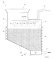
- the powder storage tank 30 has a hopper 92 into which the urea powder 3 is charged, and a side portion 93 and a bottom portion 94 for receiving and holding the urea powder 3 charged from the hopper 92.
- the bottom portion 94 includes a bottom portion 95 at the lowest position and an inclined bottom portion 96 inclined downward toward the bottom portion 95.
- the powder storage tank 30 has the downstream end portion 21 ds of the solvent supply path 21 horizontally passed above the urea powder 3 inside.
- a plurality of watering tools (for example, shower heads) 22 are provided at the downstream end 21 ds of the solvent supply path 21.
- a temperature controller for example, a heater and / or a cooler
- the temperature controller 98 is a temperature that promotes dissolution of the urea powder 3 in water mainly by heating, and a temperature at which no toxic gas is generated from the urea powder 3 mainly by cooling.
- the upstream end of the urea water supply path 31 is connected to the bottom 95 of the powder storage tank 30 through a filter 97.
- the filter 97 allows the high concentration urea water U to pass through without passing the urea powder 3.
- the urea powder 3 is put into the powder storage tank 30 as preparation for departure from the port. And in the ship 10 which left the port, the water required for sailing is refine
- water is dispersed and applied to the upper surface of the urea powder 3 by a plurality of watering tools 22 provided at the downstream end 21 ds of the solvent supply path 21.
- This water permeates from the upper surface of the urea powder 3 to the bottom, and in the process, the urea powder 3 dissolves and becomes high-concentration urea water U.
- the high-concentration urea water U is guided to the bottom portion 95 through the inclined bottom portion 96 or directly, and then is guided to the urea water supply path 31 through the filter 97.
- the high-concentration urea water U in the powder storage tank 30 is first supplied to the measurement tank 32 through the first urea water supply path 31a.
- the high-concentration urea water U in the measurement tank 32 is returned to the powder storage tank 30 by the circulation path 41 if the concentration is less than the predetermined range, and is passed by the second urea water supply path 31b if the concentration is not less than the predetermined range. It is supplied to the adjustment tank 33.
- the high-concentration urea water U returned to the powder storage tank 30 is dispersed again by the plurality of watering tools 22 as a solvent and is spread on the upper surface of the urea powder 3.
- the high-concentration urea water U supplied to the adjustment tank 33 is diluted with water from the dilution path 51 if the concentration exceeds a predetermined range. If the concentration of the high-concentration urea water U falls outside the predetermined range due to insufficient or excessive dilution, the high-concentration urea water U is returned again to the adjustment tank 33 through the concentration adjustment path 61. On the other hand, if the concentration of the high-concentration urea water U in the adjustment tank 33 is within a predetermined range, that is, if the high-concentration urea water U in the adjustment tank 33 becomes an already-adjusted urea water, It is supplied to the service tank 34 through the 3-urea water supply path 31c.
- the service tank 34 a predetermined amount of the adjusted urea water is stored, and a part of the adjusted urea water is supplied to the reduction device 70 through the fourth urea water supply path 31d.
- the adjusted urea water is supplied to the exhaust gas in the exhaust gas path 18 by spraying or the like, and the exhaust gas is purified by being reduced. The purified exhaust gas is discharged by the chimney 8.
- a device for preventing the urea powder 3 from adhering to the powder storage tank 30 is not necessary, and the solution tank for mixing the urea powder 3 and water.
- a stirring device is not required, the size can be reduced and the whole can be simplified.
- the high-concentration urea water U having a concentration below the predetermined range is returned to the powder storage tank 30 as a solvent by the measurement tank 32 and the circulation path 41, the high-concentration urea water U within the predetermined range (that is, the adjusted urea water) ) Can be efficiently generated, in other words, the overall efficiency can be improved.
- the adjustment tank 33, the dilution path 51, and the concentration adjustment path 61 can efficiently generate high-concentration urea water U (that is, already-adjusted urea water) having a concentration within a predetermined range. Efficiency can be improved.
- the dissolution of the urea powder 3 in water is promoted, so that the efficiency can be improved as a whole, and further, generation of toxic gas is prevented, so that safety is improved. Can be improved.
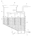
- the exhaust gas purification facility 1 for a marine engine according to Example 2 of the present invention is different from the inside of the powder storage tank 30 in the exhaust gas purification facility 1 for a marine engine according to Example 1 described above.
- a plurality of watering devices 22 are provided at the downstream end 21 ds of the solvent supply path 21 inside the powder storage tank 30. Instead, a plurality of permeation tubes 23 are connected.
- the permeation tube 23 is disposed so as to extend from the upper surface to the bottom of the urea powder 3.
- a large number of openings 24 are formed in the permeation tube 23 for allowing water to permeate from the top surface to the bottom of the urea powder 3.
- the water penetrates not only from the top surface of the urea powder 3 but also from the middle and bottom of the urea powder 3 by the plurality of permeation tubes 23, so that the dissolution of the urea powder 3 in water is promoted.
- the exhaust gas purification facility 1 for a marine engine according to Embodiment 3 of the present invention is different from the inclined bottom portion 96 of the powder storage tank 30 in the exhaust gas purification facility 1 for a marine engine according to Embodiment 1 described above.
- the exhaust gas purification equipment 1 for a marine engine according to Embodiment 3 of the present invention is configured such that powder agitation air (hereinafter simply referred to as air) is supplied from the inclined bottom portion 96 of the powder storage tank 30. That is, the aeration can be used.
- air powder agitation air
- the exhaust gas purification equipment 1 for a marine engine has a large number of air holes 104 that allow the air to pass through the inclined bottom portion 96 and is provided outside the powder storage tank 30. And the air pipe 101 that connects the blower 100 to the inclined bottom portion 96.
- the air is supplied from the blower 100 to the powder storage tank 30 via the air pipe 101 and the inclined bottom portion 96. Then, the urea powder 3 is supplied with air, that is, by aeration, a space through which water passes is secured, and dissolution in water is further promoted.
- the exhaust gas purification equipment 1 for a marine engine according to the third embodiment since the dissolution of the urea powder 3 in water is further promoted, the overall efficiency can be further improved.
- the urea powder 3 has been described as an example of the reducing agent powder.
- the powder is not limited to this, and any powder that can reduce exhaust gas with a solution dissolved in a solvent may be used.
- Examples 1 to 3 water has been described as an example of the solvent. However, the present invention is not limited to this, and any liquid that dissolves the reducing agent powder may be used.
- Embodiments 2 and 3 may be used.
- the powder storage tank 30 in which a large number of air holes 104 are formed in the inclined bottom portion 96 has been described as a configuration in which air is supplied to the urea powder 3.
- the air supply pipe in which a large number of openings are formed is described. May be arranged inside the powder storage tank 30 (for example, like the permeation tube 23 in the second embodiment shown in FIG. 3).
- the relationship between the predetermined range in the concentration of the high-concentration urea water U and the height of the urea powder 3 stored in the powder storage tank 30 was not specifically described.
- the predetermined range is 40% (mass concentration) or more
- the height of the urea powder 3 is preferably 10 cm or more.
- the concentration of the high-concentration urea water U is 40% or more (that is, within the predetermined range), so that it is not returned to the powder storage tank 30 by the circulation path 41. Therefore, it is possible to efficiently generate high-concentration urea water U (that is, already-adjusted urea water) whose concentration is within a predetermined range, in other words, the overall efficiency can be improved.
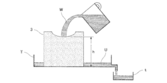
- the relationship between the predetermined range of 40% (mass concentration) and the height of the urea powder 3 of 10 cm or more was obtained by the following experiment. That is, as shown in FIGS. 5 and 6, 1 liter of water W was slowly poured into the mass of urea powder 3 placed in the tray T from above. This water W penetrated from the top surface of the mass of urea powder 3 to the bottom, and in the process, the urea powder 3 was dissolved and became high concentration urea water U and collected in the tray T. The high-concentration urea water U accumulated in the tray T was extracted into another small tray t, and the concentration was measured with a portable urea water concentration meter (PAL-Urea manufactured by Atago Co., Ltd.). The measured concentrations were 40.5%, 41.0%, and 45.3%, respectively, when the height h of the mass of urea powder 3 was 10 cm, 15 cm, and 20 cm.
- PAL-Urea portable urea water concentration meter
Landscapes
- Engineering & Computer Science (AREA)
- Chemical & Material Sciences (AREA)
- Chemical Kinetics & Catalysis (AREA)
- Combustion & Propulsion (AREA)
- Health & Medical Sciences (AREA)
- General Engineering & Computer Science (AREA)
- Mechanical Engineering (AREA)
- Toxicology (AREA)
- Biomedical Technology (AREA)
- Environmental & Geological Engineering (AREA)
- Analytical Chemistry (AREA)
- General Chemical & Material Sciences (AREA)
- Oil, Petroleum & Natural Gas (AREA)
- Exhaust Gas After Treatment (AREA)
- Exhaust Gas Treatment By Means Of Catalyst (AREA)
Abstract
Description
上記還元のための還元剤粉末を貯蔵する粉貯蔵容器と、上記溶媒精製装置により精製された溶媒を上記粉貯蔵容器に供給する溶媒供給経路とを有し、
上記粉貯蔵容器が、上記溶媒供給経路により供給された溶媒に還元剤粉末を溶解させることで、高濃度溶液を生成するものであり、
上記粉貯蔵容器に、上流側から、高濃度溶液の濃度を計測する計測容器と、高濃度溶液の濃度を調整することで当該高濃度溶液を既調整溶液にする調整容器とを有し、
上記粉貯蔵容器により生成された高濃度溶液を上記計測容器に供給する第1溶液供給経路と、上記計測容器の高濃度溶液を上記調整容器に供給する第2溶液供給経路と、上記調整容器の既調整溶液を上記還元装置に供給する既調整溶液供給経路とを有し、
上記還元装置が、上記既調整溶液供給経路により供給された上記既調整溶液を上記排ガスに供給することで、当該排ガスを還元するものである。
上記計測容器が、計測した高濃度溶液の濃度が所定範囲未満であれば、当該高濃度溶液を上記循環経路により粉貯蔵容器に戻すものであり、
上記調整容器が、高濃度溶液の濃度が所定範囲を超えるのであれば、当該高濃度溶液を上記希釈経路からの溶媒により希釈するものである。
上記温度制御機が、粉貯蔵容器の内部を、還元剤粉末の溶媒に対する溶解を促進させる温度、および、還元剤粉末から有毒ガスが発生しない温度に維持するものである。
上記浸透管が、上記粉貯蔵容器における還元剤粉末の上面から底部まで亘るように配置され、
上記浸透管に、上記還元剤粉末の上面から底部に亘って溶媒を浸透させるための開口が多数形成されているものである。
上記空気孔または空気供給管が、粉貯蔵容器における還元剤粉末に空気を供給するものである。
Claims (5)
- 溶媒精製装置、舶用機関および還元装置を備えた船舶において、当該舶用機関からの排ガスを当該還元装置により還元することで浄化する舶用機関の排ガス浄化設備であって、
上記還元のための還元剤粉末を貯蔵する粉貯蔵容器と、上記溶媒精製装置により精製された溶媒を上記粉貯蔵容器に供給する溶媒供給経路とを有し、
上記粉貯蔵容器が、上記溶媒供給経路により供給された溶媒に還元剤粉末を溶解させることで、高濃度溶液を生成するものであり、
上記粉貯蔵容器に、上流側から、高濃度溶液の濃度を計測する計測容器と、高濃度溶液の濃度を調整することで当該高濃度溶液を既調整溶液にする調整容器とを有し、
上記粉貯蔵容器により生成された高濃度溶液を上記計測容器に供給する第1溶液供給経路と、上記計測容器の高濃度溶液を上記調整容器に供給する第2溶液供給経路と、上記調整容器の既調整溶液を上記還元装置に供給する既調整溶液供給経路とを有し、
上記還元装置が、上記既調整溶液供給経路により供給された上記既調整溶液を上記排ガスに供給することで、当該排ガスを還元するものであることを特徴とする舶用機関の排ガス浄化設備。 - 計測容器における高濃度溶液を粉貯蔵容器に戻し得る循環経路と、溶媒精製装置により精製された溶媒を調整容器に供給し得る希釈経路とを有し、
上記計測容器が、計測した高濃度溶液の濃度が所定範囲未満であれば、当該高濃度溶液を上記循環経路により粉貯蔵容器に戻すものであり、
上記調整容器が、高濃度溶液の濃度が所定範囲を超えるのであれば、当該高濃度溶液を上記希釈経路からの溶媒により希釈するものであることを特徴とする請求項1に記載の舶用機関の排ガス浄化設備。 - 粉貯蔵容器に、その内部の温度を制御する温度制御機が設けられ、
上記温度制御機が、粉貯蔵容器の内部を、還元剤粉末の溶媒に対する溶解を促進させる温度、および、還元剤粉末から有毒ガスが発生しない温度に維持するものであることを特徴とする請求項1または2に記載の舶用機関の排ガス浄化設備。 - 溶媒供給経路の粉貯蔵容器側に、還元剤粉末に溶媒を浸透させる浸透管が接続され、
上記浸透管が、上記粉貯蔵容器における還元剤粉末の上面から底部まで亘るように配置され、
上記浸透管に、上記還元剤粉末の上面から底部に亘って溶媒を浸透させるための開口が多数形成されていることを特徴とする請求項1または2に記載の舶用機関の排ガス浄化設備。 - 粉貯蔵容器に空気孔が多数形成され、または、粉貯蔵容器に空気供給管が配置され、
上記空気孔または空気供給管が、粉貯蔵容器における還元剤粉末に空気を供給するものであることを特徴とする請求項1または2に記載の舶用機関の排ガス浄化設備。
Priority Applications (5)
| Application Number | Priority Date | Filing Date | Title |
|---|---|---|---|
| JP2016525779A JP6525990B2 (ja) | 2014-06-03 | 2015-05-26 | 舶用機関の排ガス浄化設備 |
| CN201580029611.1A CN106460602B (zh) | 2014-06-03 | 2015-05-26 | 船用发动机的排气净化设备 |
| KR1020167034300A KR102274549B1 (ko) | 2014-06-03 | 2015-05-26 | 선박용 기관의 배기가스 정화설비 |
| EP15802895.1A EP3153676B1 (en) | 2014-06-03 | 2015-05-26 | Marine engine exhaust gas purification system |
| DK15802895.1T DK3153676T3 (da) | 2014-06-03 | 2015-05-26 | Udstødningsgasrensesystem til skibsmotorer |
Applications Claiming Priority (2)
| Application Number | Priority Date | Filing Date | Title |
|---|---|---|---|
| JP2014-114468 | 2014-06-03 | ||
| JP2014114468 | 2014-06-03 |
Publications (1)
| Publication Number | Publication Date |
|---|---|
| WO2015186559A1 true WO2015186559A1 (ja) | 2015-12-10 |
Family
ID=54766633
Family Applications (1)
| Application Number | Title | Priority Date | Filing Date |
|---|---|---|---|
| PCT/JP2015/064982 Ceased WO2015186559A1 (ja) | 2014-06-03 | 2015-05-26 | 舶用機関の排ガス浄化設備 |
Country Status (6)
| Country | Link |
|---|---|
| EP (1) | EP3153676B1 (ja) |
| JP (1) | JP6525990B2 (ja) |
| KR (1) | KR102274549B1 (ja) |
| CN (1) | CN106460602B (ja) |
| DK (1) | DK3153676T3 (ja) |
| WO (1) | WO2015186559A1 (ja) |
Cited By (2)
| Publication number | Priority date | Publication date | Assignee | Title |
|---|---|---|---|---|
| US10738675B2 (en) * | 2017-03-07 | 2020-08-11 | MAGNETI MARELLI S.p.A. | Method and apparatus to supply water to a tank of an exhaust system provided with exhaust gas after-treatment for a combustion engine |
| JP2022152566A (ja) * | 2021-03-29 | 2022-10-12 | 日立造船株式会社 | 還元剤溶液生成装置 |
Families Citing this family (3)
| Publication number | Priority date | Publication date | Assignee | Title |
|---|---|---|---|---|
| JP6719425B2 (ja) * | 2017-07-05 | 2020-07-08 | ヤンマーパワーテクノロジー株式会社 | 尿素水供給装置 |
| US10655524B2 (en) | 2017-11-03 | 2020-05-19 | Magnetti Marelli S.P.A. | Device to supply an internal combustion engine with water coming from a tank of an exhaust system provided with exhaust gas after-treatment |
| KR102291925B1 (ko) * | 2019-09-24 | 2021-08-23 | 주식회사 동화엔텍 | 선박의 scr용 요소수용액 제조 장치 및 방법 |
Citations (4)
| Publication number | Priority date | Publication date | Assignee | Title |
|---|---|---|---|---|
| JPH03196817A (ja) * | 1989-12-27 | 1991-08-28 | Niigata Eng Co Ltd | 排ガス脱硝装置における尿素水添加量制御方法 |
| US20020023433A1 (en) * | 2000-08-09 | 2002-02-28 | Christian Goerigk | Method and system for feeding a reducing agent into a catalyst device |
| JP2010071148A (ja) * | 2008-09-17 | 2010-04-02 | Yanmar Co Ltd | 船舶におけるエンジンの排気ガス浄化システム |
| US20110126514A1 (en) * | 2009-11-20 | 2011-06-02 | Brammell Jack R | Systems and Methods for On-Site Mixing and Dispensing of a Reducing Agent Solution for Use with a Diesel Catalytic Converter |
Family Cites Families (4)
| Publication number | Priority date | Publication date | Assignee | Title |
|---|---|---|---|---|
| JP3272110B2 (ja) | 1993-06-28 | 2002-04-08 | タテホ化学工業株式会社 | 難燃性樹脂組成物 |
| DE19813722C1 (de) * | 1998-03-27 | 2000-03-23 | Siemens Ag | Verfahren und Vorrichtung zur katalytischen Reduzierung von Stickoxiden im Abgas einer Verbrennungsanlage |
| CN102159455B (zh) * | 2008-09-17 | 2014-04-30 | 洋马株式会社 | 船舶的发动机的废气净化系统 |
| KR20130115504A (ko) * | 2012-04-12 | 2013-10-22 | 삼성중공업 주식회사 | 선박 및 선박의 제어 방법 |
-
2015
- 2015-05-26 CN CN201580029611.1A patent/CN106460602B/zh not_active Expired - Fee Related
- 2015-05-26 JP JP2016525779A patent/JP6525990B2/ja not_active Expired - Fee Related
- 2015-05-26 KR KR1020167034300A patent/KR102274549B1/ko not_active Expired - Fee Related
- 2015-05-26 DK DK15802895.1T patent/DK3153676T3/da active
- 2015-05-26 EP EP15802895.1A patent/EP3153676B1/en not_active Not-in-force
- 2015-05-26 WO PCT/JP2015/064982 patent/WO2015186559A1/ja not_active Ceased
Patent Citations (4)
| Publication number | Priority date | Publication date | Assignee | Title |
|---|---|---|---|---|
| JPH03196817A (ja) * | 1989-12-27 | 1991-08-28 | Niigata Eng Co Ltd | 排ガス脱硝装置における尿素水添加量制御方法 |
| US20020023433A1 (en) * | 2000-08-09 | 2002-02-28 | Christian Goerigk | Method and system for feeding a reducing agent into a catalyst device |
| JP2010071148A (ja) * | 2008-09-17 | 2010-04-02 | Yanmar Co Ltd | 船舶におけるエンジンの排気ガス浄化システム |
| US20110126514A1 (en) * | 2009-11-20 | 2011-06-02 | Brammell Jack R | Systems and Methods for On-Site Mixing and Dispensing of a Reducing Agent Solution for Use with a Diesel Catalytic Converter |
Cited By (2)
| Publication number | Priority date | Publication date | Assignee | Title |
|---|---|---|---|---|
| US10738675B2 (en) * | 2017-03-07 | 2020-08-11 | MAGNETI MARELLI S.p.A. | Method and apparatus to supply water to a tank of an exhaust system provided with exhaust gas after-treatment for a combustion engine |
| JP2022152566A (ja) * | 2021-03-29 | 2022-10-12 | 日立造船株式会社 | 還元剤溶液生成装置 |
Also Published As
| Publication number | Publication date |
|---|---|
| CN106460602A (zh) | 2017-02-22 |
| KR20170016847A (ko) | 2017-02-14 |
| JP6525990B2 (ja) | 2019-06-05 |
| EP3153676B1 (en) | 2019-03-13 |
| EP3153676A1 (en) | 2017-04-12 |
| KR102274549B1 (ko) | 2021-07-06 |
| JPWO2015186559A1 (ja) | 2017-04-20 |
| CN106460602B (zh) | 2019-04-12 |
| DK3153676T3 (da) | 2019-06-03 |
| EP3153676A4 (en) | 2017-06-07 |
Similar Documents
| Publication | Publication Date | Title |
|---|---|---|
| JP6643882B2 (ja) | 燃焼機関の排ガス浄化設備 | |
| WO2015186559A1 (ja) | 舶用機関の排ガス浄化設備 | |
| US11235278B2 (en) | Systems and methods for CO2 sequestration in marine vessels | |
| US9289715B2 (en) | Flue gas scrubbing apparatus and methods thereof | |
| JP2009517210A (ja) | 選択的触媒還元用の多段システム | |
| KR960011040B1 (ko) | 질소 산화물 제거방법과 그 실시에 사용하기 위한 장치 | |
| JP6719425B2 (ja) | 尿素水供給装置 | |
| TWI519338B (zh) | Desulphurization seawater treatment system | |
| JP7128382B1 (ja) | 揮発アンモニアガス処理装置および処理方法 | |
| JP7801944B2 (ja) | 選択式還元触媒システムおよび還元剤噴霧方法 | |
| KR20060115572A (ko) | 가스 정화 방법 및 장치 | |
| KR20160046311A (ko) | 선박의 엔진으로부터 배기 가스를 스크러빙하기 위한 방법 및 시스템 | |
| CN103068739A (zh) | 曝气装置及具备该装置的海水排烟脱硫装置、曝气装置的运转方法 | |
| CN117441057B (zh) | 选择式还原催化剂系统以及还原剂储备方法 | |
| CA3235537A1 (en) | Pollutant removal apparatus and method | |
| TWI454429B (zh) | 曝氣裝置及具備其之海水排煙脫硫裝置、曝氣裝置之運轉方法 | |
| WO2023021719A1 (ja) | 揮発アンモニアガス処理装置および処理方法 | |
| CN208612170U (zh) | 一种船舶尾气处理装置 | |
| JP2022152566A (ja) | 還元剤溶液生成装置 | |
| JP7634307B1 (ja) | 尿素水移送システム、尿素水の移送方法及び尿素水の製造方法 | |
| JPH0710396B2 (ja) | 貯水池等の深層曝気装置 | |
| GB2612035A (en) | Pollutant removal apparatus and method | |
| RU2572132C2 (ru) | Установка для очистки воды каталитическим окислением | |
| JP2005337112A (ja) | 尿素水貯蔵方法 |
Legal Events
| Date | Code | Title | Description |
|---|---|---|---|
| 121 | Ep: the epo has been informed by wipo that ep was designated in this application |
Ref document number: 15802895 Country of ref document: EP Kind code of ref document: A1 |
|
| ENP | Entry into the national phase |
Ref document number: 2016525779 Country of ref document: JP Kind code of ref document: A |
|
| NENP | Non-entry into the national phase |
Ref country code: DE |
|
| ENP | Entry into the national phase |
Ref document number: 20167034300 Country of ref document: KR Kind code of ref document: A |
|
| REEP | Request for entry into the european phase |
Ref document number: 2015802895 Country of ref document: EP |
|
| WWE | Wipo information: entry into national phase |
Ref document number: 2015802895 Country of ref document: EP |