WO2015189983A1 - Dispositif de commande de charge et procédé de commande de charge - Google Patents
Dispositif de commande de charge et procédé de commande de charge Download PDFInfo
- Publication number
- WO2015189983A1 WO2015189983A1 PCT/JP2014/065735 JP2014065735W WO2015189983A1 WO 2015189983 A1 WO2015189983 A1 WO 2015189983A1 JP 2014065735 W JP2014065735 W JP 2014065735W WO 2015189983 A1 WO2015189983 A1 WO 2015189983A1
- Authority
- WO
- WIPO (PCT)
- Prior art keywords
- power
- battery
- charge
- charging
- upper limit
- Prior art date
- Legal status (The legal status is an assumption and is not a legal conclusion. Google has not performed a legal analysis and makes no representation as to the accuracy of the status listed.)
- Ceased
Links
Images


Classifications
-
- H—ELECTRICITY
- H02—GENERATION; CONVERSION OR DISTRIBUTION OF ELECTRIC POWER
- H02J—ELECTRIC POWER NETWORKS; CIRCUIT ARRANGEMENTS OR SYSTEMS FOR SUPPLYING OR DISTRIBUTING ELECTRIC POWER; SYSTEMS FOR STORING ELECTRIC ENERGY
- H02J7/00—Circuit arrangements for charging or discharging batteries or for supplying loads from batteries
- H02J7/02—Circuit arrangements for charging or discharging batteries or for supplying loads from batteries for charging batteries from AC mains by converters
- H02J7/04—Regulation of charging current or voltage
-
- H—ELECTRICITY
- H02—GENERATION; CONVERSION OR DISTRIBUTION OF ELECTRIC POWER
- H02J—ELECTRIC POWER NETWORKS; CIRCUIT ARRANGEMENTS OR SYSTEMS FOR SUPPLYING OR DISTRIBUTING ELECTRIC POWER; SYSTEMS FOR STORING ELECTRIC ENERGY
- H02J7/00—Circuit arrangements for charging or discharging batteries or for supplying loads from batteries
- H02J7/90—Regulation of charging or discharging current or voltage
- H02J7/96—Regulation of charging or discharging current or voltage in response to battery voltage
Definitions
- the present invention relates to a charge control device and a charge control method.
- the PWM control is performed when a request is made to drive the PTC heater pulse-driven by PWM control. Because the driving power of the PTC heater changes (pulsates) at a constant cycle, the charging power of the battery also changes. At this time, in a portion where the driving power of the PTC heater is maximum, a battery charging system is disclosed in which the battery charging power does not exceed the charging allowable power P LIM by discharging the battery. (Patent Document 1).
- the battery voltage is charged by discharging the battery so that the charge power of the battery does not exceed the charge allowable power P LIM due to the pulsation due to the switching operation of PWM control. It does not exceed the upper limit voltage. Further, on the premise that the magnitude of the pulsation due to the switching operation of the PWM control is constant, control is performed so that the charge power of the battery does not exceed the charge allowable power P LIM .
- the problem to be solved by the present invention is a charge control device and a charge method in which the amount of chargeable power of a battery is increased in a system for charging a battery while rectifying AC power by full wave rectification or half wave rectification. It is to provide.
- the present invention manages the chargeable power of the battery as the chargeable power based on the detection value of the sensor and the charge upper limit voltage of the battery, controls the charge power of the battery based on the chargeable power, and has a predetermined charge power.
- the charging upper limit voltage is set to the first charging upper limit voltage if higher than the threshold, and the charging upper limit voltage is set to the second charging upper limit voltage higher than the first charging upper limit voltage if the charging power is lower than the predetermined threshold.
- the present invention increases the chargeable power of the battery because the charge upper limit voltage increases as the pulsation included in the charge power decreases, and the chargeable power of the battery can be increased without reducing the charge efficiency. .
- FIG. 1 It is a block diagram of a charge system concerning an embodiment of the present invention.
- the charging system of FIG. 1 is a graph for demonstrating the pulsation of the charging power of a battery.
- the charge system of FIG. 1 it is a graph for demonstrating the characteristic of charge voltage of a battery.
- FIG. 6 is a graph for explaining the transition of the charging voltage and the charging current of the battery in the charging system of FIG. 1.
- the charge system of FIG. 1 it is a graph which shows the transition over time of the charge electric power and charge voltage of a battery.
- the charge system concerning the modification of the present invention it is a graph for explaining transition of charge voltage and charge current of a battery.
- the charging system which concerns on other embodiment of this invention WHEREIN It is a flowchart which shows the control procedure of a controller.
- the charge system concerning another embodiment of the present invention it is a graph showing transition over time of charge electric power of a battery.
- FIG. 1 is a block diagram of a charging system including a charge control device according to an embodiment of the present invention.
- the charging system according to the present embodiment is a charging system using an inverter of a full wave rectification system or a half wave rectification system.
- the charging system includes an AC power supply 1, a charger 2, a battery 3, a sensor 4, and a controller 5.
- the AC power supply 1 is, for example, a household 100 V or 200 V power supply.
- the charger 2 rectifies AC power supplied from the AC power supply 1 into DC power by full wave rectification or half wave rectification. Further, the charger 2 charges (outputs) the battery 3 as the charging power of the battery 3 as the rectified DC power.
- the charger 2 has a rectifying function, and includes an inverter and the like. Then, based on the control signal transmitted from the controller 5, the inverter of the charger 2 is driven to control the voltage and current to be charged from the charger 2 to the battery 3.
- the battery 3 is configured by connecting a plurality of secondary batteries.
- the sensor 4 is connected to the battery 3 and detects a current (terminal current) and a voltage (terminal voltage) of the battery 3 as detection values indicating the state of the battery 3.
- the detected value of the sensor 4 is output to the controller 5.
- the controller 5 is a controller that controls charging of the battery 3 by controlling an inverter or the like included in the charger 2 based on the detection value of the sensor 4. Specifically, the controller 5 calculates the charging current and the charging voltage to the battery based on the detection value of the sensor 4, that is, the target value of the charging power, and controls the inverter etc. included in the charger 2 It controls so that the effective value (execution electric power) of the charging power charged to 3 becomes a target value.
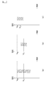
- FIG. 2 is a graph showing the relationship between the effective power and the pulsating component of the charging power obtained by full-wave rectifying AC power and outputting it.
- the charger 2 uses an inverter of full wave rectification or half wave rectification. Therefore, a pulsating flow occurs in the charging power of the charger 2 (the output power actually output from the charger 2).
- the magnitude of the pulsating flow of the charging power is proportional to the magnitude of the effective power.
- the peak value (corresponding to the amplitude) of the charging power is represented by a value obtained by multiplying the effective power (A) by ⁇ 2.
- the peak value of the charging power is represented by a value obtained by multiplying the effective power (B) by ⁇ 2.
- the width of pulsation also decreases.
- the charger 2 is described as full-wave rectification of alternating current power and output, and description on the case of half-wave rectification and output of alternating current power is omitted.
- the cycle of pulsation is twice the commercial frequency of the AC power supply 1.
- Japan has an area with a commercial frequency of 50 Hz and an area with a commercial frequency of 60 Hz.
- the pulsation cycle is 10 msec (100 Hz)
- the pulsation cycle is 8 msec (120 Hz).
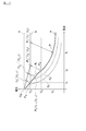
- FIG. 3 is a graph showing the characteristics of the charge voltage of the battery 3.
- (a) shows the characteristics when the battery 3 is charged with an effective power of 3 kW
- (b) and (c) show an effective power of 1 kW. The characteristic at the time of charging the battery 3 is shown.
- a limit voltage (V M ) is previously defined as an upper limit value of the charge voltage.
- V M the limiting voltage is determined based on the voltage at which the deposition of lithium starts.
- the charging upper limit voltage (upper limit value in voltage control) of the battery 3 is set to a voltage lower than the limiting voltage of the battery 3 by a voltage corresponding to pulsation.
- the charging upper limit voltage of the battery 3 may be set to a voltage value lower than the limit voltage in consideration of, for example, a margin including an error of the sensor 4 or the like as well as a voltage of pulsation.
- the voltage of the battery 3 can be charged until the voltage of the battery 3 reaches the charge upper limit voltage while the charge upper limit voltage of the battery 3 is fixed. The amount of power can be charged.
- the charging upper limit voltage of the battery 3 is a fixed value
- the charging upper limit voltage of the battery 3 is greatly restricted, and the charging voltage of the battery 3 is (Battery voltage when charging is completed) will be low.
- charge control is performed to reduce charge power as charging of the battery 3 proceeds.
- the voltage of the battery 3 becomes higher, so the charging power of the battery 3 is reduced by reducing the charging current of the charger 2.
- charge electric power becomes small, pulsation becomes small.
- the charging upper limit voltage is V L1 and charging is performed with 3 kW of charging power (effective power)
- the magnitude of the pulsation is large.
- the peak value of the charging voltage of the battery 3 is substantially equal to the limit voltage (V M ). It is assumed that the charging power (effective power) is reduced from 3 kW to 1 kW from the state shown in FIG. As the charging power decreases, the effective power decreases, so the pulsation decreases.
- the charging voltage can not be increased because the charging upper limit voltage is fixed at VL1 .
- a large voltage difference occurs between the peak value of the charging voltage and the limit voltage. Therefore, the charge voltage can be increased by the amount that the pulsation is reduced, but the charge voltage of the battery 3 is limited to the charge upper limit voltage V L1 , so the charge voltage of the actual battery 3 is limited voltage (V M ) will be greatly restricted. Then, as the charging voltage of the battery 3 does not increase, the amount of power charged to the battery 3 decreases. In addition, since the charging voltage of the battery 3 is low, the charging time becomes long.
- FIG. 4 is a flowchart showing a control procedure of the controller 5.
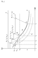
- FIG. 5 is a graph for explaining the transition of the charging voltage and the charging current of the battery 3.
- the graph a is a graph showing the transition of the charging voltage and the charging current of the battery 3 with respect to the transition of charging.
- the charge voltage and charge current of the battery 3 progress on the graph a with respect to the transition of charge.
- the graph b shows the charging upper limit voltage (V L )
- the graph c shows the limiting voltage (V M )
- the graphs d 1 to d 3 show the equivalent power lines of the charging power charged from the charger 2 to the battery 3 ing.
- the charging power decreases in the order of graph d 1 , graph d 2 , and graph d 3 .
- FIG. 6 (a) is a graph for explaining the transition of the charging power of the battery 3, and (b) is a graph for explaining the transition of the charging voltage of the battery 3.
- a graph a shows the chargeable power of the battery 3 and a graph b shows the actual charging voltage (terminal voltage) of the battery 3.
- the graph a shows the limit voltage (V M )
- the graph b shows the charge upper limit voltage (V L ).
- the times (t 1 to t 4 ) and the battery states (P 1 to P 4 ) shown in FIGS. 5 and 6 correspond to each other, and for the transition of charge, the time is t 1 , t 2 , t 3 and t 4 in order.
- the controller 5 detects the charging current and the charging voltage of the battery 3 using the sensor 4 in step S1, and based on the detection value of the battery 3 and the charging upper limit voltage (V L ) The chargeable power of the battery 3 is calculated.
- the chargeable power is charge power required from the current voltage of the battery 3 to the charge upper limit voltage (V L ).
- t 1 time charging start time the state of the (t 1) in the battery 3 (the initial state) and P 1.
- the state (P 1 ) of the battery 3 is represented by a point (P 1 ) in FIG.
- the charge voltage of the battery 3 becomes V 1 and the charge current of the battery 3 is I 1 It becomes.
- the chargeable power is calculated from the voltage and current of the battery 3 detected by the sensor 4 in the state of the battery 3 (P 1 ), the internal resistance of the battery 3 and the charge upper limit voltage (V L ).
- the initial value of the charge upper limit voltage (V L ) is the voltage amplitude at the maximum charge power of the charger 2 from the limit voltage (V M ) (correctly, the voltage amplitude at the maximum charge power is a margin such as a measurement error).
- V 3 is the voltage value obtained by subtracting the considered value).
- the internal resistance may be calculated, for example, from the ratio of the amount of change in the voltage of the battery 3 to the amount of change in the current of the battery 3.
- step S2 the controller 5 compares the chargeable power of the battery 3 with the maximum charge power of the charger 2.
- the maximum charging power of the charger 2 is a power determined according to the supply power of the AC power supply 1 and the performance of the charger 2 and is the maximum power which can charge (output) the battery 3 from the charger 2 It is. If the chargeable power of the battery 3 is larger than the maximum charge power of the charger 2, the state of the battery 3 can be charged with charge power larger than the maximum charge power of the charger 2. Limited to maximum charging power.
- the controller 5 controls the charger 2 as an effective value of the charging power for outputting the maximum charging power of the charger 2 from the charger 2 (step S3). Specifically, charge control of the battery 3 is performed with constant power so that the charging power (effective power) supplied from the charger 2 to the battery becomes the maximum charging power of the charger 2. As charging of the battery 3 proceeds, the voltage of the battery 3 rises. Therefore, the controller 5 gradually decreases the charging current of the battery 3 as the voltage of the battery 3 rises, and sets the charger 2 so that the charging power to the battery 3 becomes the maximum charging power of the charger 2. Control.
- step S1 charge control of constant power based on the maximum charge power of the charger 2 is performed.
- the charge control by the control loop from step S1 to step S3 will be described with reference to FIGS.
- Charging power of the battery 3 is an equivalent power line shown in the graph d 1 in FIG. 5, transitions from the state (P 1) to the state (P 2). As the charging progresses, the voltage of the battery 3 becomes higher, so the charging current of the battery 3 is reduced to I 2 . Also, the current that can be supplied until the charge upper limit voltage (V 3 ) is reached becomes smaller than I 1 ′, and becomes I 2 ′ in the state (P 2 ).
- the current (I 2 ′) is a current that can flow from the state (P 2 ) to the charge upper limit voltage (V 3 ) with respect to the current (I 2 ) of the battery 3.
- the charging upper limit voltage (V L ) is fixed at a constant value (V 3 ). Therefore, as the charging progresses, the chargeable power of the battery 3 decreases.
- the charging power of the battery 3 changes at a constant value of the maximum charging power (Pc) of the charger 2. Further, since the charging power of the battery 3 is the maximum charging power of the charger 2, the pulsation of the charging power is large. As the charging progresses, the charging voltage of the battery 3 is high, but the charging voltage is a sufficiently low value with respect to the charging upper limit voltage (V 3 ). Therefore, as shown in FIG. 6B, the peak value of the charging voltage is suppressed to the charging upper limit voltage (V 3 ) or less.
- the charging upper limit voltage (V L ) when transitioning from the state (P 1 ) to the state (P 2 ), when the chargeable power of the battery 3 is larger than the maximum charge power of the charger 2, The charging power is limited to the maximum charging power of the charger 2. Further, the charging voltage of the battery 3 is sufficiently lower than the limiting voltage (V M ) of the battery 3. Then, as shown in FIG. 6B, even if ripples (pulsations) occur in the voltage of the battery 3 due to the pulsation of the charging power, the peak value of the voltage does not exceed the limit voltage (V M ). Therefore, the charging upper limit voltage (V L ) is set to a fixed value of V 3 .
- step S4 the controller 5 is to raise the upper limit charge voltage of the battery 3, and sets the upper limit charge voltage to a voltage higher than V 3.
- the newly set charging upper limit voltage is a voltage obtained by subtracting the pulsation voltage from the limit voltage (V M ).
- the pulsating voltage is calculated from the charging power with which the battery 2 is charged from the charger 2 and the internal resistance of the battery 3. Since the controller 5 manages the state of the battery 3 and the charging power of the charger 2, it can also calculate the voltage of the pulsation.
- the voltage of pulsation is calculated by referring to the map from the charging power calculated by storing the magnitude of the voltage pulsation (the magnitude of voltage amplitude) against the charging power and the internal resistance in advance by experiment etc. Just do it. Further, since the internal resistance of the battery 3 does not change significantly in a short time of about the charging time, the internal resistance of the battery 3 may be set to a constant value during charging, and the voltage of the pulsation may be calculated based only on the charging power. . Then, the controller 5 calculates the charge upper limit voltage to be set by subtracting the voltage for the pulsation from the limit voltage (V M ).
- the charging power of the battery 3 becomes lower along with the transition of the charge. Then, as described above, when the charging power of the battery 3 becomes low, the pulsation of the charging power also becomes small. As a result, the voltage of the pulsation that is subtracted from the limit voltage (V M ) also decreases, and the charging upper limit voltage increases. In addition, since the voltage of the pulsation component changes in accordance with the change of the charging power, the charging upper limit voltage is also set to a variable value in this example.
- step S5 the controller 5 calculates chargeable power.
- the method of calculating the chargeable power is the same as in step S1. At this time, since the charge upper limit voltage is higher than V 3 , the chargeable power of the battery 3 is large.
- step S6 the controller 5 controls the charger 2 based on the chargeable power of the battery 3.
- the controller 5 controls the charge of the battery 3 so that the effective value of the charging power charged from the charger 2 to the battery 3 becomes the chargeable power.
- step S7 the controller 5 compares the target voltage indicating that the battery 3 is fully charged with the detection voltage of the sensor 4 to determine whether the detection voltage of the battery 3 is lower than the target voltage. When the charge voltage of the battery 3 is lower than the target voltage, the controller 5 determines that the battery is not fully charged, and returns to step S4.
- step S4 the charge upper limit voltage (V L ) rises according to the decrease in pulsation, and the chargeable power is increased, and charge control based on the chargeable power is performed. It will be.
- step S4 The charge control by the control loop from step S4 to step S7 will be described using FIGS.
- the power charged from the charger 2 to the battery 3 decreases. Therefore, in the graph shown in FIG. 5, the state of the battery deviates from the equivalent power line (d 1 ) and shifts sequentially to the state (P 3 ) and the state (P 4 ).
- the charging upper limit voltage (V 3 ) As the charging progresses, the voltage of the battery 3 becomes higher. Therefore, when the charging upper limit voltage (V 3 ) is a fixed value, the chargeable power of the battery 3 is small.
- the charging upper limit voltage (V 3 ) gradually increases. For example, when the state of the battery 3 is transitioning from P 2 to P 3, charging upper limit voltage is higher from V 3 to V 3_1.
- the charging voltage of the battery 3 is V 2_1 and the charging current is I 2_1 .
- the current that can be supplied until the charge upper limit voltage (V 3 _ 1 ) is reached is I 2 _ 1 ′.
- the charging upper limit voltage is increased from V 3 to V 3_1, state voltage difference between the voltage (V 2_1) and charge upper limit voltage (V L) of (P 3) is a charging upper limit voltage V 3 It becomes large compared with the case of fixed value of. Further, the current which can flow from the state (P 3 ) of the battery 3 to the charging upper limit voltage is also larger than when the charging upper limit voltage is a fixed value of V 3 . Therefore, the chargeable power of the battery 3 is larger than when the charge upper limit voltage (V 3 ) is a fixed value.
- the chargeable power of the battery 3 is larger than when the charging upper limit voltage (V 3 ) is a fixed value.
- the charging power of the battery 3 becomes lower as the charging of the battery 3 proceeds.
- the pulsation of the charging power also gradually decreases, and the voltage amplitude (pulsation) also decreases accordingly.
- the charging voltage of the battery 3 increases and the charging upper limit voltage (V L ) also increases, but the pulsation gradually decreases. Therefore, as shown in FIG. 6B, the peak value of the charging voltage is suppressed to the charging upper limit voltage (V L ) or less.
- controller 5 sets the charging upper limit voltage to V 3 when the charge power of battery 3 is higher than the maximum charge power of charger 2, and the charge power of battery 3 is the maximum charge of charger 2. higher V 3_1 than V 3 the charging upper limit voltage is lower than the power is set to V 3_2. Since the voltage of the battery 3 at the end of charging becomes higher than V 3 , the chargeable power amount of the battery 3 can be increased.
- step S7 when the charging voltage of the battery 3 is equal to or higher than the target voltage, the controller 5 determines that the battery is fully charged, and proceeds to step S8. Then, the controller 5 stops the charging of the battery 3 by stopping the charger 2, and the control flow of the present example ends.
- the controller 5 manages the chargeable power of the battery 3 based on the detected value of the sensor 4 and the charge upper limit voltage of the battery 3 and charges the battery 3 based on the chargeable power. Control the power. Then, when the charge power of battery 3 is higher than the maximum charge power of charger 2, controller 5 sets the charge upper limit voltage to V 3, and the charge power of battery 3 is lower than the maximum charge power of charger 2 case, sets the upper limit charge voltage to a voltage higher than V 3. As a result, when the charging power of the battery 3 decreases and the pulsation of the charging power decreases, the charging upper limit voltage increases. Therefore, the chargeable power of the battery is increased, and the chargeable power of the battery can be increased.
- the controller 5 raises the charge upper limit voltage as the charge of the battery 3 proceeds.
- the charging power of the battery 3 is reduced, so the pulsation gradually decreases.
- the decrease amount of the pulsation width which becomes gradually smaller is allocated to the increase amount of the chargeable power.
- the controller 5 may correct the chargeable power according to the degree of deterioration of the battery 3, the temperature of the battery 3, the SOC of the battery 3, and the like.
- the controller 5 corrects the internal resistance according to the degree of deterioration of the battery 3, the temperature, the SOC, and the like, and calculates the chargeable power such that the chargeable power decreases as the internal resistance increases.
- the temperature of the battery 3 may be detected by a temperature sensor.
- the controller 5 may correct the increase width of the charging upper limit voltage in accordance with the degree of deterioration of the battery 3, temperature, SOC and the like.
- the controller 5 calculates the charging upper limit voltage so as to reduce the rising width of the charging upper limit voltage as the internal resistance increases.
- the charging upper limit voltage is increased according to the smaller charging power, but the charging upper limit voltage may be increased according to the chargeable power of the battery 3, and the charging upper limit according to the charging current of the battery 3
- the voltage may be increased, or the charging upper limit voltage may be increased according to the voltage difference between the current voltage of the battery 3 and the control voltage (V M ).
- the controller 5 may set the charge upper limit voltage so that the charge upper limit voltage becomes higher as the chargeable power becomes lower.
- the charging current of the battery 3 and the voltage difference between the current voltage of the battery 3 and the control voltage (V M ) may be set similarly to the chargeable power.
- the present invention changes the charge upper limit voltage depending on whether the chargeable power of the battery 3 is larger than the maximum charge power of the charger 2 while using the maximum charge power of the charger 2 as the threshold, the threshold is not necessarily charged It is not necessary to set the maximum charging power of the unit 2. For example, when the chargeable power of battery 3 (ie, the chargeable power of battery 3) is higher than a predetermined power threshold when the chargeable power of battery 3 is lower than the maximum charge power of charger 2, controller 5 Sets the charging upper limit voltage to V x , and when the charge power of the battery 3 is lower than the predetermined power threshold, the controller 5 sets the charging upper limit voltage to V y higher than V x .
- variable control of the charge upper limit voltage can be performed based on comparison between the charge power of the battery 3 and the threshold value.
- the present invention is also applicable to constant voltage charge control or constant current charge control.
- FIG. 7 is a graph for explaining the transition of the charging voltage and the charging current of the battery 3 in the charge control device according to the modification.
- the graphs a to c and the graphs d 1 to d 3 in FIG. 7 are the same as the graphs shown in FIG.
- the controller 5 sets the charging upper limit voltage to V 3 as an initial value (corresponding to the state of the battery 3 (P 1 )). Charging of the battery 3 proceeds, when the chargeable power of the battery 3 is lower than the first power threshold value of the charger 2, the controller 5 sets the charging upper limit voltage from V 3 to V 3_1.
- the first power threshold is a threshold of charging power set in advance, and is set to a value equal to or less than the maximum power threshold of the charger 2. In FIG. 7, when the chargeable power of the battery 3 is the first power threshold, the charge voltage of the battery 3 is V 2 . Further, the charging upper limit voltage (V 3 _ 1 ) is higher than the charging upper limit voltage (V 3 ).
- the controller 5 sets the charging upper limit voltage from V3_1 to V3_2 .
- the second power threshold is a threshold of charging power set in advance, and is set to a value lower than the first power threshold.
- the charge voltage of the battery 3 is V 2 _ 1 .
- the charging upper limit voltage (V 3 _ 2 ) is higher than the charging upper limit voltage (V 3 _ 1 ).
- the controller 5 sets the charging upper limit voltage from V3_2 to V3_3 .
- the third power threshold is a threshold of charging power set in advance, and is set to a value lower than the second power threshold.
- the charge voltage of the battery 3 is V 2_2 .
- the charging upper limit voltage (V 3_3) is higher than the charging upper limit voltage (V 3_2).
- the controller 5 described above corresponds to the control means of the present invention.
- Second Embodiment A charging system according to another embodiment of the present invention will be described.
- control of charging power when changing the charging upper limit voltage to a high voltage is different from the first embodiment described above.
- the other configuration is the same as that of the first embodiment described above, and the description thereof is incorporated.
- FIG. 8 is a flowchart showing a control flow of the controller 5.
- FIG. 9 is a graph for explaining the temporal transition of the charging power of the battery 3.
- step S11 to step S13 is the same as the control flow from step S1 to step S3 according to the first embodiment, and therefore the description will be omitted.
- step S14 the controller 5 controls the charger 2 such that the charging power from the charger 2 to the battery 3 becomes the chargeable power.
- step S15 the controller 5 compares the charging power of the battery 3 with the power threshold.
- the power threshold is a threshold that represents the timing for changing the charging upper limit voltage by charging power, and is preset. If the charge power of the battery 3 is higher than the power threshold, the controller 5 returns to step S14 while calculating the chargeable power of the battery 3 in step S16. In charge control corresponding to the control loop of steps S14 to S16, the charge upper limit voltage remains set to the initial value (V p ).
- step S17 the controller 5 changes the charging upper limit voltage from V p to V s .
- the charging upper limit voltage (V s ) is higher than the initial charging upper limit voltage (V p ).
- the rise width of the charging upper limit voltage is predetermined. However, at the time of step S17, even if the charging upper limit voltage is changed, the charging power is not changed.
- step S18 controller 5 reaches the charge upper limit voltage (V s ) from the current state of battery 3 (current voltage of battery 3) while detecting the current state of battery 3 from the detection value of sensor 4 Calculate the necessary chargeable power.
- V s charge upper limit voltage
- the method of calculating the chargeable power is the same as the control flow of step S11.
- the chargeable power calculated in the control flow of step S18 is referred to as necessary charge power for the sake of convenience.
- step S19 the controller 5 compares the required charging power with the power threshold.
- the power threshold is the same value as the power threshold used in the control flow of step S15. If the required charging power is higher than the power threshold, the process proceeds to step S20.
- step S20 the controller 5 controls the charger 2 so that the charge power of the battery 3 becomes the power threshold. That is, the controller 5 controls the charging of the battery 3 with the constant power of the power threshold. Then, the process returns to step S18.
- the controller 5 changes the charging upper limit voltage from V p to V s (corresponding to step S17).
- P 1 indicates the state of the battery at time (t 2 ).
- P 1 ′ indicates the virtual state of the battery 3 when the charging power is increased to the required charging power at time (t 2 ).
- the graph b shows the temporal transition of the charging power when the charging power is the chargeable power calculated based on the charging upper limit voltage (V s ).
- the charging upper limit voltage becomes high, the chargeable power instantaneously increases. At this time, if the charging power is also increased momentarily according to the chargeable power, the pulsation of the charging power is also increased, so the peak value of the charging voltage may be instantaneously higher than the limit voltage (V M ). . Therefore, in the present invention, when the charging upper limit voltage is increased (time t 2 ), charging of the battery 3 is controlled with constant power using charging power at the time of changing the charging upper limit voltage without increasing the charging power. That is, the state of the battery 3 is not to transition from P 1 to P 1 '. Also, the charging power changes at a constant value of the power threshold (P th ).
- the required charging power becomes equal to the power threshold (P th ) at time (t 3 ). That is, in step 19, the timing at which the required charging power becomes equal to or less than the power threshold corresponds to time (t 3 ).
- step S21 the controller 5 controls the charger 2 so that the necessary charging power becomes the charging power of the battery 3.
- step S22 the controller 5 determines whether the battery 3 is fully charged.
- step S23 the controller 5 while calculating the required charging power of the battery 3 (the chargeable electric power based on the charging upper limit voltage V s), the flow returns to step S21.
- the controller 5 stops the charging of the battery 3 by stopping the charger 2 (step S24), and the control flow of the present example ends.
- the required charge power is lower than the power threshold after time (t 3 )
- the peak value of the charge voltage is Do not exceed the limit voltage (V M ).
- the chargeable power is calculated based on the charge upper limit voltage after the change and the charge control is performed so that the charge power becomes the chargeable power, the voltage of the battery 3 becomes high. Thereby, the chargeable electric energy of the battery 3 can be increased.
- the controller 5 can charge necessary for reaching the charge upper limit voltage (V s ) from the current state of the battery 3 based on the sensor 4 detection value and the charge upper limit voltage (V s ) Calculate the power (necessary charging power). Then, when the charging power is equal to or less than the predetermined power threshold (P th ), the controller 5 sets the lower one of the power threshold (P th ) and the necessary charging power as the charging power of the battery 3. As a result, when the charging upper limit voltage is set to a high value, the peak value of the charging voltage can be suppressed to the limit voltage (V M ) or less.
- the constant power value settable as charging power may be a power value lower than the power threshold (P th ). Also, of the control flow in FIG. 8, step S19, the control flow of steps S20, and S21 correspond to the control of the time t 2 later select low.
- the charge upper limit voltage is changed in one step, it is not limited to one step and may be plural.
- the charging upper limit voltage (V p ) corresponds to the first charging upper limit voltage
- the charging upper limit voltage (V s ) corresponds to the second charging upper limit voltage
Landscapes
- Engineering & Computer Science (AREA)
- Power Engineering (AREA)
- Charge And Discharge Circuits For Batteries Or The Like (AREA)
- Secondary Cells (AREA)
Abstract
Priority Applications (5)
| Application Number | Priority Date | Filing Date | Title |
|---|---|---|---|
| CN201480079820.2A CN106463997B (zh) | 2014-06-13 | 2014-06-13 | 充电控制装置以及充电控制方法 |
| PCT/JP2014/065735 WO2015189983A1 (fr) | 2014-06-13 | 2014-06-13 | Dispositif de commande de charge et procédé de commande de charge |
| EP14894704.7A EP3157131B1 (fr) | 2014-06-13 | 2014-06-13 | Dispositif de commande de charge et procédé de commande de charge |
| US15/318,326 US9742217B2 (en) | 2014-06-13 | 2014-06-13 | Charge control apparatus and charge control method |
| JP2016527592A JP6187692B2 (ja) | 2014-06-13 | 2014-06-13 | 充電制御装置及び充電制御方法 |
Applications Claiming Priority (1)
| Application Number | Priority Date | Filing Date | Title |
|---|---|---|---|
| PCT/JP2014/065735 WO2015189983A1 (fr) | 2014-06-13 | 2014-06-13 | Dispositif de commande de charge et procédé de commande de charge |
Publications (1)
| Publication Number | Publication Date |
|---|---|
| WO2015189983A1 true WO2015189983A1 (fr) | 2015-12-17 |
Family
ID=54833111
Family Applications (1)
| Application Number | Title | Priority Date | Filing Date |
|---|---|---|---|
| PCT/JP2014/065735 Ceased WO2015189983A1 (fr) | 2014-06-13 | 2014-06-13 | Dispositif de commande de charge et procédé de commande de charge |
Country Status (5)
| Country | Link |
|---|---|
| US (1) | US9742217B2 (fr) |
| EP (1) | EP3157131B1 (fr) |
| JP (1) | JP6187692B2 (fr) |
| CN (1) | CN106463997B (fr) |
| WO (1) | WO2015189983A1 (fr) |
Cited By (5)
| Publication number | Priority date | Publication date | Assignee | Title |
|---|---|---|---|---|
| JP2017184450A (ja) * | 2016-03-30 | 2017-10-05 | 住友電気工業株式会社 | 電力変換装置並びに蓄電池の充電制御方法及び放電制御方法 |
| JP2018525962A (ja) * | 2016-02-05 | 2018-09-06 | 広東欧珀移動通信有限公司 | 端末用充電システム、充電方法及び端末 |
| WO2019049571A1 (fr) * | 2017-09-11 | 2019-03-14 | パナソニックIpマネジメント株式会社 | Système accumulateur d'électricité et dispositif de gestion |
| WO2019163301A1 (fr) * | 2018-02-23 | 2019-08-29 | パナソニックIpマネジメント株式会社 | Dispositif de gestion, et système de stockage d'électricité |
| CN110710050A (zh) * | 2017-06-08 | 2020-01-17 | 松下知识产权经营株式会社 | 蓄电系统、管理装置 |
Families Citing this family (10)
| Publication number | Priority date | Publication date | Assignee | Title |
|---|---|---|---|---|
| CN105572599B (zh) * | 2014-09-04 | 2019-08-20 | 中兴通讯股份有限公司 | 一种显示电池的电量的方法、装置及电子设备 |
| JP6536466B2 (ja) * | 2016-04-27 | 2019-07-03 | 株式会社オートネットワーク技術研究所 | 電源装置 |
| CN107611510B (zh) * | 2017-08-31 | 2020-03-17 | 苏州新中能源科技有限公司 | 充电控制方法及充电控制装置 |
| KR102269106B1 (ko) | 2017-11-20 | 2021-06-24 | 주식회사 엘지화학 | 배터리 파워 한계 값 제어 방법 |
| WO2020137815A1 (fr) * | 2018-12-25 | 2020-07-02 | 三洋電機株式会社 | Dispositif d'alimentation électrique en veille et procédé de charge de pile rechargeable |
| CN109861337B (zh) * | 2019-03-05 | 2020-09-04 | Oppo广东移动通信有限公司 | 电子设备、充电方法及存储介质 |
| US12584971B2 (en) * | 2020-02-04 | 2026-03-24 | Vehicle Energy Japan Inc. | Battery management apparatus, battery management method, and battery energy storage system |
| US20220200295A1 (en) * | 2020-12-23 | 2022-06-23 | Medtronic, Inc. | Systems and method for charging batteries |
| CN116325285B (zh) * | 2021-02-23 | 2025-09-16 | 宁德时代新能源科技股份有限公司 | 一种充电控制方法、装置和电源管理控制器 |
| CN119315177A (zh) * | 2024-10-10 | 2025-01-14 | 江西云杉智能科技有限公司 | 电池组件的控制方法、控制装置及叉车 |
Citations (3)
| Publication number | Priority date | Publication date | Assignee | Title |
|---|---|---|---|---|
| JP2002034172A (ja) * | 2000-07-17 | 2002-01-31 | Nec Mobile Energy Kk | 充電器システム |
| JP2009022078A (ja) * | 2007-07-10 | 2009-01-29 | Sanyo Electric Co Ltd | リチウムイオン二次電池の充電方法 |
| WO2014046234A1 (fr) * | 2012-09-21 | 2014-03-27 | 日産自動車株式会社 | Dispositif de commande de charge et procédé de calcul du temps de charge |
Family Cites Families (8)
| Publication number | Priority date | Publication date | Assignee | Title |
|---|---|---|---|---|
| JP2004328934A (ja) * | 2003-04-25 | 2004-11-18 | Japan Storage Battery Co Ltd | バッテリの充電制御装置 |
| JP4406932B2 (ja) * | 2005-09-13 | 2010-02-03 | 日立工機株式会社 | 充電装置 |
| JP4952031B2 (ja) * | 2006-04-14 | 2012-06-13 | トヨタ自動車株式会社 | 電源装置および電源装置における入出力制限設定方法並びに車両およびその制御方法 |
| JP4966998B2 (ja) * | 2009-06-18 | 2012-07-04 | パナソニック株式会社 | 充電制御回路、電池パック、及び充電システム |
| JP5503318B2 (ja) * | 2010-02-05 | 2014-05-28 | 古河電気工業株式会社 | 二次電池の充電受入れ限界検知方法及びその装置 |
| JP5821256B2 (ja) | 2010-06-09 | 2015-11-24 | 日産自動車株式会社 | バッテリ充電システム |
| JP2014011925A (ja) * | 2012-07-02 | 2014-01-20 | Omron Automotive Electronics Co Ltd | 充電装置 |
| WO2014045942A1 (fr) * | 2012-09-24 | 2014-03-27 | 日産自動車株式会社 | Dispositif de commande de charge et procédé de commande de charge |
-
2014
- 2014-06-13 EP EP14894704.7A patent/EP3157131B1/fr active Active
- 2014-06-13 JP JP2016527592A patent/JP6187692B2/ja active Active
- 2014-06-13 WO PCT/JP2014/065735 patent/WO2015189983A1/fr not_active Ceased
- 2014-06-13 US US15/318,326 patent/US9742217B2/en active Active
- 2014-06-13 CN CN201480079820.2A patent/CN106463997B/zh active Active
Patent Citations (3)
| Publication number | Priority date | Publication date | Assignee | Title |
|---|---|---|---|---|
| JP2002034172A (ja) * | 2000-07-17 | 2002-01-31 | Nec Mobile Energy Kk | 充電器システム |
| JP2009022078A (ja) * | 2007-07-10 | 2009-01-29 | Sanyo Electric Co Ltd | リチウムイオン二次電池の充電方法 |
| WO2014046234A1 (fr) * | 2012-09-21 | 2014-03-27 | 日産自動車株式会社 | Dispositif de commande de charge et procédé de calcul du temps de charge |
Cited By (13)
| Publication number | Priority date | Publication date | Assignee | Title |
|---|---|---|---|---|
| JP2018525962A (ja) * | 2016-02-05 | 2018-09-06 | 広東欧珀移動通信有限公司 | 端末用充電システム、充電方法及び端末 |
| US10491030B2 (en) | 2016-02-05 | 2019-11-26 | Guangdong Oppo Mobile Telecommunications Corp., Ltd. | Charging system and charging method for terminal and terminal |
| JP2017184450A (ja) * | 2016-03-30 | 2017-10-05 | 住友電気工業株式会社 | 電力変換装置並びに蓄電池の充電制御方法及び放電制御方法 |
| US11277013B2 (en) | 2017-06-08 | 2022-03-15 | Panasonic Intellectual Property Management Co., Ltd. | Power storage system having a plurality of power storage blocks interconnected in parallel and control device |
| CN110710050B (zh) * | 2017-06-08 | 2023-02-17 | 松下知识产权经营株式会社 | 蓄电系统、管理装置 |
| CN110710050A (zh) * | 2017-06-08 | 2020-01-17 | 松下知识产权经营株式会社 | 蓄电系统、管理装置 |
| US11329327B2 (en) | 2017-09-11 | 2022-05-10 | Panasonic Intellectual Property Management Co., Ltd. | Electricity storage system and management device |
| JPWO2019049571A1 (ja) * | 2017-09-11 | 2020-08-20 | パナソニックIpマネジメント株式会社 | 蓄電システム、管理装置 |
| JP7117534B2 (ja) | 2017-09-11 | 2022-08-15 | パナソニックIpマネジメント株式会社 | 蓄電システム、管理装置 |
| WO2019049571A1 (fr) * | 2017-09-11 | 2019-03-14 | パナソニックIpマネジメント株式会社 | Système accumulateur d'électricité et dispositif de gestion |
| JPWO2019163301A1 (ja) * | 2018-02-23 | 2021-03-11 | パナソニックIpマネジメント株式会社 | 管理装置、蓄電システム |
| WO2019163301A1 (fr) * | 2018-02-23 | 2019-08-29 | パナソニックIpマネジメント株式会社 | Dispositif de gestion, et système de stockage d'électricité |
| JP7149543B2 (ja) | 2018-02-23 | 2022-10-07 | パナソニックIpマネジメント株式会社 | 管理装置、蓄電システム |
Also Published As
| Publication number | Publication date |
|---|---|
| US9742217B2 (en) | 2017-08-22 |
| US20170126052A1 (en) | 2017-05-04 |
| EP3157131A1 (fr) | 2017-04-19 |
| EP3157131A4 (fr) | 2017-05-24 |
| JPWO2015189983A1 (ja) | 2017-04-20 |
| CN106463997B (zh) | 2018-04-06 |
| EP3157131B1 (fr) | 2019-04-17 |
| JP6187692B2 (ja) | 2017-09-06 |
| CN106463997A (zh) | 2017-02-22 |
Similar Documents
| Publication | Publication Date | Title |
|---|---|---|
| JP6187692B2 (ja) | 充電制御装置及び充電制御方法 | |
| US8803473B2 (en) | Pulse modulation charging method and apparatus | |
| CN106374595B (zh) | 非接触送电装置以及电力传输系统 | |
| JP6431276B2 (ja) | バッテリー充電システムおよびバッテリー充電方法 | |
| CN108233696B (zh) | 控制脉冲宽度调制开关频率的装置和方法 | |
| JP5822304B2 (ja) | 充電装置 | |
| US20170033696A1 (en) | Power conversion apparatus | |
| CN101872994A (zh) | 电池充电器及其充电方法 | |
| JP2010136463A (ja) | 電力伝送装置 | |
| CN104769806A (zh) | 用于对电池进行充电的方法和装置 | |
| RU2633696C2 (ru) | Способ, устройство и носитель данных для управления пуском импульсного выпрямителя | |
| JP5967204B2 (ja) | 二次電池の充電装置および二次電池の充電方法 | |
| US12149179B2 (en) | Power converter with controller alternately turning on switches | |
| JP2004187496A (ja) | 多数のバッテリの充電方法及び装置 | |
| JP2013192348A (ja) | 二次電池の充電装置および二次電池の充電方法 | |
| CN110504762B (zh) | 无线电力发送设备和电力传输系统 | |
| CN110870184B (zh) | 电源装置、驱动装置、控制方法以及存储介质 | |
| US10897159B2 (en) | Wireless power transmission device and wireless power transfer system | |
| JP6962272B2 (ja) | 非接触送電装置及び電力伝送システム | |
| JP2012222951A (ja) | 充電装置 | |
| CN110875639B (zh) | 电力传输装置、电力接收装置和电力传输装置的控制方法 | |
| JP2008253094A (ja) | 電源供給回路及びそのpam制御方法 | |
| JP6223612B1 (ja) | 電力変換制御装置 | |
| CN109888931B (zh) | 无线电力传输设备和电力传输系统 | |
| CN110932371A (zh) | 无线充电发射器、控制方法及谐振式无线充电系统 |
Legal Events
| Date | Code | Title | Description |
|---|---|---|---|
| 121 | Ep: the epo has been informed by wipo that ep was designated in this application |
Ref document number: 14894704 Country of ref document: EP Kind code of ref document: A1 |
|
| ENP | Entry into the national phase |
Ref document number: 2016527592 Country of ref document: JP Kind code of ref document: A |
|
| WWE | Wipo information: entry into national phase |
Ref document number: 15318326 Country of ref document: US |
|
| NENP | Non-entry into the national phase |
Ref country code: DE |
|
| REEP | Request for entry into the european phase |
Ref document number: 2014894704 Country of ref document: EP |
|
| WWE | Wipo information: entry into national phase |
Ref document number: 2014894704 Country of ref document: EP |