WO2015190075A1 - アニオン交換形電解質膜、それを備えた燃料電池用の膜-電極接合体及び燃料電池 - Google Patents
アニオン交換形電解質膜、それを備えた燃料電池用の膜-電極接合体及び燃料電池 Download PDFInfo
- Publication number
- WO2015190075A1 WO2015190075A1 PCT/JP2015/002820 JP2015002820W WO2015190075A1 WO 2015190075 A1 WO2015190075 A1 WO 2015190075A1 JP 2015002820 W JP2015002820 W JP 2015002820W WO 2015190075 A1 WO2015190075 A1 WO 2015190075A1
- Authority
- WO
- WIPO (PCT)
- Prior art keywords
- anion exchange
- resin
- graft
- electrolyte membrane
- group
- Prior art date
- Legal status (The legal status is an assumption and is not a legal conclusion. Google has not performed a legal analysis and makes no representation as to the accuracy of the status listed.)
- Ceased
Links
Images


Classifications
-
- H—ELECTRICITY
- H01—ELECTRIC ELEMENTS
- H01M—PROCESSES OR MEANS, e.g. BATTERIES, FOR THE DIRECT CONVERSION OF CHEMICAL ENERGY INTO ELECTRICAL ENERGY
- H01M8/00—Fuel cells; Manufacture thereof
- H01M8/10—Fuel cells with solid electrolytes
- H01M8/1016—Fuel cells with solid electrolytes characterised by the electrolyte material
- H01M8/1018—Polymeric electrolyte materials
- H01M8/102—Polymeric electrolyte materials characterised by the chemical structure of the main chain of the ion-conducting polymer
- H01M8/1025—Polymeric electrolyte materials characterised by the chemical structure of the main chain of the ion-conducting polymer having only carbon and oxygen, e.g. polyethers, sulfonated polyetheretherketones [S-PEEK], sulfonated polysaccharides, sulfonated celluloses or sulfonated polyesters
-
- C—CHEMISTRY; METALLURGY
- C08—ORGANIC MACROMOLECULAR COMPOUNDS; THEIR PREPARATION OR CHEMICAL WORKING-UP; COMPOSITIONS BASED THEREON
- C08F—MACROMOLECULAR COMPOUNDS OBTAINED BY REACTIONS ONLY INVOLVING CARBON-TO-CARBON UNSATURATED BONDS
- C08F261/00—Macromolecular compounds obtained by polymerising monomers on to polymers of oxygen-containing monomers as defined in group C08F16/00
- C08F261/02—Macromolecular compounds obtained by polymerising monomers on to polymers of oxygen-containing monomers as defined in group C08F16/00 on to polymers of unsaturated alcohols
- C08F261/04—Macromolecular compounds obtained by polymerising monomers on to polymers of oxygen-containing monomers as defined in group C08F16/00 on to polymers of unsaturated alcohols on to polymers of vinyl alcohol
-
- B—PERFORMING OPERATIONS; TRANSPORTING
- B01—PHYSICAL OR CHEMICAL PROCESSES OR APPARATUS IN GENERAL
- B01J—CHEMICAL OR PHYSICAL PROCESSES, e.g. CATALYSIS OR COLLOID CHEMISTRY; THEIR RELEVANT APPARATUS
- B01J41/00—Anion exchange; Use of material as anion exchangers; Treatment of material for improving the anion exchange properties
- B01J41/08—Use of material as anion exchangers; Treatment of material for improving the anion exchange properties
- B01J41/12—Macromolecular compounds
- B01J41/14—Macromolecular compounds obtained by reactions only involving unsaturated carbon-to-carbon bonds
-
- C—CHEMISTRY; METALLURGY
- C08—ORGANIC MACROMOLECULAR COMPOUNDS; THEIR PREPARATION OR CHEMICAL WORKING-UP; COMPOSITIONS BASED THEREON
- C08J—WORKING-UP; GENERAL PROCESSES OF COMPOUNDING; AFTER-TREATMENT NOT COVERED BY SUBCLASSES C08B, C08C, C08F, C08G or C08H
- C08J5/00—Manufacture of articles or shaped materials containing macromolecular substances
- C08J5/20—Manufacture of shaped structures of ion-exchange resins
- C08J5/22—Films, membranes or diaphragms
-
- C—CHEMISTRY; METALLURGY
- C08—ORGANIC MACROMOLECULAR COMPOUNDS; THEIR PREPARATION OR CHEMICAL WORKING-UP; COMPOSITIONS BASED THEREON
- C08J—WORKING-UP; GENERAL PROCESSES OF COMPOUNDING; AFTER-TREATMENT NOT COVERED BY SUBCLASSES C08B, C08C, C08F, C08G or C08H
- C08J5/00—Manufacture of articles or shaped materials containing macromolecular substances
- C08J5/20—Manufacture of shaped structures of ion-exchange resins
- C08J5/22—Films, membranes or diaphragms
- C08J5/2206—Films, membranes or diaphragms based on organic and/or inorganic macromolecular compounds
- C08J5/2218—Synthetic macromolecular compounds
- C08J5/2231—Synthetic macromolecular compounds based on macromolecular compounds obtained by reactions involving unsaturated carbon-to-carbon bonds
- C08J5/2243—Synthetic macromolecular compounds based on macromolecular compounds obtained by reactions involving unsaturated carbon-to-carbon bonds obtained by introduction of active groups capable of ion-exchange into compounds of the type C08J5/2231
-
- C—CHEMISTRY; METALLURGY
- C08—ORGANIC MACROMOLECULAR COMPOUNDS; THEIR PREPARATION OR CHEMICAL WORKING-UP; COMPOSITIONS BASED THEREON
- C08L—COMPOSITIONS OF MACROMOLECULAR COMPOUNDS
- C08L101/00—Compositions of unspecified macromolecular compounds
-
- H—ELECTRICITY
- H01—ELECTRIC ELEMENTS
- H01B—CABLES; CONDUCTORS; INSULATORS; SELECTION OF MATERIALS FOR THEIR CONDUCTIVE, INSULATING OR DIELECTRIC PROPERTIES
- H01B1/00—Conductors or conductive bodies characterised by the conductive materials; Selection of materials as conductors
- H01B1/06—Conductors or conductive bodies characterised by the conductive materials; Selection of materials as conductors mainly consisting of other non-metallic substances
-
- H—ELECTRICITY
- H01—ELECTRIC ELEMENTS
- H01B—CABLES; CONDUCTORS; INSULATORS; SELECTION OF MATERIALS FOR THEIR CONDUCTIVE, INSULATING OR DIELECTRIC PROPERTIES
- H01B1/00—Conductors or conductive bodies characterised by the conductive materials; Selection of materials as conductors
- H01B1/06—Conductors or conductive bodies characterised by the conductive materials; Selection of materials as conductors mainly consisting of other non-metallic substances
- H01B1/12—Conductors or conductive bodies characterised by the conductive materials; Selection of materials as conductors mainly consisting of other non-metallic substances organic substances
- H01B1/122—Ionic conductors
-
- H—ELECTRICITY
- H01—ELECTRIC ELEMENTS
- H01B—CABLES; CONDUCTORS; INSULATORS; SELECTION OF MATERIALS FOR THEIR CONDUCTIVE, INSULATING OR DIELECTRIC PROPERTIES
- H01B13/00—Apparatus or processes specially adapted for manufacturing conductors or cables
-
- H—ELECTRICITY
- H01—ELECTRIC ELEMENTS
- H01M—PROCESSES OR MEANS, e.g. BATTERIES, FOR THE DIRECT CONVERSION OF CHEMICAL ENERGY INTO ELECTRICAL ENERGY
- H01M8/00—Fuel cells; Manufacture thereof
- H01M8/02—Details
-
- H—ELECTRICITY
- H01—ELECTRIC ELEMENTS
- H01M—PROCESSES OR MEANS, e.g. BATTERIES, FOR THE DIRECT CONVERSION OF CHEMICAL ENERGY INTO ELECTRICAL ENERGY
- H01M8/00—Fuel cells; Manufacture thereof
- H01M8/10—Fuel cells with solid electrolytes
-
- H—ELECTRICITY
- H01—ELECTRIC ELEMENTS
- H01M—PROCESSES OR MEANS, e.g. BATTERIES, FOR THE DIRECT CONVERSION OF CHEMICAL ENERGY INTO ELECTRICAL ENERGY
- H01M8/00—Fuel cells; Manufacture thereof
- H01M8/10—Fuel cells with solid electrolytes
- H01M8/1016—Fuel cells with solid electrolytes characterised by the electrolyte material
- H01M8/1018—Polymeric electrolyte materials
- H01M8/1039—Polymeric electrolyte materials halogenated, e.g. sulfonated polyvinylidene fluorides
-
- H—ELECTRICITY
- H01—ELECTRIC ELEMENTS
- H01M—PROCESSES OR MEANS, e.g. BATTERIES, FOR THE DIRECT CONVERSION OF CHEMICAL ENERGY INTO ELECTRICAL ENERGY
- H01M8/00—Fuel cells; Manufacture thereof
- H01M8/10—Fuel cells with solid electrolytes
- H01M8/1016—Fuel cells with solid electrolytes characterised by the electrolyte material
- H01M8/1018—Polymeric electrolyte materials
- H01M8/1058—Polymeric electrolyte materials characterised by a porous support having no ion-conducting properties
- H01M8/106—Polymeric electrolyte materials characterised by a porous support having no ion-conducting properties characterised by the chemical composition of the porous support
-
- C—CHEMISTRY; METALLURGY
- C08—ORGANIC MACROMOLECULAR COMPOUNDS; THEIR PREPARATION OR CHEMICAL WORKING-UP; COMPOSITIONS BASED THEREON
- C08J—WORKING-UP; GENERAL PROCESSES OF COMPOUNDING; AFTER-TREATMENT NOT COVERED BY SUBCLASSES C08B, C08C, C08F, C08G or C08H
- C08J2329/00—Characterised by the use of homopolymers or copolymers of compounds having one or more unsaturated aliphatic radicals, each having only one carbon-to-carbon double bond, and at least one being terminated by an alcohol, ether, aldehydo, ketonic, acetal, or ketal radical; Hydrolysed polymers of esters of unsaturated alcohols with saturated carboxylic acids; Derivatives of such polymer
- C08J2329/02—Homopolymers or copolymers of unsaturated alcohols
- C08J2329/04—Polyvinyl alcohol; Partially hydrolysed homopolymers or copolymers of esters of unsaturated alcohols with saturated carboxylic acids
-
- H—ELECTRICITY
- H01—ELECTRIC ELEMENTS
- H01M—PROCESSES OR MEANS, e.g. BATTERIES, FOR THE DIRECT CONVERSION OF CHEMICAL ENERGY INTO ELECTRICAL ENERGY
- H01M8/00—Fuel cells; Manufacture thereof
- H01M8/10—Fuel cells with solid electrolytes
- H01M2008/1095—Fuel cells with polymeric electrolytes
-
- H—ELECTRICITY
- H01—ELECTRIC ELEMENTS
- H01M—PROCESSES OR MEANS, e.g. BATTERIES, FOR THE DIRECT CONVERSION OF CHEMICAL ENERGY INTO ELECTRICAL ENERGY
- H01M2300/00—Electrolytes
- H01M2300/0017—Non-aqueous electrolytes
- H01M2300/0065—Solid electrolytes
- H01M2300/0082—Organic polymers
-
- Y—GENERAL TAGGING OF NEW TECHNOLOGICAL DEVELOPMENTS; GENERAL TAGGING OF CROSS-SECTIONAL TECHNOLOGIES SPANNING OVER SEVERAL SECTIONS OF THE IPC; TECHNICAL SUBJECTS COVERED BY FORMER USPC CROSS-REFERENCE ART COLLECTIONS [XRACs] AND DIGESTS
- Y02—TECHNOLOGIES OR APPLICATIONS FOR MITIGATION OR ADAPTATION AGAINST CLIMATE CHANGE
- Y02E—REDUCTION OF GREENHOUSE GAS [GHG] EMISSIONS, RELATED TO ENERGY GENERATION, TRANSMISSION OR DISTRIBUTION
- Y02E60/00—Enabling technologies; Technologies with a potential or indirect contribution to GHG emissions mitigation
- Y02E60/30—Hydrogen technology
- Y02E60/50—Fuel cells
Definitions
- the present invention relates to an anion exchange type electrolyte membrane, a membrane-electrode assembly for a fuel cell comprising the same, and a fuel cell.
- Polymer electrolyte fuel cells have the advantage that they can be driven in a temperature range close to room temperature, and are expected to be used in a wide range of fields.
- an anion exchange fuel cell does not necessarily need to use platinum as a catalyst, so that the cost can be reduced, and further, since liquid fuel can be used, the size can be reduced.
- An anion exchange fuel cell has a diaphragm between an anode and a cathode, and an anion exchange electrolyte membrane is used as the diaphragm.
- an anion exchange type electrolyte membrane an electrolyte membrane having a graft chain is known (for example, Patent Document 1).
- liquid fuels such as alcohol and hydrazine hydrate, which are easier to handle than hydrogen and enable system miniaturization, have been studied as fuels for anion exchange fuel cells.
- hydrazine hydrate as a liquid fuel, which has high reactivity and does not generate carbon dioxide on the principle of power generation.
- the ionic conductive species is a hydroxide ion, and therefore the electrolyte membrane is used in an alkaline atmosphere.
- an anion exchange electrolyte membrane is provided with a quaternary ammonium group as an anion exchange group.
- Quaternary ammonium groups are often formed by reaction of halogenomethylphenyl groups with trialkylamines from the viewpoint of reactivity and the like.
- the quaternary ammonium group has a benzyltrialkylammonium structure.
- the benzyltrialkylammonium structure may be decomposed by a reaction such as a nucleophilic substitution reaction with a hydroxide ion (OH ⁇ ) in an alkaline atmosphere.
- an object of the present invention is to provide an anion-exchange electrolyte membrane with improved alkali resistance, in which quaternary ammonium groups are hardly decomposed in an alkaline atmosphere.
- Another object of the present invention is to provide a membrane-electrode assembly (MEA) for an anion exchange type fuel cell utilizing the characteristics of the electrolyte membrane.
- MEA membrane-electrode assembly
- Still another object of the present invention is to provide an anion exchange type fuel cell utilizing such characteristics of MEA.
- the present inventors examined an anion exchange type electrolyte membrane having a quaternary ammonium group structure and improved alkali resistance. As a result of intensive studies, the present inventors have found that the object of the present invention can be achieved by the following anion exchange type electrolyte membrane.
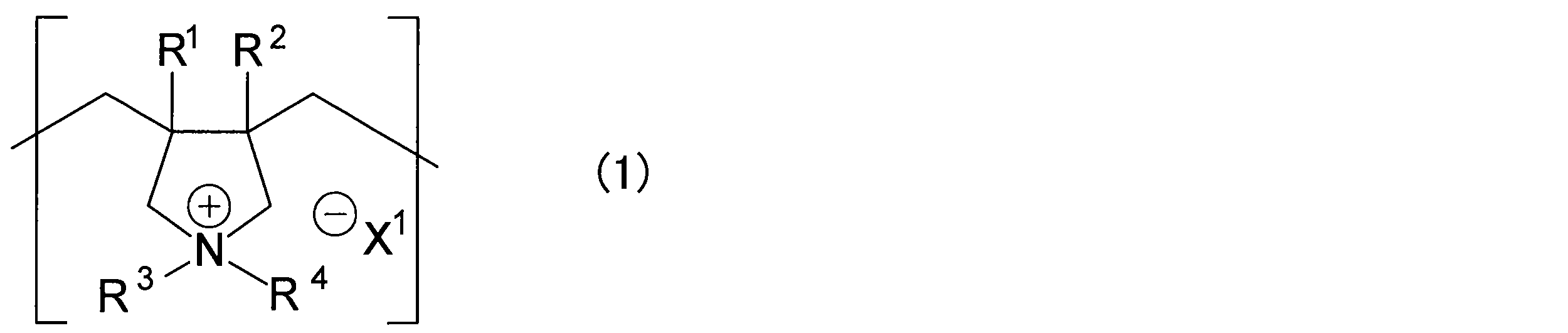
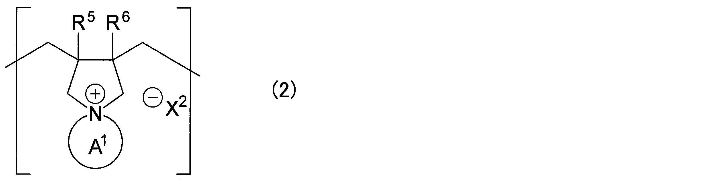
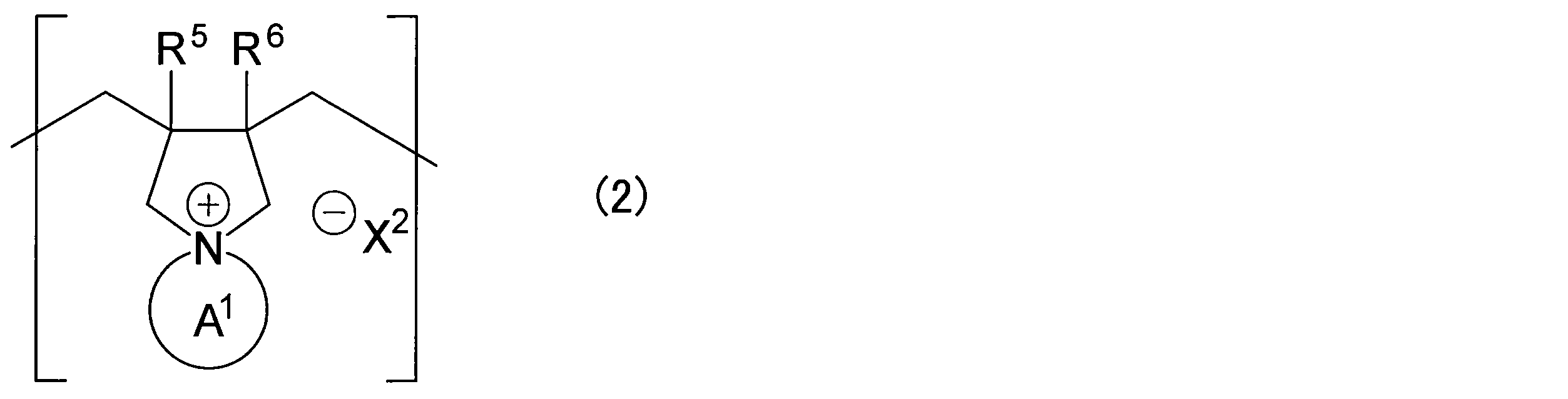
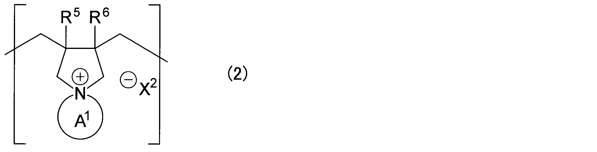
- an anion exchange electrolyte membrane having a polymer substrate containing a polar group and a graft chain containing a structural unit represented by the following formula (1) or the following formula (2) is provided.
- R 1 to R 6 each independently represent a hydrogen atom or an alkyl group having 1 to 8 carbon atoms
- Structure A 1 which is bonded to a nitrogen atom to form a ring structure with the nitrogen atom, is a structure in which a saturated carbon chain having 3 to 7 carbon atoms or a part of the carbon contained in the saturated carbon chain is substituted with a heteroatom.
- X 1 and X 2 are independently of each other a halide ion, a hydroxide ion or an anion of an organic acid or an inorganic acid.
- the present invention provides: An MEA for an anion exchange fuel cell comprising the anion exchange electrolyte membrane of the present invention is provided.
- the present invention provides: An anion exchange fuel cell comprising the MEA for an anion exchange fuel cell of the present invention is provided.
- an anion exchange type electrolyte membrane having good alkali resistance can be obtained.
- An MEA utilizing the excellent characteristics of the anion exchange electrolyte membrane can be obtained.
- an anion exchange fuel cell utilizing the excellent characteristics of the MEA can be obtained.
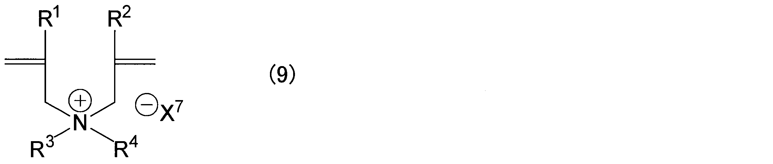
- graft monomer (M) the polymerizable monomer represented by the formula (9) or the formula (10) may be referred to as “graft monomer (M)”.
- R 1 to R 6 are each independently a hydrogen atom or an alkyl group having 1 to 8 carbon atoms.
- R 1 , R 2 , R 5 and R 6 are preferably each independently a hydrogen atom or an alkyl group having 1 to 4 carbon atoms.
- R 3 and R 4 are preferably each independently an alkyl group having 1 to 4 carbon atoms.
- the structure A 1 that is bonded to a nitrogen atom to form a ring structure with the nitrogen atom is a structure in which a saturated carbon chain having 3 to 7 carbon atoms or a part of carbon contained in the saturated carbon chain is substituted with a heteroatom.
- the structure A 1 is preferably a structure in which a saturated carbon chain having 3 to 5 carbon atoms or a part of carbon contained in the saturated carbon chain is substituted with a hetero atom.
- the hetero atom include a nitrogen atom and an oxygen atom.
- the counter anion is generally used by ion exchange. Therefore, X 7 and X 8 are not particularly limited unless ion exchange is difficult, and known counter anions can be used.
- X 7 and X 8 are, independently of one another, halide ions, hydroxide ions, or anions of organic or inorganic acids. Since the counter anion is used in the form of hydroxide ions, X 7 and X 8 are preferably hydroxide ions. From the viewpoint of storage stability of the anion exchange group, X 7 and X 8 are preferably halide ions, organic acid or inorganic acid anions. Examples of halide ions include fluoride ions, chloride ions, bromide ions, and iodide ions.
- the halide ions are preferably fluoride ions, chloride ions or bromide ions.
- anion of the organic acid a bistrifluoromethanesulfonimide anion, a thiocyanate anion, and a tetrakis [3,5-bis (trifluoromethyl) phenyl] borate anion are preferable.
- anion of the inorganic acid carbonate ion, hydrogen carbonate ion, tetrafluoroborate anion or hexafluorophosphate anion is preferable.
- electrolyte membranes used in fuel cells and the like often use a fluorine-containing substrate such as polytetrafluoroethylene or a polyolefin-based substrate such as polyethylene as the substrate.
- pores of a microporous polymer substrate such as a polyolefin resin are filled with an electrolyte polymer formed from the polymerizable monomer.
- an organic solvent having permeability to a substrate and hydrophilicity is used as an introduction agent for a polymerizable monomer.
- the electrolyte membrane obtained by using this method the electrolyte polymer is only filled in the pores of the base material and is not bonded to the base material. Therefore, the electrolyte polymer may elute from the pores during long-term operation.
- the polymer substrate included in the anion exchange electrolyte membrane includes a polar group.
- the polar group of the polymer substrate is preferably at least one functional group selected from the group consisting of a hydroxyl group, a carboxyl group, an ester group, an ether group, an amide group and an amino group, and has good alkali resistance and is colored. It is more preferable that it is a hydroxyl group from the point which is hard to carry out.
- These polar groups may be those introduced into the polymer substrate by performing a polar group introduction treatment.
- a commonly used technique such as corona treatment, plasma treatment, or UV treatment may be used.
- a method for introducing a polar group a method for introducing a polar group or a polymer having a polar group by a reaction with a radical formed by irradiation with radiation such as an electron beam may be used.
- the resin contained in the polymer substrate a known resin can be used as long as it is a resin that is insoluble in water and stable in an alkaline atmosphere without impairing the effects of the invention.
- the resin contained in the polymer substrate include polycarbonate resin; polyester resin such as polyethylene terephthalate; cellulosic resin such as cellophane; polyvinyl acetal resin such as polyvinyl formal and polyvinyl butyral; polyamide resin such as nylon; (meth) acrylic resin Urea resin; phenol resin; melamine resin; epoxy resin; acetal resin (polyacetal); polyvinyl acetate resin; polyvinyl alcohol resin; ethylene-vinyl alcohol copolymer; polyolefin resin that has been hydrophilized; Polystyrene resin.
- the polyolefin resin subjected to the hydrophilic treatment and the polystyrene resin subjected to the hydrophilic treatment may be a polyolefin resin or a polystyrene resin into which a polar group has been introduced by the hydrophilic treatment, and the polar group is, for example, a hydroxyl group.
- the resin contained in the polymer substrate it is preferable to use a polyvinyl alcohol resin, an ethylene-vinyl alcohol copolymer, or a polyolefin resin subjected to a hydrophilic treatment.
- the resin contained in the polymer substrate may be cross-linked from the viewpoint of suppressing the swelling of the anion exchange electrolyte membrane.
- the crosslinking method is not particularly limited as long as the introduction of the graft chain is not inhibited and the swelling of the polymer substrate can be suppressed, and a known method can be used.
- Examples of the cross-linking method include chemical cross-linking using a cross-linking agent and radiation cross-linking using radicals formed by irradiation with radiation. Either method may be used or a plurality of methods may be used in combination. .
- a polymer substrate having appropriate hydrophilicity it is preferable to use a polymer substrate having appropriate hydrophilicity.
- the polymer substrate preferably has a moisture content exceeding 0.1%.
- the water content of the polymer substrate is more preferably in the range of more than 0.1% and 100% or less, further preferably in the range of 1% to 80%, and more preferably in the range of 2% to 60%. More preferably, it is in the range of 4% to 40%, particularly preferably in the range of 5% to 20%.
- the graft monomer (M) can be easily introduced, and the graft chain can be easily introduced. If the water content of the polymer substrate is too low, it may be difficult to introduce the graft chain. If the water content of the polymer substrate becomes too high, the mechanical properties of the resulting anion exchange electrolyte membrane may be reduced.
- the moisture content is the ratio of the weight difference between the weight of the polymer substrate at the time of moisture content and the weight of the polymer substrate at the time of drying to the weight of the polymer substrate at the time of drying.
- the weight of the polymer base material at the time of drying is a value obtained by weighing the weight of the polymer base material when the polymer base material is allowed to stand for 2 hours or more in an atmosphere of 60 ° C. and dried.
- the weight of the polymer substrate is a value obtained by weighing the polymer substrate after maintaining the state in which the polymer substrate at the time of drying is immersed in water kept at 30 ° C. for 2 hours or more. When the polymer substrate is left to stand in an atmosphere of 60 ° C.
- the state in which the weight change of the polymer substrate does not occur is, for example, a weight W t obtained by allowing the polymer substrate to stand in a 60 ° C. atmosphere for a predetermined time (t time) of 2 hours or more and drying, Furthermore, it means that the weight difference from the weight W t +0.5 left to stand for 30 minutes (t + 0.5 hours) and dried is in the range of ⁇ 0.5% of W t . Maintaining the state in which the polymer substrate is immersed in water kept at 30 ° C. for 2 hours or more means that the polymer substrate does not change in weight based on the same criteria as described above.
- polymer base material one containing the above-described resin as the resin contained in the polymer substrate can be used.
- the ethylene content in the copolymer is preferably 1 to 99 mol%, more preferably 20 to 50 mol%. If the ethylene content is too low, the resulting anion exchange electrolyte membrane may be easily dissolved in water, and if it is too high, it may be difficult to introduce the graft monomer (M).
- the degree of saponification is preferably 70 mol% or more, and more preferably 98 mol% or more. If the degree of saponification is too small, the resulting anion exchange electrolyte membrane may be easily dissolved in water.
- the thickness of the polymer substrate is not particularly limited, but is, for example, in the range of 5 to 250 ⁇ m. From the viewpoint of film strength, the thickness of the polymer substrate is preferably in the range of 15 to 150 ⁇ m.
- an anion-exchange electrolyte membrane that has good membrane resistance, hardly breaks the membrane, has high strength, and is unlikely to cause membrane defects such as pinholes. Can be obtained.
- an inorganic base for example, potassium hydroxide
- the anion exchange type electrolyte membrane of this embodiment has a graft chain containing a structural unit represented by the formula (1) or the formula (2).
- the structure represented by the formula (1) is a structure derived from the monomer represented by the formula (9), and the structure represented by the formula (2) is a structure derived from the monomer represented by the formula (10).
- X 1 and X 2 are not particularly limited unless ion exchange is difficult, and known counter anions can be used.
- X 1 and X 2 are independently of each other halide ion, hydroxide ion or anion of organic acid or inorganic acid. Since the counter anion is used in the state of hydroxide ions, X 1 and X 2 are preferably hydroxide ions. From the viewpoint of the storage stability of the anion exchange group, X 1 and X 2 are preferably halide ions or organic acid anions. Examples of halide ions include fluoride ions, chloride ions, bromide ions, and iodide ions.
- the halide ions are preferably fluoride ions, chloride ions or bromide ions.
- anion of the organic acid a bistrifluoromethanesulfonimide anion, a thiocyanate anion, and a tetrakis [3,5-bis (trifluoromethyl) phenyl] borate anion are preferable.
- anion of the inorganic acid carbonate ion, hydrogen carbonate ion, tetrafluoroborate anion or hexafluorophosphate anion is preferable.
- Structure represented by the formula (1) or Formula (2) differs from the benzyl trialkyl ammonium, it does not have a benzylic position under alkaline atmosphere OH - nucleophilic substitution reaction is unlikely to occur by. Furthermore, in the structure represented by formula (1) or formula (2), since the nitrogen atom is included in the ring structure, the elimination reaction (E2) starting from the hydrogen atom present at the ⁇ -position when viewed from the nitrogen atom. Type reaction) hardly occurs. Therefore, the alkali resistance of the anion exchange group having the structure represented by the formula (1) or (2) is good, and the quaternary ammonium group is hardly deteriorated even under a high temperature atmosphere as compared with the benzyltrialkylammonium structure. .
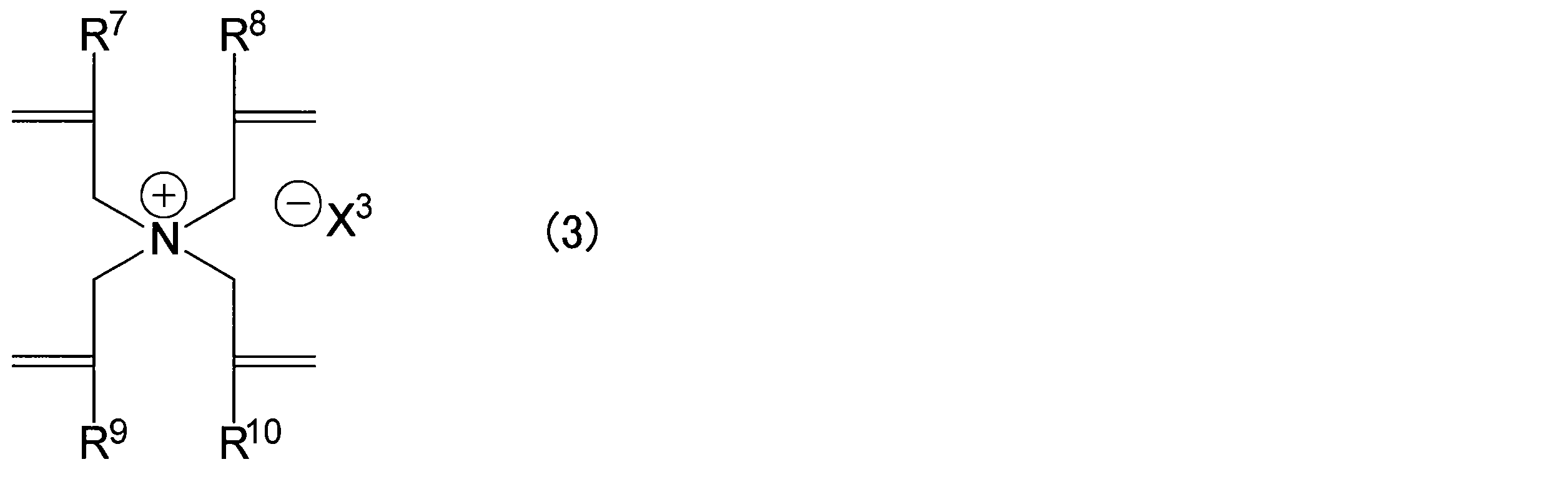
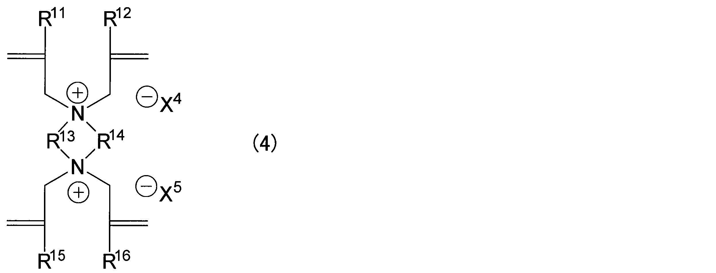
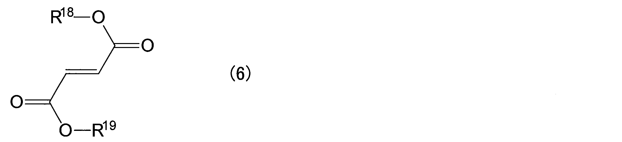
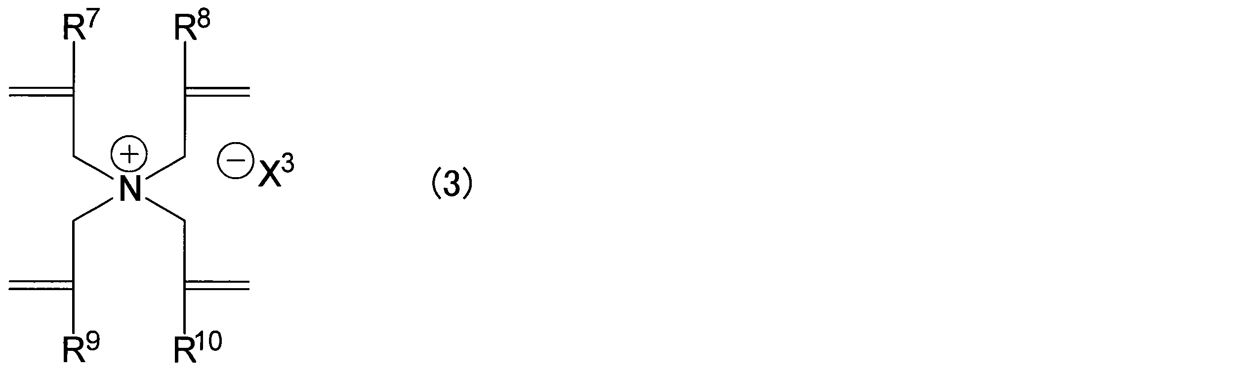
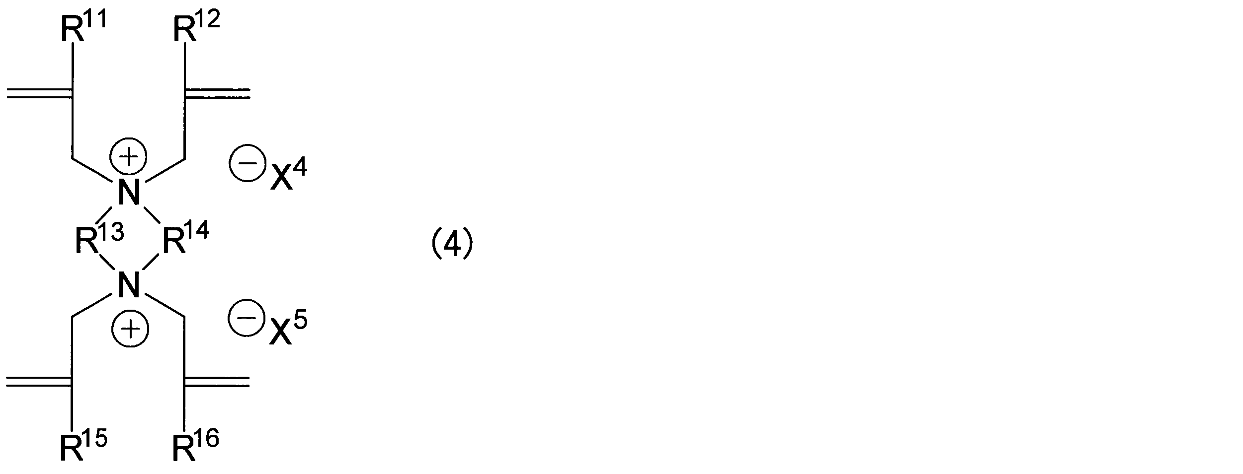
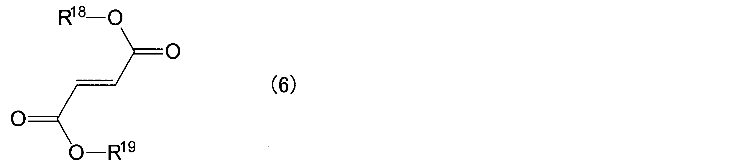
- the graft chain may further have a structure derived from a monomer (graft comonomer) represented by the following formula (3) to the following formula (7).
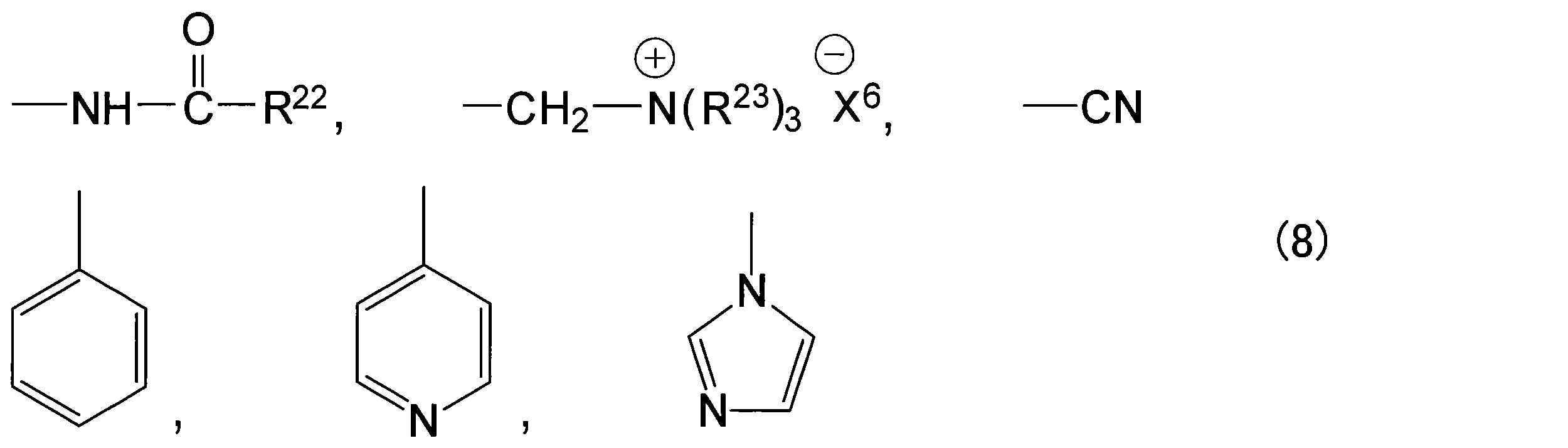
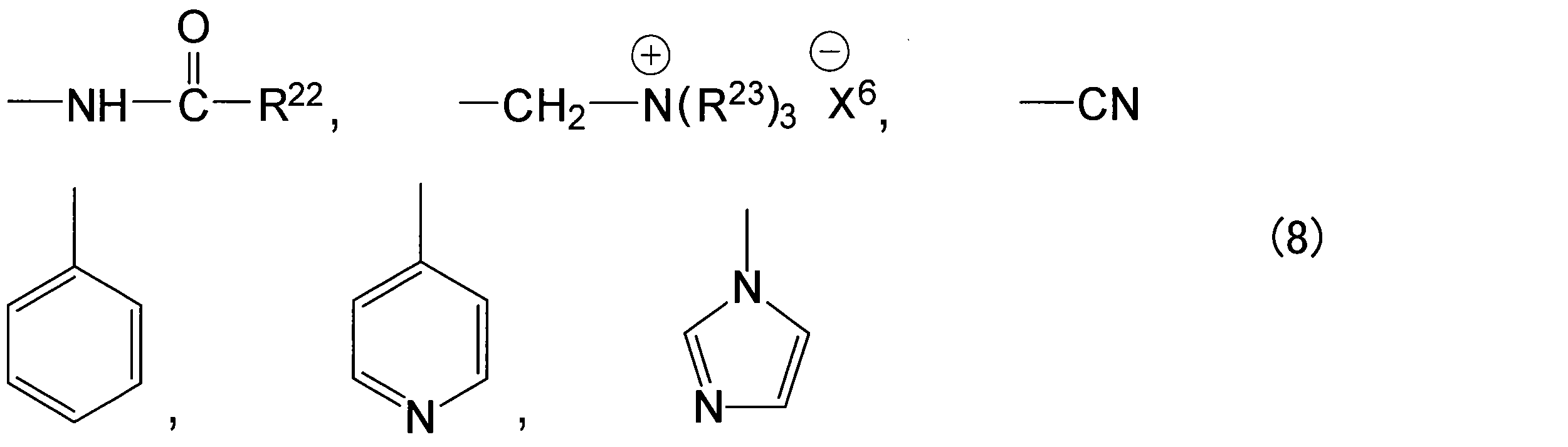
- Y is any structure represented by the following formula (8).
- R 7 to R 12 and R 15 to R 23 each independently represent a hydrogen atom or an alkyl group having 1 to 8 carbon atoms.
- R 7 to R 12 , R 15 and R 16 are preferably each independently a hydrogen atom or an alkyl group having 1 to 4 carbon atoms.
- R 13 and R 14 each independently represent an alkyl group having 1 to 3 carbon atoms, and the total value of the carbon number of R 13 and the carbon number of R 14 is in the range of 2 to 6.
- R 17 to R 23 are preferably each independently a hydrogen atom or an alkyl group having 1 to 4 carbon atoms.
- X 3 to X 6 are each independently a halide ion, a hydroxide ion, or an anion of an organic acid or an inorganic acid.
- the graft chain further includes a structure derived from the graft comonomer represented by the formula (3) or the formula (4), it becomes easy to introduce a crosslinked structure into the graft chain. As a result, it can contribute to improvement of alkali resistance and heat resistance of the obtained anion exchange type electrolyte membrane.
- the graft chain includes a structure derived from these graft comonomers, the permeability of the formed anion exchange electrolyte membrane may be controlled.
- the graft rate of the anion exchange electrolyte membrane is preferably in the range of 5 to 200%, for example. By improving the graft ratio, the ionic conductivity of the resulting anion exchange electrolyte membrane can be improved.
- This production method preferably includes a step of introducing a graft chain formed by polymerizing a polymerizable monomer into a polymer substrate.
- the graft chain is preferably formed by graft polymerization of a polymerizable monomer on a polymer substrate. Graft polymerization can be carried out, for example, by bringing a polymer substrate into contact with a polymerizable monomer.
- a polymerizable monomer contains the monomer (graft monomer (M)) shown by Formula (9) or Formula (10). Since the graft monomer (M) has been described above, redundant description is omitted. As the carbon number of R 1 to R 6 increases, the polarity of the graft monomer (M) decreases. As a result, the affinity between the polymer substrate and the graft monomer (M) increases, and the formation of graft chains tends to be facilitated. On the other hand, from the viewpoint of polymerizability of the graft monomer (M) and the number of anion exchange groups contained in the anion exchange electrolyte membrane per unit weight, it is preferable that R 1 to R 6 have a small number of carbon atoms. .
- graft monomer examples include diallyldimethylammonium chloride (DADMAC), diallyldimethylammonium bistrifluoromethanesulfonimide (DADMA-TFSI), and tetraallylammonium chloride (TAAC).
- DADMAC diallyldimethylammonium chloride
- DADMA-TFSI diallyldimethylammonium bistrifluoromethanesulfonimide
- TAAC tetraallylammonium chloride
- the step of adding an anion exchange group can be omitted in this embodiment.
- the polymerizable monomer may contain at least one monomer (graft comonomer) selected from the group consisting of formulas (3) to (7) together with the graft monomer (M). Since the expressions (3) to (7) have been described above, redundant description is omitted.
- the preferable content of the graft comonomer represented by the formula (3) or the formula (4) varies depending on the structure of the graft comonomer, the composition of the graft polymerization solution, the reaction temperature at which the graft polymerization is performed, and the use environment of the anion exchange type electrolyte membrane. For example, it is 0.1 to 1000 parts by weight, particularly 0.5 to 800 parts by weight with respect to 100 parts by weight of the graft monomer (M).
- the content of the graft comonomer represented by the formulas (5) to (7) depends on the structure of the graft monomer or the graft comonomer, the composition of the graft polymerization solution, the reaction temperature for carrying out the graft polymerization, and the use environment of the anion exchange type electrolyte membrane. Since it is different, it cannot be generally described, but for example, it is 1 to 5000 parts by weight, particularly 50 to 2000 parts by weight, with respect to 100 parts by weight of the graft monomer (M).
- the polymerizable monomer may be used for polymerization alone or may be prepared as a solution (polymerizable monomer solution) in which the polymerizable monomer is dissolved in a solvent.
- Examples of the solvent for dissolving the polymerizable monomer include water; alcohols such as methanol, ethanol or isopropanol; N, N-dimethylformamide (DMF), N, N-dimethylacetamide (DMAc), dimethyl sulfoxide (DMSO), Examples include aprotic polar solvents such as N-methylpyrrolidone (NMP).
- a solvent may be used independently and may use 2 or more types together.
- the concentration of the polymerizable monomer contained in the polymerizable monomer solution may be determined according to the polymerizability of the polymerizable monomer and the target graft ratio, and is, for example, 20% by weight or more. If the concentration of the polymerizable monomer is too low, the graft polymerization reaction may not proceed sufficiently.
- oxygen in the polymerizable monomer or polymerizable monomer solution is removed using a known method such as freeze degassing or bubbling using nitrogen gas or the like. It is preferable.
- the reaction time for carrying out the graft polymerization is, for example, 10 minutes to 12 hours.
- the reaction temperature for carrying out the graft polymerization is, for example, 0 to 90 ° C., particularly 40 to 80 ° C.
- the graft ratio can be controlled by these reaction temperature and reaction time.
- the manufacturing method suitable for manufacturing the anion exchange type electrolyte membrane of the present embodiment further includes a step of irradiating the polymer substrate with radiation. That is, it is preferable to include a step of irradiating the polymer substrate with radiation and a step of introducing a graft chain formed by polymerizing a polymerizable monomer onto the polymer substrate after irradiation.
- ionizing radiation such as ⁇ -rays, ⁇ -rays, ⁇ -rays, electron beams and ultraviolet rays may be used, and it is particularly preferable to use ⁇ -rays or electron beams.
- the irradiation dose is preferably in the range of 1 to 300 kGy, more preferably in the range of 10 to 100 kGy. If the irradiation dose is too small, the amount of radicals generated on the polymer substrate by irradiation with radiation may be reduced, and graft polymerization may be difficult. When the irradiation dose increases too much, the polymer base material may be decomposed by the irradiation of radiation, and many radicals may be generated by the irradiation of the radiation to cause an excessive polymerization reaction.
- a reaction in a solid-liquid two-phase system will be described as an example of a graft polymerization reaction having a step of irradiating radiation.
- the polymerizable monomer solution is placed in a glass or stainless steel container.
- vacuum degassing of the polymerizable monomer solution and bubbling using an inert gas such as nitrogen are performed.
- a polymer base material irradiated with radiation in advance is put into a polymerizable monomer solution to perform graft polymerization.
- the polymer substrate (graft polymer) into which the polymerizable monomer is polymerized and the graft chain is introduced is taken out of the solution.
- the obtained graft polymer is washed with the solvent 2 to 6 times and then dried.
- a solvent in which the polymerizable monomer and the polymer of the polymerizable monomer are easily dissolved and the polymer base material and the graft polymer are not dissolved may be used.
- acetone, methanol, ethanol, water, or the like can be used.
- the MEA of this embodiment includes the anion exchange electrolyte membrane of the present invention and a catalyst layer disposed on the surface of the anion exchange electrolyte membrane.
- FIG. 1 shows an example of an MEA using the anion exchange electrolyte membrane of the present invention.
- the MEA 1 shown in FIG. 1 includes an anion exchange electrolyte membrane 2, an anode electrode 3, and a cathode electrode 4.
- the anode electrode 3 is on one main surface of the anion exchange electrolyte membrane 2
- the cathode electrode 4 is an anion exchange electrolyte.
- the other main surface of the film 2 is disposed on each other.
- a catalyst layer provided in a known MEA used in an anion exchange fuel cell can be used.
- the catalyst does not necessarily need to be a noble metal such as platinum, and for example, a base metal such as nickel, cobalt, iron, silver or the like can be used.
- the structure of the catalyst layer, such as the specific catalyst contained, may be different or the same on the anode side (anode catalyst layer) and cathode side (cathode catalyst layer) of the MEA.
- the anion exchange fuel cell of this embodiment includes an MEA having the anion exchange electrolyte membrane of the present invention.
- FIG. 2 an example of the principal part of the anion exchange type fuel cell of this embodiment is shown.
- An anion exchange type fuel cell 11 shown in FIG. 2 is arranged so as to sandwich a pair of electrodes (anode electrode 3 and cathode electrode 4) disposed so as to sandwich the anion exchange type electrolyte membrane.
- a pair of separators anode separator 5 and cathode separator 6
- each member is joined in a state where pressure is applied in a direction perpendicular to the main surface of the member.
- the anion exchange type electrolyte membrane 2 and the electrodes 3 and 4 constitute an MEA.
- fuel is supplied to the anode side and oxidant is supplied to the cathode side.
- the fuel is, for example, an alkaline fuel containing alcohols, hydrazine (hydrate), etc., and has high reactivity and does not generate carbon dioxide on the principle of power generation. Therefore, a fuel containing hydrazine (hydrate) is preferable.
- the oxidizing agent is, for example, oxygen in the air.
- an inorganic base such as potassium hydroxide may be added to the fuel in order to improve the cell reaction activity or suppress poisoning due to carbon dioxide or the like.
- the anion exchange fuel cell of this embodiment has good alkali resistance, and even when the fuel cell is operated at a high temperature, the performance of the fuel cell is deteriorated due to the deterioration of the anion exchange electrolyte membrane. Hard to do.
- the anion exchange fuel cell of the present embodiment can include a known member as a member constituting the anion exchange fuel cell, in addition to the MEA of the present invention.
- the member includes, for example, a gas diffusion layer and a separator when the fuel cell is a single cell, a fuel supply device, an oxidant supply device, a humidifier, a current collector plate, and a temperature at which the power generation status is detected when the fuel cell is viewed as a system. Sensors, oxygen sensors, flow meters, humidity sensors, etc.
- room temperature is 23 ° C.
- DADMAC diallyldimethylammonium chloride CMS: 4-chloromethylstyrene EVOH: ethylene-vinyl alcohol copolymer EVOH (44): ethylene-vinyl alcohol copolymer (containing 44 mol% of ethylene units) EVOH (32): ethylene-vinyl alcohol copolymer (containing 32 mol% of ethylene units)
- PVA polyvinyl alcohol (saponification degree 98 mol%)
- UHMWPE Ultra high molecular weight polyethylene
- the polymer substrate was allowed to stand for 2 hours or more in a dryer at 60 ° C., dried until no change in weight occurred, and then cooled in a desiccator.
- the weight of the polymer base material at the time of drying was determined by weighing the polymer base material after cooling out from the desiccator. After maintaining the state in which the above-mentioned polymer base material weighed at the time of drying was immersed in water kept at 30 ° C. for 2 hours or more until no change in the weight of the polymer base material occurred, the polymer base material was taken out from the water. .
- the moisture content is the ratio of the weight difference between the weight of the polymer substrate at the time of moisture content and the weight of the polymer substrate at the time of drying to the weight of the polymer substrate at the time of drying.
- the anion exchange electrolyte membrane was immersed in 3 mol / L (23 ° C.) saline for 10 hours or more to convert the counter anion of the anion exchange electrolyte membrane into chloride ions. Thereafter, this anion exchange type electrolyte membrane was immersed in a 1 mol / L sodium nitrate (NaNO 3 ) aqueous solution for 12 hours or more. The liberated chloride ions were titrated with a 0.05 mol / L silver nitrate (AgNO 3 ) aqueous solution, and the ion exchange capacity was measured.
- W 0 is the weight (g) of the polymer base material before graft polymerization in the dry state
- W 1 is the weight (g) of the graft polymer after graft polymerization in the dry state.
- the “weight in the dry state” is a value in a state where the weight change is eliminated after standing for 2 hours or more in an atmosphere of 60 ° C.
- Example 1 EVOH (44) was used as the polymer substrate, and the polymer substrate was irradiated with an electron beam of 90 kGy at room temperature under vacuum. This polymer substrate was stored in an atmosphere of ⁇ 60 ° C. and cut into a square shape with a side length of 5 cm before the graft polymerization. An aqueous solution containing 60% by weight of DADMAC as the graft monomer (M) was prepared. Oxygen in the aqueous solution was removed using nitrogen gas. EVOH (44) irradiated with an electron beam was immersed in this aqueous solution, and the temperature of the aqueous solution (graft polymerization temperature) was maintained at 70 ° C.
- Example 2 A graft membrane was obtained in the same manner as in Example 1 except that EVOH (32) was used as the polymer substrate.
- the graft ratio of the obtained graft membrane (EVOH (32) -g-DADMAC) was 36%.
- Example 3 A graft membrane was obtained in the same manner as in Example 2 except that the polymerization time for graft polymerization was changed to 6 hours.
- the graft ratio of the obtained graft membrane (EVOH (32) -g-DADMAC) was 43%.
- Example 4 The polymer substrate EVOH (44) irradiated with an electron beam of 90 kGy was cut into a rectangle having a short side of 9.5 cm and a long side of 20 cm. A graft membrane was obtained in the same manner as in Example 1 except that this polymer substrate was used and the polymerization temperature was changed to 60 ° C. The graft ratio of the obtained graft membrane (EVOH (44) -g-DADMAC) was 21%.
- Example 5 A graft membrane was obtained in the same manner as in Example 4 except that EVOH (32) was used as the polymer substrate.
- the graft ratio of the obtained graft membrane (EVOH (32) -g-DADMAC) was 34%.
- Example 6 The polymer substrate EVOH (44) irradiated with an electron beam of 90 kGy was cut into a rectangle having a short side of 8 cm and a long side of 10 cm. A graft membrane was obtained in the same manner as in Example 1 except that this polymer substrate was used and the polymerization temperature was 50 ° C. The graft ratio of the obtained graft membrane (EVOH (44) -g-DADMAC) was 18%.
- Example 7 A graft membrane was obtained in the same manner as in Example 6 except that EVOH (32) was used as the polymer substrate.
- the graft ratio of the obtained graft membrane (EVOH (32) -g-DADMAC) was 28%.
- Example 8 A graft membrane was obtained in the same manner as in Example 1 except that PVA was used as the polymer substrate and the polymerization time was 3 hours.
- the graft ratio of the obtained graft membrane (PVA-g-DADMAC) was 25%.
- aqueous solution containing 60% by weight of DADMAC (monomer) was prepared, and oxygen in this aqueous solution was removed using nitrogen gas.
- UHMWPE irradiated with an electron beam was immersed in this aqueous solution, and the temperature of the aqueous solution (graft polymerization temperature) was maintained at 70 ° C. for 5 hours to perform graft polymerization. Thereafter, the membrane after graft polymerization was taken out. The process of impregnating with water for 1 hour or more and washing was repeated several times. The washed membrane was placed in a drying oven and dried at 60 ° C. for 2 hours or more. The graft ratio of the obtained film was 0%.
- Comparative Example 2 The same procedure as in Comparative Example 1 was conducted except that CMS (purity 100%) was used as a monomer and the polymerization time was 0.5 hours. The graft ratio of the obtained graft membrane was 96%.
- Table 1 shows the graft polymerization conditions and graft ratio
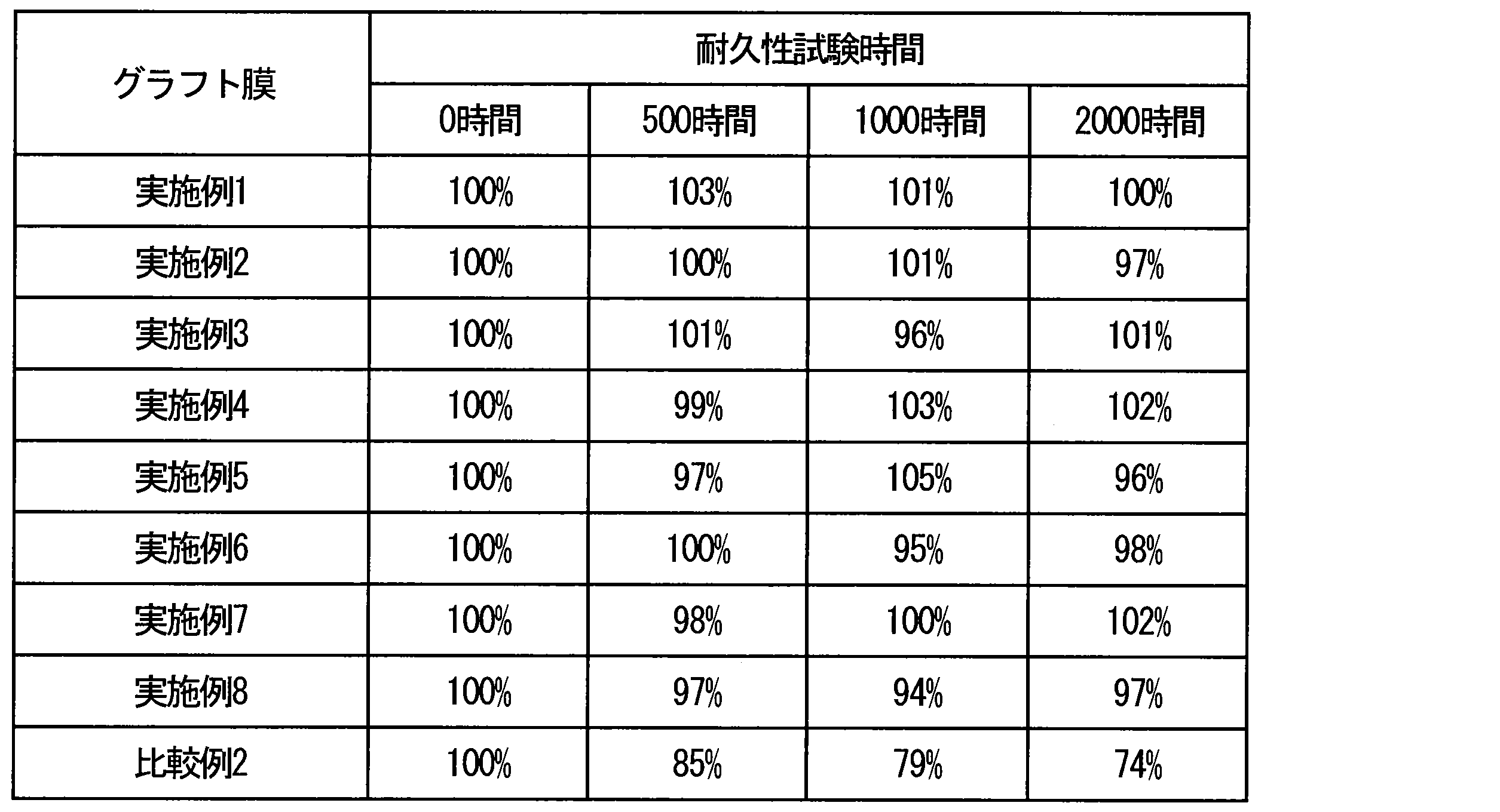
- Table 2 summarizes the results of the durability test of the obtained electrolyte membrane.
Landscapes
- Chemical & Material Sciences (AREA)
- Chemical Kinetics & Catalysis (AREA)
- Manufacturing & Machinery (AREA)
- Engineering & Computer Science (AREA)
- General Chemical & Material Sciences (AREA)
- Sustainable Development (AREA)
- Organic Chemistry (AREA)
- Life Sciences & Earth Sciences (AREA)
- Sustainable Energy (AREA)
- Electrochemistry (AREA)
- Medicinal Chemistry (AREA)
- Polymers & Plastics (AREA)
- Health & Medical Sciences (AREA)
- Materials Engineering (AREA)
- Physics & Mathematics (AREA)
- Spectroscopy & Molecular Physics (AREA)
- Crystallography & Structural Chemistry (AREA)
- Inorganic Chemistry (AREA)
- Fuel Cell (AREA)
- Manufacture Of Macromolecular Shaped Articles (AREA)
- Conductive Materials (AREA)
- Graft Or Block Polymers (AREA)
Abstract
Description
極性基を含む高分子基体と、下記式(1)又は下記式(2)により示される構成単位を含むグラフト鎖とを有する、アニオン交換形電解質膜、を提供する。
窒素原子に結合して窒素原子とともに環構造を形成する構造A1は、炭素数3~7の飽和炭素鎖又は前記飽和炭素鎖に含まれる炭素の一部がヘテロ原子で置換された構造であり、
X1及びX2は、互いに独立して、ハロゲン化物イオン、水酸化物イオン又は有機酸若しくは無機酸のアニオンである。
本発明のアニオン交換形電解質膜を備えたアニオン交換形燃料電池用のMEA、を提供する。
本発明のアニオン交換形燃料電池用のMEAを備えたアニオン交換形燃料電池、を提供する。

一般的に、燃料電池等に使用される電解質膜には、基材としてポリテトラフルオロエチレン等の含フッ素系の基材又はポリエチレン等のポリオレフィン系の基材が用いられることが多い。



X3~X6は、互いに独立して、ハロゲン化物イオン、水酸化物イオン又は有機酸若しくは無機酸のアニオンである。
本実施形態のMEAは、本発明のアニオン交換形電解質膜と、アニオン交換形電解質膜の表面に配置された触媒層とを備えている。
本実施形態のアニオン交換形燃料電池は、本発明のアニオン交換形電解質膜を有するMEAを備える。図2に、本実施形態のアニオン交換形燃料電池の要部の一例を示す。図2に示すアニオン交換形燃料電池11は、アニオン交換形電解質膜を挟持するように配置された一対の電極(アノード電極3及びカソード電極4)と、上記一対の電極を挟持するように配置された一対のセパレータ(アノードセパレータ5及びカソードセパレータ6)とを備え、各部材は、当該部材の主面に垂直な方向に圧力が印加された状態で接合されている。アニオン交換形電解質膜2と電極3、4は、MEAを構成している。
DADMAC:ジアリルジメチルアンモニウムクロリド
CMS:4-クロロメチルスチレン
EVOH:エチレン-ビニルアルコール共重合体
EVOH(44):エチレン-ビニルアルコール共重合体(エチレンユニット44mol%含有)
EVOH(32):エチレン-ビニルアルコール共重合体(エチレンユニット32mol%含有)
PVA:ポリビニルアルコール(ケン化度98mol%)
UHMWPE:超高分子量ポリエチレン
高分子基材を、60℃の乾燥機中にて2時間以上静置し、重量変化が生じなくなるまで乾燥させた後、デシケーター内で冷却した。冷却後の高分子基材をデシケーターから出してすぐに秤量した値を、乾燥時の高分子基材の重量とした。乾燥時の重量を秤量した上記の高分子基材を、30℃に保温した水中に浸漬させた状態を、高分子基材の重量変化が生じなくなるまで2時間以上維持した後、水中から取り出した。水中から取り出した高分子基材の表面に付着した余剰な水を濾紙等で拭き取ってから、高分子基材の重量を秤量した(含水時の高分子基材の重量)。含水率は、乾燥時の高分子基材の重量に対する、含水時の高分子基材の重量と乾燥時の高分子基材の重量との重量差の比率である。
アニオン交換形電解質膜を、3mol/L(23℃)の食塩水に10時間以上浸漬し、アニオン交換形電解質膜の対アニオンを塩化物イオンへ変換した。その後、このアニオン交換形電解質膜を、1mol/Lの硝酸ナトリウム(NaNO3)水溶液に12時間以上浸漬した。遊離してきた塩化物イオンを、0.05mol/Lの硝酸銀(AgNO3)水溶液を用いて滴定し、イオン交換容量を測定した。
予め用意した一辺の長さ5cmの正方形状のアニオン交換形電解質膜を、ポリテトラフルオロエチレン製容器に入れた1mol/Lの水酸化カリウム水溶液100mLに浸漬させ、80℃雰囲気下に静置した。所定の時間の経過後、膜を取り出し、純水を用いて複数回洗浄した後、イオン交換容量を測定した。このイオン交換容量を耐久性試験後のイオン交換容量とした。耐久性試験前のアニオン交換形電解質膜のイオン交換容量(イオン交換容量の初期値)に対する、耐久性試験後のイオン交換容量の比率を、耐久性試験の指標として用いた。
グラフト率は下式を用いて算出した。
グラフト率(%)=100×(W1-W0)/W0
ここで、W0は、乾燥状態におけるグラフト重合前の高分子基材の重量(g)、W1は、乾燥状態におけるグラフト重合後のグラフト重合体の重量(g)である。「乾燥状態における重量」とは、60℃雰囲気下2時間以上静置し、重量変化がなくなった状態の値を示す。
高分子基材としてEVOH(44)を用い、高分子基材に、室温、真空下で90kGyの電子線を照射した。この高分子基材を-60℃雰囲気下で保管し、グラフト重合の実施前に一辺の長さが5cmの正方形状に裁断した。
グラフトモノマー(M)であるDADMACを60重量%含む水溶液を用意した。この水溶液中の酸素を、窒素ガスを用いて除去した。この水溶液に、電子線を照射したEVOH(44)を浸漬させ、水溶液の温度(グラフト重合温度)を70℃に5時間維持し、グラフト重合を行った。その後グラフト重合後の膜を取り出した。水に1時間以上含浸させて洗浄する工程を数回繰り返した。洗浄後の膜を乾燥オーブンに入れて60℃雰囲気下で2時間以上乾燥させ、DADMACがグラフト重合されたEVOH(44)のグラフト膜を得た。得られたグラフト膜のグラフト率は20%であった。
高分子基材としてEVOH(32)を用いた以外は、実施例1と同様に行い、グラフト膜を得た。得られたグラフト膜(EVOH(32)-g-DADMAC)のグラフト率は36%であった。
グラフト重合の重合時間を6時間とした以外は、実施例2と同様に行い、グラフト膜を得た。得られたグラフト膜(EVOH(32)-g-DADMAC)のグラフト率は43%であった。
90kGyの電子線を照射した高分子基材EVOH(44)を、短辺9.5cm長辺20cmの矩形に裁断した。この高分子基材を用い、重合温度を60℃とした以外は、実施例1と同様に行い、グラフト膜を得た。得られたグラフト膜(EVOH(44)-g-DADMAC)のグラフト率は21%であった。
高分子基材としてEVOH(32)を用いた以外は、実施例4と同様に行い、グラフト膜を得た。得られたグラフト膜(EVOH(32)-g-DADMAC)のグラフト率は34%であった。
90kGyの電子線を照射した高分子基材EVOH(44)を、短辺8cm長辺10cmの矩形に裁断した。この高分子基材を用い、重合温度を50℃とした以外は、実施例1と同様に行い、グラフト膜を得た。得られたグラフト膜(EVOH(44)-g-DADMAC)のグラフト率は18%であった。
高分子基材としてEVOH(32)を用いた以外は、実施例6と同様に行い、グラフト膜を得た。得られたグラフト膜(EVOH(32)-g-DADMAC)のグラフト率は28%であった。
高分子基材としてPVAを用い、重合時間を3時間とした以外は、実施例1と同様に行い、グラフト膜を得た。得られたグラフト膜(PVA-g-DADMAC)のグラフト率は25%であった。
基材としてUHMWPEを用い、室温、真空下で90kGyの電子線を照射した。電子線照射後のUHMWPEを-60℃雰囲気下で保管し、グラフト重合の実施前に一辺の長さが5cmの正方形状に裁断した。
モノマーとしてCMS(純度100%)を用い、重合時間を0.5時間とした以外は、比較例1と同様に行った。得られたグラフト膜のグラフト率は96%であった。

Claims (6)
- 極性基を含む高分子基体と、下記式(1)又は下記式(2)により示される構成単位を含むグラフト鎖とを有する、アニオン交換形電解質膜。
ここで、R1~R6は、互いに独立して、水素原子又は炭素数1~8のアルキル基を示し、
窒素原子に結合して窒素原子とともに環構造を形成する構造A1は、炭素数3~7の飽和炭素鎖又は前記飽和炭素鎖に含まれる炭素の一部がヘテロ原子で置換された構造であり、
X1及びX2は、互いに独立して、ハロゲン化物イオン、水酸化物イオン又は有機酸若しくは無機酸のアニオンである。

- 前記グラフト鎖は、下記式(3)~下記式(7)のいずれか1つにより示されるモノマーに由来する構造をさらに有する、
請求項1に記載のアニオン交換形電解質膜。
ここで、R7~R12、R15~R21は、互いに独立して、水素原子又は炭素数1~8のアルキル基を示し、
R13及びR14は、互いに独立して、炭素数1~3のアルキル基を示し、
R13の炭素数とR14の炭素数との合計値は、2~6の範囲にあり、
X3~X6は、互いに独立して、ハロゲン化物イオン、水酸化物イオン又は有機酸若しくは無機酸のアニオンである。
ここで、Yは、下記式(8)により示されるいずれかの構造であり、
R22及びR23は、互いに独立して、水素原子又は炭素数1~8のアルキル基を示す。


- 前記極性基は、ヒドロキシル基、カルボキシル基、エステル基、エーテル基、アミド基及びアミノ基からなる群より選ばれる少なくとも1つである、
請求項1に記載のアニオン交換形電解質膜。 - 前記高分子基体は、ポリカーボネート樹脂、ポリエステル樹脂、セルロース系樹脂、ポリビニルアセタール樹脂、ポリアミド樹脂、(メタ)アクリル樹脂、ユリア樹脂、フェノール樹脂、メラミン樹脂、エポキシ樹脂、アセタール樹脂、ポリ酢酸ビニル樹脂、ポリビニルアルコール樹脂、エチレン-ビニルアルコール共重合体、親水化処理がなされたポリオレフィン樹脂及び親水化処理がなされたポリスチレン樹脂からなる群より選ばれる少なくとも1つを含む、
請求項1に記載のアニオン交換形電解質膜。 - 請求項1に記載のアニオン交換形電解質膜を備えたアニオン交換形燃料電池用の膜-電極接合体。
- 請求項5に記載のアニオン交換形燃料電池用の膜-電極接合体を備えたアニオン交換形燃料電池。
Priority Applications (5)
| Application Number | Priority Date | Filing Date | Title |
|---|---|---|---|
| CN201580024509.2A CN106463740B (zh) | 2014-06-13 | 2015-06-03 | 阴离子交换型电解质膜、具备该电解质膜的燃料电池用的膜-电极接合体以及燃料电池 |
| US15/306,621 US9692072B2 (en) | 2014-06-13 | 2015-06-03 | Anion exchange electrolyte membrane, membrane-electrode assembly for fuel cell including the same, and fuel cell including the same |
| EP15807127.4A EP3157085B1 (en) | 2014-06-13 | 2015-06-03 | Anion-exchange electrolyte membrane, membrane-electrode assembly for fuel cells provided with same, and fuel cell |
| JP2016527629A JP6064087B2 (ja) | 2014-06-13 | 2015-06-03 | アニオン交換形電解質膜、それを備えた燃料電池用の膜−電極接合体及び燃料電池 |
| KR1020177000679A KR20170020848A (ko) | 2014-06-13 | 2015-06-03 | 음이온 교환형 전해질막, 그것을 구비한 연료 전지용의 막-전극 접합체 및 연료 전지 |
Applications Claiming Priority (2)
| Application Number | Priority Date | Filing Date | Title |
|---|---|---|---|
| JP2014-122475 | 2014-06-13 | ||
| JP2014122475 | 2014-06-13 |
Publications (1)
| Publication Number | Publication Date |
|---|---|
| WO2015190075A1 true WO2015190075A1 (ja) | 2015-12-17 |
Family
ID=54833189
Family Applications (2)
| Application Number | Title | Priority Date | Filing Date |
|---|---|---|---|
| PCT/JP2015/002820 Ceased WO2015190075A1 (ja) | 2014-06-13 | 2015-06-03 | アニオン交換形電解質膜、それを備えた燃料電池用の膜-電極接合体及び燃料電池 |
| PCT/JP2015/002819 Ceased WO2015190074A1 (ja) | 2014-06-13 | 2015-06-03 | アニオン交換形電解質膜の製造方法及びその方法により得られたアニオン交換形電解質膜、それを備えた燃料電池用の膜-電極接合体及び燃料電池 |
Family Applications After (1)
| Application Number | Title | Priority Date | Filing Date |
|---|---|---|---|
| PCT/JP2015/002819 Ceased WO2015190074A1 (ja) | 2014-06-13 | 2015-06-03 | アニオン交換形電解質膜の製造方法及びその方法により得られたアニオン交換形電解質膜、それを備えた燃料電池用の膜-電極接合体及び燃料電池 |
Country Status (6)
| Country | Link |
|---|---|
| US (1) | US9692072B2 (ja) |
| EP (1) | EP3157085B1 (ja) |
| JP (1) | JP6064087B2 (ja) |
| KR (1) | KR20170020848A (ja) |
| CN (1) | CN106463740B (ja) |
| WO (2) | WO2015190075A1 (ja) |
Cited By (1)
| Publication number | Priority date | Publication date | Assignee | Title |
|---|---|---|---|---|
| JP2017222839A (ja) * | 2016-04-27 | 2017-12-21 | ライプニッツ−インスティチュート フュア ポリマーフォルシュング ドレスデン エーファウLeibniz−Institut fuer Polymerforschung Dresden e.V. | 水溶性アニオン交換体材料 |
Families Citing this family (4)
| Publication number | Priority date | Publication date | Assignee | Title |
|---|---|---|---|---|
| JP6687600B2 (ja) * | 2015-03-13 | 2020-04-22 | 日東電工株式会社 | アニオン交換基を有する樹脂、それを用いた樹脂含有液、積層体、部材、電気化学素子及び電気化学デバイス |
| JP6445226B1 (ja) * | 2017-06-15 | 2018-12-26 | 三菱エンジニアリングプラスチックス株式会社 | ポリアセタール樹脂組成物、成形品およびポリアセタール樹脂組成物の製造方法 |
| EP3990526A4 (en) | 2019-06-25 | 2023-07-05 | Council of Scientific & Industrial Research | Fluorinated-aliphatic hydrocarbon based stable anion- exchange membrane and its method of preparation thereof |
| KR102760152B1 (ko) * | 2023-03-14 | 2025-02-03 | 한국과학기술연구원 | 음이온 교환막 및 이의 제조방법 |
Citations (4)
| Publication number | Priority date | Publication date | Assignee | Title |
|---|---|---|---|---|
| JP2007335119A (ja) * | 2006-06-12 | 2007-12-27 | Nippon Shokubai Co Ltd | 固体電解質用材料 |
| JP2008204647A (ja) * | 2007-02-16 | 2008-09-04 | Nippon Synthetic Chem Ind Co Ltd:The | アニオン交換膜型燃料電池用の電解質膜および接着剤 |
| WO2010055889A1 (ja) * | 2008-11-14 | 2010-05-20 | 株式会社トクヤマ | 陰イオン交換膜及びその製造方法 |
| JP2013189595A (ja) * | 2012-03-15 | 2013-09-26 | Nitto Denko Corp | グラフト鎖を有する高分子電解質膜およびその製造方法 |
Family Cites Families (6)
| Publication number | Priority date | Publication date | Assignee | Title |
|---|---|---|---|---|
| US20070020501A1 (en) * | 2005-07-21 | 2007-01-25 | Ling-Feng Li | Polyelectrolyte membranes as separator for battery and fuel cell applications |
| GB0701449D0 (en) | 2007-01-26 | 2007-03-07 | Secr Defence | Anion Exchange Membranes |
| EP2247372A4 (en) * | 2007-12-27 | 2013-12-04 | 3M Innovative Properties Co | METHOD FOR MAKING A FUNCTIONALIZED MEMBRANE |
| CN102544547A (zh) * | 2012-01-06 | 2012-07-04 | 东华大学 | 具有耐碱稳定性的碱性阴离子交换复合膜及其制备和应用 |
| CN103358612B (zh) * | 2012-03-26 | 2016-10-19 | 中国科学院上海高等研究院 | 直接甲醇燃料电池用的阻醇膜及其制法 |
| CN103521276B (zh) * | 2013-10-12 | 2016-01-20 | 东华大学 | 一种碳纳米管掺杂型碱性阴离子交换复合膜及其制备方法和应用 |
-
2015
- 2015-06-03 JP JP2016527629A patent/JP6064087B2/ja not_active Expired - Fee Related
- 2015-06-03 CN CN201580024509.2A patent/CN106463740B/zh not_active Expired - Fee Related
- 2015-06-03 WO PCT/JP2015/002820 patent/WO2015190075A1/ja not_active Ceased
- 2015-06-03 WO PCT/JP2015/002819 patent/WO2015190074A1/ja not_active Ceased
- 2015-06-03 US US15/306,621 patent/US9692072B2/en not_active Expired - Fee Related
- 2015-06-03 EP EP15807127.4A patent/EP3157085B1/en active Active
- 2015-06-03 KR KR1020177000679A patent/KR20170020848A/ko not_active Withdrawn
Patent Citations (4)
| Publication number | Priority date | Publication date | Assignee | Title |
|---|---|---|---|---|
| JP2007335119A (ja) * | 2006-06-12 | 2007-12-27 | Nippon Shokubai Co Ltd | 固体電解質用材料 |
| JP2008204647A (ja) * | 2007-02-16 | 2008-09-04 | Nippon Synthetic Chem Ind Co Ltd:The | アニオン交換膜型燃料電池用の電解質膜および接着剤 |
| WO2010055889A1 (ja) * | 2008-11-14 | 2010-05-20 | 株式会社トクヤマ | 陰イオン交換膜及びその製造方法 |
| JP2013189595A (ja) * | 2012-03-15 | 2013-09-26 | Nitto Denko Corp | グラフト鎖を有する高分子電解質膜およびその製造方法 |
Cited By (2)
| Publication number | Priority date | Publication date | Assignee | Title |
|---|---|---|---|---|
| JP2017222839A (ja) * | 2016-04-27 | 2017-12-21 | ライプニッツ−インスティチュート フュア ポリマーフォルシュング ドレスデン エーファウLeibniz−Institut fuer Polymerforschung Dresden e.V. | 水溶性アニオン交換体材料 |
| JP7242160B2 (ja) | 2016-04-27 | 2023-03-20 | ライプニッツ-インスティチュート フュア ポリマーフォルシュング ドレスデン エーファウ | 水溶性アニオン交換体材料 |
Also Published As
| Publication number | Publication date |
|---|---|
| EP3157085B1 (en) | 2019-09-04 |
| CN106463740A (zh) | 2017-02-22 |
| EP3157085A4 (en) | 2017-11-15 |
| US20170047604A1 (en) | 2017-02-16 |
| JP6064087B2 (ja) | 2017-01-18 |
| EP3157085A1 (en) | 2017-04-19 |
| WO2015190074A1 (ja) | 2015-12-17 |
| CN106463740B (zh) | 2019-07-30 |
| JPWO2015190075A1 (ja) | 2017-04-20 |
| KR20170020848A (ko) | 2017-02-24 |
| US9692072B2 (en) | 2017-06-27 |
Similar Documents
| Publication | Publication Date | Title |
|---|---|---|
| US9731247B2 (en) | Ion exchange membranes | |
| US10637087B2 (en) | Electrolyte membrane, method for producing the same, and membrane-electrode assembly for fuel cells that includes electrolyte membrane | |
| JP6064087B2 (ja) | アニオン交換形電解質膜、それを備えた燃料電池用の膜−電極接合体及び燃料電池 | |
| US8372558B2 (en) | Highly proton-conductive polymer electrolyte membranes that excel in mechanical strength and a process for producing the same | |
| KR20130132107A (ko) | 이온 교환막 충전용 조성물, 이온 교환막의 제조방법, 이온 교환막 및 레독스 플로우 전지 | |
| Hwang et al. | Anisotropic radio-chemically pore-filled anion exchange membranes for solid alkaline fuel cell (SAFC) | |
| WO2015166650A1 (ja) | 低膨潤性のアニオン交換膜およびその製造方法ならびにそれを用いた燃料電池 | |
| JP6687600B2 (ja) | アニオン交換基を有する樹脂、それを用いた樹脂含有液、積層体、部材、電気化学素子及び電気化学デバイス | |
| JP2014084349A (ja) | アニオン伝導性高分子電解質膜およびその製造方法ならびにそれを用いた膜電極接合体および燃料電池 | |
| JP6375052B2 (ja) | アニオン交換膜、それを備えた電気化学素子及び電気化学デバイス | |
| WO2016002227A1 (ja) | 液体燃料電池用隔膜及びそれを備えた膜-電極接合体 | |
| JP2016015286A (ja) | 液体燃料電池用隔膜及びそれを備えた膜−電極接合体 | |
| JP2016015285A (ja) | アルカリ形液体燃料電池用隔膜及びそれを備えた膜−電極接合体 | |
| Arı et al. | The Effect of Cross-linking Technique on Membrane Performance for Direct Methanol Alkaline Fuel Cell Application | |
| JP2016015284A (ja) | アルカリ形液体燃料電池用隔膜及びそれを備えた膜−電極接合体 | |
| JP2016015287A (ja) | 液体燃料電池用隔膜及びそれを備えた膜−電極接合体 | |
| KR20070095313A (ko) | 전극에 대한 접착성이 우수한 전해질 막 |
Legal Events
| Date | Code | Title | Description |
|---|---|---|---|
| 121 | Ep: the epo has been informed by wipo that ep was designated in this application |
Ref document number: 15807127 Country of ref document: EP Kind code of ref document: A1 |
|
| ENP | Entry into the national phase |
Ref document number: 2016527629 Country of ref document: JP Kind code of ref document: A |
|
| WWE | Wipo information: entry into national phase |
Ref document number: 15306621 Country of ref document: US |
|
| NENP | Non-entry into the national phase |
Ref country code: DE |
|
| REEP | Request for entry into the european phase |
Ref document number: 2015807127 Country of ref document: EP |
|
| WWE | Wipo information: entry into national phase |
Ref document number: 2015807127 Country of ref document: EP |
|
| ENP | Entry into the national phase |
Ref document number: 20177000679 Country of ref document: KR Kind code of ref document: A |