WO2015190310A1 - 死角補助装置 - Google Patents
死角補助装置 Download PDFInfo
- Publication number
- WO2015190310A1 WO2015190310A1 PCT/JP2015/065493 JP2015065493W WO2015190310A1 WO 2015190310 A1 WO2015190310 A1 WO 2015190310A1 JP 2015065493 W JP2015065493 W JP 2015065493W WO 2015190310 A1 WO2015190310 A1 WO 2015190310A1
- Authority
- WO
- WIPO (PCT)
- Prior art keywords
- blind spot
- mirror
- image
- semi
- flat mirror
- Prior art date
- Legal status (The legal status is an assumption and is not a legal conclusion. Google has not performed a legal analysis and makes no representation as to the accuracy of the status listed.)
- Ceased
Links
Images


Classifications
-
- B—PERFORMING OPERATIONS; TRANSPORTING
- B60—VEHICLES IN GENERAL
- B60R—VEHICLES, VEHICLE FITTINGS, OR VEHICLE PARTS, NOT OTHERWISE PROVIDED FOR
- B60R1/00—Optical viewing arrangements; Real-time viewing arrangements for drivers or passengers using optical image capturing systems, e.g. cameras or video systems specially adapted for use in or on vehicles
- B60R1/02—Rear-view mirror arrangements
- B60R1/08—Rear-view mirror arrangements involving special optical features, e.g. avoiding blind spots, e.g. convex mirrors; Side-by-side associations of rear-view and other mirrors
- B60R1/081—Rear-view mirror arrangements involving special optical features, e.g. avoiding blind spots, e.g. convex mirrors; Side-by-side associations of rear-view and other mirrors avoiding blind spots, e.g. by using a side-by-side association of mirrors
- B60R1/082—Rear-view mirror arrangements involving special optical features, e.g. avoiding blind spots, e.g. convex mirrors; Side-by-side associations of rear-view and other mirrors avoiding blind spots, e.g. by using a side-by-side association of mirrors using a single wide field mirror or an association of rigidly connected mirrors
-
- B—PERFORMING OPERATIONS; TRANSPORTING
- B60—VEHICLES IN GENERAL
- B60R—VEHICLES, VEHICLE FITTINGS, OR VEHICLE PARTS, NOT OTHERWISE PROVIDED FOR
- B60R1/00—Optical viewing arrangements; Real-time viewing arrangements for drivers or passengers using optical image capturing systems, e.g. cameras or video systems specially adapted for use in or on vehicles
- B60R1/10—Front-view mirror arrangements; Periscope arrangements, i.e. optical devices using combinations of mirrors, lenses, prisms or the like ; Other mirror arrangements giving a view from above or under the vehicle
-
- G—PHYSICS
- G02—OPTICS
- G02B—OPTICAL ELEMENTS, SYSTEMS OR APPARATUS
- G02B7/00—Mountings, adjusting means, or light-tight connections, for optical elements
- G02B7/18—Mountings, adjusting means, or light-tight connections, for optical elements for prisms; for mirrors
- G02B7/182—Mountings, adjusting means, or light-tight connections, for optical elements for prisms; for mirrors for mirrors
- G02B7/1822—Mountings, adjusting means, or light-tight connections, for optical elements for prisms; for mirrors for mirrors comprising means for aligning the optical axis
- G02B7/1824—Manual alignment
- G02B7/1825—Manual alignment made by screws, e.g. for laser mirrors
Definitions
- the present invention relates to a blind spot assisting device that projects an image of a blind spot area obstructed by an obstacle such as a front pillar in a vehicle.
- a device disclosed in Patent Document 1 is known as a visual device that displays a blind spot caused by an obstacle such as a front pillar in a vehicle.
- the visual recognition device includes a first mirror that reflects the front of the vehicle and a second mirror that reflects light incident on the first mirror toward the driver, and an image that the driver can see through the direct visual recognition area that sandwiches the front pillar of the vehicle.
- the first mirror and / or the second mirror can be adjusted so that the images reflected on the second mirror are continuous.
- the present invention has been made in view of the above problems, and it is an object of the present invention to provide a blind spot assisting device that can more easily project an image of a blind spot area continuously with an image directly viewed by a viewer. To do.
- a blind spot assisting device is a blind spot assisting device that displays an image of a blind spot area obstructed by an obstacle in a vehicle, Arranged so that a semi-transmission mirror that receives light representing the image, is provided on the viewer side, reflects a part of the light, and transmits a part of the light, and a mirror that reflects the light to the semi-transmission mirror face each other.
- a pair of mirrors, The semi-transmission mirror is arranged in a state of being opened at a predetermined angle on the viewer side with respect to the mirror.
- FIG. 1 It is a figure which shows the general view of the driver's seat vicinity of the vehicle by which the blind spot auxiliary device which concerns on embodiment of this invention is arrange
- FIG. 1 is a diagram showing an overview of the vicinity of a driver's seat of a vehicle 1 in which a blind spot assisting device 100 according to the present embodiment is arranged.
- the vehicle 1 includes a steering 10, a windshield glass 20, side glasses 30 and 40, and front pillars 50 and 60.
- Reference numerals 21 and 22 denote light-shielding black ceramic (black ceramic) portions that are printed on the periphery of the windshield glass 20.
- a viewer In the vehicle 1, a viewer (mainly a driver) directly sees the scenery in the area where the windshield glass 20 (excluding the black ceramic portion 21) and the side glasses 30 and 40 are arranged, while the front pillar 50, In the area where 60 and the black sera parts 21 and 22 are arranged, the front pillars 50 and 60 and the black sera parts 21 and 22 block the visual field of the viewer, resulting in a blind spot area where the landscape cannot be seen directly. That is, the front pillars 50 and 60 and the black ceramic portions 21 and 22 correspond to obstacles in the present invention.
- FIGS. 2 and 3 are plan views showing an overview of the blind spot assisting device 100
- FIG. 4 is a perspective view showing the blind spot assisting device 100.
- FIG. 2 shows a state in which the viewer is seated in the driver's seat, and viewpoint 2 indicates the viewer's viewpoint (eye point).
- the blind spot assisting device 100 is disposed on the front pillar 50 on the right side (driver side) when viewed from the viewer side, and is a blind spot area A that is blocked by the front pillar 50 and the black ceramic portion 21.
- the image of The blind spot assisting device 100 is disposed so as to face the front pillar 50 and the black ceramic portion 21 when viewed from the viewer.
- the blind spot assisting device 100 includes a pair of plane mirrors (a pair of mirrors) 110 as shown in FIGS.
- the pair of flat mirrors 110 are arranged such that a semi-transmissive flat mirror (semi-transmissive mirror) 111 that reflects a part of the incident light L and transmits a part thereof and a flat mirror (mirror) 112 face each other. Consists of.
- the transflective flat mirror 111 and the flat mirror 112 are arranged in a case body (not shown) so that the transflective flat mirror 111 is closer to the viewpoint 2 (viewer) side than the flat mirror 112 as shown in FIG. It is fixed in a state of open by a predetermined angle theta M.
- the reason why the pair of plane mirrors 110 are not completely parallel to each other and are arranged in this manner will be described in detail later. Note that the pair of mirrors of the present invention may be curved mirrors instead of flat mirrors.
- the transflective flat mirror 111 is disposed on the viewer side, and by depositing a metal such as aluminum on the surface of a base material made of a translucent resin material such as polyethylene terephthalate, polycarbonate, polyethylene, acrylic, etc. A transflective layer having a reflectance is formed.
- the transflective flat mirror 111 may be formed by coating the surface of a base material with a dielectric multilayer film.
- the transflective flat mirror 111 has a base 111a facing the flat mirror 112 and an extending portion 111b extending from the base 111a.
- the transflective flat mirror 111 and the flat mirror 112 are stepped in the horizontal direction. Are arranged as follows.
- the plane mirror 112 is arranged so that the plane (reflection surface) faces the plane (semi-transmission reflection surface) of the semi-transmission plane mirror 111.
- the plane mirror 112 is made of a base material made of the above-described translucent resin material. It is a flat aluminum vapor deposition mirror formed by vapor-depositing a metal such as aluminum on the surface.
- the semi-transmissive flat mirror 111 and the flat mirror 112 are such that each plane (semi-transmissive reflective surface and reflective surface) has a width perpendicular to the traveling direction of the light L in the pair of flat mirrors 110. Is formed in a substantially wedge shape so as to gradually decrease in the traveling direction of the light L in the pair of flat mirrors 110. This is to reduce the size and weight by removing unnecessary portions that are out of the visual field range of the viewer. Further, the incident side end (incident side side) E1 of the semi-transmissive flat mirror 111 and the incident side end (incident side side) E2 of the flat mirror 112 are along the glass surface of the windshield glass 20. Is inclined. This is because the glass is disposed close to the glass surface of the windshield glass 20.
- a blind spot area A that is blocked by the front pillar 50 (including the black ceramic portion 21 (not shown)) is generated in the front view of the viewer (viewpoint 2). Therefore, the image M present in the blind spot area A cannot be directly viewed from the viewpoint 2.
- the light L from the image M is incident on the pair of plane mirrors 110 and is repeatedly reflected between the pair of plane mirrors 110, while a part of the light L is emitted from the pair of plane mirrors 110 (semi-transmissive plane). The light passes through the mirror 111). Note that light incident on the pair of plane mirrors 110 and repeatedly reflected between the pair of plane mirrors 110 is light having an inclination with respect to the plane of the pair of plane mirrors 110.
- the viewer places the blind spot assisting device 100 at an arbitrary height of the front pillar 50 (a height suitable for the viewpoint 2) and the pair of plane mirrors 110.
- the angle of the pair of plane mirrors 110 is adjusted so that the image of the blind spot area A appears in the image, that is, the light L from the blind spot area A reaches the viewpoint 2. Since the mutual positional relationship between the transflective flat mirror 111 and the flat mirror 112 is fixed, the pair of flat mirrors 110 can be arranged at the same time by one arrangement operation, and the pair of plane mirrors can be arranged at one adjustment operation. 110 angles can be adjusted simultaneously.
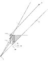
- FIG. 5 is a plan view showing a blind spot assisting device 100 according to the present embodiment
- FIG. 6 is a plan view showing a blind spot assisting device 101 as a comparative example.
- the blind spot assisting device 101 is arranged such that the semi-transmissive flat mirror 111 and the flat mirror 112 are parallel to each other, and has the same configuration as the blind spot assisting device 100 other than that.
- the exit side end (exit side) E3 of the plane mirror 112 is viewed from the viewpoint 2, the image of the blind spot area A reflected on the plane mirror 112 with the exit side end E3 as a boundary and the exit. Strictly speaking, there is a deviation between the front scenery directly visible on the right side of the side end E3.
- the interval W1 between the optical path C1 and the optical path C2 is constant regardless of the distance to the images M1 and M2, the smaller the distance from the viewpoint 2 to the images M1 and M2 (the larger the image to be visually recognized), the relative deviation.
- the image that the viewer should be aware of in the blind spot area A such as being on the road of the vehicle 1
- the image that the viewer should be aware of in the blind spot area A is about 10 m from the vehicle 1, and although the image of the blind spot area A can be projected, it is safe. From the standpoint of further improving the performance, the difference between the image reflected on the flat mirror 112 and the forward scenery directly visible cannot be ignored.
- the inventor of the present application has opened the semi-transmissive flat mirror 111 by the predetermined angle ⁇ M on the viewpoint 2 (viewer) side with respect to the flat mirror 112 in the blind spot assisting device 100 as described above. I came up with the arrangement. As shown in FIG. 5, when the transflective flat mirror 111 is arranged in a state opened to the viewpoint 2 side with respect to the flat mirror 112, the distance between the transflective flat mirror 111 and the flat mirror 112 is directed toward the traveling direction of the light L. The appearance gradually increases.
- the optical path C3 from the viewpoint 2 through the pair of plane mirrors 110 to the blind spot region A has an incident angle with respect to the reflecting surface of the plane mirror 112 as the first incident angle (first It changes so as to be gradually deeper than the angle at which it enters the exit-side end E3 of the plane mirror 112, and an arbitrary point on the transflective surface of the transflective plane mirror 111 (here, the entrance-side end E1). and the) semitransparent plane mirror 111 from emits inclined at an angle theta 1 only the front side with respect to the optical path C2 when it is parallel to the plane mirror 112.
- the optical path C3 intersects the optical path C1 passing through the emission side end E3 from the viewpoint 2 at an arbitrary image M1 (for example, a position about 10 m ahead of the vehicle 1) with respect to the plane mirror 112 of the semi-transmissive plane mirror 111.
- an arbitrary image M1 for example, a position about 10 m ahead of the vehicle 1
- the angle theta M a viewer it is possible to prevent displacement between the front scene to view directly the image reflected in a plane mirror 112 when viewing the image M1.
- the angle of the semi-transmissive flat mirror 111 with respect to the flat mirror 112 is ⁇ M ( ⁇ M > 0)
- the incident angle of the optical path C2 with respect to the flat mirror 112 is It changes by 2 ⁇ M from the incident angle.
- ⁇ 2 ⁇ 1
- the angle ⁇ 2 is defined as H at the intersection of the perpendicular p of the optical path C1 passing through the emission side end E1 of the transflective flat mirror 111 from which the optical path C3 is emitted and the optical path C1, and the intersection H of the emission side E1 and the intersection H. Is expressed by the following formula (2), where W2 is the interval (ie, the length of the perpendicular p) and D is the distance from the intersection H to the position of the image M1.
- the angle ⁇ M of the semi-transmission plane mirror 111 is actually 1 ° or less. becomes very small angle, the angle theta M may be managed by dimensioning of the holding portion of the case body which holds the semitransparent plane mirror 111 and plane mirror 112.
- the angle ⁇ M of the semi-transmissive flat mirror 111 is set, the difference between the image reflected on the flat mirror 112 and the directly forward-viewed landscape is that the position of the image reflected on the flat mirror 112 is different from the blind spot assisting device 100.
- the present invention is not limited to the above calculation, and a shift reduction effect can be obtained by a simple setting in which the transflective flat mirror 111 is simply opened to the viewpoint 2 side with respect to the flat mirror 112. .
- the blind spot assisting device 100 configured as described above is a blind spot assisting device 100 that projects an image of the blind spot area A that is obstructed by the obstacles (the front pillar 50 and the black ceramic portion 21), and is incident with light L representing the image.
- the semi-transmissive flat mirror 111 provided on the viewer side that reflects part of the light L and transmits part of the light L and the flat mirror 112 that reflects the light L to the semi-transmissive flat mirror 111 are arranged so as to face each other.
- the semi-transparent plane mirror 111 is arranged in a state where the plane mirror 112 is opened at a predetermined angle ⁇ M on the viewer side with respect to the plane mirror 112.
- the semi-transmissive flat mirror 111 is used for one of the pair of flat mirrors 110, the viewer can visually recognize the image and landscape of the image M reflected on the flat mirror 112 through the semi-transmissive flat mirror 111.
- the degree of freedom of the arrangement position of the plane mirror 110 is increased, and the image of the blind spot area A can be projected more easily and continuously with the image (landscape) that is directly viewed by the viewer.
- a camera that captures the blind spot area A and a display that displays the captured image are unnecessary, the cost is lower than when these are used.
- the transflective flat mirror 111 is arranged with a predetermined angle ⁇ M opened to the viewer side with respect to the flat mirror 112, so that the image reflected on the flat mirror 112 at the exit side end E3 of the flat mirror 112 can be obtained. It is possible to reduce the deviation from the front scenery that is directly visible.
- the blind spot assist device 100 differs from the embodiment described above in another embodiment, it is that it includes an angle adjustment mechanism 120 for adjusting the angle theta M of semitransparent plane mirror 111.
- the angle adjusting mechanism 120 includes an angle adjusting bolt 121 provided on the semi-transmissive reflective surface side of the semi-transmissive flat mirror 111 and an elastic member 122 provided on the viewer side of the semi-transmissive flat mirror 111.
- the angle adjusting bolt 121 is inserted into a female screw hole (not shown) formed in the case body and comes into contact with the semi-transmissive flat mirror 111.
- the contact portion with the angle adjustment bolt 121 is provided in a portion that does not affect the viewing of the image of the blind spot area A.
- the elastic member 122 is made of rubber, a spring, or the like, and generates an elastic force that presses the semi-transmissive flat mirror 111 against the angle adjusting bolt 121.
- the incident side end E1 is fixed to the case body.
- the viewer manually rotates the angle adjusting bolt 121 clockwise and pushes the angle adjusting bolt 121 toward the semi-transmissive flat mirror 111 so that the semi-transparent flat mirror 111 is rotated and moved so that the semi-transmissive flat mirror 111 is opened to the viewpoint 2 side around the incident end E1.
- the angle ⁇ M of the semi-transmissive flat mirror 111 can be increased from the initial position (for example, a position parallel to the flat mirror 112) to the maximum angle ⁇ Mmax (determined by the dimension design of the case body).
- the viewer manually rotates the angle adjusting bolt 121 counterclockwise and pulls it out, so that the elastic member 122 causes the translucent flat mirror 111 to be set to the viewpoint 2 around the incident end E1 as an axis.
- the angle ⁇ M of the transflective flat mirror 111 can be reduced from the maximum angle ⁇ Mmax to the initial position by rotating to the opposite side.
- the viewer adjusts the angle ⁇ M of the semi-transmissive flat mirror 111 within the range of the maximum angle ⁇ Mmax from the initial position, and the image M1 that eliminates the deviation between the image reflected on the flat mirror 112 and the directly viewed front scene. Can be adjusted.
- the blind spot assisting device 100 of the present embodiment is disposed on the right front pillar 50 as viewed from the driver's seat side of the vehicle 1, but a similar blind spot assisting device is also disposed on the left front pillar 60. Also good. Further, as an obstacle in the vehicle, it may be a blind spot assisting device that is arranged on a center pillar, a rear pillar, or the like in addition to the front pillar and displays an image of a blind spot area blocked by these.
- the present invention can be widely applied as a blind spot assisting device that projects an image of a blind spot area blocked by an obstacle in fields other than vehicles.
- a blind spot assisting device of the present invention when used in a house, a large area blind spot assisting device is attached to the ceiling and only the incident part is exposed to the outside from the wall or the like. Can also see the sunlight from the ceiling indoors. It is particularly suitable for densely populated houses and houses with circumstances where ordinary windows cannot be attached.
- the blind spot assisting device of the present invention is suitable because it can be easily arranged in an existing building.
- the blind spot assisting device of the present invention is arranged at the corner of the fence at an intersection where the fence is standing near the road and the line of sight is bad.
- the blind spot assisting device of the present invention secures a space for a light incident portion in a blind spot area that is obstructed by an obstacle that has not been visible until now without requiring energy such as electric power. It can be seen as if the obstacles are seen through a wide range, and its use can be widely applied both indoors and outdoors, and it can obtain various effects such as health, safety or impression. . Note that the predetermined angle of the semi-transmissive mirror with respect to the mirror is also appropriately set according to the distance most important in the application of the blind spot assisting device.
- the present invention is suitable for a blind spot assisting device that displays an image of a blind spot area obstructed by an obstacle.
Landscapes
- Engineering & Computer Science (AREA)
- Multimedia (AREA)
- Mechanical Engineering (AREA)
- Physics & Mathematics (AREA)
- General Physics & Mathematics (AREA)
- Optics & Photonics (AREA)
- Optical Elements Other Than Lenses (AREA)
- Fittings On The Vehicle Exterior For Carrying Loads, And Devices For Holding Or Mounting Articles (AREA)
Abstract
死角補助装置において、より容易に視認者が直接視認する像と連続して死角領域の像を映すことを可能とする。 障害物(50)によって遮られる死角領域(A)の像を映す死角補助装置(100)であって、像(M)を表す光(L)を入射し、視認者(2)側に設けられ光(L)の一部を反射し一部を透過する半透過平面ミラー(111)と、光(L)を半透過ミラー(111)へ反射する平面ミラー(112)とが互いに対向するように配置される一対の平面ミラー(110)を備え、半透過平面ミラー(111)を平面ミラー(112)に対して視認者(2)側に所定の角度開いた状態で配置する。
Description
本発明は、車両内のフロントピラーなどの障害物によって遮られる死角領域の像を映す死角補助装置に関する。
従来、車両内のフロントピラーなどの障害物によって生じる死角を映す視認装置として、例えば、特許文献1に開示されたものが知られている。この視認装置は、車両前方を映す第1ミラーと、この第1ミラーに入射した光を運転者側に反射させる第2ミラーを備え、車両のフロントピラーを挟む直接視認エリアを通して運転者が見える像と前記第2ミラーに映る像が連続するように、前記第1ミラー及び/または前記第2ミラーを調整可能に構成したものである。
しかしながら、特許文献1に係る視認装置では、運転者から見て第2ミラー及び風景を遮らないように第1,第2ミラーの互いの位置関係を調整する必要があり、設置作業や調整作業が煩雑であるという問題点があった。
本発明は、上記問題点に鑑みてなされたものであり、より容易に視認者が直接視認する像と連続して死角領域の像を映すことが可能な死角補助装置を提供することを目的とする。
上記目的を達成するため、本発明に係る死角補助装置は、車両内の障害物によって遮られる死角領域の像を映す死角補助装置であって、
前記像を表す光を入射し、視認者側に設けられ光の一部を反射し一部を透過する半透過ミラーと、光を前記半透過ミラーへ反射するミラーとが互いに対向するように配置される一対のミラーを備え、
前記半透過ミラーは前記ミラーに対して視認者側に所定の角度開いた状態で配置されることを特徴とする。
前記像を表す光を入射し、視認者側に設けられ光の一部を反射し一部を透過する半透過ミラーと、光を前記半透過ミラーへ反射するミラーとが互いに対向するように配置される一対のミラーを備え、
前記半透過ミラーは前記ミラーに対して視認者側に所定の角度開いた状態で配置されることを特徴とする。
本発明によれば、より容易に視認者が直接視認する像と連続して死角領域の像を映すことが可能となる。
本発明の一実施形態に係る死角補助装置を、図面を参照して説明する。
図1は本実施形態に係る死角補助装置100が配置される車両1の運転席付近の概観を示す図である。車両1は、図1に示すように、ステアリング10と、ウインドシールドガラス20と、サイドガラス30,40と、フロントピラー50,60と、を備える。また、21,22は、ウインドシールドガラス20の周辺部に印刷形成される遮光性の黒セラ(黒セラミック)部である。
車両1において、視認者(主に運転者)は、ウインドシールドガラス20(黒セラ部21の部分を除く)とサイドガラス30,40が配置される領域では風景を直接視認する一方、フロントピラー50,60と黒セラ部21,22が配置される領域ではフロントピラー50,60と黒セラ部21,22とによって視認者の視界が遮られ、風景を直接視認することができない死角領域が生じる。すなわち、フロントピラー50,60と黒セラ部21,22とは、本発明における障害物に該当する。
次に、図1~図4に基づいて本実施形態に係る死角補助装置100の構成について説明する。なお、図2及び図3は、死角補助装置100の概観を示す平面図であり、図4は、死角補助装置100を示す斜視図である。なお、図2は、視認者が運転席に着座した状態を示しており、視点2は視認者の視点(アイポイント)を示している。
死角補助装置100は、図1及び図2に示すように、視認者側から見て右側(運転者側)のフロントピラー50に配置され、フロントピラー50及び黒セラ部21によって遮られる死角領域Aの像を映すものである。なお、死角補助装置100は、視認者から見てフロントピラー50及び黒セラ部21と対向するように配置される。
死角補助装置100は、図1及び図2に示すように、視認者側から見て右側(運転者側)のフロントピラー50に配置され、フロントピラー50及び黒セラ部21によって遮られる死角領域Aの像を映すものである。なお、死角補助装置100は、視認者から見てフロントピラー50及び黒セラ部21と対向するように配置される。
死角補助装置100は、図2~図4に示すように、一対の平面ミラー(一対のミラー)110を備える。
一対の平面ミラー110は、入射した光Lの一部を反射し一部を透過する半透過平面ミラー(半透過ミラー)111と、平面ミラー(ミラー)112とが互いに対向するように配置されることによって構成される。なお、半透過平面ミラー111と平面ミラー112とは図示しないケース体に配置されることで、図3に示すように半透過平面ミラー111が平面ミラー112に対して視点2(視認者)側に所定の角度θMだけ開いた状態で固定される。一対の平面ミラー110を互いに完全な平行でなく、このように配置した理由は後で詳述する。なお、本発明の一対のミラーは、平面ミラーでなく曲面ミラーであってもよい。
半透過平面ミラー111は、視認者側に配置され、例えばポリエチレンテレフタレート、ポリカーボネート、ポリエチレン、アクリル等の透光性の樹脂材料からなる基材の表面にアルミなどの金属を蒸着させることにより、所望の反射率を有する半透過反射層を形成してなる。なお、半透過平面ミラー111は、基材の表面に誘電体多層膜をコーティングして形成してもよい。半透過平面ミラー111は、平面ミラー112と対向する基部111aと基部111aから延設される延設部111bとを有し、半透過平面ミラー111と平面ミラー112とが水平方向に段違い状となるように配置される。
平面ミラー112は、その平面(反射面)が半透過平面ミラー111の平面(半透過反射面)と対向するように配置されるものであり、例えば上述の透光性樹脂材料からなる基材の表面にアルミなどの金属を蒸着させてなる平面アルミ蒸着ミラーである。
半透過平面ミラー111と平面ミラー112とは、図4に示すようにそれぞれの平面(半透過反射面及び反射面)が、一対の平面ミラー110における光Lの進行方向に対して垂直方向の幅が一対の平面ミラー110における光Lの進行方向に向かって徐々に小さくなるように、略楔状に形成されている。視認者の視野範囲から外れる不要個所を除去して小型化及び軽量化するためである。また、半透過平面ミラー111の入射側端部(入射側の側辺)E1と、平面ミラー112の入射側端部(入射側の側辺)E2とは、ウインドシールドガラス20のガラス面に沿って傾斜している。ウインドシールドガラス20のガラス面に近接して配置させるためである。
次に、図2を用いて、一対の平面ミラー110の作用について説明する。
図2において、視認者(視点2)の前方視界には、フロントピラー50(図示しないが黒セラ部21も含む)によって遮られる死角領域Aが生じる。したがって、視点2からは死角領域Aに存在する像Mを直接視認することができない。
一方、像Mからの光Lは、一対の平面ミラー110に入射し、一対の平面ミラー110の間で反射を繰り返しつつ、一部の光Lは一対の平面ミラー110から出射する(半透過平面ミラー111を透過する)。なお、一対の平面ミラー110に入射し、一対の平面ミラー110の間で反射を繰り返すのは一対の平面ミラー110の平面に対して傾きを有する光である。一対の平面ミラー110から出射する光Lの一部は、視点2に達する。したがって、視点2からは直接視認できる風景と連続して平面ミラー112に映る像Mを半透過平面ミラー111越しに視認することができる。なお、死角領域Aのうち平面ミラー112の背面側の僅かな領域(ハッチングで示す部分)は、この領域からの光が一対の平面ミラー110に入射できず、その像を一対の平面ミラー110によって映すことができないが、それ以外の殆どの領域において死角領域Aの像を一対の平面ミラー110によって映すことができる。
なお、死角領域Aの像を一対の平面ミラー110によって映すにあたって、視認者は、死角補助装置100をフロントピラー50の任意の高さ(視点2に合った高さ)に、一対の平面ミラー110に死角領域Aの像が映るように、すなわち、死角領域Aからの光Lが視点2に達するように一対の平面ミラー110の角度を調整して配置する。半透過平面ミラー111と平面ミラー112とは互いの位置関係が固定されるため、一度の配置作業で一対の平面ミラー110を同時に配置することができ、また、一度の調整作業で一対の平面ミラー110の角度を同時に調整することができる。
次に、半透過平面ミラー111と平面ミラー112との角度関係について、図5及び図6を用いて説明する。図5は、本実施形態である死角補助装置100を示す平面図であり、図6は、比較例としての死角補助装置101を示す平面図である。
死角補助装置101は、半透過平面ミラー111と平面ミラー112とが互いに平行となるように配置したものであり、それ以外は死角補助装置100と同様の構成を備える。死角補助装置101において、視点2から平面ミラー112の出射側端部(出射側の側辺)E3を見たとき、出射側端部E3を境界として平面ミラー112に映る死角領域Aの像と出射側端部E3より右側で直接視認される前方風景との間には厳密にはズレが生じる。これは、平行な一対の平面ミラー110間で光Lの反射を繰り返しても光Lの角度に変化が起こらず、図6に示すように視点2から出射側端部E3を通過する光路C1上の像M1(障害物(本実施形態ではフロントピラー50及び黒セラ部21)がなければ出射側端部E3の位置で視認される像M1)と、視点2から一対の平面ミラー110を経由して死角領域Aに至る光路C2上の像M2(平面ミラー112の出射側端部E3に映る像M2)との間に光路C1と一対の平面ミラー110から出射された後の光路C2との間隔W1分のズレが生じるためである。光路C1と光路C2との間隔W1は像M1,M2までの距離に係わらず一定であるので、視点2から像M1,M2までの距離が小さいほど(視認する像が大きいほど)相対的にズレが大きく感じられ、距離が大きいほど(視認する像が小さいほど)ズレを感じにくくなる(理論的には無限遠方の像を視認した場合にはズレがないと感じる)。しかし、例えば車両1が右折する場合、車両1の走路上にあるなど死角領域Aで視認者が注意するべき像は車両1から10m前後であり、死角領域Aの像を映すことはできるものの安全性の更なる向上の観点から平面ミラー112に映る像と直接視認する前方風景とのズレは無視できない。
上述の課題に対して、本願発明者は、前述したように死角補助装置100において半透過平面ミラー111を平面ミラー112に対して視点2(視認者)側に所定の角度θMだけ開いた状態で配置することに思い至った。
図5に示すように、半透過平面ミラー111を平面ミラー112に対して視点2側に開いた状態で配置すると半透過平面ミラー111と平面ミラー112との間隔は光Lの進行方向に向かって徐々に大きくなる格好となる。そのため、視点2から一対の平面ミラー110を経由して死角領域Aに至る光路C3は、半透過平面ミラー111を反射する度に平面ミラー112の反射面に対する入射角度が最初の入射角度(最初に平面ミラー112の出射側端部E3に入射したときの角度)よりも徐々に深くなるように変化し、半透過平面ミラー111の半透過反射面上の任意の点(ここでは入射側端部E1とした)から半透過平面ミラー111が平面ミラー112に対して平行である場合の光路C2に対して角度θ1だけ手前側に傾いて出射する。したがって、光路C3が、視点2から出射側端部E3を通過する光路C1と任意の像M1(例えば、車両1から10m程度前方の位置)で交わるように半透過平面ミラー111の平面ミラー112に対する角度θMを設定すれば、視認者が像M1を視認する際に平面ミラー112に映る像と直接視認する前方風景との間のズレをなくすことができる。
理論的には、半透過平面ミラー111の平面ミラー112に対する角度をθM(θM>0)とすると、光路C2の平面ミラー112に対する入射角度は半透過平面ミラー111で反射する度に最初の入射角度から2θMずつ変化する。光路C3が半透過平面ミラー111で反射される回数をN(N>0)とすると、半透過平面ミラー111から死角領域Aに出射される際の光路C2に対する光路C3の角度θ1は、以下の式1で表される。
(式1)θ1=2NθM
さらに、光路C3が光路C1と像M1の位置で交わる場合、光路C1と光路C3とのなす角度θ2は、角度θ1と錯角の関係にあるため、式2で表される。
(式2)θ2=θ1
さらに、角度θ2は、光路C3が出射される半透過平面ミラー111の出射側端部E1を通る光路C1の垂線pと光路C1との交点をHとし、出射側端部E1と交点Hとの間隔(すなわち垂線pの長さ)をW2とし、交点Hから像M1の位置までの距離をDとするとき、以下の式2で表される。
(式3)θ2=arc-tan(W2/D)
そして、半透過平面ミラー111の平面ミラー112に対する角度θMは以下の式(4)及び式(5)で表すことができ、容易に設定が可能である。
(式4)2NθM=arc-tan(W2/D)
(式5)θM=arc-tan(W2/D)/2N
なお、光路C3の半透過平面ミラー111での反射回数Nが数回程度であり、距離Dが10m前後である場合には、半透過平面ミラー111の角度θMは実際には1°以下の極めて小さな角度となるが、角度θMは、半透過平面ミラー111及び平面ミラー112を保持する前記ケース体の保持部の寸法設定によって管理することが可能である。上述のように半透過平面ミラー111の角度θMを設定した場合、平面ミラー112に映る像と直接視認される前方風景とのズレは、平面ミラー112に映る像の位置が死角補助装置100から遠くなる(前方に位置する)ほど徐々に小さくなり、像M1の位置でズレがなくなる。そして、像M1の位置よりもさらに遠くなるほど徐々にズレが大きくなる。したがって、像M1付近の位置であれば、ズレを低減する効果を十分に得ることができる。そのため、上記の計算に限定されずに、単に半透過平面ミラー111が平面ミラー112に対して視点2側に僅かに開いた状態で配置する簡易な設定によってもズレの低減効果を得ることができる。
以上の構成からなる死角補助装置100は、障害物(フロントピラー50及び黒セラ部21)によって遮られる死角領域Aの像を映す死角補助装置100であって、前記像を表す光Lを入射し、視認者側に設けられ光Lの一部を反射し一部を透過する半透過平面ミラー111と、光Lを半透過平面ミラー111へ反射する平面ミラー112とが互いに対向するように配置される一対の平面ミラー110を備え、半透過平面ミラー111は平面ミラー112に対して視認者側に所定の角度θM開いた状態で配置される。
これにより、一対の平面ミラー110の一方に半透過平面ミラー111を用いたため、視認者は半透過平面ミラー111越しに平面ミラー112に映る像Mの像及び風景を視認することができ、一対の平面ミラー110の配置位置の自由度が増し、より容易に視認者が直接視認する像(風景)と連続して死角領域Aの像を映すことが可能となる。また、死角領域Aを撮像するカメラ及び撮像画像を表示する表示器が不要であるためこれらを使用する場合と比較して安価である。また、半透過平面ミラー111が平面ミラー112に対して視認者側に所定の角度θM開いた状態で配置されることで、平面ミラー112の出射側端部E3における平面ミラー112に映る像と直接視認する前方風景とのズレを低減することができる。
これにより、一対の平面ミラー110の一方に半透過平面ミラー111を用いたため、視認者は半透過平面ミラー111越しに平面ミラー112に映る像Mの像及び風景を視認することができ、一対の平面ミラー110の配置位置の自由度が増し、より容易に視認者が直接視認する像(風景)と連続して死角領域Aの像を映すことが可能となる。また、死角領域Aを撮像するカメラ及び撮像画像を表示する表示器が不要であるためこれらを使用する場合と比較して安価である。また、半透過平面ミラー111が平面ミラー112に対して視認者側に所定の角度θM開いた状態で配置されることで、平面ミラー112の出射側端部E3における平面ミラー112に映る像と直接視認する前方風景とのズレを低減することができる。
次に、図7を用いて本実施形態の死角補助装置100の別例について説明する。なお、前述の実施形態と同一あるいは相当箇所には同一符号を付してその詳細な説明は省略する。
別例における死角補助装置100が前述の実施形態と異なる点は、半透過平面ミラー111の角度θMを調整する角度調整機構120を備える点である。
角度調整機構120は、半透過平面ミラー111の半透過反射面側に設けられる角度調整ボルト121と、半透過平面ミラー111の視認者側に設けられる弾性部材122と、を備える。角度調整ボルト121は、前記ケース体に形成される雌ネジ孔(図示しない)に挿通され、半透過平面ミラー111と当接するものである。なお角度調整ボルト121との当接部は、死角領域Aの像を視認するのに影響のない部分に設けられる。弾性部材122は、ゴムやバネなどからなり、半透過平面ミラー111を角度調整ボルト121に押し当てる弾性力を生じさせるものである。
角度調整機構120は、半透過平面ミラー111の半透過反射面側に設けられる角度調整ボルト121と、半透過平面ミラー111の視認者側に設けられる弾性部材122と、を備える。角度調整ボルト121は、前記ケース体に形成される雌ネジ孔(図示しない)に挿通され、半透過平面ミラー111と当接するものである。なお角度調整ボルト121との当接部は、死角領域Aの像を視認するのに影響のない部分に設けられる。弾性部材122は、ゴムやバネなどからなり、半透過平面ミラー111を角度調整ボルト121に押し当てる弾性力を生じさせるものである。
(角度調整方法)
半透過平面ミラー111は、入射側端部E1が前記ケース体に固定されているものとする。視認者は、角度調整ボルト121を手動で時計回りに回転させ、半透過平面ミラー111側に押し込むことで入射側端部E1を軸に半透過平面ミラー111を視点2側に開くように回転移動させ、半透過平面ミラー111の角度θMを初期位置(例えば平面ミラー112と平行となる位置)から最大角度θMmax(前記ケース体の寸法設計によって定まる)まで大きくすることができる。また、視認者は、角度調整ボルト121を手動で反時計回りに回転させて外側に抜き出すことで、弾性部材122の弾性力によって入射側端部E1を軸に半透過平面ミラー111を視点2と反対側に回転移動させ、半透過平面ミラー111の角度θMを最大角度θMmaxから初期位置まで小さくすることができる。これによって、視認者は、半透過平面ミラー111の角度θMを初期位置から最大角度θMmaxの範囲で調整し、平面ミラー112に映る像と直接視認される前方風景とのズレがなくなる像M1の位置を調整することができる。
半透過平面ミラー111は、入射側端部E1が前記ケース体に固定されているものとする。視認者は、角度調整ボルト121を手動で時計回りに回転させ、半透過平面ミラー111側に押し込むことで入射側端部E1を軸に半透過平面ミラー111を視点2側に開くように回転移動させ、半透過平面ミラー111の角度θMを初期位置(例えば平面ミラー112と平行となる位置)から最大角度θMmax(前記ケース体の寸法設計によって定まる)まで大きくすることができる。また、視認者は、角度調整ボルト121を手動で反時計回りに回転させて外側に抜き出すことで、弾性部材122の弾性力によって入射側端部E1を軸に半透過平面ミラー111を視点2と反対側に回転移動させ、半透過平面ミラー111の角度θMを最大角度θMmaxから初期位置まで小さくすることができる。これによって、視認者は、半透過平面ミラー111の角度θMを初期位置から最大角度θMmaxの範囲で調整し、平面ミラー112に映る像と直接視認される前方風景とのズレがなくなる像M1の位置を調整することができる。
なお、本発明は上記実施形態及び図面によって限定されるものではない。上記実施形態及び図面に変更(構成要素の削除も含む)を加えることができるのはもちろんである。
本実施形態の死角補助装置100は、車両1の運転席側から見て右側のフロントピラー50に配置されるものであったが、左側のフロントピラー60にも同様の死角補助装置が配置されてもよい。また、車両内の障害物として、フロントピラーの他にもセンターピラーやリアピラーなどに配置され、これらによって遮られる死角領域の像を映す死角補助装置であってもよい。
また、本発明は、車両以外の分野にも障害物によって遮られる死角領域の像を映す死角補助装置として広く適用することができる。例えば、本発明の死角補助装置を住宅に用いる場合、大面積の死角補助装置を天井に取り付けて入射部分のみを壁などから屋外に出すことで屋内に居ながら天井の死角補助装置で空の様子を見ることができ、また、天井から屋内に太陽光を導くことができる。住宅密集地や通常の窓を付けられない事情のある住宅には特に好適である。
また、例えば観光施設等の高層建築物で、高層階の床下に大面積の死角補助装置を埋め込み、光入射部分のみを屋外に出すことで、床下の死角補助装置で眼下の風景を直接足下に感じることが可能となり、建築物の高さを強調することができる。同様の効果を得るために、従来は床下に空間を設ける必要があったが、本発明の死角補助装置によれば既存の建築物にも容易に配置することができ好適である。
このほか、壁面に用いる例としては、道路に近接して塀が立っている見通しの悪い交差点などにおいて、塀の角に本発明の死角補助装置を配置することで、死角領域の歩行者や車両の存在をいち早く認識することができ、出会い頭の事故の防止に貢献することができる。
以上のように、本発明の死角補助装置は、電力などのエネルギーを必要とすることなく、これまで視認することができなかった障害物に遮られた死角領域を、光入射部分のスペースを確保するのみで広範囲に亘って障害物を透けたように視認させることができるものであり、その用途は室内外を問わず広く適用でき、健康、安全あるいは感動など多岐に亘る効果を得ることができる。なお、半透過ミラーのミラーに対する所定の角度についても、死角補助装置の用途において最も重視される距離に応じて適宜設定される。
本発明は、障害物によって遮られる死角領域の像を映す死角補助装置に好適である。
1 車両
2 視点
100 死角補助装置
110 一対の平面ミラー(一対のミラー)
111 半透過平面ミラー(半透過ミラー)
111a 基部
111b 延設部
112 平面ミラー(ミラー)
120 角度調整機構
121 角度調整ボルト
122 弾性部材
2 視点
100 死角補助装置
110 一対の平面ミラー(一対のミラー)
111 半透過平面ミラー(半透過ミラー)
111a 基部
111b 延設部
112 平面ミラー(ミラー)
120 角度調整機構
121 角度調整ボルト
122 弾性部材
Claims (2)
- 車両内の障害物によって遮られる死角領域の像を映す死角補助装置であって、
前記像を表す光を入射し、視認者側に設けられ光の一部を反射し一部を透過する半透過ミラーと、光を前記半透過ミラーへ反射するミラーとが互いに対向するように配置される一対のミラーを備え、
前記半透過ミラーは前記ミラーに対して視認者側に所定の角度開いた状態で配置されることを特徴とする死角補助装置。 - 前記角度を調整する角度調整機構を備えてなることを特徴とする請求項1に記載の死角補助装置。
Priority Applications (3)
| Application Number | Priority Date | Filing Date | Title |
|---|---|---|---|
| US15/317,371 US20170113617A1 (en) | 2014-06-09 | 2015-05-29 | Blind spot assistance device |
| CN201580030381.0A CN106458097A (zh) | 2014-06-09 | 2015-05-29 | 死角辅助装置 |
| EP15806319.8A EP3153354A4 (en) | 2014-06-09 | 2015-05-29 | Blind spot assistance device |
Applications Claiming Priority (2)
| Application Number | Priority Date | Filing Date | Title |
|---|---|---|---|
| JP2014118793A JP6349987B2 (ja) | 2014-06-09 | 2014-06-09 | 死角補助装置 |
| JP2014-118793 | 2014-06-09 |
Publications (1)
| Publication Number | Publication Date |
|---|---|
| WO2015190310A1 true WO2015190310A1 (ja) | 2015-12-17 |
Family
ID=54833411
Family Applications (1)
| Application Number | Title | Priority Date | Filing Date |
|---|---|---|---|
| PCT/JP2015/065493 Ceased WO2015190310A1 (ja) | 2014-06-09 | 2015-05-29 | 死角補助装置 |
Country Status (5)
| Country | Link |
|---|---|
| US (1) | US20170113617A1 (ja) |
| EP (1) | EP3153354A4 (ja) |
| JP (1) | JP6349987B2 (ja) |
| CN (1) | CN106458097A (ja) |
| WO (1) | WO2015190310A1 (ja) |
Cited By (2)
| Publication number | Priority date | Publication date | Assignee | Title |
|---|---|---|---|---|
| WO2016104465A1 (ja) * | 2014-12-25 | 2016-06-30 | 日本精機株式会社 | 死角補助装置 |
| US10737623B2 (en) | 2016-11-30 | 2020-08-11 | Toyota Motor Engineering & Manufacturing North America, Inc. | Cloaking devices |
Families Citing this family (9)
| Publication number | Priority date | Publication date | Assignee | Title |
|---|---|---|---|---|
| JP6794796B2 (ja) * | 2016-11-24 | 2020-12-02 | 日本精機株式会社 | 死角補助装置 |
| US10737621B2 (en) | 2017-09-14 | 2020-08-11 | Toyota Motor Engineering & Manufacturing North America, Inc. | Cloaking devices with lenses and plane mirrors and vehicles comprising the same |
| US10345605B2 (en) | 2017-11-15 | 2019-07-09 | Toyota Motor Engineering & Manufacturing North America | Cloaking devices constructed from polyhedrons and vehicles comprising the same |
| US10688930B2 (en) * | 2018-01-30 | 2020-06-23 | Toyota Motor Engineering & Manufacturing North America, Inc. | Cloaking devices constructed from reflection boundaries and color filters and vehicles comprising the same |
| US10943485B2 (en) * | 2018-04-03 | 2021-03-09 | Baidu Usa Llc | Perception assistant for autonomous driving vehicles (ADVs) |
| JP7605074B2 (ja) * | 2021-09-28 | 2024-12-24 | 株式会社デンソー | 光学部材 |
| JP7643295B2 (ja) * | 2021-10-22 | 2025-03-11 | 株式会社デンソー | 死角表示装置 |
| JP7677218B2 (ja) * | 2022-04-20 | 2025-05-15 | 株式会社デンソー | 光学部材 |
| JP7677217B2 (ja) * | 2022-04-20 | 2025-05-15 | 株式会社デンソー | 光学部材 |
Citations (7)
| Publication number | Priority date | Publication date | Assignee | Title |
|---|---|---|---|---|
| JPS6118956U (ja) * | 1984-07-10 | 1986-02-03 | 正三 松本 | 自動車用フロントピラ−透視装置 |
| JPS6170161U (ja) * | 1984-10-15 | 1986-05-13 | ||
| JPH0715441U (ja) * | 1993-08-26 | 1995-03-14 | 株式会社村上開明堂 | 車外視認装置 |
| JP2006231998A (ja) * | 2005-02-23 | 2006-09-07 | Honda Motor Co Ltd | フロントピラー死角の視認装置 |
| GB2461045A (en) * | 2008-06-17 | 2009-12-23 | Brian Wu | A front view mirror device to compensate for obstruction of lines of sight of a driver |
| JP2015020669A (ja) * | 2013-07-22 | 2015-02-02 | 日本精機株式会社 | 死角補助装置 |
| JP2015024798A (ja) * | 2013-07-29 | 2015-02-05 | 日本精機株式会社 | 死角補助装置 |
Family Cites Families (8)
| Publication number | Priority date | Publication date | Assignee | Title |
|---|---|---|---|---|
| GB605270A (en) * | 1943-02-27 | 1948-07-20 | Libbey Owens Ford Glass Co | Rear view mirror |
| GB680686A (en) * | 1949-11-04 | 1952-10-08 | Pierre Raoul Joseph Stehle | Improvements in rear-view mirrors, in particular for automotive vehicles |
| US3704062A (en) * | 1971-03-26 | 1972-11-28 | William W Toy | Rear view optical system |
| US3827788A (en) * | 1973-03-30 | 1974-08-06 | Gen Motors Corp | One-way mirror periscope rear vision system |
| JP2005199844A (ja) * | 2004-01-15 | 2005-07-28 | Honda Motor Co Ltd | 運転支援装置 |
| JP2006248365A (ja) * | 2005-03-10 | 2006-09-21 | Omron Corp | 移動体の後方監視ミラー、運転者撮影装置、運転者監視装置および安全運転支援装置 |
| JP2009184637A (ja) * | 2008-02-08 | 2009-08-20 | Honda Motor Co Ltd | 車両用ルームミラー |
| JP2013035337A (ja) * | 2011-08-04 | 2013-02-21 | Ichikoh Ind Ltd | 車両のミラーシステム |
-
2014
- 2014-06-09 JP JP2014118793A patent/JP6349987B2/ja active Active
-
2015
- 2015-05-29 WO PCT/JP2015/065493 patent/WO2015190310A1/ja not_active Ceased
- 2015-05-29 US US15/317,371 patent/US20170113617A1/en not_active Abandoned
- 2015-05-29 EP EP15806319.8A patent/EP3153354A4/en not_active Withdrawn
- 2015-05-29 CN CN201580030381.0A patent/CN106458097A/zh active Pending
Patent Citations (7)
| Publication number | Priority date | Publication date | Assignee | Title |
|---|---|---|---|---|
| JPS6118956U (ja) * | 1984-07-10 | 1986-02-03 | 正三 松本 | 自動車用フロントピラ−透視装置 |
| JPS6170161U (ja) * | 1984-10-15 | 1986-05-13 | ||
| JPH0715441U (ja) * | 1993-08-26 | 1995-03-14 | 株式会社村上開明堂 | 車外視認装置 |
| JP2006231998A (ja) * | 2005-02-23 | 2006-09-07 | Honda Motor Co Ltd | フロントピラー死角の視認装置 |
| GB2461045A (en) * | 2008-06-17 | 2009-12-23 | Brian Wu | A front view mirror device to compensate for obstruction of lines of sight of a driver |
| JP2015020669A (ja) * | 2013-07-22 | 2015-02-02 | 日本精機株式会社 | 死角補助装置 |
| JP2015024798A (ja) * | 2013-07-29 | 2015-02-05 | 日本精機株式会社 | 死角補助装置 |
Non-Patent Citations (1)
| Title |
|---|
| See also references of EP3153354A4 * |
Cited By (2)
| Publication number | Priority date | Publication date | Assignee | Title |
|---|---|---|---|---|
| WO2016104465A1 (ja) * | 2014-12-25 | 2016-06-30 | 日本精機株式会社 | 死角補助装置 |
| US10737623B2 (en) | 2016-11-30 | 2020-08-11 | Toyota Motor Engineering & Manufacturing North America, Inc. | Cloaking devices |
Also Published As
| Publication number | Publication date |
|---|---|
| JP2015231766A (ja) | 2015-12-24 |
| JP6349987B2 (ja) | 2018-07-04 |
| CN106458097A (zh) | 2017-02-22 |
| EP3153354A4 (en) | 2018-01-24 |
| US20170113617A1 (en) | 2017-04-27 |
| EP3153354A1 (en) | 2017-04-12 |
Similar Documents
| Publication | Publication Date | Title |
|---|---|---|
| JP6349987B2 (ja) | 死角補助装置 | |
| JP6372305B2 (ja) | 死角補助装置 | |
| JP6172511B2 (ja) | 死角補助装置 | |
| JP6172512B2 (ja) | 死角補助装置 | |
| WO2015098557A1 (ja) | 死角補助装置 | |
| JP6405627B2 (ja) | 死角補助装置 | |
| JP6299471B2 (ja) | 死角補助装置 | |
| JP6372318B2 (ja) | 死角補助装置 | |
| JP6304581B2 (ja) | 死角補助装置 | |
| JP6464733B2 (ja) | 死角補助装置 | |
| US20120250171A1 (en) | Rear View Mirror with Facet Containing Selective Acceptance Layer | |
| JP2019168672A (ja) | ハーフフレネルレンズおよび平面ミラーを備えたクローキングデバイスおよびこれを含むビークル | |
| JP6225363B2 (ja) | 死角補助装置 | |
| JP6413702B2 (ja) | 死角補助装置 | |
| JP6753408B2 (ja) | 死角補助装置 | |
| JP6593364B2 (ja) | 光学デバイス | |
| JP2000187181A (ja) | 車両用表示装置 | |
| JP6365872B2 (ja) | 死角補助装置 | |
| JP6390421B2 (ja) | 死角補助装置 | |
| JP2016083982A (ja) | 死角補助装置 | |
| JP2018002154A (ja) | 死角補助装置 | |
| JP2016101814A (ja) | 死角補助装置 | |
| JP2020045007A (ja) | 死角補助装置 | |
| JP2017065378A (ja) | 死角補助装置 | |
| TWM516533U (zh) | 防死角警示輔助鏡裝置 |
Legal Events
| Date | Code | Title | Description |
|---|---|---|---|
| 121 | Ep: the epo has been informed by wipo that ep was designated in this application |
Ref document number: 15806319 Country of ref document: EP Kind code of ref document: A1 |
|
| WWE | Wipo information: entry into national phase |
Ref document number: 15317371 Country of ref document: US |
|
| NENP | Non-entry into the national phase |
Ref country code: DE |
|
| REEP | Request for entry into the european phase |
Ref document number: 2015806319 Country of ref document: EP |
|
| WWE | Wipo information: entry into national phase |
Ref document number: 2015806319 Country of ref document: EP |