WO2015190368A1 - 制御システム、通信システム、制御方法及びプログラム - Google Patents
制御システム、通信システム、制御方法及びプログラム Download PDFInfo
- Publication number
- WO2015190368A1 WO2015190368A1 PCT/JP2015/066074 JP2015066074W WO2015190368A1 WO 2015190368 A1 WO2015190368 A1 WO 2015190368A1 JP 2015066074 W JP2015066074 W JP 2015066074W WO 2015190368 A1 WO2015190368 A1 WO 2015190368A1
- Authority
- WO
- WIPO (PCT)
- Prior art keywords
- communication
- terminal
- session
- destination
- information
- Prior art date
- Legal status (The legal status is an assumption and is not a legal conclusion. Google has not performed a legal analysis and makes no representation as to the accuracy of the status listed.)
- Ceased
Links
Images










Classifications
-
- H—ELECTRICITY
- H04—ELECTRIC COMMUNICATION TECHNIQUE
- H04M—TELEPHONIC COMMUNICATION
- H04M3/00—Automatic or semi-automatic exchanges
- H04M3/42—Systems providing special services or facilities to subscribers
- H04M3/56—Arrangements for connecting several subscribers to a common circuit, i.e. affording conference facilities
- H04M3/567—Multimedia conference systems
-
- G—PHYSICS
- G06—COMPUTING OR CALCULATING; COUNTING
- G06F—ELECTRIC DIGITAL DATA PROCESSING
- G06F21/00—Security arrangements for protecting computers, components thereof, programs or data against unauthorised activity
- G06F21/60—Protecting data
- G06F21/604—Tools and structures for managing or administering access control systems
-
- G—PHYSICS
- G06—COMPUTING OR CALCULATING; COUNTING
- G06F—ELECTRIC DIGITAL DATA PROCESSING
- G06F21/00—Security arrangements for protecting computers, components thereof, programs or data against unauthorised activity
- G06F21/60—Protecting data
- G06F21/606—Protecting data by securing the transmission between two devices or processes
-
- H—ELECTRICITY
- H04—ELECTRIC COMMUNICATION TECHNIQUE
- H04L—TRANSMISSION OF DIGITAL INFORMATION, e.g. TELEGRAPHIC COMMUNICATION
- H04L12/00—Data switching networks
- H04L12/02—Details
- H04L12/16—Arrangements for providing special services to substations
- H04L12/18—Arrangements for providing special services to substations for broadcast or conference, e.g. multicast
- H04L12/1813—Arrangements for providing special services to substations for broadcast or conference, e.g. multicast for computer conferences, e.g. chat rooms
- H04L12/1822—Conducting the conference, e.g. admission, detection, selection or grouping of participants, correlating users to one or more conference sessions, prioritising transmission
-
- H—ELECTRICITY
- H04—ELECTRIC COMMUNICATION TECHNIQUE
- H04L—TRANSMISSION OF DIGITAL INFORMATION, e.g. TELEGRAPHIC COMMUNICATION
- H04L65/00—Network arrangements, protocols or services for supporting real-time applications in data packet communication
- H04L65/1066—Session management
- H04L65/1083—In-session procedures
- H04L65/1093—In-session procedures by adding participants; by removing participants
-
- H—ELECTRICITY
- H04—ELECTRIC COMMUNICATION TECHNIQUE
- H04L—TRANSMISSION OF DIGITAL INFORMATION, e.g. TELEGRAPHIC COMMUNICATION
- H04L65/00—Network arrangements, protocols or services for supporting real-time applications in data packet communication
- H04L65/40—Support for services or applications
- H04L65/403—Arrangements for multi-party communication, e.g. for conferences
-
- H—ELECTRICITY
- H04—ELECTRIC COMMUNICATION TECHNIQUE
- H04M—TELEPHONIC COMMUNICATION
- H04M3/00—Automatic or semi-automatic exchanges
- H04M3/38—Graded-service arrangements, i.e. some subscribers prevented from establishing certain connections
-
- H—ELECTRICITY
- H04—ELECTRIC COMMUNICATION TECHNIQUE
- H04N—PICTORIAL COMMUNICATION, e.g. TELEVISION
- H04N7/00—Television systems
- H04N7/14—Systems for two-way working
- H04N7/15—Conference systems
- H04N7/152—Multipoint control units therefor
-
- H—ELECTRICITY
- H04—ELECTRIC COMMUNICATION TECHNIQUE
- H04L—TRANSMISSION OF DIGITAL INFORMATION, e.g. TELEGRAPHIC COMMUNICATION
- H04L2101/00—Indexing scheme associated with group H04L61/00
- H04L2101/60—Types of network addresses
- H04L2101/618—Details of network addresses
- H04L2101/622—Layer-2 addresses, e.g. medium access control [MAC] addresses
-
- H—ELECTRICITY
- H04—ELECTRIC COMMUNICATION TECHNIQUE
- H04M—TELEPHONIC COMMUNICATION
- H04M2203/00—Aspects of automatic or semi-automatic exchanges
- H04M2203/50—Aspects of automatic or semi-automatic exchanges related to audio conference
- H04M2203/5009—Adding a party to an existing conference
-
- H—ELECTRICITY
- H04—ELECTRIC COMMUNICATION TECHNIQUE
- H04M—TELEPHONIC COMMUNICATION
- H04M3/00—Automatic or semi-automatic exchanges
- H04M3/42—Systems providing special services or facilities to subscribers
- H04M3/50—Centralised arrangements for answering calls; Centralised arrangements for recording messages for absent or busy subscribers ; Centralised arrangements for recording messages
- H04M3/51—Centralised call answering arrangements requiring operator intervention, e.g. call or contact centers for telemarketing
-
- H—ELECTRICITY
- H04—ELECTRIC COMMUNICATION TECHNIQUE
- H04N—PICTORIAL COMMUNICATION, e.g. TELEVISION
- H04N7/00—Television systems
- H04N7/14—Systems for two-way working
- H04N7/15—Conference systems
Definitions
- the present invention relates to an invention for controlling participation of other communication terminals in a session for transmitting content data between communication terminals.
- a communication system for performing a video conference, a telephone call, or the like via a communication network such as the Internet has become widespread with a request for reducing expenses and time.
- content data such as image data and sound data is transmitted and received, and a video conference, a telephone call, and the like can be realized.
- two communication terminals are obtained by distributing a call request destined for the call center to communication terminals selected from a plurality of communication terminals using an exchange. Session is established (see Patent Document 1).
- a function for allowing other communication terminals to participate in a session between two communication terminals may not be provided from the viewpoint of ensuring security.
- Patent Document 2 a method of making a call between multiple bases by allowing other communication terminals to participate in a session for transmitting content data between communication terminals is disclosed.
- the communication state for each communication terminal is managed, and when a communication terminal requests communication start, and the destination communication terminal is in communication, the communication of the destination Control is performed so that the communication terminal that is the start requester participates in the session in which the terminal is participating.
- the communication management system uses a session with a participation restriction and a session without a participation restriction based on the selection of a button displayed in the transmission confirmation dialog on the communication terminal side. To establish.
- a control system is a control system that controls participation of another communication terminal in the session when a session for transmitting information is established between the communication terminals.
- the other communication terminal refuses to participate in the session, while the communication terminal Participation control means for executing control to cause the other communication terminal to participate in the session when the session has been established based on a communication start request specifying a second destination different from the first destination It is characterized by having.
- the control system controls participation of other communication terminals in the established session according to a destination specified when establishing the session. Therefore, it is not necessary to select the presence or absence of participation restriction every time a communication start request is made on the communication terminal side, so that an effect of reducing the load on the user is obtained.
- FIG. 1 is a schematic diagram of a communication system.
- FIG. 2 is an external view of the communication terminal.
- FIG. 3 is a hardware configuration diagram of the communication terminal.
- FIG. 4 is a hardware configuration diagram of a communication management system, a relay device, a program providing system, or a maintenance system.
- FIG. 5 is a functional block diagram of each terminal, device, and system constituting the communication system.
- FIG. 6A is a conceptual diagram illustrating a table managed by the communication management system.
- FIG. 6B is a conceptual diagram illustrating a table managed by the communication management system.
- FIG. 6C is a conceptual diagram illustrating a table managed by the communication management system.
- FIG. 6D is a conceptual diagram illustrating a table managed by the communication management system.
- FIG. 6A is a conceptual diagram illustrating a table managed by the communication management system.
- FIG. 6B is a conceptual diagram illustrating a table managed by the communication management system.
- FIG. 6C is a conceptual diagram
- FIG. 7A is a conceptual diagram illustrating a table managed by the communication management system.
- FIG. 7B is a conceptual diagram illustrating a table managed by the communication management system.
- FIG. 7C is a conceptual diagram illustrating a table managed by the communication management system.
- FIG. 7D is a conceptual diagram illustrating a table managed by the communication management system.
- FIG. 8 is a state transition diagram of the communication state.
- FIG. 9 is a state transition diagram of the communication state.
- FIG. 10 is a conceptual diagram showing a state of transmission / reception of content data and various management information in the communication system.
- FIG. 11 is a sequence diagram showing processing in a preparation stage for starting a call between communication terminals.
- FIG. 12 is a diagram illustrating a display example of a destination list.
- FIG. 13 is a sequence diagram illustrating processing for requesting the start of communication.
- FIG. 14 is a flowchart showing processing for determining a calling terminal.
- FIG. 15 is a process flow diagram illustrating a process of changing the group status.
- FIG. 16 is a sequence diagram illustrating processing for permitting a request to start communication.
- FIG. 17A is a diagram illustrating a display example of the start permission reception screen.
- FIG. 17B is a diagram illustrating a display example of the start permission reception screen.
- FIG. 18A is a diagram illustrating an example of a screen displayed during a meeting.
- FIG. 18B is a diagram illustrating an example of a screen displayed during the conference.
- FIG. 19 is a sequence diagram showing the participation process in the content data session.
- FIG. 19 is a sequence diagram showing the participation process in the content data session.
- FIG. 20 is a process flow diagram illustrating participation determination processing based on the communication state.
- FIG. 21 is a diagram illustrating an example of a system configuration diagram when a terminal is employed as a car navigation device.
- FIG. 22 is a diagram illustrating an example of a configuration diagram of the car navigation device.
- FIG. 1 is a schematic diagram of a communication system 1 as a communication system according to an embodiment.
- the communication system 1 includes a data providing system that communicates content data in one direction from one communication terminal to the other communication terminal via the communication management system, and information and emotion between a plurality of communication terminals via the communication management system.
- Communication system that communicates each other.
- This communication system is a system for mutually transmitting information, emotions, etc. between a plurality of communication terminals (corresponding to “communication terminals”) via a communication management system (corresponding to “communication management system”). Examples thereof include a conference system, a videophone system, a sound conference system, a voice phone system, and a PC (Personal Computer) screen sharing system.
- the communication system 1 assuming a video conference system as an example of a communication system, a video conference management system as an example of a communication management system, and a video conference terminal as an example of a communication terminal, the communication system 1, the communication management system 50 and the communication terminal 10 will be described.
- the 1 includes a plurality of communication terminals (10aa, 10ab,%), A display (120aa, 120ab,%) For each communication terminal (10aa, 10ab,%), And a plurality of relay devices (30a, 30b). , 30c, 30d, 30e), the communication management system 50, the program providing system 90, and the maintenance system 100.
- “communication terminal” is simply expressed as “terminal”
- “communication management system” is simply expressed as “management system”.
- terminal 10 is used when an arbitrary terminal is indicated among the terminals (10aa, 10ab,...), And an arbitrary display is indicated among the displays (120aa, 120ab,).
- display 120 is used and an arbitrary relay device among relay devices (30a, 30b, 30c, 30d, 30e) is indicated, “relay device 30” is used.
- the terminal 10 transmits and receives various information to and from other devices. For example, the terminal 10 establishes a session with another terminal 10 and performs a call by transmitting and receiving content data including sound data and image data in the established session. Thereby, in the communication system 1, the video conference between the plurality of terminals 10 is realized.
- image data and sound data will be expressed as “content data”.
- the data communicated between the terminals 10 is not limited to the embodiment.
- the content data may be text data, and as another example, the content data
- the data may include text data in addition to sound data and image data.
- the image data may be a moving image or a still image. Further, the image data may include both moving images and still images.
- the management system 50 manages the terminal 10 and the relay device 30 in an integrated manner.
- the management system 50 establishes a session for transmitting content data between the terminals 10, thereby realizing a video conference such as a call between the terminals 10.
- router 70 is used to indicate an arbitrary router among the routers (70a, 70b, 70c, 70d, 70ab, 70cd).
- the relay device 30 relays content data among a plurality of terminals 10.
- the program providing system 90 includes an HD (Hard Disk) (not shown) that stores a terminal program for realizing various functions or various means in the terminal 10, and transmits the terminal program to the terminal 10. be able to.
- the HD of the program providing system 90 also stores a relay device program for causing the relay device 30 to realize various functions or various means, and can transmit the relay device program to the relay device 30.
- the HD of the program providing system 90 also stores a communication management program for causing the management system 50 to realize various functions or various means, and can transmit the communication management program to the management system 50. .
- the maintenance system 100 is a computer for maintaining, managing, or maintaining at least one of the terminal 10, the relay device 30, the management system 50, and the program providing system 90.
- the maintenance system 100 is remotely connected via the communication network 2.
- Maintenance such as maintenance, management, and maintenance of at least one of the terminal 10, the relay device 30, the management system 50, and the program providing system 90 is performed.
- the maintenance system 100 does not go through the communication network 2, but includes a model number, a manufacturing number, a sales destination, a maintenance check, at least one of the terminal 10, the relay device 30, the management system 50, and the program providing system 90.
- maintenance such as failure history management is performed.
- the terminals (10aa, 10ab, 10ac, 10a%), The relay device 30a, and the router 70a are communicably connected via the LAN 2a.
- the terminals (10ba, 10bb, 10bc, 10b%), The relay device 30b, and the router 70b are communicably connected via the LAN 2b.
- the LAN 2a and the LAN 2b are communicably connected by a dedicated line 2ab including a router 70ab, and are constructed in a predetermined area A.
- the region A is Japan
- the LAN 2a is constructed in a Tokyo office
- the LAN 2b is constructed in an Osaka office.
- the terminals (10ca, 10cb, 10cc, 10c...), The relay device 30c, and the router 70c are communicably connected via the LAN 2c.
- the terminals (10da, 10db, 10dc, 10d...), The relay device 30d, and the router 70d are communicably connected via a LAN 2d.
- the LAN 2c and the LAN 2d are communicably connected via a dedicated line 2cd including the router 70cd, and are constructed in a predetermined area B.
- region B is the United States
- LAN 2c is built in a New York office
- LAN 2d is Washington D.C. C. Is built in the office.
- Area A and area B are connected to each other via routers (70ab, 70cd) via the Internet 2i.
- management system 50 and the program providing system 90 are connected to the terminal 10 and the relay device 30 via the Internet 2i so as to be communicable.
- the management system 50 and the program providing system 90 may be installed in the region A or the region B, or may be installed in a region other than these.
- the relay device 30e is connected to the terminal 10 through the Internet 2i so as to be communicable.
- the communication network 2 of the communication system 1 is constructed by the LAN 2a, the LAN 2b, the dedicated line 2ab, the Internet 2i, the dedicated line 2cd, the LAN 2c, and the LAN 2d.
- This communication network 2 may have a place where not only wired communication but also wireless communication is performed.
- each terminal 10 each relay device 30, management system 50, each router 70, program providing system 90, and maintenance system 100 are in general IPv4.
- An IP address is simply shown.
- the IP address of the terminal 10aa is “1.2.1.3”.
- IPv6 may be used instead of IPv4, but IPv4 will be used for the sake of simplicity.
- FIG. 2 is an external view of the terminal 10.
- the longitudinal direction of the terminal 10 will be described as the X-axis direction
- the direction orthogonal to the X-axis direction and the Y-axis direction (vertical direction) will be described as the Z-axis direction.
- the terminal 10 includes a housing 1100, an arm 1200, and a camera housing 1300.
- the front side wall surface 1110 of the housing 1100 is provided with an air intake surface (not shown) formed by a plurality of air intake holes
- the rear side wall surface 1120 of the housing 1100 is formed with a plurality of exhaust holes.
- An exhaust surface 1121 is provided.
- a sound collecting hole 1131 is formed in the right side wall surface 1130 of the housing 1100, and sounds such as sound, object sound, and noise can be collected by a built-in microphone 114 described later.
- An operation panel 1150 is formed on the right wall surface 1130 side of the housing 1100.
- the operation panel 1150 is provided with a plurality of operation buttons (108a to 108e) to be described later, a power switch 109 to be described later, and an alarm lamp 119 to be described later, and outputs sound from a built-in speaker 115 to be described later.
- a sound output surface 1151 formed by a plurality of sound output holes for passing through is formed.
- a housing 1160 as a recess for housing the arm 1200 and the camera housing 1300 is formed on the left wall surface 1140 side of the housing 1100.
- the right wall surface 1130 of the housing 1100 is provided with a plurality of connection ports (1132a to 1132c) for electrically connecting cables to an external device connection I / F 118 described later.
- the left wall surface 1140 of the housing 1100 is provided with a connection port (not shown) for electrically connecting the cable 120c for the display 120 to an external device connection I / F 118 described later.
- the “operation button 108” is used when an arbitrary operation button is indicated among the operation buttons (108a to 108e), and the “connection button” is indicated when an arbitrary connection port is indicated among the connection ports (1132a to 1132c). This will be described using the connection port 1132 ”.
- the arm 1200 is attached to the housing 1100 via a torque hinge 1210, and the arm 1200 is configured to be able to rotate in the vertical direction with respect to the housing 1100 within a tilt angle ⁇ 1 of 135 degrees.
- FIG. 2 shows a state where the tilt angle ⁇ 1 is 90 degrees.
- the camera housing 1300 is provided with a built-in camera 112, which will be described later, and can capture images of users, documents, rooms, and the like.
- a torque hinge 1310 is formed in the camera housing 1300.
- the camera housing 1300 is attached to the arm 1200 via a torque hinge 1310.
- the camera housing 1300 is attached to the arm 1200 via a torque hinge 1310.
- the pan angle ⁇ 2 of ⁇ 180 degrees is assumed with respect to the arm 1200, with the state shown in FIG.
- a tilt angle ⁇ 3 of ⁇ 45 degrees can be rotated in the vertical and horizontal directions.
- the terminal 10 may be a general general-purpose computer or a mobile phone terminal (see terminals (10ac, 10cc) in FIG. 1). If the computer used as the terminal 10 is not equipped with a microphone or a camera, an external microphone and camera are connected to the computer.
- the terminal 10 is a mobile phone terminal or the like, the terminal 10 and the Internet 2i may be connected by wireless communication using a wireless LAN or a mobile phone line.
- a general-purpose computer or a mobile phone terminal can be used as the terminal 10 according to the present embodiment.
- an application for executing processing of the terminal 10 described later is installed in the computer.
- relay device 30, the management system 50, the program providing system 90, and the maintenance system 100 have the same external appearance as a general server computer, and thus the description of the external appearance is omitted.
- FIG. 3 is a hardware configuration diagram of the terminal 10 according to the communication system 1.
- the terminal 10 is used as a CPU (Central Processing Unit) 101 that controls the operation of the entire terminal 10, a ROM (Read Only Memory) 102 that stores a terminal program, and a work area for the CPU 101.
- CPU Central Processing Unit
- ROM Read Only Memory
- RAM Random Access Memory
- flash memory 104 for storing various data such as image data and sound data
- SSD Solid State Drive
- media drive 107 that controls reading or writing (storage) of data to a recording medium 106 such as a flash memory
- operation button 108 that is operated when a destination of the terminal 10 is selected, and the power on / off of the terminal 10 Power switch for switching 109
- network I / F Interface
- the terminal 10 also includes a built-in camera 112 that captures an image of a subject under the control of the CPU 101 to obtain image data, an image sensor I / F 113 that controls driving of the camera 112, a built-in microphone 114 that inputs sound, a sound The built-in speaker 115 that outputs the sound, the sound input / output I / F 116 that processes the input / output of the sound signal between the microphone 114 and the speaker 115 according to the control of the CPU 101, and the image data on the external display 120 according to the control of the CPU 101 As shown in FIG.
- a display I / F 117 for communication, an external device connection I / F 118 for connecting various external devices, an alarm lamp 119 for notifying various functions of the terminal 10, and the above-described components are shown in FIG.
- a bus line 110 such as an address bus and a data bus.
- the display 120 is a display unit configured by a liquid crystal or an organic EL that displays an image of an object, an operation icon, and the like.
- the display 120 is connected to the display I / F 117 by a cable 120c.
- the cable 120c may be an analog RGB (VGA) signal cable, a component video cable, HDMI (registered trademark) (High-Definition Multimedia Interface) or DVI (Digital Video). Interactive) signal cable may be used.
- the camera 112 includes a lens and a solid-state imaging device that converts light into electric charges and digitizes an object image (video).
- a solid-state imaging device that converts light into electric charges and digitizes an object image (video).
- CMOS Complementary Metal Oxide Semiconductor
- CCD Charge Coupled Device
- External devices such as an external camera, an external microphone, and an external speaker are electrically connected to the external device connection I / F 118 through a USB (Universal Serial Bus) cable or the like inserted into the connection port 1132 of the housing 1100. Can be connected to.
- USB Universal Serial Bus
- the external camera is driven in preference to the built-in camera 112 under the control of the CPU 101.
- each of the external microphones and the built-in speaker 115 is given priority over the internal microphone 114 and the internal speaker 115 according to the control of the CPU 101.
- An external speaker is driven.
- the terminal program may be recorded and distributed on a computer-readable recording medium (such as the recording medium 106) by an installable or executable file.
- the terminal program may be stored in the ROM 102 instead of the flash memory 104.
- FIG. 4 is a hardware configuration diagram of the management system 50 according to the communication system 1.
- the management system 50 includes a CPU 201 that controls the overall operation of the management system 50, a ROM 202 that stores a communication management program, a RAM 203 that is used as a work area for the CPU 201, an HD (Hard Disk) 204 that stores various data, and a control of the CPU 201.
- a CPU 201 that controls the overall operation of the management system 50
- a ROM 202 that stores a communication management program
- a RAM 203 that is used as a work area for the CPU 201
- HD Hard Disk
- a HDD (Hard Disk Drive) 205 that controls reading or writing of various data to the HD 204
- a media drive 207 that controls reading or writing (storage) of data to a recording medium 206 such as a flash memory, a cursor, a menu, a window
- a display 208 that displays various information such as characters or images, a network I / F 209 for data communication using the communication network 2 described later, and a plurality of keys for inputting characters, numerical values, various instructions, and the like.
- the communication management program is a file in an installable or executable format, and may be recorded and distributed on a computer-readable recording medium such as the recording medium 206 or CD-ROM 213. .
- each ROM 202 of the relay device 30, the program providing system 90, and the maintenance system 100 has a relay device program, a program providing system program for controlling the relay device 30, the program providing system 90, and the maintenance system 100, respectively.
- a maintenance program is recorded.
- each program may be recorded in a computer-readable recording medium such as the recording medium 206 or the CD-ROM 213 and distributed as a file in an installable or executable format.
- FIG. 5 is a functional block diagram of each terminal, device, and system constituting the communication system 1.
- the terminal 10, the relay device 30, and the management system 50 are connected so that data communication can be performed via the communication network 2.
- the program providing system 90 and the maintenance system 100 shown in FIG. 1 are omitted in FIG. 5 because they are not directly related to the video conference communication.
- the terminal 10 includes a transmission / reception unit 11, an operation input reception unit 12, a login request unit 13, an imaging unit 14, a sound input / output unit 15, a display control unit 16, a storage / read processing unit 19, and a destination list creation unit 20. ing. Each of these units is a function or means realized by any one of the components shown in FIG. 3 operating according to a command from the CPU 101 according to a program stored in the ROM 102. Further, the terminal 10 includes a volatile storage unit 1100 constructed by the RAM 103 and a nonvolatile storage unit 1000 constructed by the flash memory 104.
- the transmission / reception unit 11 of the terminal 10 is realized by the network I / F 111 and transmits / receives various data (or information) to / from other terminals, devices, or systems via the communication network 2.
- the transmission / reception unit 11 transmits start request information indicating a communication start request, participation request information indicating a request for participation in an already established session, and the like to the management system 50.
- the operation input receiving unit 12 is realized by the operation button 108 and the power switch 109, and receives various inputs by the user. For example, when the user turns on the power switch 109, the operation input reception unit 12 receives the power ON and turns on the power.
- the login request unit 13 is realized by an instruction from the CPU 101, and triggered by acceptance of the power ON, login request information indicating that a login request is requested from the transmission / reception unit 11 to the management system 50 via the communication network 2, and The current IP address of the terminal 10 is automatically transmitted.
- the imaging unit 14 is realized by an instruction from the CPU 101, the camera 112, and the imaging element I / F 113, and captures an image of a subject and outputs image data obtained by the imaging.
- the sound input / output unit 15 is realized by the sound input / output I / F 116, and after the user's sound is converted into a sound signal by the microphone 114, sound data related to the sound signal is input.
- the sound input / output unit 15 is realized by a command from the CPU 101 and the sound input / output I / F 116, and outputs a sound signal related to the sound data to the speaker 115 and causes the speaker 115 to output a sound.
- the display control unit 16 is realized by the display I / F 117 and performs control for transmitting image data to the external display 120.
- the storage / read processing unit 19 is executed by an instruction from the CPU 101 and the SSD 105 shown in FIG. 3 as an example, and stores various data in the nonvolatile storage unit 1000 or various types of data stored in the nonvolatile storage unit 1000. Process to read data.
- the nonvolatile storage unit 1000 stores a communication ID (Identification) for identifying the terminal 10 as a communication destination, a password, and the like.
- the storage / reading processing unit 19 stores various data in the volatile storage unit 1100 and also performs processing for reading out various data stored in the volatile storage unit 1100.
- the volatile storage unit 1100 overwrites and stores content data received when a call with the destination terminal is made. Among these, an image is displayed on the display 120 by the image data before being overwritten, and a sound is output from the speaker 115 by the sound data before being overwritten.
- the destination list creation unit 20 determines the status of the destination candidates as shown in FIG. The destination list indicated by the icon is created and updated.
- the relay device 30 includes a transmission / reception unit 31 and a storage / reading processing unit 39. Each of these units is a function or means realized by any one of the constituent elements shown in FIG. 4 operating according to a command from the CPU 201 according to a program stored in the ROM 202.
- the relay device 30 includes a nonvolatile storage unit 3000 that is constructed by the HD 204 and that stores various data and information even when the relay device 30 is turned off.
- each functional unit of the relay device 30 will be described in detail.
- a relationship with main components for realizing each part of the relay device 30 among the components illustrated in FIG. 4 will also be described.
- the transmission / reception unit 31 of the relay device 30 is realized by the network I / F 209 and transmits / receives various data (or information) to / from other terminals, devices, or systems via the communication network 2.
- the storage / reading processing unit 39 is executed by an instruction from the CPU 201 and the HDD 205 shown in FIG. 3 as an example, and stores various data in the nonvolatile storage unit 3000 or various types of data stored in the nonvolatile storage unit 3000. Process to read data.
- the management system 50 includes a transmission / reception unit 51, an authentication unit 52, a state management unit 53, a session management unit 57, a session control unit 58, and a storage / read processing unit 59. Each of these units is a function or means realized by any one of the constituent elements operating according to a command from the CPU 201 according to a program stored in the ROM 202.
- the management system 50 includes a non-volatile storage unit 5000 constructed by the HD 204 and capable of maintaining various data and information even when the management system 50 is turned off. Furthermore, the management system 50 has a volatile storage unit 5100 constructed by the RAM 203.
- FIG. 6B is a conceptual diagram showing a terminal management table.
- a terminal management table for each communication ID of each terminal 10, a destination name (terminal name), an operating state of each terminal 10, a communication state indicating a state of communication with other terminals, and an IP address of the terminal 10 are associated.
- the operating state includes an ON line in which power is turned on and communication is possible or in communication, and an OFF line in which communication is not possible, for example, power is not turned on.
- the communication ID is information for identifying the transmission destination (communication destination) or the transmission source (communication source) of the content data in the content data session.
- the communication ID includes, for example, information for identifying the terminal 10, information for identifying the user of the terminal 10, information for identifying a group including a plurality of terminals 10, and the like.
- the communication ID is information for identifying the terminal 10 will be described.
- the communication ID and the relay device ID in the communication system 1 indicate identification information such as language, characters, symbols, or various signs used to uniquely identify the terminal 10 and the relay device 30, respectively.
- the communication ID and the relay device ID may be identification information in which at least two of the language, characters, symbols, and various indicia are combined.
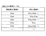
- FIG. 6C is a conceptual diagram showing a destination list management table.
- a communication ID for identifying a destination candidate for communication that can be specified is a communication ID for identifying a communication start request source. Associated and managed.
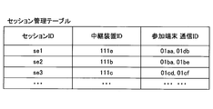
- FIG. 6D is a conceptual diagram showing a session management table.
- the relay device ID of the relay device 30 that relays the content data between the terminals 10.
- the communication ID indicating the terminal 10 serving as the transmission destination or the transmission source of the content data is managed in association with each other.
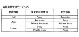
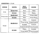
- a state change management DB 5009 configured by a state change management table as shown in FIGS. 7A and 7B is constructed.
- 7A and 7B are conceptual diagrams showing a state change management table.
- management information used for controlling a session between the terminals 10, state information before change indicating a communication state before being changed by a state management unit 53 described later, and a state management unit 53 Is managed in association with change information indicating the communication state after the change.
- management information, terminal information for identifying one of the start request terminal and the destination terminal, state information before change, and change information are managed in association with each other. .
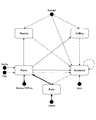
- the management system 50 changes the communication state “None” before the change of the start request terminal to “Private Calling”, and It is shown that the communication state “None” before the change of the destination terminal is changed to “Private Ringing”.
- the management information includes “Invite”, “Private Invite”, “Accept” shown in FIG. 7B, “Join”, “Call”, “Leave”, etc. shown in FIG. 7A.
- “Invite” is management information accompanying a communication start request. “Accept” is management information associated with a response to the start request, and indicates that communication start, that is, session establishment is permitted. “Join” is management information that accompanies the establishment of a session, and indicates that content data relay start is requested. “Call” is management information for requesting participation in an established session. “Leave” is management information for requesting termination of a session.
- FIG. 7C is a conceptual diagram showing a group information management table.
- group information indicating whether or not the communication ID is a group ID, the group name of the group identified by the group ID, and each terminal 10 constituting the group. are associated with each other and managed. That is, the group ID is an ID that defines a set of one or more communication IDs. The group ID is processed in the same manner as the communication ID on the destination list.
- the “group information” is set to “TRUE”, and the communication ID of the terminal 10 constituting the group and the item of the group name are set. Is done.
- “group information” is set to “FALSE”.
- FIG. 7D is a conceptual diagram showing a group state management table.
- the operational status of the group is associated and managed for each communication ID of each group.
- each functional part of the management system 50 will be described in detail.
- a relationship with main constituent elements for realizing each part of the management system 50 among the constituent elements shown in FIG. 4 will also be described.
- the transmission / reception unit 51 is executed by the network I / F 209 and transmits / receives various data (or information) to / from other terminals, devices, or systems via the communication network 2.
- the authentication unit 52 searches the authentication management table (see FIG. 6A) using the communication ID and password included in the login request information received via the transmission / reception unit 51 as search keys, and the same communication in the authentication management table. Authentication is performed by determining whether the ID and password are managed.
- the state management unit 53 manages the operating state and communication state of the terminal management table shown in FIG. 6B in accordance with a command from the CPU 201.
- 8 and 9 are state transition diagrams showing the transition of the communication state of the terminal 10 in one embodiment.
- the state management unit 53 is a communication state change rule realized by referring to the state change management table (A) and the state change management table (B) shown in FIGS. 7A and 7B (see FIGS. 8 and 9).
- the communication state of the terminal 10 is changed according to
- the state management unit 53 changes the communication state of the terminal 10 from “Private Ringing” or “Private Calling” to “ Change to “Private Accepted”.
- the state management unit 53 keeps the communication state “Private Accepted” as shown in FIG.
- the present invention is not limited to such a form. In this case, it is only necessary to be defined by the management system program so that the state management unit 53 can change the communication state according to the communication state transition rules shown in the state transition diagrams of FIGS.
- the session management unit 57 stores various information in the session management table (see FIG. 6D) or manages various information from the session management table in accordance with an instruction from the CPU 201 in order to manage a session for transmitting content data between the terminals 10. The process which reads is performed.
- the session control unit 58 controls a session in which content data is transmitted between the terminals 10 according to a command from the CPU 201. Examples of this control include control for establishing a session, control for causing the terminal 10 to participate in the established session, control for disconnecting the session, and the like. Specifically, the session management unit 57 generates a session ID for identifying the session, selects a relay device 30 that relays content data in the session, and the like.
- the storage / read processing unit 59 is also executed by the HDD 205 as an example from the CPU 201 and stores various data in the nonvolatile storage unit 5000 or the volatile storage unit 5100, or the nonvolatile storage unit 5000 or the volatile unit. Processing for reading various data stored in the storage unit 5100 is performed.
- FIG. 10 is a conceptual diagram showing a state of transmission / reception of content data and various management information in the communication system.
- Session sei is established.
- a session for transmitting / receiving content data is established between the terminals 10 via the relay device 30.
- these sessions are collectively shown as a content data session sed. That is, the content data session sed is a session used for a video conference.
- control session participation When the management system 50 (an example of a control system) of the communication system 1 establishes a content data session sed for transmitting content data (an example of information) between the terminals 10, Control session participation.
- the transmission / reception unit 51 (an example of the participation control unit) of the management system 50 transmits the participation impossible notification to the terminal 10cd (an example of another terminal), thereby entering the session by the terminal 10cd. Refuse to participate.
- the transmission / reception unit 51 transmits the relay device connection information to the terminal 10cd (an example of another terminal), thereby executing control for causing the terminal 10cd to participate in the session. Accordingly, it is not necessary to select the presence / absence of participation restriction every time a request to start communication is made on the start request source terminal 10aa side, thereby reducing the load on the user.
- the terminal management DB 5003 (an example of the state information management unit) of the management system 50 participates in this session when the content data session sed is established based on the communication start request specifying the communication ID “01xx”.
- “Private Busy” (an example of first state information) is managed as a communication state.
- the terminal management DB 5003 of the management system 50 when the content data session sed is established based on the communication start request specifying the communication ID “01db”, each terminal (10aa) participating in this session. , 10 db), “Busy” (an example of second state information) is managed as state information indicating the communication state.
- the transmission / reception unit 51 By transmitting a participation impossible notification to 10 cd, participation in the session by the terminal 10 cd is rejected.
- the transmission / reception unit 51 receives the terminal 10cd.
- control for causing the terminal 10cd to participate in the session is executed. In this way, by managing the state of the terminal 10 according to the destination, it is possible to control participation according to the destination.
- the communication ID “01xx” is a destination indicating a call center (an example of a group) constituted by a plurality of terminals (10ba, 10db), and the communication ID “01db” is a destination indicating the terminal 10db constituting the call center. is there. As a result, it is possible to control so that another terminal 10 does not participate in the content data session sed established with the call center as the destination.
- the group information management DB 5010 (an example of a group management unit) manages each communication ID (an example of terminal identification information) that identifies each terminal 10 constituting the group for each communication ID indicating a group.
- the transmission / reception unit 51 (an example of a start request receiving unit) receives a communication start request specifying a destination from the terminal 10 that is the communication start request source.
- the session control unit 58 (an example of a selection unit) associates with the communication ID of the specified group in the group information management DB 5010.
- the communication ID of at least one terminal 10 is selected as a communication partner with respect to the terminal 10 that is the communication start request source, that is, the calling terminal, from among the communication IDs of the terminals that have been received.
- the management system 50 can select a calling terminal when receiving a communication start request specifying a group as a destination.
- Specific information management means (an example of a group information management DB 5010) manages group information “TRUE” (an example of specific information) for specifying a destination indicating a group from a plurality of destinations.
- group information “TRUE” an example of specific information
- the transmission / reception unit 51 receives a communication start request specifying a destination specified as a destination indicating a group by the group information “TRUE”
- the session control unit 58 determines whether the communication start request source
- the at least one terminal 10 is selected as a communication partner of the terminal 10.
- the management system 50 can select the calling terminal when receiving a communication start request selected with the group as the destination.
- FIG. 11 is a sequence diagram illustrating processing in a preparation stage for starting a call between terminals. Note that FIG. 11 illustrates processing in which various types of management information are transmitted and received through the management information session sei.
- the operation input accepting unit 12 accepts the power on and turns on the power (step S21).
- the login request unit 13 automatically transmits login request information indicating a login request from the transmission / reception unit 11 to the management system 50 via the communication network 2 in response to the reception of the power ON (step S22).
- This login request information includes a communication ID and a password for identifying the terminal 10aa which is the own terminal as a request source.
- These communication ID and password are data read from the nonvolatile storage unit 1000 via the storage / reading processing unit 19 and sent to the transmission / reception unit 11.
- the management system 50 that is the receiving side can grasp the IP address of the terminal 10aa that is the transmitting side.
- the authentication unit 52 of the management system 50 searches the authentication management table (see FIG. 6A) using the communication ID and password included in the login request information received via the transmission / reception unit 51 as search keys, and performs authentication. Authentication is performed by determining whether the same communication ID and password are managed in the management DB 5002 (step S23).
- the state management unit 53 displays the terminal management table. (See FIG. 6B), the IP address of the terminal 10aa is stored in association with each record indicated by the communication ID and terminal name of the terminal 10aa (step S24-1). As a result, in the terminal management table shown in FIG. 6B, the terminal ID address “1.2.1.3” is managed in association with the communication ID “01aa”.
- the state management unit 53 sets the operation state “ON line” and the communication state “None” of the terminal 10aa, and records indicated by the communication ID and terminal name of the terminal 10aa in the terminal management table (see FIG. 6B). Every time, the set operation state and communication state are associated and stored (step S24-2).
- the transmission / reception unit 51 of the management system 50 sends the login request terminal (terminal 10aa) that has made the login request to the authentication result information indicating the authentication result obtained by the authentication unit 52 via the communication network 2. (Step S25).
- the transmission / reception unit 11 requests the management system 50 via the communication network 2 for a destination list. Is sent to the destination list request information (step S26). Thereby, the transmission / reception unit 51 of the management system 50 receives the destination list request information.
- the storage / read processing unit 59 searches the destination list management table (see FIG. 6C) using the communication ID “01aa” of the login request terminal (terminal 10aa) that requested the login as a search key, and logs in to the login request terminal (terminal The communication IDs (“01xx”, “01ab”, etc.) of destination candidates that can be specified in 10aa) are read (step S27).
- the storage / read processing unit 59 uses the read communication ID (“01xx”, “01ab”, etc.) as a search key, and uses the terminal management table (see FIG. 6B) and the group information management table (see FIG. 7C). A search is performed to read a destination name (“call center”, “customer: Tokyo office AB terminal”, etc.) corresponding to this communication ID.
- the transmission / reception unit 51 of the management system 50 receives data of the destination list frame (data of the destination list frame 1100-1 portion shown in FIG. 12) from the nonvolatile storage unit 5000 via the storage / read processing unit 59.
- Step S28 the destination list frame and the destination candidate communication ID and destination name read by the storage / reading processing unit 59, including “destination list information (destination list frame, communication ID, destination”). Name) ”is transmitted to the start requesting terminal (terminal 10aa) (step S29).
- the transmission / reception unit 11 receives the destination list information
- the storage / reading processing unit 19 stores the destination list information in the volatile storage unit 1100 (step S30).
- the storage / read processing unit 59 of the management system 50 uses the communication candidate ID (“01ab”, etc.) as the search key as a search key, and uses the terminal management table (see FIG. 6B) and the group information management table (see FIG. 7D). The search is performed and the corresponding operating state and communication state are read for each communication ID (step S31).
- the transmission / reception unit 51 sends status information including the communication ID as the search key used in step S31 and the operation status and communication status of the corresponding destination candidate to the login request terminal via the communication network 2. Transmit (step S32).
- the storage / read processing unit 19 of the login request terminal (terminal 10aa) sequentially stores the state information received from the management system 50 in the volatile storage unit 1100 (step S33). Therefore, the log-in request terminal (terminal 10aa) receives the above-described status information of each terminal, so that the call center or the terminal 10ab that is a destination candidate that can talk to the log-in request terminal (terminal 10aa) as the start request terminal. The current operating state and communication state of each can be acquired.
- the destination list creation unit 20 of the login request terminal (terminal 10aa), based on the destination list information stored in the volatile storage unit 1100 and the terminal state information, the operation status of the terminal 10 as a destination candidate. And create a destination list reflecting the communication status.
- the display control unit 16 displays the destination list on the display 120aa at a predetermined timing (step S34).
- FIG. 12 is a diagram showing a display example of a destination list.
- the destination list includes destination candidate communication ID 1100-2, terminal name 1100-3, and icons 1100-4a to 1100- reflecting status information in the destination list frame 1100-1. 4c and the like.
- the destination list creation unit 20 assigns a call enable icon 1100-4b to the destination candidate.
- the destination list creation unit 20 also assigns a busy icon 1100-4c to the destination candidate when the operation status of the destination candidate is “ON line (during communication)”.
- the destination list creation unit 20 also assigns an OFF line icon 1100-4a to this destination candidate when the operation status of the destination candidate is “OFF line”.
- FIG. 13 is a sequence diagram illustrating processing for requesting the start of communication. Note that FIG. 13 illustrates processing in which various types of management information are transmitted and received through the management information session sei.
- the terminal 10aa as the start requesting terminal has at least one destination candidate whose operation state is “ON line” among the destination candidates displayed in the destination list frame 1100-1, that is, the communication ID (“01ab” or “ 01xx ”etc.) can be selected and a communication start request can be made.
- the operation input receiving unit 12 receives the selection of the destination candidate (step S41). Subsequently, the transmission / reception unit 11 of the terminal 10aa transmits start request information including the communication ID “01aa” of the start request terminal (terminal 10aa) and the communication ID of the destination candidate to the management system 50 together with the IP address of the start request terminal. (Step S42). As a result, the transmission / reception unit 51 of the management system 50 receives the start request information and grasps the IP address “1.2.1.3” of the start request terminal (terminal 10aa) that is the transmission source. .
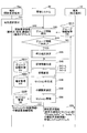
- the storage / reading processing unit 59 searches the group information management table (see FIG. 7D) using the communication ID included in the start request information as a search key, and reads the corresponding group information (step S43). Subsequently, the session control unit 58 determines whether or not the group information read in step S43 is “TRUE” (step S44).
- step S44 When it is determined in step S44 that the group information is “TRUE”, the session control unit 58 selects the terminal 10aa from the terminals 10 constituting the group selected as the destination candidate in the start requesting terminal (terminal 10aa). A terminal 10 (calling terminal) to be called as a communication partner is determined.
- step S45 is a flowchart showing processing for determining a calling terminal.
- the storage / reading processing unit 59 searches the group information management table (see FIG. 7C) using the communication ID of the destination candidate included in the start request information (for example, “01xx”) as a search key, and selects the corresponding group.
- the communication ID of the configuring terminal 10 is read (step S45-1).
- the description will be continued with respect to the case where the communication ID (“01ba”, “01db”) is read in step S45-1.
- the state management unit 53 searches an arbitrary first communication ID (for example, “01ba”) among the communication IDs (“01ba”, “01db”) read in step S45-1 as a search key. Then, the terminal management table (see FIG. 6B) is searched, and the corresponding operating state is read (step S45-2).
- the session control unit 58 determines whether or not the operating state read in step S45-2 is “ON line (communicable”) (step S45-3). When it is determined that the operating state is “ON line (communicable”), the session control unit 58 identifies the terminal (for example, the terminal 10ba) identified by the communication ID used as the search key in step S45-2. Is selected as the calling terminal (step S45-4).
- step S45-3 If it is determined in step S45-3 that the operating state is not ("ON line (communicable")), the state management unit 53 determines each communication ID ("01ba", "01") read in step S45-1.
- the terminal management table (see FIG. 6B) is searched using an arbitrary second communication ID (for example, “01db”) of the “01db”) as a search key, and the corresponding operating state is read (step S45-5).
- the session control unit 58 determines whether or not the operating state read in step S45-5 is “ON line (communicable”) (step S45-6). If the operating state is determined to be “ON line (communicable)”, the session control unit 58 determines the terminal (eg, terminal) identified by the communication ID used as the search key in step S45-2. 10db) is selected as the calling terminal (step S45-7).
- step S45-6 If it is determined in step S45-6 that the operating state is not ("ON line (communicable)", the state management unit 53 is read in step S45-1 in the terminal management table (see FIG. 6B). The corresponding operation state is periodically read using each communication ID (“01ba”, “01db”) as a search key (step S45-8).
- the session control unit 58 determines whether or not the operating state read in step S45-5 has been changed to “ON line (communicable”) (step S45-9). When it is determined that the state has been changed to “ON line (communicable)”, the session control unit 58 selects the terminal 10 whose operation state has been changed to “ON line (communicable)” as a calling terminal (step) If it is not determined that the operating state read in step S45-5 has been changed to “ON line (communicable”) (NO in step S45-9), step S45 is performed. The process of -8 is repeatedly executed.
- the session control unit 58 generates management information related to the control of the content data session sed between the terminal 10aa and the destination terminal 10 (step S46).
- the session control unit 58 uses the management information “Private Invite” indicating that the start of the content data session sed with participation restriction is requested. Is generated.
- the session control unit 58 receives management information “Invite” indicating that the start of the content data session sed without participation restriction is requested. Generate.
- the start control of the content data session sed with participation restriction is executed. This is because the group as the destination is a call center (see FIG. 7C), and it is not assumed that a third party participates in the established session.
- the method of setting the participation restriction is not limited to the above method.
- the state management unit 53 changes the communication state corresponding to the communication ID “01aa” of the start requesting terminal (terminal 10aa) and the communication ID of the destination terminal in the terminal management table (see FIG. 6B) (step S47). -1).
- the state management unit 53 searches the state change management table (see FIG. 7B) using the management information (“Private Invite” or “Invite”) generated in step S46 as a search key, and for each terminal information, Read the corresponding pre-change state information and change information.
- the state management unit 53 changes the state information of each terminal 10 based on the read terminal information, pre-change state information, and change information.
- the state management unit 53 displays the state information corresponding to the communication ID of the start request terminal (10aa) in the terminal management table (see FIG. 6B). Then, “None” indicated by the pre-change state information is changed to “Private Calling” indicated by the change information. In addition, the state management unit 53 changes the operation state associated with each communication ID of the start request terminal (terminal 10aa) and the destination terminal to “ON line (during communication)” in the terminal management table (step) S47-2).
- step S43 When the group information read in step S43 is “TRUE”, the state management unit 53 updates the operating state of the group managed in the group state management table (see FIG. 7D) (step S47— 3).
- the group operating state update processing by the management system 50 will be described with reference to FIG. The process is executed at an arbitrary timing, for example, when the operating state of the terminals 10 constituting the group is changed as described above. Note that the update timing of the operating state is not particularly limited, and may be executed at regular intervals, for example.
- the storage / reading processing unit 59 refers to the group information management table of FIG. 7C and selects one group ID whose group information is “TRUE” (step S47-3-1). Subsequently, the storage / read processing unit 59 reads out one of the communication IDs of the terminals constituting the group selected in Step S501 (Step S47-3-2). Subsequently, the state management unit 53 refers to the terminal management table (see FIG. 6B), and reads the operating state corresponding to the communication ID read in step S47-3-2 (step S47-3-3).
- the state management unit 53 determines whether or not the operation state read in step S503 is “ON line (communicable)” (step S47-3-4). If it is determined in step S47-3-4 that the operation state is “ON line (communication possible)”, the state management unit 53 sets the operation state of the group ID selected in step S47-3-1 to “ “ON line (communicable)” is stored, and the information is stored in the group state management table of FIG. 7D.
- step S47-3-4 determines that all terminals included in the group selected in step S47-3-1. It is determined whether or not 10 communication IDs have been read (step S47-3-6). If it is determined in step S47-3-6 that the communication IDs of all the terminals 10 have been read, the state management unit 53 sets the operation state of the group ID selected in step S47-3-1 to “OFF line”. And stores the information in the group status management table of FIG. 7D (step S47-3-7). If it is determined in step S47-3-6 that the communication IDs of all the terminals 10 have not been read, the process of step S47-3-2 is executed.
- step S47-3-8 when each of the above processes is completed for all the group IDs whose group information is “TRUE”, the process ends. Otherwise, the process returns to step S47-3-1, and The process for the group ID is executed.
- the operating state of the group can be managed, so that the user of each terminal 10 can communicate without being aware that the destination registered in the destination list is the terminal 10 or a group.
- a call can be started by specifying a possible destination.
- the session control unit 58 identifies a session (content data session sed) for performing communication with the destination terminal requested by the start requesting terminal (terminal 10aa) (for example, a session ID for content data). “Se1”) is generated (step S48).
- the session control unit 58 of the management system 50 selects the relay device 30 for relaying the content data in the content data session sed between the start requesting terminal (terminal 10aa) and the destination terminal (step) S49).
- the relay device 30e is selected by the session management unit 57 will be described below.
- the session management unit 57 in the session management table (see FIG. 6D), the session ID generated in step S48 and the relay device ID “of the relay device 30e selected in step S49. 111e ”, the communication ID of the start request terminal (terminal 10aa) as the communication ID of the participating terminal participating in the session, and the communication ID (eg,“ 01db ”) of the destination terminal are stored and managed in association with each other (step S50). ).
- the transmission / reception unit 51 selects the start request terminal (terminal 10aa) via the communication network 2 by using the session ID generated in step S48 and the restriction information indicating presence / absence of participation restriction of the terminal 10 in step S49.
- the relay device connection information used for connecting to the relay device 30e thus transmitted is transmitted (step S51).
- the relay device connection information can include the IP address “1.1.1.3” of the relay device 30e, authentication information, a port number, and the like. Accordingly, the terminal 10aa can grasp the relay device connection information used for connecting to the relay device 30e used for relaying the content data in the execution of the session with the session ID “se1”.
- the transmission / reception unit 51 includes the communication ID “01aa” of the start requesting terminal (terminal 10aa), the management information generated in Step S46 (“Private Invite” or “Invite”), and the session ID generated in Step S48.
- the start request information including “se1”, the relay device connection information used for connecting to the relay device 30e, and the IP address of the management system 50 are transmitted to the destination terminal (step S52).
- the transmission / reception unit 11 of the destination terminal receives the start request information, relay device connection information used for connecting to the relay device 30e used for relaying content data, and the management system 50 that is the transmission source.
- the IP address “1.1.1.2” is grasped.
- FIG. 16 is a sequence diagram illustrating processing for permitting a request to start communication.
- FIG. 17A is a diagram illustrating an example of a start permission reception screen when the management information transmitted from the management system 50 is “Private Invite”.
- FIG. 17B is a diagram illustrating an example of a start permission reception screen when the management information transmitted from the management system 50 is “Invite”.
- the management information is “Private Invite”
- there is a participation restriction such as “This meeting is a participation restriction meeting”. Is shown.
- the operation input reception unit 12 receives a response to permit the start of communication (session establishment) with the start requesting terminal. Subsequently, the transmission / reception unit 11 of the destination terminal, the communication ID of the destination terminal, the communication ID “01aa” of the start request terminal (terminal 10aa), the management information “Accept” indicating that session establishment is permitted, and the session ID “se1” "Is sent to the management system 50 (step S62).
- the state management unit 53 transmits the communication ID “01aa” of the start request terminal (terminal 10aa) and the communication of the destination terminal in the terminal management table (see FIG. 6B).
- the communication state corresponding to the ID is changed (step S63).
- the state management unit 53 searches the state change management table (see FIG. 7B) using the management information (“Accept”) included in the start response information as a search key, and corresponds to the pre-change state for each terminal information. Read information and change information.
- the state management unit 53 changes the state information of each terminal 10 based on the read terminal information, pre-change state information, and change information.
- the state management unit 53 changes to “Private Accepted”, and the communication before the change. If the state is “Calling”, it is changed to “Accepted”. Similarly, if the communication state before the change of the destination terminal managed in the terminal management table is “Private Ringing”, the state management unit 53 changes it to “Private Accepted”, and the communication state before the change is “Ringing”. "Is changed to" Accepted ".
- the transmission / reception unit 51 transmits start response information including the communication ID of the destination terminal, the management information “Accept”, and the session ID “se1” to the start requesting terminal (terminal 10aa) (step S64).
- the start request terminal (terminal 10aa) transmits the session ID “se1” and the relay device connection information acquired in step S51 to the relay device 30e by the transmission / reception unit 11, thereby the relay device 30e is connected (step S65).
- the destination terminal connects to the relay device 30e by transmitting the session ID “se1” and the relay device connection information acquired in step S52 to the relay device 30e by the transmission / reception unit 11 (step S66).
- the transmission / reception unit 11 of the start request terminal receives the communication ID “01aa”, the session ID “se1” of the start request terminal (terminal 10aa), and the management information “Join” indicating that the start of relay is requested. Is transmitted to the management system 50 (step S71-1).
- the state management unit 53 displays the communication state corresponding to the communication ID “01aa” of the start request terminal (terminal 10aa) in the terminal management table (see FIG. 6B). Change (step S72-1).
- the state management unit 53 searches the state change management table (see FIG. 7A) using the management information (“Join”) received in step S71-1 as a search key, and the corresponding pre-change state information and change information. Is read.
- the state management unit 53 changes the state information of the terminal 10aa based on the read pre-change state information and change information.
- the state management unit 53 changes to “Private Busy” and changes the communication state before the change. Is “Accepted”, it is changed to “Busy”.
- the management system 50 transmits relay start request information including the communication ID “01aa” of the start request terminal (terminal 10aa) and the session ID “se1” to the relay device 30e (step S73-1). Thereby, the content data session sed between the relay requesting terminal (terminal 10aa) and the relay device 30e is established.
- a content data session sed between the destination terminal (terminal 10db) and the relay device 30e is established (steps S71-2 to S71-2). S73-2).
- the relay device 30e The content data (image data and sound data) is relayed between the start request terminal (10aa) and the destination terminal. Thereby, the start request terminal (10aa) and the destination terminal can start the video conference.
- the terminal 10 participating in the video conference that is, the display 120 of the terminal 10 participating in the established session is a video conference using a session with participation restriction, or there is no participation restriction. It may be possible for a participant to recognize whether or not there is a restriction on participation in a video conference, for example, by displaying whether the video conference is using a session.
- FIGS. 18A and 18B show examples of screens displayed on the display 120 while the terminal 10 is performing a video conference with other terminals.
- the display control unit 16 of the terminal 10 outputs an auxiliary area 510 for displaying detailed information regarding the conference in addition to the video 500 captured by the partner terminal 10.
- the auxiliary area includes information such as the communication ID of the other party.
- the display control unit 16 of the terminal 10 determines whether the conference being executed is “participation restricted” based on the restriction information (see step S51) or the management information (see step S52) transmitted from the management system 50. Information indicating whether or not can be output to any location in the auxiliary area 510.
- the display control unit of the terminal 10 may output a key-shaped icon to the auxiliary area 510 when a user starts a “participation restricted” conference and a session related to the conference is established. it can. Depending on whether or not the icon is displayed, the user of the terminal 10 can confirm whether or not the conference in which he / she is participating is “participation restricted”.
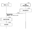
- FIG. 19 is a sequence diagram showing the participation process in the content data session. Note that FIG. 19 illustrates processing in which various types of management information are transmitted and received through the management information session sei.
- the terminal 10cd operates as a participation request terminal that transmits participation request information.
- the destination list is displayed on the display 120cd of the terminal 10cd by the login process described with reference to FIG.
- the user of the participation request terminal (terminal 10cd) operates the operation button 108 to select the terminal whose operation state is communicating (here, the terminal 10aa).
- the operation input accepting unit 12 accepts a request to participate in the content data session sed that has already been established (step S101).
- the transmission / reception unit 11 of the participation request terminal requests to participate in the communication ID “01cd” of the own terminal 10cd, the communication ID “01aa” of the selected terminal 10aa, and the content data session. Is sent to the management system 50 (step S102).
- step S103 When the management system 50 receives the session participation request information, does the management system 50 continue the process for connecting the participation request terminal (terminal 10cb) and the terminals participating in the content data session sed (terminals 10aa and 10db)? Judgment is made (step S103).
- the processing in step S103 will be described in detail with reference to FIG.
- FIG. 20 is a process flow diagram illustrating participation determination processing based on the communication state.
- the storage / reading processing unit 59 refers to the terminal management table (FIG. 6B), and uses the communication ID “01aa” of the terminal participating in the session (terminal 10aa) included in the participation request information as a search key.
- the state is read (step S103-1).
- the session control unit 58 determines whether or not the read communication state is “Private Busy” (step S103-2). If the read communication state is not “Private Busy”, the session control unit 58 determines that the participation requesting terminal can participate in the session (step S103-3) and ends the process.
- the session control unit 58 determines that participation in the session by the participation requesting terminal is impossible (step S103-4). Then, the transmission / reception unit 11 transmits a participation impossible notification for notifying that participation in the session cannot be performed to the participation request terminal (terminal 10cd) (step S103-5).
- the participation request terminal (terminal 10 cd) receives the participation impossible notification, it displays it on the display 120.
- the management system 50 transmits content data to the terminal 10cd between the terminals (10aa, 10db). Execute the control to participate in the session.
- a process of transmitting relay apparatus connection information for connecting to the relay apparatus 30e to which the terminal (10aa, 10db) is connected to the terminal 10cd can be cited.
- the terminal participation control is not particularly limited, and examples thereof include a method described in JP2012-50063A.
- the management system 50 and the program providing system 90 in each of the above embodiments may be constructed by a single computer, or may be constructed by a plurality of computers arbitrarily assigned by dividing each unit (function or means). It may be.
- the program transmitted by the program providing system 90 may be transmitted by dividing it into a plurality of modules. It may be transmitted.
- a plurality of modules may be divided and transmitted from each computer.
- the terminal IP address is managed in the terminal management table shown in FIG. 6B.
- the present invention is not limited to this, and the relay device 30 is specified on the communication network 2.
- Each FQDN (Fully Qualified Domain Name) may be managed as long as the relay device specifying information or the terminal specifying information for specifying the terminal 10 on the communication network 2 is used.
- an IP address corresponding to the FQDN is acquired by a known DNS (Domain (Name System) server.
- video conference is used as a term that can be replaced with “video conference”.
- the case of the video conference system has been described as an example of the communication system 1.
- the present invention is not limited to this, and a car navigation system may be used.
- one of the terminals 10 corresponds to a car navigation device mounted on a car
- the other of the terminals 10 is mounted on a management terminal or management server of a management center that manages car navigation, or another car. This corresponds to a car navigation device.
- FIG. 21 is a diagram illustrating an example of a system configuration when the terminal 10 is employed as a car navigation device.
- one terminal 10 corresponds to the car navigation device 200-2 mounted on the automobile 601.
- the other terminal 10 corresponds to the management terminal 200-1 used by the communicator of the management center 604, the management server 603 that manages the car navigation device, or the car navigation device 200-3 installed in another automobile 602. To do.
- FIG. 22 shows an example of a configuration diagram of the car navigation apparatus.
- the car navigation apparatus includes a control unit 611 that controls the entire apparatus, a GPS receiver 612, a vehicle speed sensor 613, a gyro sensor 614, road map data 615, and the like.
- the terminal 10 of this embodiment is connected to the control unit 611.
- the control unit 611 is an information processing device such as a microcomputer, and provides a function as a car navigation device by executing a program.
- the GPS receiver 612 supplements the GPS satellite and outputs the coordinates of the current position.
- the vehicle speed sensor 613 is a sensor that detects the speed of the automobile (wheel rotation speed).
- the gyro sensor 614 is a sensor that detects an angular velocity, and the traveling direction of the vehicle can be detected by integrating the angular velocity.
- the road map data 615 is data representing a road as a combination of nodes and links, and may be downloaded from the outside or held in advance by the vehicle.
- the road map is displayed on the display 120.
- the control unit 611 estimates the position of the host vehicle by applying autonomous navigation that accumulates the travel distance detected by the vehicle speed sensor 613 in the travel direction detected by the gyro sensor 614 to the position information detected by the GPS receiver 612.
- the vehicle position is displayed on the road map by the vehicle mark or the like.
- the car navigation device is connected to the communication network 2 using a function of the terminal 10 or using a function of a mobile phone via a mobile phone line or the like.
- the terminal 10 Since the terminal 10 displays a screen as shown in FIG. 12 on the display 120, the occupant selects the destination terminal from the list of destination terminals displayed on the display 120. After logging in, camera image data and sound data can be sent and received. Further, the information processing apparatus can capture display data such as a road map and a TV image by the operation of the passenger. In this case, the car navigation device can transmit display data to the car navigation device of the counterpart terminal.
- image data, sound data, and display data can be transmitted and received in the same manner as the terminal 10 in the office only by the mounting place being a mobile body.
- the communication system 1 may be a sound conference system or a PC (Personal Computer) screen sharing system.
- the communication system 1 may be an IP (Internet Protocol) phone, an Internet phone, or a mobile phone communication system.
- the terminal 10 corresponds to a telephone such as a mobile phone.
- the content data may be data indicating in-vivo information such as sound data generated in the body such as a pulse sound and heartbeat, an electrocardiogram waveform, image data indicating changes in body temperature, or coordinate data.
- the communication system 1 of the said embodiment can also be used as a telemedicine system.
- image data and sound data have been described as an example of content data.
- touch data may be used.
- the feeling that the user touched on one terminal side is transmitted to the other terminal side.
- the content data may be smell data.
- the odor (odor) on one terminal side is transmitted to the other terminal side.
- the content data may be at least one of image data, sound data, tactile data, and olfactory data.
Landscapes
- Engineering & Computer Science (AREA)
- Multimedia (AREA)
- Signal Processing (AREA)
- Theoretical Computer Science (AREA)
- General Engineering & Computer Science (AREA)
- Computer Hardware Design (AREA)
- Health & Medical Sciences (AREA)
- Bioethics (AREA)
- General Health & Medical Sciences (AREA)
- Computer Security & Cryptography (AREA)
- Software Systems (AREA)
- Physics & Mathematics (AREA)
- General Physics & Mathematics (AREA)
- Computer Networks & Wireless Communication (AREA)
- Automation & Control Theory (AREA)
- Business, Economics & Management (AREA)
- General Business, Economics & Management (AREA)
- Telephonic Communication Services (AREA)
- Two-Way Televisions, Distribution Of Moving Picture Or The Like (AREA)
- Computer And Data Communications (AREA)
Abstract
Description
図1は、実施の形態にかかる通信システムとしての通信システム1の概略図であり、まずは図1を用いて、通信システム1の概略を説明する。通信システム1には、通信管理システムを介して一方の通信端末から他方の通信端末に一方向でコンテンツデータを通信するデータ提供システムや、通信管理システムを介して複数の通信端末間で情報や感情等を相互に伝達するコミュニケーションシステムが含まれる。このコミュニケーションシステムは、コミュニケーション管理システム(「通信管理システム」に相当)を介して複数のコミュニケーション端末(「通信端末」に相当)間で情報や感情等を相互に伝達するためのシステムであり、テレビ会議システムやテレビ電話システム、音会議システム、音声電話システム、PC(Personal Computer)画面共有システム等が例として挙げられる。
次に、通信システム1のハードウェア構成を説明する。図2は、端末10の外観図である。以下、端末10の長手方向をX軸方向、水平面内でX軸方向に直交する方向をY軸方向、X軸方向及びY軸方向に直交する方向(鉛直方向)をZ軸方向として説明する。
次に、通信システム1の機能構成について説明する。図5は、通信システム1を構成する各端末、装置及びシステムの機能ブロック図である。図5では、端末10、中継装置30、及び管理システム50が、通信ネットワーク2を介してデータ通信することができるように接続されている。また、図1に示されているプログラム提供システム90、及びメンテナンスシステム100は、テレビ会議の通信において直接関係ないため、図5では省略されている。
端末10は、送受信部11、操作入力受付部12、ログイン要求部13、撮像部14、音入出力部15、表示制御部16、記憶・読出処理部19、及び宛先リスト作成部20を有している。これら各部は、図3に示されている各構成要素のいずれかが、ROM102に記憶されているプログラムに従ったCPU101からの命令によって動作することで実現される機能又は手段である。また、端末10は、RAM103によって構築される揮発性記憶部1100、及びフラッシュメモリ104によって構築される不揮発性記憶部1000を有している。
次に、端末10の各部を説明する。
次に、中継装置30の機能又は手段について説明する。中継装置30は、送受信部31、及び記憶・読出処理部39を有している。これら各部は、図4に示されている各構成要素のいずれかが、ROM202に記憶されているプログラムに従ったCPU201からの命令によって動作することで実現される機能又は手段である。また、中継装置30は、HD204により構築され、中継装置30の電源をOFFにしても各種データや情報の記憶が維持される不揮発性記憶部3000を有している。
次に、中継装置30の各機能構成について詳細に説明する。なお、以下では、中継装置30の各部を説明するにあたって、図4に示されている各構成要素のうち、中継装置30の各部を実現させるための主な構成要素との関係も説明する。
次に、管理システム50の機能又は手段について説明する。管理システム50は、送受信部51、認証部52、状態管理部53、セッション管理部57、セッション制御部58、及び記憶・読出処理部59を有している。これら各部は、各構成要素のいずれかが、ROM202に記憶されているプログラムに従ったCPU201からの命令によって動作することで実現される機能又は手段である。また、管理システム50は、HD204により構築され、管理システム50の電源をOFFにしても各種データや情報の記憶が維持される不揮発性記憶部5000を有している。更に、管理システム50は、RAM203によって構築される揮発性記憶部5100を有している。
また、不揮発性記憶部5000には、図6Bに示されているような端末管理テーブルによって構成されている端末管理DB5003が構築されている。なお、図6Bは、端末管理テーブルを示す概念図である。この端末管理テーブルでは、各端末10の通信ID毎に、宛先名(端末名)、各端末10の稼動状態、他の端末との通信の状態を示す通信状態、及び端末10のIPアドレスが関連付けられて管理される。ここで、稼動状態としては、電源がオンされ、通信が可能または通信中の状態であるONラインと、電源がオンされていないなど、通信が可能でない状態であるOFFラインとがある。
更に、不揮発性記憶部5000には、図6Cに示されているような宛先リスト管理テーブルによって構成されている宛先リスト管理DB5004が構築されている。なお、図6Cは、宛先リスト管理テーブルを示す概念図である。この宛先リスト管理テーブルでは、端末10間でコンテンツデータを送信するセッションにおいて、通信の開始要求元を識別するための通信IDに対して、指定可能な通信の宛先候補を識別するための通信IDが関連付けられて管理される。
また、この不揮発性記憶部5000には、図6Dに示されているようなセッション管理テーブルによって構成されているセッション管理DB5005が構築されている。なお、図6Dは、セッション管理テーブルを示す概念図である。このセッション管理テーブルでは、端末10間でコンテンツデータが通信されるセッションを識別するためのセッションID毎に、このセッションにおいて、端末10間でコンテンツデータを中継する中継装置30の中継装置ID、このセッションにおいてコンテンツデータの送信先あるいは送信元となる端末10を示す通信IDが関連付けられて管理される。
また、不揮発性記憶部5000には、図7A及び図7Bに示されているような状態変更管理テーブルによって構成されている状態変更管理DB5009が構築されている。なお、図7A及び図7Bは、状態変更管理テーブルを示す概念図である。図7Aの状態変更管理テーブルAでは、端末10間のセッションの制御に用いられる管理情報と、後述の状態管理部53によって変更される前の通信状態を示す変更前状態情報と、状態管理部53によって変更された後の通信状態を示す変更情報とが関連付けられて管理される。また、図7Bの状態変更管理テーブルBでは、管理情報と、開始要求端末および宛先端末のいずれかを識別するための端末情報と、変更前状態情報と、変更情報とが関連付けられて管理される。
不揮発性記憶部5000には、図7Cに示されているようなグループ情報管理テーブルによって構成されているグループ情報管理DB5010が構築されている。なお、図7Cは、グループ情報管理テーブルを示す概念図である。このグループ情報管理テーブルでは、通信ID毎に、その通信IDがグループIDであるか否かを表すグループ情報と、そのグループIDによって識別されるグループのグループ名と、そのグループを構成する各端末10の各通信IDと、を関連付けて管理する。すなわち、グループIDは、一以上の通信IDの集合を定義するIDである。グループIDは、宛先リスト上では、通信IDと同様に処理される。
不揮発性記憶部5000には、図7Dに示されているようなグループ状態管理テーブルによって構成されているグループ状態管理DB5011が構築されている。なお、図7Dは、グループ状態管理テーブルを示す概念図である。このグループ状態管理テーブルでは、各グループの通信ID毎に、グループの稼動状態が関連付けられて管理される。
次に、管理システム50の各機能部について詳細に説明する。なお、以下では、管理システム50の各部を説明するにあたって、図4に示されている各構成要素のうち、管理システム50の各部を実現させるための主な構成要素との関係も説明する。
以上が、通信システム1の構成及び機能(又は手段)の説明であり、続いて、通信システム1における処理方法を説明する。まずは、図10を用いて、通信システム1における処理・動作の概要を説明する。図10は、通信システムにおけるコンテンツデータ、及び各種管理情報の送受信の状態を示した概念図である。
上記各実施の形態における管理システム50、及びプログラム提供システム90は、単一のコンピュータによって構築されてもよいし、各部(機能又は手段)を分割して任意に割り当てられた複数のコンピュータによって構築されていてもよい。また、プログラム提供システム90が単一のコンピュータによって構築されている場合には、プログラム提供システム90によって送信されるプログラムは、複数のモジュールに分けて送信されるようにしてもよいし、分けないで送信されるようにしてもよい。更に、プログラム提供システム90が複数のコンピュータによって構築されている場合には、複数のモジュールが分けられた状態で、各コンピュータから送信されるようにしてもよい。
11 送受信部
12 操作入力受付部
13 ログイン要求部
14 撮像部
15 音入出力部
16 表示制御部
19 記憶・読出処理部
20 宛先リスト作成部
30 中継装置
50 通信管理システム
51 送受信部
52 認証部
53 状態管理部
57 セッション管理部
58 セッション制御部
59 記憶・読出処理部
5000 不揮発性記憶部
5002 認証管理DB
5003 端末管理DB
5004 宛先リスト管理DB
5005 セッション管理DB
5009 状態変更管理DB
5010 グループ情報管理DB
5011 グループ状態管理DB
Claims (9)
- 通信端末間で情報を送信するためのセッションが確立されているときに、他の通信端末の前記セッションへの参加を制御する制御システムであって、
通信端末からの第1の宛先を指定した通信の開始要求に基づいて、前記セッションが確立されていた場合には、前記他の通信端末による前記セッションへの参加を拒否する一方で、前記通信端末からの前記第1の宛先とは異なる第2の宛先を指定した通信の開始要求に基づいて前記セッションが確立されていた場合には、前記他の通信端末を前記セッションへ参加させる制御を実行する参加制御手段を有することを特徴とする制御システム。 - 前記通信端末からの前記第1の宛先を指定した通信の開始要求に基づいて前記セッションが確立されているときには、該セッションに参加している各通信端末に関連付けて、通信の状態を示す第1の状態情報を管理し、前記通信端末からの前記第2の宛先を指定した通信の開始要求に基づいて前記セッションが確立されているときには、該セッションに参加している各通信端末に関連付けて、通信の状態を示す第2の状態情報を管理する状態情報管理手段をさらに有しており、
前記参加制御手段は、前記状態情報管理手段において前記第1の状態情報に関連付けられている通信端末が参加しているセッションへの前記他の通信端末の参加を拒否する一方で、前記状態情報管理手段において前記第2の状態情報に関連付けられている通信端末が参加しているセッションへ前記他の通信端末を参加させる制御を実行することを特徴とする請求項1に記載の制御システム。 - 前記第1の宛先は、複数の通信端末によって構成されるグループを示す宛先であり、
前記第2の宛先は、前記グループを構成する前記複数の通信端末の一つを示す宛先であることを特徴とする請求項1又は2に記載の制御システム。 - 前記グループを構成する前記複数の通信端末を識別するための端末識別情報を管理するグループ管理手段と、
前記通信端末から、前記宛先を指定した通信の開始要求を受け付ける開始要求受付手段と、
前記開始要求受付手段によって、前記宛先として前記グループを示す宛先を指定した通信の開始要求が受け付けられたときに、前記グループ管理手段において管理されている端末識別情報によって識別される通信端末の中から、開始要求元の前記通信端末の通信相手として前記グループを構成する前記複数の通信端末の少なくとも一つを選択する選択手段と、
をさらに有することを特徴とする請求項3に記載の制御システム。 - 前記宛先が前記グループを示す宛先であるか否かを特定するための特定情報を管理する特定情報管理手段をさらに有しており、
前記開始要求受付手段において、前記特定情報によって前記グループを示す宛先であることが特定される前記宛先を指定した通信の開始要求が受け付けられたときに、前記選択手段は、前記通信相手として前記グループを構成する前記複数の通信端末の少なくとも一つを選択することを特徴とする請求項4に記載の制御システム。 - 請求項1乃至5のいずれか一項に記載の制御システムと、
前記通信端末と、
を有することを特徴とする通信システム。 - テレビ会議システム、音会議システム、カーナビゲーションシステム、画面共有システム、及び、遠隔医療システムの中から選択される少なくとも一つであることを特徴とする請求項6に記載の通信システム。
- 通信端末間で情報を送信するためのセッションが確立されているときに、他の通信端末の前記セッションへの参加を制御する制御装置のための制御方法であって、
通信端末からの第1の宛先を指定した通信の開始要求に基づいて、前記セッションが確立されていた場合には、前記他の通信端末による前記セッションへの参加を拒否するステップと、
前記通信端末からの前記第1の宛先とは異なる前記第2の宛先を指定した通信の開始要求に基づいて前記セッションが確立されていた場合には、前記他の通信端末を前記セッションへ参加させるステップと、を有することを特徴とする制御方法。 - 通信端末間で情報を送信するためのセッションが確立されているときに、他の通信端末の前記セッションへの参加を制御する制御方法をコンピュータに実行させるためのプログラムを格納するコンピュータ読み取り可能記憶媒体であって、前記制御方法は、
通信端末からの第1の宛先を指定した通信の開始要求に基づいて、前記セッションが確立されていた場合には、前記他の通信端末による前記セッションへの参加を拒否するステップと、
前記通信端末からの前記第1の宛先とは異なる前記第2の宛先を指定した通信の開始要求に基づいて前記セッションが確立されていた場合には、前記他の通信端末を前記セッションへ参加させるステップと、を有することを特徴とするコンピュータ読み取り可能記憶媒体。
Priority Applications (4)
| Application Number | Priority Date | Filing Date | Title |
|---|---|---|---|
| JP2016527766A JP6477697B2 (ja) | 2014-06-10 | 2015-06-03 | 制御システム、通信システム、制御方法及びプログラム |
| EP15806480.8A EP3157237B1 (en) | 2014-06-10 | 2015-06-03 | Control system, communication system, control method, and program |
| AU2015272608A AU2015272608A1 (en) | 2014-06-10 | 2015-06-03 | Control system, communication system, control method, and program |
| US15/368,112 US10616417B2 (en) | 2014-06-10 | 2016-12-02 | Control system, communication system, control method, and recording medium |
Applications Claiming Priority (2)
| Application Number | Priority Date | Filing Date | Title |
|---|---|---|---|
| JP2014119342 | 2014-06-10 | ||
| JP2014-119342 | 2014-06-10 |
Related Child Applications (1)
| Application Number | Title | Priority Date | Filing Date |
|---|---|---|---|
| US15/368,112 Continuation US10616417B2 (en) | 2014-06-10 | 2016-12-02 | Control system, communication system, control method, and recording medium |
Publications (1)
| Publication Number | Publication Date |
|---|---|
| WO2015190368A1 true WO2015190368A1 (ja) | 2015-12-17 |
Family
ID=54833464
Family Applications (1)
| Application Number | Title | Priority Date | Filing Date |
|---|---|---|---|
| PCT/JP2015/066074 Ceased WO2015190368A1 (ja) | 2014-06-10 | 2015-06-03 | 制御システム、通信システム、制御方法及びプログラム |
Country Status (5)
| Country | Link |
|---|---|
| US (1) | US10616417B2 (ja) |
| EP (1) | EP3157237B1 (ja) |
| JP (2) | JP6477697B2 (ja) |
| AU (1) | AU2015272608A1 (ja) |
| WO (1) | WO2015190368A1 (ja) |
Cited By (5)
| Publication number | Priority date | Publication date | Assignee | Title |
|---|---|---|---|---|
| JP2017117425A (ja) * | 2015-12-22 | 2017-06-29 | 株式会社リコー | 機器、システムおよびプログラム |
| JP2017129897A (ja) * | 2016-01-18 | 2017-07-27 | 株式会社リコー | 情報処理装置、参加制限方法、プログラム及び情報処理システム |
| US10044870B2 (en) | 2014-07-22 | 2018-08-07 | Ricoh Company, Ltd. | Control system, communications terminal, communications system, control method, and recording medium |
| US10122967B2 (en) | 2015-01-15 | 2018-11-06 | Ricoh Company, Ltd. | Control system, communications terminal, communications system, control method, and recording medium |
| US10182081B2 (en) | 2015-02-19 | 2019-01-15 | Ricoh Company, Ltd. | Control system, communication system, control method, and recording medium |
Families Citing this family (1)
| Publication number | Priority date | Publication date | Assignee | Title |
|---|---|---|---|---|
| EP3247112A1 (en) | 2016-05-20 | 2017-11-22 | Ricoh Company, Ltd. | Information processing apparatus, communication system, and information processing method |
Citations (2)
| Publication number | Priority date | Publication date | Assignee | Title |
|---|---|---|---|---|
| JP2001518755A (ja) * | 1997-09-26 | 2001-10-16 | テレフオンアクチーボラゲット エル エム エリクソン(パブル) | 電話通信網における機能に関する方法及び装置 |
| JP2014038522A (ja) * | 2012-08-17 | 2014-02-27 | Ricoh Co Ltd | 伝送端末、通信システムおよびプログラム |
Family Cites Families (18)
| Publication number | Priority date | Publication date | Assignee | Title |
|---|---|---|---|---|
| US7317791B2 (en) * | 2002-08-08 | 2008-01-08 | International Business Machines Corporation | Apparatus and method for controlling conference call participants |
| US6839417B2 (en) * | 2002-09-10 | 2005-01-04 | Myriad Entertainment, Inc. | Method and apparatus for improved conference call management |
| JP4337351B2 (ja) | 2003-01-22 | 2009-09-30 | 日本電気株式会社 | プレゼンスシステムおよび情報処理装置 |
| JP4050629B2 (ja) | 2003-02-05 | 2008-02-20 | 日本電信電話株式会社 | プレゼンス通知方法及び装置並びにプレゼンス通知処理プログラム及び該プログラムを記録した記録媒体 |
| US6940960B2 (en) * | 2003-02-27 | 2005-09-06 | Lucent Technologies Inc. | Selective conference call disconnect |
| JP2005064860A (ja) | 2003-08-12 | 2005-03-10 | Mitsubishi Electric Corp | コールセンタ装置 |
| US8175241B2 (en) * | 2006-01-20 | 2012-05-08 | Samsung Electronics Co., Ltd. | System and method for adding conference participants |
| KR20090015063A (ko) | 2006-04-27 | 2009-02-11 | 교세라 가부시키가이샤 | 휴대 전화 단말, 서버 및 그룹 통화 시스템 |
| JP4704270B2 (ja) | 2006-04-27 | 2011-06-15 | 京セラ株式会社 | 携帯電話端末及びサーバ |
| WO2008009089A1 (en) * | 2006-07-21 | 2008-01-24 | Bce Inc | Method, system and apparatus for participant verification in a multi-party call environment |
| JP2008199397A (ja) | 2007-02-14 | 2008-08-28 | Toshiba Corp | 遠隔保守システム |
| JP4557064B2 (ja) | 2008-07-30 | 2010-10-06 | 日本電気株式会社 | 通話制御サーバ装置、通話中継方法、通話中継プログラム及び音声通話システム |
| JP5655499B2 (ja) | 2009-12-25 | 2015-01-21 | 株式会社リコー | 伝送管理システム、伝送システム、伝送管理用プログラム、プログラム提供システム、及びメンテナンスシステム |
| WO2011078411A1 (en) | 2009-12-25 | 2011-06-30 | Ricoh Company, Limited | Transmission management system, transmission system, computer program product, program providing system, and maintenance system |
| JP5370466B2 (ja) | 2010-11-30 | 2013-12-18 | 株式会社リコー | 伝送管理システム、プログラム、プログラム提供システム、及びメンテナンスシステム |
| US8582474B2 (en) * | 2010-12-09 | 2013-11-12 | At&T Intellectual Property I, L.P. | Video conference system and method |
| JP5919695B2 (ja) * | 2011-02-25 | 2016-05-18 | 株式会社リコー | セッション制御システム、伝送システム、及びプログラム |
| JP6379496B2 (ja) | 2013-03-12 | 2018-08-29 | 株式会社リコー | 管理装置、通信システム及びプログラム |
-
2015
- 2015-06-03 WO PCT/JP2015/066074 patent/WO2015190368A1/ja not_active Ceased
- 2015-06-03 JP JP2016527766A patent/JP6477697B2/ja not_active Expired - Fee Related
- 2015-06-03 EP EP15806480.8A patent/EP3157237B1/en not_active Not-in-force
- 2015-06-03 AU AU2015272608A patent/AU2015272608A1/en not_active Abandoned
-
2016
- 2016-12-02 US US15/368,112 patent/US10616417B2/en not_active Expired - Fee Related
-
2019
- 2019-02-07 JP JP2019020757A patent/JP2019106719A/ja active Pending
Patent Citations (2)
| Publication number | Priority date | Publication date | Assignee | Title |
|---|---|---|---|---|
| JP2001518755A (ja) * | 1997-09-26 | 2001-10-16 | テレフオンアクチーボラゲット エル エム エリクソン(パブル) | 電話通信網における機能に関する方法及び装置 |
| JP2014038522A (ja) * | 2012-08-17 | 2014-02-27 | Ricoh Co Ltd | 伝送端末、通信システムおよびプログラム |
Non-Patent Citations (1)
| Title |
|---|
| See also references of EP3157237A4 * |
Cited By (5)
| Publication number | Priority date | Publication date | Assignee | Title |
|---|---|---|---|---|
| US10044870B2 (en) | 2014-07-22 | 2018-08-07 | Ricoh Company, Ltd. | Control system, communications terminal, communications system, control method, and recording medium |
| US10122967B2 (en) | 2015-01-15 | 2018-11-06 | Ricoh Company, Ltd. | Control system, communications terminal, communications system, control method, and recording medium |
| US10182081B2 (en) | 2015-02-19 | 2019-01-15 | Ricoh Company, Ltd. | Control system, communication system, control method, and recording medium |
| JP2017117425A (ja) * | 2015-12-22 | 2017-06-29 | 株式会社リコー | 機器、システムおよびプログラム |
| JP2017129897A (ja) * | 2016-01-18 | 2017-07-27 | 株式会社リコー | 情報処理装置、参加制限方法、プログラム及び情報処理システム |
Also Published As
| Publication number | Publication date |
|---|---|
| JP6477697B2 (ja) | 2019-03-06 |
| JPWO2015190368A1 (ja) | 2017-05-25 |
| AU2015272608A1 (en) | 2016-12-15 |
| EP3157237B1 (en) | 2018-11-21 |
| US20170085717A1 (en) | 2017-03-23 |
| EP3157237A4 (en) | 2017-06-28 |
| EP3157237A1 (en) | 2017-04-19 |
| US10616417B2 (en) | 2020-04-07 |
| JP2019106719A (ja) | 2019-06-27 |
Similar Documents
| Publication | Publication Date | Title |
|---|---|---|
| JP6379496B2 (ja) | 管理装置、通信システム及びプログラム | |
| JP5998383B2 (ja) | 伝送管理システム、伝送システム、伝送管理方法、及びプログラム | |
| JP5919695B2 (ja) | セッション制御システム、伝送システム、及びプログラム | |
| JP6477697B2 (ja) | 制御システム、通信システム、制御方法及びプログラム | |
| JP2012147416A (ja) | 伝送管理システム、伝送システム、及び伝送管理システム用プログラム | |
| JP6372156B2 (ja) | 接続制御システム、通信端末、通信システム、プログラム、及び接続制御方法 | |
| JP6115153B2 (ja) | 情報処理端末、情報処理方法及びプログラム | |
| JP5831320B2 (ja) | 伝送管理システム、伝送システム、及び伝送管理システム用プログラム | |
| JP2015219844A (ja) | セッション制御システム、通信端末、通信システム、プログラム、及びセッション制御方法 | |
| JP6308362B2 (ja) | 宛先管理システム、通信システム、プログラム、及び宛先管理方法 | |
| JP6248485B2 (ja) | 宛先通知システム、通信端末、通信システム、およびプログラム | |
| JP6019707B2 (ja) | 伝送管理システム、伝送システム、及び伝送管理システム用プログラム | |
| JP6365541B2 (ja) | 管理システム、プログラム、伝送システム、管理方法及び記憶媒体 | |
| JP6260131B2 (ja) | 通信管理システム、通信端末、通信システム、および、プログラム | |
| JP5942626B2 (ja) | 伝送管理システム、伝送端末、伝送システム、及び、伝送管理システム用プログラム | |
| JP2015029254A (ja) | 通信管理システム、通信端末、通信システム、およびプログラム | |
| JP2017022432A (ja) | 通信管理システム、通信システム、通信管理方法、及びプログラム | |
| JP6295628B2 (ja) | 伝送管理システム、伝送管理方法及びプログラム | |
| JP2019154056A (ja) | 管理システム、伝送システム、伝送管理方法、及びプログラム | |
| JP6003274B2 (ja) | 伝送管理システム、伝送システム、及び伝送管理システム用プログラム | |
| WO2016013530A1 (ja) | 制御システム、通信端末、通信システム、制御方法、及びプログラム | |
| JP2015156176A (ja) | セッション制御システム、通信システム、プログラム、及びセッション制御方法 | |
| JP6175996B2 (ja) | 管理システム、伝送システム、伝送管理方法、及びプログラム | |
| JP2017216710A (ja) | 管理システム、伝送システム、伝送管理方法、及びプログラム | |
| JP2018174440A (ja) | 伝送管理システム、伝送システム、伝送方法、及びプログラム |
Legal Events
| Date | Code | Title | Description |
|---|---|---|---|
| 121 | Ep: the epo has been informed by wipo that ep was designated in this application |
Ref document number: 15806480 Country of ref document: EP Kind code of ref document: A1 |
|
| REEP | Request for entry into the european phase |
Ref document number: 2015806480 Country of ref document: EP |
|
| WWE | Wipo information: entry into national phase |
Ref document number: 2015806480 Country of ref document: EP |
|
| ENP | Entry into the national phase |
Ref document number: 2016527766 Country of ref document: JP Kind code of ref document: A |
|
| NENP | Non-entry into the national phase |
Ref country code: DE |
|
| ENP | Entry into the national phase |
Ref document number: 2015272608 Country of ref document: AU Date of ref document: 20150603 Kind code of ref document: A |