WO2015190391A1 - タイヤ - Google Patents
タイヤ Download PDFInfo
- Publication number
- WO2015190391A1 WO2015190391A1 PCT/JP2015/066188 JP2015066188W WO2015190391A1 WO 2015190391 A1 WO2015190391 A1 WO 2015190391A1 JP 2015066188 W JP2015066188 W JP 2015066188W WO 2015190391 A1 WO2015190391 A1 WO 2015190391A1
- Authority
- WO
- WIPO (PCT)
- Prior art keywords
- sipe
- tire
- sipes
- block
- inclination angle
- Prior art date
- Legal status (The legal status is an assumption and is not a legal conclusion. Google has not performed a legal analysis and makes no representation as to the accuracy of the status listed.)
- Ceased
Links
Images





Classifications
-
- B—PERFORMING OPERATIONS; TRANSPORTING
- B60—VEHICLES IN GENERAL
- B60C—VEHICLE TYRES; TYRE INFLATION; TYRE CHANGING; CONNECTING VALVES TO INFLATABLE ELASTIC BODIES IN GENERAL; DEVICES OR ARRANGEMENTS RELATED TO TYRES
- B60C11/00—Tyre tread bands; Tread patterns; Anti-skid inserts
- B60C11/03—Tread patterns
- B60C11/12—Tread patterns characterised by the use of narrow slits or incisions, e.g. sipes
- B60C11/1236—Tread patterns characterised by the use of narrow slits or incisions, e.g. sipes with special arrangements in the tread pattern
- B60C11/124—Tread patterns characterised by the use of narrow slits or incisions, e.g. sipes with special arrangements in the tread pattern inclined with regard to a plane normal to the tread surface
-
- B—PERFORMING OPERATIONS; TRANSPORTING
- B60—VEHICLES IN GENERAL
- B60C—VEHICLE TYRES; TYRE INFLATION; TYRE CHANGING; CONNECTING VALVES TO INFLATABLE ELASTIC BODIES IN GENERAL; DEVICES OR ARRANGEMENTS RELATED TO TYRES
- B60C11/00—Tyre tread bands; Tread patterns; Anti-skid inserts
- B60C11/03—Tread patterns
- B60C11/12—Tread patterns characterised by the use of narrow slits or incisions, e.g. sipes
- B60C11/1204—Tread patterns characterised by the use of narrow slits or incisions, e.g. sipes with special shape of the sipe
- B60C2011/1213—Tread patterns characterised by the use of narrow slits or incisions, e.g. sipes with special shape of the sipe sinusoidal or zigzag at the tread surface
Definitions
- the present invention relates to a tire having a 3D sipe formed on the tire tread side of a tread land portion, and particularly to a tire having excellent running performance on an icy road surface.
- a lug groove extending in a direction intersecting with the circumferential groove is provided, and the surface of the block land portion partitioned by the circumferential groove and the lug groove In many cases, a sipe extending in the tire width direction is formed.
- the rigidity of the block-shaped land portion is lowered, so that the ground contact property may be lowered.
- the sipe by making the sipe a 3D sipe whose shape is changed not only on the tire tread side but also in the tire radial direction, the land portions subdivided by the sipe are brought into contact with each other and the rigidity of the block-shaped land portion is reduced.
- a method for suppressing the above has been proposed (see, for example, Patent Document 1).
- the sipe is simply a 3D sipe, the deformation of the block-shaped land portion is suppressed, so that the sipe is difficult to open and the edge effect is reduced.
- the present invention has been made in view of the conventional problems, and an object thereof is to provide a tire capable of improving both the ground contact performance and the on-ice performance of the tire.
- the present invention includes a circumferential groove formed on a tread surface so as to extend along a tire circumferential direction, a lug groove extending in a direction intersecting with the circumferential groove, and the circumferential groove and the lug groove.
- a tire provided with a plurality of partitioned blocks and a plurality of sipes provided in the block, wherein the plurality of sipes are in the tire width direction or the tire circumferential direction on the surface of the block on which the sipes are formed. Of at least one of the plurality of sipes positioned at a circumferential end portion side or a tire width direction end portion side of the block.
- a sipe center line that is a straight line connecting a sipe uppermost part that is an end and a sipe lowermost part that is the innermost part in the tire radial direction is inclined with respect to the tire radial direction, and the sipe centerline and the tire
- the absolute value of the radial inclination angle of the one sipe is larger than the absolute value of the radial inclination angle of a sipe other than the one sipe, To do.
- sipes located on the tire circumferential direction end side or tire width direction end side of the block (if sipes extending all in the tire width direction direction, sipes located on the circumferential end side of the block) , If all of the sipe are sipe extending in the tire circumferential direction, the sipe center line of at least one sipe of the sipe located on the width direction end side of the block is inclined with respect to the tire radial direction. The floating of the small block on the end side partitioned by the sipe positioned on the side can be suppressed, and the ground contact effect can be enhanced.
- the sipe is laid on at least one side of the end and the sipe is erected in the other areas to prevent a decrease in the grounding effect during reverse direction input. Both can be improved.
- the sipe located on the tire circumferential direction end side or the tire width direction end side is a tire circumferential direction end portion of a plurality of sipes extending in the tire width direction provided along the tire circumferential direction.
- the sipes provided at the closest position and a plurality of sipes adjacent to the sipes are also included in the “sipe located on the end side”.
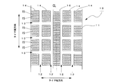
- FIG. 1 is a view showing an example of a tread pattern of a tire 10 according to the present embodiment, and FIG.
- the tread 11 is defined by a circumferential groove 12 formed so as to extend along the tire circumferential direction, a lateral groove 13 extending along a direction intersecting the circumferential groove 12, and the circumferential groove 12 and the lateral groove 13.
- the plurality of blocks 14 and sipe 15 formed on the tire tread surface side of each block 14 are provided.
- 1 is a center line indicating the center of the tire 10 in the width direction.
- the sipe 15 is a 3D sipe that extends in the direction parallel to the tire width direction on the surface of the block 14 and changes its shape in the tire radial direction in a plane perpendicular to the tire width direction.
- the surface shape of the sipe 15 may be a straight line parallel to the tire width direction.
- the surface shape of the sipe 15 is a straight part 15m parallel to the tire width direction.
- a trapezoidal wave shape having a slope portion 15n inclined with respect to the tire width direction.
- each of the sipe 15 is a 3D sipe having first and second bent portions P 2 and P 3 in the tire radial direction, and an opening to the surface 14k of the block 14 is provided.
- a first inclined portion 15p that terminates the sipe top P 1 is an end in the first bent portion P 2 is inclined linearly with respect to the tire radial direction as a start
- the first bent portion P 2 the first inclined portion 15p and the second inclined portion 15q terminating at the second bent portion P 3 inclined in the opposite direction as the starting end
- a third inclined portion 15r to terminate the sipe bottom P 4 is a tire radial direction innermost of the sipe 15.
- sipe center lines l 1 to l 6 which are straight lines connecting the sipe uppermost part P 1 and the sipe lowermost part P 4 , are inclined with respect to the tire radial direction which is the vertical direction of the figure. ing.
- the angles ⁇ and ⁇ formed by the center lines l 1 to l 6 of the sipes 151 to 156 and the tire radial direction are referred to as radial inclination angles.
- sipes (hereinafter referred to as end side sipes) 151 and 156 located on the tire circumferential direction end P side and end Q side of the block 14 and sipes located on the block central side (hereinafter referred to as the center side).
- the sipes 152 to 155 are both inclined in the direction from the one end P toward the other end Q with respect to the tire radial direction, and the radial inclination angle ⁇ of the end side sipes 151 and 156 is increased.
- the sipes 151 to 156 are formed so as to be larger than the radial inclination angle ⁇ of the central sipes 152 to 155.
- the direction in which the sipe falls (here, the direction from the end portion P toward the end portion Q) is hereinafter referred to as the sipe center line inclination direction.
- the inclination direction of the first and third inclined portions 15p, 15r of the end side sipes 151, 156 is the tire radial direction
- the first and third of the center side sipes 152-155 are The inclination direction of the third inclined portions 15p and 15r is set to be opposite to the inclination direction of the sipe center line.
- FIGS. 4A and 4B are views showing a state in which the block 14 is deformed on ice.
- FIG. 4A when there is an input F i from the same direction as the inclination direction of the sipe center line, the small blocks 141 and 147 on the input / output side float up because there are no blocks next to themselves, The contact area is lost.
- the radial inclination angle ⁇ of the end-side sipes 151 and 156 that define the small blocks 141 and 147 is increased, the collapse restraining moment of the small blocks 141 and 147 can be increased. .
- the contact performance of the tire can be improved.
- the radial inclination angle ⁇ of the end-side sipes 151 and 156 is increased as shown in this example. It is preferable to reduce the radial inclination angle ⁇ of the side sipes 152 to 155.
- the end portion P side of the small block 141 of the end-side sipe 151 Acts on the small block 141 from the end portion P side to the end portion Q side, and a moment M i is applied to lift the small block 141 from the road surface R.
- the small block 142 on the side opposite to the end P side of the sipe 151 is moved from the end P side to the end Q side, and the small block 142 is moved by the force F g from the road surface R. moment M g to topple the road surface R side acts.
- the cancel the moment M i and the moment M g, the small block 141 is deformed to fall on the end Q side from an end portion P side.
- the reduction of the contact area can be suppressed.
- FIG. 5B when there is an input F j to the block 14 from the other end Q side, the small block 147 on the end Q side of the end side sipe 156 has a small size. A moment M j is applied to cause the block 147 to fall from the end Q side to the end P side and to rise from the road surface R.
- the small block 146 on the side opposite to the end Q side of the sipe 151 is moved from the end Q side to the end P side, and the small block 146 is moved by the force F g from the road surface R. moment M g to topple the road surface R side acts.
- the walls (small block 147 and small block 146) on both sides of the second inclined portion 15q of the end side sipe 156 come into contact with each other, so that the small block 147 falls from the end Q side to the end P side. Transforms into Thereby, since the lift from the road surface of the small block 147 is suppressed, the reduction of the contact area can be suppressed.
- the end-side sipes 151, 156 are arranged so that the radial inclination angle ⁇ of the end-side sipes 151, 156 is larger than the radial inclination angle ⁇ of the central-side sipes 152-156.
- the center side sipes 152 to 155 the edge effect can be enhanced by the end side sipes 151 and 156, and the ground side area can be secured by the center side sipes 152 to 155. Both the ground contact performance and the on-ice performance of the tire can be improved.
- the inclination direction of the first inclined portion 15p which is the inclined portion on the tire tread surface side of each sipe 151 to 156, is opposite to the inclination direction of the sipe center line.
- the distance between the center of gravity of the small blocks 141 to 147 partitioned by the sipes 151 to 156 and the point of action of the lifting force is shortened, so that the moment in the lifting direction acting on the small blocks 141 to 147 can be reduced. . Therefore, since the reduction of the contact area when the tire 14 is input in the tire circumferential direction can be effectively suppressed, the contact performance of the tire can be further improved while ensuring the performance on ice.
- the inclination direction of the first and third inclined portions 15p and 15r of the sipes 151 to 156 and the inclination direction of the sipe center lines l 1 to l 6 are set in the tire radial direction.
- the inclination direction of the second inclined portion 15q and the inclination directions l 1 to l 6 of the sipe center line are opposite to the tire radial direction l 0 , as shown in FIG.
- the inclination directions of the first to third inclined portions 15p to 15r and the inclination directions of the sipe center lines l 1 and l 6 are the same as the tire radial direction.
- the inclination direction of the first and third inclined portions 15p and 15r and the inclination direction of the sipe center lines l 2 to l 5 are opposite to the tire radial direction.
- the inclination direction of the second inclined portion 15q and the inclination direction of the sipe center line If l 2 to l 5 are set in the same direction as the tire radial direction l 0 , the ground contact effect can be further improved. That is, since the contribution rate of the grounding effect is higher than the contribution rate of the edge effect in the ABS speed region on ice, when the input from the right side is assumed, the first to third as shown in FIG.
- the central portion to be supported has a small block on both sides, as shown in FIG.
- the sipe 151 to 156 are all inclined in the same direction.
- the sipe 151 to 156 is inclined with respect to the tire circumferential center of the block 14. May be symmetrical.
- the functions of the sipes 151 to 153 on the right side and the sipes 154 to 156 on the right side from the center of the block 14 are different depending on the input direction.
- FIG. 8B when the input from the right side is assumed, the small block 147 on the input / output side can obtain a floating suppression effect due to the shape effect due to the inclination of the entire small block 147.
- the shape effect and the sipe contact force due to the inclination of the small block 141 at that portion.
- the contact area can be improved.
- the edge part sipe 151,156 was arrange
- the inclination angle ⁇ of the side sipe 151 or the end side sipe 156) is made larger than the inclination angle ⁇ of the center side sipes 152 to 155, and the sipe (end side sipe 156 or end side sipe 151) on the kicking end side is set. ) Can be made the same as the inclination angle ⁇ of the central sipes 152 to 155, it is possible to suppress a sufficient decrease in the contact area.
- the tread pattern of the tire 10 was made into the block pattern, as shown in FIG. 9, the tread pattern which has the rib-shaped land part 16 in the tire width direction center may be sufficient, for example.
- the end-side sipes 151 and 156 and the central-side sipes 152 to 155 are sipes whose sipe center lines are inclined with respect to the tire radial direction, as shown in FIG.
- the center side sipes 152 to 155 are sipes (sipes facing the tire radial direction) having a radial inclination angle ⁇ of 0 °. There may be. Further, as shown in FIG.
- only the end side sipes 151 and 156 of the plurality of sipes 151 to 156 are 3D sipes having bent portions P 2 and P 3 in the tire radial direction, and other sipes
- the central sipes 152 to 155 may be 2D sipes.
- the end-side sipes 151 and 156 and the center-side sipes 152 to 155 are both sipes having at least two bent portions in the tire radial direction. Even if the sipe does not have a bent portion in the tire radial direction and the sipe 152 to 156 other than the end side sipe 151 has a sipe having at least two bent portions in the tire radial direction, the lift of the small block is effectively suppressed.
- the end-side sipe 156 may be a sipe having no bent portion in the tire radial direction, and the sipes 151 to 155 other than the end-side sipe 156 may be sipe having at least two bent portions in the tire radial direction. If there is a sipe at the center position of the block 14, for example, as shown in FIG. 11 (a), the sipe 163 located at the center position of the block 14 among the plurality of sipes 161 to 165 is replaced with the sipe center. It is good also as a flat sipe which does not have a bending part in a tire radial direction whose direction of a line is a tire radial direction.
- the surface shape of the sipe 163 may be a zigzag shape or a 2D sipe having a linear portion parallel to the tire width direction and a slope portion inclined with respect to the tire width direction, similar to the above embodiment. .
- the arrangement of the sipes 161 to 165 is axisymmetric with respect to the center position of the block 14 indicated by the thick dashed-dotted line c in FIG.
- the sipes 164 positioned at the center of the block 14 and the sipes 163 and 165 adjacent to the sipes 164 are replaced by flat sipes. That's fine.
- the sipe 163 located at a position closest to the center position of the block 14 indicated by a thick one-dot chain line c in FIG. 164 may be a flat sipe or a 2D sipe.
- the sipes 161 to 166 are preferably provided symmetrically with respect to the center position of the block 14.
- the radial inclination angle ⁇ of the end-side sipes 151 and 156 is larger than the radial inclination angle ⁇ of the central-side sipes 152 to 156.
- the region on the end side of the block 14 is the end region, and the remaining two regions are the central region.
- the average value of the absolute value of the radial inclination angle of the sipe in the end region may be larger than the average value of the absolute value of the radial inclination angle of the sipe in the central region.
- the average absolute value of the radial inclination angles is used instead of the average radial inclination angle.
- the sipe 15 is a 3D sipe extending in a direction parallel to the tire width direction, but the sipe 18 extending in a direction parallel to the tire circumferential direction as shown in FIG. (181 to 186) may be used.
- the sipes 181 to 186 are set so that the radial inclination angles of the tire end side sipes 181 and 186 are larger than the radial inclination angles of the central sipes 182 to 186. What is necessary is just to form.
- the block 14 has an input parallel to the tire width direction such as lateral force, it is possible to effectively prevent the small blocks defined by the sipes 181 to 186 from lifting from the road surface.
- FIG. 13 (b) if a sipe 19 extending in a direction intersecting the tire circumferential direction and the tire width direction is provided, the small sized by the sipe 19 with respect to input from multiple directions. Lifting of the block from the road surface can be effectively suppressed.
- the absolute value of the radial inclination angle of one and the other sipe of the sipe located on the tire circumferential direction end side of the block 14 is the diameter of the sipe other than the one and the other sipe.
- the sipe 18 and sipe 19 are 2D sipe having a linear surface shape.
- the surface shape is a trapezoidal 3D. It may be a sipe.
- the sipe 15 of the above-described embodiment has the rib-like land portion 16 (or the rib-like land portion 16 partitioned by a transverse groove) that contributes to the edge effect on the longitudinal force such as the brake.
- the sipe 18 is in the shoulder block 14C contributing to the edge effect on the lateral force
- the sipe 19 is in the intermediate block 14B disposed between the rib-like land portion 16 and the shoulder block 14C. It is preferable to provide it. Thereby, it can suppress effectively that the small block divided by the sipe 15,18,19 of the rib-shaped land part 16 and each block 14B, 14C lifts from a road surface. Therefore, the ground contact performance of the tire can be effectively improved while ensuring the performance on ice not only for the longitudinal force but also for the lateral force.
- the present invention provides an absolute value of the radial inclination angle of one of the sipe and the other sipe located on the circumferential end portion side or the tire width direction end portion side of the block.
- the value is larger than the absolute value of the radial inclination angle of the sipe other than the one and the other sipe.
- the other sipe is a sipe having at least two bent portions in the tire radial direction, it is possible to effectively prevent the small block from rising even in the reverse direction.
- the sipe other than the one sipe or the other sipe is a sipe having at least two bent portions in the tire radial direction, effectively suppressing the lifting of the small block, The ground contact performance and on-ice performance of the tire can be improved. Further, if all of the plurality of sipes are sipes having at least two bent portions in the tire radial direction, the ground contact performance and on-ice performance of the tire can be further improved.
- any one or both of the sipe located at the center position of the block and the sipe located closest to the center position of the block among the plurality of sipes are sipe center lines.
- the direction is the tire radial direction, and the 2D sipe does not have a bent portion in the tire radial direction.
- a blade having a simple structure can be used for a sipe in the vicinity of the center of the block that has little contribution to the floating of the small block, and therefore, it is easy to manufacture a tire having excellent ground contact performance and on-ice performance.
- even if only one of the plurality of sipes has at least two bent portions in the tire radial direction it is possible to effectively suppress the lift of the small blocks, so that The performance on ice can be improved.
- the present invention is characterized in that the plurality of sipes are inclined in the same direction, or inclined toward the end in the circumferential direction or the end in the tire width direction of the block closer to the center position of the block. And
- the sipe is formed so that the bottom of the sipe is closer to the block end than the top of the sipe (opening end) so that the reverse of the sipe It can be demonstrated. Therefore, the ground contact performance and the on-ice performance of the tire can be reliably improved.
- the block is divided into four in a direction perpendicular to the extending direction of the sipe, one or the other end side region of the block is an end side region, and the remaining two regions are a central region.
- the average value of the absolute values of the radial inclination angles of the sipe in the end region is set larger than the average value of the absolute values of the radial inclination angles of the sipe in the central region.
- the absolute value of the absolute value of the radial inclination angle in the end region is not the absolute value of the radial inclination angle of each sipe, but the average value of the absolute value of the radial inclination angle in the central region.
- the present invention is characterized in that the absolute value of the radial inclination angle of the plurality of sipes is larger as the sipes provided closer to the end of the block and smaller as the sipes provided closer to the center position. And thereby, since the rigidity of the edge part which is easy to deform
- the present invention is a tire including a circumferential groove, a lug groove, a plurality of blocks defined by the circumferential groove and the lug groove, and a plurality of sipes provided in the block,
- the plurality of sipes extend from the tire center portion side of the block in which the sipes are formed to the end portion in the tread width direction while being inclined with respect to the tire circumferential direction and the tire width direction.
- One and the other sipes of the sipe located on the circumferential end side of the block are straight lines connecting the sipe uppermost part that is an open end to the block surface and the sipe lowermost part that is the innermost part in the tire radial direction.
- a certain sipe center line is inclined with respect to the tire radial direction, and when an angle formed between the sipe center line and the tire radial direction is a radial inclination angle, an absolute value of the radial inclination angle of the one sipe is The absolute value of the radial inclination angle of the other sipe is larger than the absolute value of the radial inclination angle of the other sipe, and the absolute value of the radial inclination angle of the sipe other than the one and the other sipe Is also large.
- the sipe center line of the sipe that is inclined and extended with respect to the tire circumferential direction and the tire width direction from the tire center portion side of the block to the tread width direction end portion side is inclined with respect to the tire radial direction. Therefore, the lift of the small block can be suppressed both for the input from the tire circumferential direction and the input from the tire width direction.
Landscapes
- Engineering & Computer Science (AREA)
- Mechanical Engineering (AREA)
- Tires In General (AREA)
Abstract
タイヤの接地性能と氷上性能とをともに向上させるために、トレッド表面に形成された複数のブロック(14)のタイヤ踏面側に、ブロック(14)の周方向端部側に位置するサイプ(151)もしくはサイプ(156)の少なくとも一方もしくは両方のサイプを、タイヤ径方向に少なくとも2ヶ所の屈曲部(P2,P3)を有し、かつブロック(14)の表面(14k)への開口端であるサイプ最上部(P1)とタイヤ径方向最内部であるサイプ最下部(P4)とを結ぶ直線であるサイプ中心線(ln:n=1~6)がタイヤ径方向に対して傾斜したサイプ複数のサイプ(151~156)を形成するとともに、ブロック(14)の周方向端部側に位置するサイプ(151,156)のサイプ中心線とタイヤ径方向とのなす角度である径方向傾斜角(α)の絶対値が、中央部に位置するサイプ(152~155)の径方向傾斜角(β)の絶対値よりも大きくなるように、サイプ(151~156)を形成した。
Description
本発明は、トレッド陸部のタイヤ踏面側に3Dサイプが形成されたタイヤに関するもので、特に、氷路面において優れた走行性能を有するタイヤに関する。
従来、スタッドレスタイヤのトレッドパターンとして、氷上走行性能を向上させるため、周方向溝に交差する方向に延長するラグ溝を設けるとともに、周方向溝とラグ溝とにより区画されたブロック状陸部の表面にタイヤ幅方向に延長するサイプを形成したものが多く用いられている。
しかしながら、上記の構成では、氷上性能は向上するものの、ブロック状陸部の剛性が低下するため接地性が低下するおそれがあった。そこで、サイプを、タイヤ踏面側だけでなく、タイヤ径方向にも形状を変化させた3Dサイプとすることで、サイプにより細分化された陸部同士を接触させてブロック状陸部の剛性の低下を抑制する方法が提案されている(例えば、特許文献1参照)。
しかしながら、上記の構成では、氷上性能は向上するものの、ブロック状陸部の剛性が低下するため接地性が低下するおそれがあった。そこで、サイプを、タイヤ踏面側だけでなく、タイヤ径方向にも形状を変化させた3Dサイプとすることで、サイプにより細分化された陸部同士を接触させてブロック状陸部の剛性の低下を抑制する方法が提案されている(例えば、特許文献1参照)。
しかしながら、サイプを3Dサイプとしただけでは、ブロック状陸部の変形が抑制されるため、サイプが開きにくくなり、エッジ効果が低減してしまうといった問題点があった。
本発明は、従来の問題点に鑑みてなされたもので、タイヤの接地性能と氷上性能とをともに向上させることができるタイヤを提供することを目的とする。
本発明は、トレッド表面にタイヤ周方向に沿って延長するように形成された周方向溝と、前記周方向溝と交差する方向に延長するラグ溝と、前記周方向溝と前記ラグ溝とにより区画される複数のブロックと、前記ブロックに設けられる複数のサイプとを備えたタイヤであって、前記複数のサイプは、当該サイプの形成されているブロックの表面では、タイヤ幅方向またはタイヤ周方向のいずれかの方向にのみに延長し、前記複数のサイプのうちの前記ブロックの周方向端部側またはタイヤ幅方向端部側に位置するサイプの少なくとも一方のサイプは、前記ブロック表面への開口端であるサイプ最上部とタイヤ径方向最内部であるサイプ最下部とを結ぶ直線であるサイプ中心線がタイヤ径方向に対して傾斜しており、前記サイプ中心線とタイヤ径方向とのなす角度を径方向傾斜角としたとき、前記一方のサイプの径方向傾斜角の絶対値が、前記一方のサイプ以外のサイプの径方向傾斜角の絶対値よりも大きいことを特徴とする。
このように、ブロックのタイヤ周方向端部側またはタイヤ幅方向端部側に位置するサイプ(複数のサイプが全てタイヤ幅方向方向に延長するサイプなら、ブロックの周方向端部側に位置するサイプ,複数のサイプが全てタイヤ周方向に延長するサイプなら、ブロックの幅方向端部側に位置するサイプ)の少なくとも一方のサイプのサイプ中心線をタイヤ径方向に対して傾斜させたので、端部側に位置するサイプにより区画された端部側の小ブロックの浮き上がりを抑制することができ、接地効果を高めることができる。また、端部の少なくとも一方の側ではサイプを寝かせ、他の領域ではサイプを立たせることで、逆方向入力の際の接地効果の低下を抑えるようにしたので、タイヤの接地性能と氷上性能とをともに向上させることができる。
ここで、タイヤ周方向端部側またはタイヤ幅方向端部側に位置するサイプとは、タイヤ周方向に沿って設けられたタイヤ幅方向に延長する複数のサイプのうちのタイヤ周方向端部に最も近い位置に設けられたサイプ、または、タイヤ幅方向に沿って設けられたタイヤ周方向に延長する複数のサイプのうちの、タイヤ幅方向端部に最も近い位置に設けられたサイプを意味するが、当該ブロックに設けられたサイプが多数あるときには、前記最も近い位置に設けられたサイプとこのサイプに隣接する複数のサイプ(例えば、サイプが6本の場合には、端部に最も近い位置に設けられたサイプと2番目に近い位置に設けられたサイプ)も「端部側に位置するサイプ」に含まれるものとする。
なお、前記発明の概要は、本発明の必要な全ての特徴を列挙したものではなく、これらの特徴群のサブコンビネーションもまた、発明となり得る。
以下、本発明の実施の形態について、図面に基づき説明する。
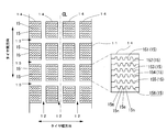
図1は本実施の形態に係るタイヤ10のトレッドパターンの一例を示す図、図2はトレッド11の要部斜視図である。
トレッド11は、タイヤ周方向に沿って延長するように形成された周方向溝12と、周方向溝12に交差する方向に沿って延長する横溝13と、周方向溝12と横溝13とにより区画された複数のブロック14と、各ブロック14のタイヤ踏面側にそれぞれ形成されたサイプ15とを備える。なお、図1の符合CLはタイヤ10の幅方向中心を示すセンターラインである。
サイプ15は、ブロック14の表面においてはタイヤ幅方向に平行な方向に延長し、タイヤ幅方向に垂直な面内においてはタイヤ径方向に形状を変化させた3Dサイプである。
サイプ15の表面形状としては、タイヤ幅方向に平行な直線状であってもよいが、本例では、図1に示すように、サイプ15の表面形状を、タイヤ幅方向に平行な直線部15mとタイヤ幅方向に対して傾斜する斜面部15nとを有する台形波状としている。これにより、タイヤ周方向だけでなく、タイヤ幅方向にもエッジ成分を持たせることができるので、氷上走行時の操縦安定性能を向上させることができる。
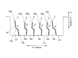
図3に示すように、サイプ15(151~156)は、いずれも、タイヤ径方向に第1及び第2の屈曲部P2,P3を有する3Dサイプで、ブロック14の表面14kへの開口端であるサイプ最上部P1を始端としてタイヤ径方向に対して直線状に傾斜して第1の屈曲部P2にて終端する第1の傾斜部15pと、第1の屈曲部P2を始端として第1の傾斜部15pとは反対方向に傾斜して第2の屈曲部P3にて終端する第2の傾斜部15qと、第2の屈曲部P3を始端として第1の傾斜部15pと同方向に傾斜して当該サイプ15のタイヤ径方向最内部であるサイプ最下部P4を終端とする第3の傾斜部15rとを備える。
また、サイプ151~156は、サイプ最上部P1とサイプ最下部P4とを結ぶ直線であるサイプ中心線l1~l6が、同図の上下方向であるタイヤ径方向に対して傾斜している。
以下、サイプ151~156の中心線l1~l6とタイヤ径方向とのなす角度α,βを径方向傾斜角という。
本例では、ブロック14のタイヤ周方向端部P側及び端部Q側に位置するサイプ(以下、端部側サイプという)151,156、及び、ブロック中央側に位置するサイプ(以下、中央側サイプという)152~155を、ともに、タイヤ径方向に対して、一方の端部Pから他方の端部Qに向かう方向に傾斜させるとともに、端部側サイプ151,156の径方向傾斜角αを中央側サイプ152~155の径方向傾斜角βよりも大きくなるように各サイプ151~156を形成した。なお、サイプが倒れていく方向(ここでは、端部Pから端部Qに向かう方向)を、以下、サイプ中心線の傾き方向という。
本例では、図3に示すように、端部側側サイプ151,156の第1及び第3の傾斜部15p,15rの傾き方向をタイヤ径方向とし、中央側サイプ152~155の第1及び第3の傾斜部15p,15rの傾き方向をサイプ中心線の傾き方向と逆方向になるようにしている。
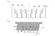
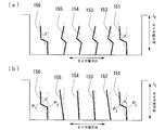
図4(a),(b)は、ブロック14が氷上で変形している様子を示す図である。
図4(a)に示すように、サイプ中心線の傾き方向と同じ方向から入力Fiがあった場合、入力出側の小ブロック141,147は自身の隣にブロックがいないため浮き上がってしまい、接地面積を失ってしまう。しかしながら、本例では、小ブロック141,147を区画する端部側サイプ151,156の径方向傾斜角αを大きくしているので、小ブロック141,147の倒れこみ抑制モーメントを大きくすることができる。したがって、小ブロック141,147の浮き上がりを抑制して、接地面積を確保することができるので、タイヤの接地性能を向上させることができる。
一方、サイプ151~156の傾斜角度を全て大きくしてしまうと、図4(b)に示すように、サイプ中心線の傾き方向と反対方向から入力Fjがあった場合に、浮き上がり方向のモーメントが発生してしまい、接地面積を大きく失ってしまうことになる。
したがって、どちらの方向から入力があっても、小ブロックの浮き上りがないようにするためには、本例のように、端部側サイプ151,156の径方向傾斜角αを大きくし、中央側サイプ152~155の径方向傾斜角βを小さくすることが好ましい。
具体的には、図5(a)に示すように、一方の端部P側からブロック14に入力Fiがあった場合には、端部側サイプ151の端部P側の小ブロック141には、小ブロック141を端部P側から端部Q側に倒すとともに路面Rから浮き上がらせようとするモーメントMiが作用する。また、サイプ151の端部P側とは反対側の小ブロック142には、小ブロック142を端部P側から端部Q側に移動させるとともに、路面Rからの力Fgによって小ブロック142を路面R側に倒そうとするモーメントMgが作用する。その結果、モーメントMiとモーメントMgと打ち消し合うので、小ブロック141は、端部P側から端部Q側に倒れるように変形する。これにより、小ブロック141の路面Rから浮き上がりは抑制されるので、接地面積の減少を抑制することができる。
また、図5(b)に示すように、他方の端部Q側からブロック14に入力Fjがあった場合には、端部側サイプ156の端部Q側の小ブロック147には、小ブロック147を端部Q側から端部P側に倒すとともに路面Rから浮き上がらせようとするモーメントMjが作用する。また、サイプ151の端部Q側とは反対側の小ブロック146には、小ブロック146を端部Q側から端部P側に移動させるとともに、路面Rからの力Fgによって小ブロック146を路面R側に倒そうとするモーメントMgが作用する。その結果、端部側サイプ156の第2の傾斜部15qの両側の壁(小ブロック147と小ブロック146)が当接するので、小ブロック147は、端部Q側から端部P側に倒れるように変形する。これにより、小ブロック147の路面から浮き上がりは抑制されるので、接地面積の減少を抑制することができる。
また、図5(b)に示すように、他方の端部Q側からブロック14に入力Fjがあった場合には、端部側サイプ156の端部Q側の小ブロック147には、小ブロック147を端部Q側から端部P側に倒すとともに路面Rから浮き上がらせようとするモーメントMjが作用する。また、サイプ151の端部Q側とは反対側の小ブロック146には、小ブロック146を端部Q側から端部P側に移動させるとともに、路面Rからの力Fgによって小ブロック146を路面R側に倒そうとするモーメントMgが作用する。その結果、端部側サイプ156の第2の傾斜部15qの両側の壁(小ブロック147と小ブロック146)が当接するので、小ブロック147は、端部Q側から端部P側に倒れるように変形する。これにより、小ブロック147の路面から浮き上がりは抑制されるので、接地面積の減少を抑制することができる。
ところで、端部側サイプ151,156の径方向傾斜角αと中央側サイプ152~155の径方向傾斜角βとを同じ角度とした場合には、径方向傾斜角が大きい場合には、エッジ効果は増大するが、タイヤ径方向におけるサイプ151~156Bの接触が十分でないため、ブロック14が変形しやすくなり、その結果、接地性能を十分確保できないおそれがある。逆に、径方向傾斜角が小さい場合には、接地性能は確保できるがエッジ効果はあまり増大しない。
これに対して、本例では、端部側サイプ151,156の径方向傾斜角αを中央側サイプ152~156の径方向傾斜角βよりも大きくなるように、端部側サイプ151,156と中央側サイプ152~155とを形成することで、端部側サイプ151,156によりエッジ効果を高めることができるとともに、中央側サイプ152~155により、接地面積を確保することができるようにしたので、タイヤの接地性能と氷上性能とをともに向上させることができる。
また、本例では、各サイプ151~156のタイヤ踏面側の傾斜部である第1の傾斜部15pの傾き方向をサイプ中心線の傾き方向と逆方向にしている。これにより、サイプ151~156により区画された小ブロック141~147の重心と浮き上がり力の作用点との距離が短くなるので、小ブロック141~147に作用する浮き上がり方向のモーメントを小さくすることができる。したがって、ブロック14にタイヤ周方向の入力があった場合の接地面積の減少を効果的に抑制することができるので、氷上性能を確保しつつ、タイヤの接地性能を更に向上させることができる。
以上、本発明を実施の形態を用いて説明したが、本発明の技術的範囲は前記実施の形態に記載の範囲には限定されない。前記実施の形態に、多様な変更または改良を加えることが可能であることが当業者にも明らかである。そのような変更または改良を加えた形態も本発明の技術的範囲に含まれ得ることが、特許請求の範囲から明らかである。
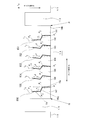
例えば、前記実施の形態では、図3に示すように、サイプ151~156の第1及び第3の傾斜部15p,15rの傾斜方向とサイプ中心線l1~l6の傾斜方向をタイヤ径方向に対して同方向とし、第2の傾斜部15qの傾斜方向とサイプ中心線の傾斜方向l1~l6をタイヤ径方向l0に対して反対方向としたが、図6に示すように、端部側サイプ151,156では、第1~第3の傾斜部15p~15rの傾斜方向とサイプ中心線l1,l6の傾斜方向とをタイヤ径方向に対して同方向とし、中央側サイプ152~155では、前記実施の形態と同様に、第1及び第3の傾斜部15p,15rの傾斜方向とサイプ中心線l2~l5の傾斜方向をタイヤ径方向に対して反対方向とし、第2の傾斜部15qの傾斜方向とサイプ中心線の傾斜方向l2~l5を、タイヤ径方向l0に対して同方向とすれば、接地効果を更に向上させることができる。
すなわち、氷上ABS速度領域では接地効果の寄与率がエッジ効果の寄与率よりも高いことから、右側からの入力を想定した場合には、図7(a)に示すような、第1~第3の傾斜部15p~15rの傾斜方向とサイプ中心線lnの傾斜方向とが全てタイヤ径方向に対して同方向であるサイプ15Aを用いたほうが、形状効果をより大きく発揮できる。したがって、浮き上がりによる接地面積損失の大きい入力出側端部に、サイプ15Aを用いることで接地面積低下を効果的に抑制することができる。
一方、全てのサイプをサイプ15Aとすると、逆(左側からの)入力の場合に形状効果が逆に浮き上がり方向に働いてしまい接地面積の低下が大きくなってしまう。そこで、両側に小ブロックがあり支えられる中央部は、図7(b)に示すような、第1及び第3の傾斜部15p,15rの傾斜方向がサイプ中心線lnの傾斜方向と反対であるようなサイプ15Bを用いることで、形状効果を小さくし、接触力で浮き上がり抑制を行えば、両方からの入力に対して、接地効果を確実に発揮させることができる。
また、前記実施の形態では、サイプ151~156の傾斜方向を全て同じ向きにしたが、図8(a)に示すように、サイプ151~156の傾斜方向をブロック14のタイヤ周方向中心に対して対称になるようにしてもよい。この場合には、ブロック14のセンターから右側のサイプ151~153と左側のサイプ154~156とでは、入力の方向により機能が異なる。例えば、図8(b)に示すように、右側からの入力を想定した場合、入力出側の小ブロック147に関しては、小ブロック147全体の傾斜による形状効果による浮き上がり抑制効果が得られる。一方、入力入側の小ブロック141に関してはサイプ151の接触部以下に着目し、その部分の小ブロック141の傾斜による形状効果とサイプ接触力(小ブロック141と小ブロック142との接触力)で浮き上がりを抑制することで、接地面積の向上を実現できる。
また、前記実施の形態では、ブロック14の周方向端部両端側に端部側サイプ151,156を配置したが、タイヤ10が方向性タイヤである場合には、踏み込み端側のサイプ(端部側サイプ151または、端部側サイプ156)の傾斜角αのみを中央側サイプ152~155の傾斜角βより大きくし、蹴り出し端側のサイプ(端部側サイプ156または、端部側サイプ151)の傾斜角αを中央側サイプ152~155の傾斜角βと同じにしても、十分な接地面積の低下を抑制することができる。
また、前記実施の形態では、タイヤ10のトレッドパターンをブロックパターンとしたが、例えば、図9に示すように、タイヤ幅方向中心にリブ状陸部16を有するトレッドパターンであってもよい。
また、前記実施の形態では、端部側サイプ151,156と中央側サイプ152~155とを、サイプ中心線がタイヤ径方向に対して傾斜したサイプとしたが、図10(a)に示すように、中央側サイプ152~155(特に、ブロック14のタイヤ周方向中央部にあるサイプ153,154)については、径方向傾斜角βが0°であるサイプ(タイヤ径方向を向いたサイプ)であってもよい。
また、図10(b)に示すように、複数のサイプ151~156の内の、端部側サイプ151,156のみをタイヤ径方向に屈曲部P2,P3有する3Dサイプとし、他のサイプである中央側サイプ152~155を2Dサイプとしてもよい。
また、前記実施の形態では、端部側サイプ151,156と中央側サイプ152~155とを、ともに、タイヤ径方向に少なくとも2ヶ所の屈曲部を有するサイプとしたが、端部側サイプ151をタイヤ径方向に屈曲部を有しないサイプとし、端部側サイプ151以外のサイプ152~156を、タイヤ径方向に少なくとも2ヶ所の屈曲部を有するサイプとしても、小ブロックの浮き上がりを効果的に抑制して、タイヤの接地性能と氷上性能とを向上させることができる。また、端部側サイプ156をタイヤ径方向に屈曲部を有しないサイプとし、端部側サイプ156以外のサイプ151~155を、タイヤ径方向に少なくとも2ヶ所の屈曲部を有するサイプとしてもよい。
また、ブロック14の中心位置にサイプがある場合には、例えば、図11(a)に示すように、複数のサイプ161~165のうち、ブロック14の中心位置に位置するサイプ163を、サイプ中心線の向きがタイヤ径方向である、タイヤ径方向に屈曲部を有しない平板状のサイプとしてもよい。なお、サイプ163の表面形状については、ジグザグ状、もしくは、前記実施の形態と同様の、タイヤ幅方向に平行な直線部とタイヤ幅方向に対して傾斜する斜面部とを有する2Dサイプとしてもよい。このとき、サイプ161~165の配置としては、同図の太い一点鎖線cで示すブロック14の中心位置に対して線対称とすることが好ましい。
また、サイプ数が多い場合には、例えば、図11(b)に示すように、ブロック14の中心位置に位置するサイプ164とサイプ164に隣接するサイプ163及びサイプ165を平板状のサイプとすればよい。
また、ブロック14の中心位置にサイプがない場合には、例えば、図11(c)に示すように、同図の太い一点鎖線cで示すブロック14の中心位置に最も近い位置に位置するサイプ163,164を、平板状のサイプもしくは、2Dサイプとすればよい。この場合も、サイプ161~166は、ブロック14の中心位置に対して線対称に設けることが好ましい。
これにより、小ブロックの浮き上がりに対して寄与の少ないブロック中心近傍のサイプに簡単な構造のブレードを用いることができるので、接地性能と氷上性能とに優れたタイヤの製造が容易となる。
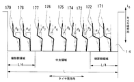
また、前記実施の形態では、端部側サイプ151,156の径方向傾斜角αを中央側サイプ152~156の径方向傾斜角βよりも大きくしたが、図12に示すように、ブロック14をサイプの延長方向と直交する方向(ここでは、タイヤ周方向)に4分割し、当該ブロック14の端部側の領域を端部側領域とし、残りの2つの領域を中央領域としたとき、前記端部側領域のサイプの径方向傾斜角の絶対値の平均値を、中央領域のサイプの径方向傾斜角の絶対値の平均値よりも大きくしてもよい。
例えば、一方の端部側領域のサイプをサイプ171,172、他方の端部側領域のサイプをサイプ178,179、中央領域のサイプをサイプ173~177、各サイプ17iの径方向傾斜角をθi(i=1~9)とすると、(θ1+θ2)/2>(θ2+θ3+θ4+θ5+θ6)/4、かつ、(θ8+θ9)/2>(θ2+θ3+θ4+θ5+θ6)/4である。
なお、サイプの傾斜方向が異なる場合には、径方向傾斜角の平均値ではなく、径方向傾斜角の絶対値の平均値を用いることはいうまでもない。
例えば、一方の端部側領域のサイプをサイプ171,172、他方の端部側領域のサイプをサイプ178,179、中央領域のサイプをサイプ173~177、各サイプ17iの径方向傾斜角をθi(i=1~9)とすると、(θ1+θ2)/2>(θ2+θ3+θ4+θ5+θ6)/4、かつ、(θ8+θ9)/2>(θ2+θ3+θ4+θ5+θ6)/4である。
なお、サイプの傾斜方向が異なる場合には、径方向傾斜角の平均値ではなく、径方向傾斜角の絶対値の平均値を用いることはいうまでもない。
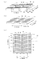
また、前記実施の形態では、サイプ15を、タイヤ幅方向に平行な方向に延長する3Dサイプとしたが、図13(a)に示すような、タイヤ周方向に平行な方向に延長するサイプ18(181~186)としてもよい。この場合には、サイプ181~186のうちの、タイヤ端部側サイプ181,186の径方向傾斜角を中央側サイプ182~186の径方向傾斜角よりも大きくなるように、サイプ181~186を形成すればよい。これにより、ブロック14に、横力などのタイヤ幅方向に平行な入力があった場合には、サイプ181~186により区画された小ブロックの路面からの浮き上がりを効果的に抑制することができる。
また、図13(b)に示すように、タイヤ周方向とタイヤ幅方向とに交差する方向に延長するサイプ19を設ければ、多方向からの入力に対して、サイプ19により区画された小ブロックの路面からの浮き上がりを効果的に抑制することができる。この場合には、サイプ19のうちの、ブロック14のタイヤ周方向端部側に位置するサイプの一方及び他方のサイプの径方向傾斜角の絶対値が、一方及び他方のサイプ以外のサイプの径方向傾斜角の絶対値よりも大きくすればよい。
なお、 図13(a),(b)では、サイプ18及びサイプ19を、表面形状が直線状の2Dサイプとしたが、前記実施の形態のサイプ15と同様に、表面形状が台形波状の3Dサイプとしてもよい。
また、図13(c)に示すように、前記実施の形態のサイプ15は、ブレーキなどの前後力に対するエッジ効果に寄与するリブ状陸部16(もしくは、リブ状陸部16を横溝で区画したセンターブロック)に、前記のサイプ18は、横力に対するエッジ効果に寄与するショルダーブロック14Cに、前記のサイプ19は、リブ状陸部16とショルダーブロック14Cとの間に配置される中間ブロック14Bに設けることが好ましい。
これにより、リブ状陸部16及び各ブロック14B,14Cの、サイプ15,18,19により区画された小ブロックが路面から浮き上がることを効果的に抑制することができる。したがって、前後力だけでなく横力に対しても、氷上性能を確保しつつ、タイヤの接地性能を効果的に向上させることができる。
また、上述したように、本発明は、前記複数のサイプのうちの前記ブロックの周方向端部側またはタイヤ幅方向端部側に位置するサイプの一方及び他方のサイプの径方向傾斜角の絶対値を、前記一方及び他方のサイプ以外のサイプの径方向傾斜角の絶対値よりも大きいことを特徴とする。
これにより、逆方向からの入力に対しても接地効果を確保できるので、タイヤの接地性能と氷上性能とを更に向上させることができる。
また、本発明は、前記一方のサイプは、タイヤ径方向に少なくとも2ヶ所の屈曲部を有することを特徴とする。
これにより、小ブロックの浮き上がりを効果的に抑制できるので、タイヤの接地性能と氷上性能とを向上させることができる。
また、他方のサイプを、タイヤ径方向に少なくとも2ヶ所の屈曲部を有するサイプとすれば、逆方向の入力に対しても、小ブロックの浮き上がりを効果的に抑制できる。
また、前記複数のサイプのうち、前記一方のサイプまたは他方のサイプ以外のサイプを、タイヤ径方向に少なくとも2ヶ所の屈曲部を有するサイプとしても、小ブロックの浮き上がりを効果的に抑制して、タイヤの接地性能と氷上性能とを向上させることができる。
また、前記複数のサイプを、全て、タイヤ径方向に少なくとも2ヶ所の屈曲部を有するサイプとすれば、タイヤの接地性能と氷上性能とを更に向上させることができる。
また、本発明は、前記複数のサイプのうち、前記ブロックの中心位置に位置するサイプ、及び、前記ブロックの中心位置に最も近い位置に位置するサイプのいずれか一方もしくは両方が、サイプ中心線の向きがタイヤ径方向であり、タイヤ径方向に屈曲部を有しない2Dサイプであることを特徴とする。
これにより、小ブロックの浮き上がりに対して寄与の少ないブロック中心近傍のサイプに簡単な構造のブレードを用いることができるので、接地性能と氷上性能とに優れたタイヤの製造が容易となる。
また、前記複数のサイプの内の、前記一方及び他方のサイプのみがタイヤ径方向に少なくとも2ヶ所の屈曲部を有するだけでも、小ブロックの浮き上がりを効果的に抑制できるので、タイヤの接地性能と氷上性能とを向上させることができる。
また、本発明は、前記複数のサイプが同じ方向に傾いているか、もしくは、当該ブロックの中心位置から近い方のブロックの周方向端部側またはタイヤ幅方向端部側に傾いていることを特徴とする。
すなわち、一方向からの入力が大きい場合には、複数のサイプを同じ方向に傾け、ブロックが傾斜等していて他方向から入力する場合には、中心位置に対して周方向または幅方向に傾きが逆になるように、かつ、サイプ最下部がサイプ最上部(開口端)よりブロック端部に近い位置になるように複数のサイプを形成したので、小ブロックの浮き上が抑制効果を確実に発揮することができる。したがって、タイヤの接地性能と氷上性能とを確実に向上させることができる。
また、本発明は、前記ブロックを前記サイプの延長方向と直交する方向に4分割し、前記ブロックの一方または他方の端部側の領域を端部側領域とし、残りの2つの領域を中央領域としたとき、前記端部側領域のサイプの径方向傾斜角の絶対値の平均値を、前記中央領域のサイプの径方向傾斜角の絶対値の平均値よりも大きくしたことを特徴とする。
このように、個々のサイプの径方向傾斜角の絶対値ではなく、端部側領域における径方向傾斜角の絶対値の平均値を中央領域における径方向傾斜角の絶対値の平均値よりも端部側領域で大きくしても、端部側の小ブロックの浮き上がりを抑制することができるので、タイヤの接地性能と氷上性能とを確実に向上させることができる。
また、本発明は、前記複数のサイプの径方向傾斜角の絶対値が、当該ブロックの端部に近い位置に設けられたサイプほど大きく中心位置に近い位置に設けられたサイプほど小さいことを特徴とする。
これにより、入力により変形しやすい端部の剛性を向上させることができるので、小ブロックの浮き上がりを効果的に抑制することができる。
また、本発明は、周方向溝と、ラグ溝と、前記周方向溝と前記ラグ溝とにより区画される複数のブロックと、前記ブロックに設けられる複数のサイプとを備えたタイヤであって、前記複数のサイプは、当該サイプの形成されているブロックのタイヤセンター部側からトレッドの幅方向端部側まで、タイヤ周方向及びタイヤ幅方向に対して傾斜して延長し、前記複数のサイプのうちの前記ブロックの周方向端部側に位置するサイプの一方及び他方のサイプは、前記ブロック表面への開口端であるサイプ最上部とタイヤ径方向最内部であるサイプ最下部とを結ぶ直線であるサイプ中心線がタイヤ径方向に対して傾斜しており、前記サイプ中心線とタイヤ径方向とのなす角度を径方向傾斜角としたとき、前記一方のサイプの径方向傾斜角の絶対値が、前記他方のサイプの径方向傾斜角の絶対値よりも大きく、かつ、前記他方のサイプの径方向傾斜角の絶対値が、前記一方及び他方のサイプ以外のサイプの径方向傾斜角の絶対値よりも大きいことを特徴とする。
このように、ブロックのタイヤセンター部側からトレッドの幅方向端部側まで、タイヤ周方向及びタイヤ幅方向に対して傾斜して延長するサイプのサイプ中心線をタイヤ径方向に対して傾斜させたので、タイヤ周方向からの入力に対しても、タイヤ幅方向からの入力に対しても、小ブロックの浮き上がりを抑制することができる。
このように、ブロックのタイヤセンター部側からトレッドの幅方向端部側まで、タイヤ周方向及びタイヤ幅方向に対して傾斜して延長するサイプのサイプ中心線をタイヤ径方向に対して傾斜させたので、タイヤ周方向からの入力に対しても、タイヤ幅方向からの入力に対しても、小ブロックの浮き上がりを抑制することができる。
10 タイヤ、11 トレッド、12 周方向溝、13 横溝、
14 ブロック、15,151~156 サイプ、15m 直線部、
15n 斜面部、15p 第1の傾斜部、15q 第2の傾斜部、
15r 第3の傾斜部、16 リブ状陸部。
14 ブロック、15,151~156 サイプ、15m 直線部、
15n 斜面部、15p 第1の傾斜部、15q 第2の傾斜部、
15r 第3の傾斜部、16 リブ状陸部。
Claims (10)
- トレッド表面にタイヤ周方向に沿って延長するように形成された周方向溝と、前記周方向溝と交差する方向に延長するラグ溝と、前記周方向溝と前記ラグ溝とにより区画される複数のブロックと、前記ブロックに設けられる複数のサイプとを備えたタイヤであって、
前記複数のサイプは、当該サイプの形成されているブロックの表面では、タイヤ幅方向またはタイヤ周方向のいずれかの方向にのみに延長し、
前記複数のサイプのうちの前記ブロックの周方向端部側またはタイヤ幅方向端部側に位置するサイプの少なくとも一方のサイプは、前記ブロック表面への開口端であるサイプ最上部とタイヤ径方向最内部であるサイプ最下部とを結ぶ直線であるサイプ中心線がタイヤ径方向に対して傾斜しており、
前記サイプ中心線とタイヤ径方向とのなす角度を径方向傾斜角としたとき、
前記一方のサイプの径方向傾斜角の絶対値が、前記一方のサイプ以外のサイプの径方向傾斜角の絶対値よりも大きいことを特徴とするタイヤ。 - 前記複数のサイプのうちの前記ブロックの周方向端部側またはタイヤ幅方向端部側に位置するサイプの一方及び他方のサイプの径方向傾斜角の絶対値が、前記一方及び他方のサイプ以外のサイプの径方向傾斜角の絶対値よりも大きいことを特徴とする請求項1に記載のタイヤ。
- 前記一方のサイプは、タイヤ径方向に少なくとも2ヶ所の屈曲部を有することを特徴とする請求項1に記載のタイヤ。
- 前記他方のサイプは、タイヤ径方向に少なくとも2ヶ所の屈曲部を有することを特徴とする請求項2に記載のタイヤ。
- 前記複数のサイプのうち、前記一方のサイプまたは他方のサイプ以外のサイプが、タイヤ径方向に少なくとも2ヶ所の屈曲部を有することを特徴とする請求項3または請求項4に記載のタイヤ。
- 前記複数のサイプが、全て、タイヤ径方向に少なくとも2ヶ所の屈曲部を有することを特徴とする請求項3または請求項4に記載のタイヤ。
- 前記複数のサイプのうち、前記ブロックの中心位置に位置するサイプ、及び、前記ブロックの中心位置に最も近い位置に位置するサイプのいずれか一方もしくは両方が、サイプ中心線の向きがタイヤ径方向であり、タイヤ径方向に屈曲部を有しない2Dサイプであることを特徴とする請求項3または請求項4に記載のタイヤ。
- 前記複数のサイプの内の、前記一方及び他方のサイプのみがタイヤ径方向に少なくとも2ヶ所の屈曲部を有することを特徴とする請求項3または請求項4に記載のタイヤ。
- 前記複数のサイプが同じ方向に傾いているか、もしくは、当該ブロックの中心位置から近い方のブロックの周方向端部側またはタイヤ幅方向端部側に傾いていることを特徴とする請求項1または請求項2に記載のタイヤ。
- 前記ブロックを前記サイプの延長方向と直交する方向に4分割し、当該ブロックの一方または他方の端部側の領域を端部側領域とし、残りの2つの領域を中央領域としたとき、
前記端部側領域のサイプの径方向傾斜角の絶対値の平均値が、前記中央領域のサイプの径方向傾斜角の絶対値の平均値よりも大きいことを特徴とする請求項1または請求項2に記載のタイヤ。
Applications Claiming Priority (2)
| Application Number | Priority Date | Filing Date | Title |
|---|---|---|---|
| JP2014-119036 | 2014-06-09 | ||
| JP2014119036A JP2015231774A (ja) | 2014-06-09 | 2014-06-09 | タイヤ |
Publications (1)
| Publication Number | Publication Date |
|---|---|
| WO2015190391A1 true WO2015190391A1 (ja) | 2015-12-17 |
Family
ID=54833484
Family Applications (1)
| Application Number | Title | Priority Date | Filing Date |
|---|---|---|---|
| PCT/JP2015/066188 Ceased WO2015190391A1 (ja) | 2014-06-09 | 2015-06-04 | タイヤ |
Country Status (2)
| Country | Link |
|---|---|
| JP (1) | JP2015231774A (ja) |
| WO (1) | WO2015190391A1 (ja) |
Cited By (6)
| Publication number | Priority date | Publication date | Assignee | Title |
|---|---|---|---|---|
| WO2017023355A1 (en) * | 2015-07-31 | 2017-02-09 | Compagnie Generale Des Etablissements Michelin | Tire treads having improved wear under torque |
| JP2017222342A (ja) * | 2016-06-08 | 2017-12-21 | 株式会社ブリヂストン | タイヤ |
| WO2018080550A1 (en) * | 2016-10-31 | 2018-05-03 | Compagnie Generale Des Etablissements Michelin | Tire treads having discontinuities extending depthwise along non-linear paths |
| WO2019048092A1 (de) * | 2017-09-07 | 2019-03-14 | Continental Reifen Deutschland Gmbh | Fahrzeugluftreifen |
| US10766313B2 (en) | 2014-06-30 | 2020-09-08 | Compagnie Generale Des Etablissments Michelin | Tire treads having tread elements with inclined leading sides |
| US20250033420A1 (en) * | 2021-12-23 | 2025-01-30 | Pirelli Tyre S.P.A. | Winter tyre |
Families Citing this family (8)
| Publication number | Priority date | Publication date | Assignee | Title |
|---|---|---|---|---|
| WO2017213230A1 (ja) * | 2016-06-08 | 2017-12-14 | 株式会社ブリヂストン | タイヤ |
| JP6706151B2 (ja) * | 2016-06-08 | 2020-06-03 | 株式会社ブリヂストン | タイヤ |
| JP6788385B2 (ja) * | 2016-06-08 | 2020-11-25 | 株式会社ブリヂストン | タイヤ |
| JP6706150B2 (ja) * | 2016-06-08 | 2020-06-03 | 株式会社ブリヂストン | タイヤ |
| JP6706152B2 (ja) * | 2016-06-08 | 2020-06-03 | 株式会社ブリヂストン | タイヤ |
| JP6953298B2 (ja) * | 2017-12-12 | 2021-10-27 | 株式会社ブリヂストン | 空気入りタイヤ |
| US20200254824A1 (en) * | 2019-02-12 | 2020-08-13 | The Goodyear Tire & Rubber Company | Tread for a tire |
| JP7371429B2 (ja) * | 2019-10-08 | 2023-10-31 | 住友ゴム工業株式会社 | タイヤ |
Citations (7)
| Publication number | Priority date | Publication date | Assignee | Title |
|---|---|---|---|---|
| JPH01123706U (ja) * | 1988-02-15 | 1989-08-23 | ||
| JPH08244419A (ja) * | 1995-03-10 | 1996-09-24 | Bridgestone Corp | スタッドレス空気入りタイヤ |
| JP2001063322A (ja) * | 1999-08-31 | 2001-03-13 | Bridgestone Corp | 空気入りタイヤ |
| JP2001063318A (ja) * | 1999-08-31 | 2001-03-13 | Bridgestone Corp | 空気入りタイヤ |
| JP2006103522A (ja) * | 2004-10-06 | 2006-04-20 | Bridgestone Corp | 氷雪路用空気入りタイヤ |
| JP2011051426A (ja) * | 2009-08-31 | 2011-03-17 | Bridgestone Corp | 空気入りタイヤ |
| WO2014064936A1 (ja) * | 2012-10-24 | 2014-05-01 | 株式会社ブリヂストン | 空気入りタイヤ |
-
2014
- 2014-06-09 JP JP2014119036A patent/JP2015231774A/ja active Pending
-
2015
- 2015-06-04 WO PCT/JP2015/066188 patent/WO2015190391A1/ja not_active Ceased
Patent Citations (7)
| Publication number | Priority date | Publication date | Assignee | Title |
|---|---|---|---|---|
| JPH01123706U (ja) * | 1988-02-15 | 1989-08-23 | ||
| JPH08244419A (ja) * | 1995-03-10 | 1996-09-24 | Bridgestone Corp | スタッドレス空気入りタイヤ |
| JP2001063322A (ja) * | 1999-08-31 | 2001-03-13 | Bridgestone Corp | 空気入りタイヤ |
| JP2001063318A (ja) * | 1999-08-31 | 2001-03-13 | Bridgestone Corp | 空気入りタイヤ |
| JP2006103522A (ja) * | 2004-10-06 | 2006-04-20 | Bridgestone Corp | 氷雪路用空気入りタイヤ |
| JP2011051426A (ja) * | 2009-08-31 | 2011-03-17 | Bridgestone Corp | 空気入りタイヤ |
| WO2014064936A1 (ja) * | 2012-10-24 | 2014-05-01 | 株式会社ブリヂストン | 空気入りタイヤ |
Cited By (8)
| Publication number | Priority date | Publication date | Assignee | Title |
|---|---|---|---|---|
| US10766313B2 (en) | 2014-06-30 | 2020-09-08 | Compagnie Generale Des Etablissments Michelin | Tire treads having tread elements with inclined leading sides |
| WO2017023355A1 (en) * | 2015-07-31 | 2017-02-09 | Compagnie Generale Des Etablissements Michelin | Tire treads having improved wear under torque |
| JP2017222342A (ja) * | 2016-06-08 | 2017-12-21 | 株式会社ブリヂストン | タイヤ |
| WO2018080550A1 (en) * | 2016-10-31 | 2018-05-03 | Compagnie Generale Des Etablissements Michelin | Tire treads having discontinuities extending depthwise along non-linear paths |
| WO2019048092A1 (de) * | 2017-09-07 | 2019-03-14 | Continental Reifen Deutschland Gmbh | Fahrzeugluftreifen |
| CN111433050A (zh) * | 2017-09-07 | 2020-07-17 | 大陆轮胎德国有限公司 | 车辆充气轮胎 |
| US20250033420A1 (en) * | 2021-12-23 | 2025-01-30 | Pirelli Tyre S.P.A. | Winter tyre |
| US12479243B2 (en) * | 2021-12-23 | 2025-11-25 | Pirelli Tyre S.P.A. | Winter tyre |
Also Published As
| Publication number | Publication date |
|---|---|
| JP2015231774A (ja) | 2015-12-24 |
Similar Documents
| Publication | Publication Date | Title |
|---|---|---|
| JP2015231774A (ja) | タイヤ | |
| JP6106183B2 (ja) | 空気入りタイヤ | |
| JP5675580B2 (ja) | 空気入りタイヤ | |
| EP3095621B1 (en) | Pneumatic tire | |
| JP6287554B2 (ja) | 空気入りタイヤ | |
| JP6790495B2 (ja) | タイヤ | |
| JP5840489B2 (ja) | 空気入りタイヤ | |
| JP5955044B2 (ja) | 空気入りタイヤ | |
| JP6204375B2 (ja) | タイヤ | |
| WO2013046717A1 (ja) | 空気入りタイヤ | |
| WO2015108079A1 (ja) | 空気入りタイヤ | |
| JP6121143B2 (ja) | 空気入りタイヤ | |
| JP5715552B2 (ja) | 空気入りタイヤ | |
| JP2013103579A (ja) | 空気入りタイヤ | |
| JP6138536B2 (ja) | 空気入りタイヤ | |
| JP6434270B2 (ja) | 雪上用空気入りタイヤ | |
| US10131189B2 (en) | Pneumatic tire | |
| US9884517B2 (en) | Pneumatic tire | |
| JP2012171478A (ja) | 空気入りタイヤ | |
| JP2009202639A (ja) | 空気入りタイヤ | |
| JP2017019365A (ja) | 建設車両用タイヤ | |
| JP2014213841A (ja) | 重荷重用空気入りタイヤ | |
| JP6788385B2 (ja) | タイヤ | |
| JP5873538B2 (ja) | 空気入りタイヤ | |
| WO2013015375A1 (ja) | タイヤ |
Legal Events
| Date | Code | Title | Description |
|---|---|---|---|
| 121 | Ep: the epo has been informed by wipo that ep was designated in this application |
Ref document number: 15807583 Country of ref document: EP Kind code of ref document: A1 |
|
| NENP | Non-entry into the national phase |
Ref country code: DE |
|
| 122 | Ep: pct application non-entry in european phase |
Ref document number: 15807583 Country of ref document: EP Kind code of ref document: A1 |