WO2015190495A1 - ディスクブレーキ用パッド組立体 - Google Patents
ディスクブレーキ用パッド組立体 Download PDFInfo
- Publication number
- WO2015190495A1 WO2015190495A1 PCT/JP2015/066643 JP2015066643W WO2015190495A1 WO 2015190495 A1 WO2015190495 A1 WO 2015190495A1 JP 2015066643 W JP2015066643 W JP 2015066643W WO 2015190495 A1 WO2015190495 A1 WO 2015190495A1
- Authority
- WO
- WIPO (PCT)
- Prior art keywords
- piston
- pressure plate
- plate
- shim plate
- disc brake
- Prior art date
- Legal status (The legal status is an assumption and is not a legal conclusion. Google has not performed a legal analysis and makes no representation as to the accuracy of the status listed.)
- Ceased
Links
Images


Classifications
-
- F—MECHANICAL ENGINEERING; LIGHTING; HEATING; WEAPONS; BLASTING
- F16—ENGINEERING ELEMENTS AND UNITS; GENERAL MEASURES FOR PRODUCING AND MAINTAINING EFFECTIVE FUNCTIONING OF MACHINES OR INSTALLATIONS; THERMAL INSULATION IN GENERAL
- F16D—COUPLINGS FOR TRANSMITTING ROTATION; CLUTCHES; BRAKES
- F16D65/00—Parts or details
- F16D65/38—Slack adjusters
- F16D65/40—Slack adjusters mechanical
-
- F—MECHANICAL ENGINEERING; LIGHTING; HEATING; WEAPONS; BLASTING
- F16—ENGINEERING ELEMENTS AND UNITS; GENERAL MEASURES FOR PRODUCING AND MAINTAINING EFFECTIVE FUNCTIONING OF MACHINES OR INSTALLATIONS; THERMAL INSULATION IN GENERAL
- F16D—COUPLINGS FOR TRANSMITTING ROTATION; CLUTCHES; BRAKES
- F16D65/00—Parts or details
- F16D65/02—Braking members; Mounting thereof
- F16D65/04—Bands, shoes or pads; Pivots or supporting members therefor
- F16D65/092—Bands, shoes or pads; Pivots or supporting members therefor for axially-engaging brakes, e.g. disc brakes
- F16D65/095—Pivots or supporting members therefor
- F16D65/097—Resilient means interposed between pads and supporting members or other brake parts
- F16D65/0971—Resilient means interposed between pads and supporting members or other brake parts transmitting brake actuation force, e.g. elements interposed between brake piston and pad
-
- F—MECHANICAL ENGINEERING; LIGHTING; HEATING; WEAPONS; BLASTING
- F16—ENGINEERING ELEMENTS AND UNITS; GENERAL MEASURES FOR PRODUCING AND MAINTAINING EFFECTIVE FUNCTIONING OF MACHINES OR INSTALLATIONS; THERMAL INSULATION IN GENERAL
- F16D—COUPLINGS FOR TRANSMITTING ROTATION; CLUTCHES; BRAKES
- F16D65/00—Parts or details
- F16D65/02—Braking members; Mounting thereof
- F16D65/04—Bands, shoes or pads; Pivots or supporting members therefor
- F16D65/092—Bands, shoes or pads; Pivots or supporting members therefor for axially-engaging brakes, e.g. disc brakes
- F16D65/095—Pivots or supporting members therefor
-
- F—MECHANICAL ENGINEERING; LIGHTING; HEATING; WEAPONS; BLASTING
- F16—ENGINEERING ELEMENTS AND UNITS; GENERAL MEASURES FOR PRODUCING AND MAINTAINING EFFECTIVE FUNCTIONING OF MACHINES OR INSTALLATIONS; THERMAL INSULATION IN GENERAL
- F16D—COUPLINGS FOR TRANSMITTING ROTATION; CLUTCHES; BRAKES
- F16D65/00—Parts or details
- F16D65/38—Slack adjusters
Definitions
- This invention relates to an improvement of a disc brake pad assembly.
- a disc brake used for braking an automobile is configured such that a pair of pads are arranged across a rotor that rotates together with wheels, and these pads are pressed against both axial sides of the rotor during braking.
- the floating type disc brake is supported by a caliper having a built-in piston on the inner side supported by a support in which a pair of pads are supported so as to be capable of axial displacement.
- the inner pad is pressed against the inner side surface of the rotor by the piston, and the caliper is displaced toward the inner side as a reaction.
- the opposed piston type disc brake is provided with a plurality of pistons arranged on both sides in the axial direction of the rotor on a caliper in which a pair of pads are supported so as to be axially displaceable. During braking, the two pads are pressed against both axial sides of the rotor by the pistons. In any case, both these pads are formed by attaching a lining to the front surface of a pressure plate having sufficient rigidity.
- the terms “axial direction”, “circumferential direction”, and “radial direction” mean that the disc brake pad assembly is assembled to the disc brake unless otherwise specified.
- the axial direction, circumferential direction, and radial direction of the rotor are referred to.
- the “peripheral edge” refers to an inner peripheral edge or an outer peripheral edge in the radial direction of the rotor.
- the rotor is strongly clamped from both sides in the axial direction by a pair of pads at the time of braking, and the contact portion between the lining constituting these pads and both sides in the axial direction of the rotor Braking is performed by the frictional force acting on the.
- the portion where the frictional force acts and the portion where the piston or the caliper pawl portion presses both the pads are shifted by the thickness of these pads along the axial direction. Based on this, the postures of both pads are likely to be unstable. If the postures of both pads become unstable during braking, the behavior of both pads will not be smooth, and both pads will vibrate and generate noise called squeal, and the degree of uneven wear of the lining is remarkably high. It is easy to become.
- Such a shim plate may have a single plate structure, but in order to improve the effect of suppressing squeal and uneven wear, it has a two-sheet structure in which the inner shim plate and the outer shim plate are overlapped. Things are also widely done.
- the shim plate is supported on the back side of the pressure plate.
- Patent Document 1 describes a structure as shown in FIGS. 12 to 14 as a disc brake pad assembly.
- a combination shim plate 5 including an inner shim plate 3 and an outer shim plate 4 is mounted on the back surface of a pressure plate 2 constituting the pad 1.
- the pad 1 is fixedly attached to the front surface of the pressure plate 2 (the surface facing the side surface of the rotor when assembled to a disc brake) with a large coupling force so that the lining 6 does not move due to the brake torque applied during braking.
- the inner shim plate 3 is made of a metal plate such as a stainless steel plate, and includes a flat plate-like inner main body portion 7 and a plurality of inner locking pieces 8a, 8b, and 8c.
- the inner body portion 7 is formed with a plurality of through-holes 9 and 9 for holding the grease inside thereof.
- a locking recess 10 is formed at the circumferential center of the outer peripheral edge of the inner and outer peripheral edges of the pressure plate 2, and a pair of stepped portions 11, 11 are formed at both ends of the inner peripheral edge in the circumferential direction. Is formed.
- the inner shim plate 3 has an inner locking piece 8a on the outer diameter side engaged with the locking recess 10, and an inner locking piece 8b on the inner diameter side.
- the pressure plate 2 is clamped from both sides in the radial direction by the inner locking pieces 8a, 8b, and 8c while 8c is engaged with both the step portions 11 and 11. In this state, the inner shim plate 3 is mounted on the back side of the pressure plate 2 in a state where displacement in the circumferential direction and the radial direction is limited (substantially blocked).
- the outer shim plate 4 is made of a metal plate such as a stainless steel plate, and includes a flat plate-shaped outer main body portion 12 and a plurality of outer locking pieces 13a, 13b, and 13c. Such an outer shim plate 4 overlaps the outer main body portion 12 with the inner main body portion 7 while superposing the outer locking pieces 13a, 13b, 13c on the inner locking pieces 8a, 8b, 8c. Match. In this state, the outer shim plate 4 is assembled to the inner shim plate 3 so as to be capable of displacement in the circumferential direction.
- the circumferential width dimension of the outer locking piece 13a is made smaller than the circumferential width dimension of the locking recess 10 and the inner locking piece 8a, and the outer locking pieces 13b and 13c are mutually connected.
- the interval between the circumferential outer edges, which are opposite side edges, is made smaller than the interval between the two stepped portions 11, 11.
- the disc brake pad assembly having the above-described configuration is used by being incorporated in an electric disc brake such as a disc brake with an electric parking mechanism.
- an electric disc brake such as a disc brake with an electric parking mechanism.
- the piston fitted in the cylinder is directed toward the pad arranged on the inner side by a conversion mechanism such as a feed screw mechanism for converting the rotational movement of the electric motor into a linear movement.
- the structure that is pushed out is widely adopted.
- a concave portion is formed on the tip surface of the piston and formed on the back surface of the pressure plate of the pad disposed on the inner side. The dowels that have been made are engaged.
- the present invention realizes a structure of a disk brake pad assembly that can effectively prevent deformation and damage of a locking piece even when incorporated in an electric disk brake. For the purpose.
- a lining is attached and fixed to the front surface of the pressure plate, and includes a pad disposed on a portion facing the axial side surface of the rotor, and a shim plate whose back surface is pressed by the tip surface of the piston,
- the shim plate has a flat plate-like main body portion and a locking piece bent toward the pressure plate side from the peripheral edge of the main body portion, and the front surface of the main body portion is directly or other than the back surface of the pressure plate.
- a disc brake pad assembly in which the locking piece is engaged with a peripheral edge of the pressure plate in a state of being overlapped via a shim plate,
- An engagement convex portion that protrudes in the axial direction of the rotor is provided on a portion of the back surface of the pressure plate that is away from a portion facing (overlapping in the axial direction) the front end surface of the piston.
- a flat surface portion constituting a side surface of the engagement protrusion in an engagement hole formed in a portion of the main body portion of the shim plate that is out of contact with the tip end surface of the piston.
- the flat surface portion and the straight portion are inserted in a state in which the straight portion constituting the inner peripheral edge of the engagement hole faces each other and the shim plate is in a neutral position with respect to the pressure plate. (If the other shim plate is sandwiched between the pressure plate and the shim plate, the engagement is made through the through-hole or notch formed in the other shim plate.
- the tip of the convex portion is the shim plate It is inserted into the formed engagement holes.)
- the movement of the rotor in the circumferential direction is restricted by the engaging portion between the locking piece and the peripheral portion of the pressure plate,
- a disc brake pad assembly in which rotation in a direction acting on the piston during braking is restricted by linear contact between the flat surface portion and the linear portion among rotations around the central axis of the piston.
- the bent portion is formed in a state of being bent from the inner peripheral edge portion of the engagement hole to the side opposite to the pressure plate, and the inner side surface of the bent portion is the straight portion.
- the disc brake pad assembly according to any one of 1) to 2).
- a pair of flat surface portions is provided on the side surface of the engagement convex portion, and a pair of linear portions is provided on the inner peripheral edge portion of the engagement hole, and the piston is arranged around the central axis of the piston.
- the side surface of the engagement convex portion is configured in a state where the engagement convex portion formed on the back surface of the pressure plate is inserted into the engagement hole formed in the main body portion of the shim plate.
- the flat surface portion and the straight portion constituting the inner peripheral edge of the engagement hole face each other, and the flat surface portion and the straight portion are inclined with respect to each other in a state where the shim plate is in a neutral position with respect to the pressure plate. is doing.
- the rotation of the shim plate around the central axis of the piston based on the rotational force acting on the shim plate from the front end surface of the piston constituting the electric disc brake is performed by the flat surface portion and the linear portion. Is controlled by line contact.
- the rotational force acting on the shim plate from the front end surface of the piston is engaged between the locking piece formed on the peripheral edge of the shim plate and the peripheral edge of the pressure plate.
- it may not be supported or the supported force may be small. Therefore, according to the present invention, it is possible to effectively prevent plastic deformation or damage such as breakage from occurring in the locking piece.
- the rotational force acting on the shim plate from the front end surface of the piston is not supported by the portion that contacts by point contact, but is in line contact between the flat surface portion and the linear portion. Therefore, the stress acting on the engaging projection can be suppressed. For this reason, it can prevent effectively that remarkable abrasion and a deformation
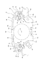
- FIG. 1 is an orthographic view of a first example of a pad assembly according to an embodiment of the present invention as viewed from the back side.
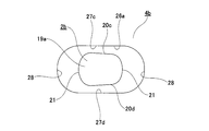
- FIG. 2 is an enlarged view of part A in FIG.
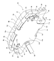
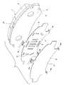
- FIG. 3 is a perspective view of the pad assembly shown in FIG. 1 as viewed from the back side and the outside in the radial direction.
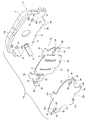
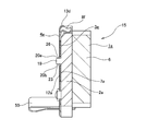
- 4 is an exploded perspective view of the pad assembly shown in FIG. 5 is a cross-sectional view taken along the line BB in FIG.
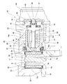
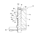
- FIG. 6 is a partial cross-sectional view showing a state in which the pad assembly of the first example is incorporated in a disc brake with an electric parking mechanism.
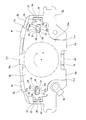
- FIG. 7 is a view similar to FIG. 1 showing a state in which the outer shim plate has rotated counterclockwise during braking of the parking brake.
- FIG. 8 is a view similar to FIG. 1 showing a state in which the outer shim plate rotates clockwise when the parking brake is released.
- FIG. 9 is an enlarged view of a portion corresponding to part A of FIG. 1, showing a second example of the embodiment of the present invention.
- FIG. 10 is a view similar to FIG. 9, showing a third example of the embodiment of the present invention.
- FIG. 11 is a cross-sectional view corresponding to FIG.
- FIG. 12 is a perspective view of the pad assembly as seen from the back side and the outside in the radial direction, showing an example of a conventional structure.
- 13 is an exploded perspective view of the pad assembly shown in FIG. 14 is an orthographic view of the pad assembly shown in FIG. 12 as seen from the back side.
- FIG. 1 to 8 show a first example of an embodiment of the present invention.
- the disc brake pad assembly 15 of this example is used by being incorporated in a disc brake 16 with an electric parking mechanism, and corresponds to a pad (inner pad) 1a and other shim plates described in the claims.
- An inner shim plate 3a and an outer shim plate 4a corresponding to the shim plate recited in the claims are provided.
- the pad 1 a is formed by attaching and fixing a lining 6 to the front surface of the pressure plate 2 a, and is disposed at a portion facing the axial side surface of the rotor 17.
- a locking recess 10a is formed in the circumferential center portion of the outer peripheral edge portion, and a pair of stepped portions 11a, 11a are formed in the circumferential edge portions of the inner peripheral edge portion, An inner diameter side locking recess 18 is formed in the circumferential center of the inner peripheral edge.
- An inner diameter side locking recess 18 is formed in the circumferential center of the inner peripheral edge.
- These engaging projections 19 and 19 are formed in a direction parallel to the rotational direction (tangential direction) of the rotor 17 at the center in the circumferential direction of the pad 1a at a portion radially outward from the pad center position. ing. Further, the both engaging projections 19 and 19 have a cross-sectional shape (end surface shape) of an oval shape having a larger circumferential width dimension L 19 (longer in the circumferential direction) than a radial width dimension H 19. ing. For this reason, the side surfaces (circumferential surfaces) of the both engaging convex portions 19, 19 are a pair of parallel flat surface portions 20a, 20b disposed on both sides in the radial direction, and 1 disposed on both sides in the circumferential direction.
- the pair of convex arcuate surface portions 21 and 21 are continuous. Further, the protruding amount in the axial direction of each of the engaging convex portions 19 is made larger than the thickness dimension in a state where the inner shim plate 3a and the outer shim plate 4a are overlapped. Moreover, the front end surfaces of the both engaging convex portions 19 and 19 are convex curved surfaces whose central portions protrude most along the axial direction.
- the inner shim plate 3a is formed by pressing a stainless steel plate or a metal plate having corrosion resistance and elasticity, such as a stainless steel plate coated with rubber on the surface opposite to the back surface of the pressure plate 2a. It is made by punching and bending.
- Such an inner shim plate 3a is composed of a flat inner body portion 7a and a pair of engagement members bent at a substantially right angle from both ends of the inner body portion 7a in the circumferential direction to the side opposite to the pressure plate 2a. There are provided bent portions 22, 22 and three inner locking pieces 8d, 8e, 8f.
- the engagement protrusions 19 and 19 are respectively inserted into both side portions in the circumferential direction across the portion of the inner body portion 7a that faces (aligns) with the tip surface of the piston 14a.
- through holes 23 and 23 are formed.
- the shape of the through holes 23, 23 is the same shape as the engagement holes 26, 26 described later, and is an oval shape that is long in the circumferential direction.
- As long as 19 can be inserted its shape and size are not particularly limited.
- through holes 9 that are long in the radial direction for holding the grease for lubrication therein, A plurality (9 in the illustrated example) 9 is formed.
- locking through holes 24 and 24 are respectively provided in the center portion in the width direction (radial direction) from the base end portion to the intermediate portion. Is formed.
- guide inclined portions 25 and 25 are formed at portions closer to the distal ends of the both locking bent portions 22 and 22, respectively.
- the inclination directions of both guide inclined portions 25 and 25 are directions in which the distance between the guide inclined portions 25 and 25 increases toward the respective leading edges.
- a total of three portions that is, a central portion in the circumferential direction of the inner peripheral edge and two portions near the both ends in the circumferential direction of the outer peripheral edge, are respectively on the pressure plate 2a side.
- the inner locking pieces 8d, 8e, and 8f that are bent are formed.
- Each of the inner locking pieces 8d, 8e, 8f has its tip half bent to a state where the angle with respect to the inner body portion 7a is an acute angle, and each tip half of each other is in the radial direction. It can be mounted on the back side of the pressure plate 2a while elastically deforming in the direction of widening the interval.
- the inner surface of the front half portion of the inner locking piece 8d is the inner peripheral edge of the pressure plate 2a.
- the inner side locking recesses 18 are elastically contacted, and the inner surfaces of the front half portions of the inner locking pieces 8e and 8f are elastically positioned at two positions near the circumferential ends of the outer peripheral edge of the pressure plate 2a.
- the inner body portion 7a abuts on the back surface of the pressure plate 2a.
- the inner shim plate 3a has a frictional force acting between the pressure plate 2a and the back surface of the pressure plate 2a, and the inner locking pieces 8e and 8f.
- the displacement in the radial direction and the circumferential direction is limited based on engagement (on a non-straight line) with the outer peripheral edge of the pressure plate 2a.
- the outer shim plate 4a is formed by stamping and bending a metal plate having corrosion resistance and elasticity, such as a stainless spring steel plate, by a press work, and has a flat plate-like outer body portion 12a. And three outer locking pieces 13d, 13e, 13f.
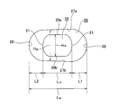
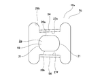
- Engagement holes 26 and 26 are formed. As shown in FIG. 2, these engagement holes 26, 26 have an oval shape in which the circumferential dimension is larger (longer in the circumferential direction) than the radial dimension.
- a pair of straight line portions 27a and 27b arranged in a row and a pair of concave arc portions 28 and 28 arranged on both sides in the circumferential direction are continuous.
- the linear portions 27a and 27b are slightly inclined in the direction of approaching each other along the radial direction as they go toward the center side (the central axis O side of the piston 14a) along the circumferential direction. ing.
- the flat surface portions 20a and 20b and the linear portions 27a are inserted in the engagement holes 26 and 26 having the above-described configuration in a state where the tips of the engagement convex portions 19 and 19 are inserted.
- 27b are opposed to each other in the radial direction, and the convex arc surface portions 21 and 21 and the concave arc portions 28 and 28 are opposed to each other in the circumferential direction.
- the radial width dimension H 26 of each of the engagement holes 26, 26 (the minimum value of the radial width dimensions at the portion facing the engagement convex part 19) of the respective engagement convex parts 19, 19. It is set to be slightly larger than the radial width dimension H 19 (as small as possible within the range in which the engaging projection 19 can be inserted), whereas the circumferential width dimension L 26 of each of the engagement holes 26, 26 is set. However, it is set sufficiently larger than the circumferential width dimension L 19 of each of the engaging projections 19, 19 . As a result, as shown in FIG.
- the inclination angle with respect to the straight line portions 27a and 27b is restricted to a range of 0 degree to 15 degrees (1.5 degrees in the illustrated example).
- locking projecting pieces 29 and 29 are formed in the radially intermediate portion of both circumferential edges in a state of projecting in the circumferential direction from the radially adjacent portions. Yes.
- the distance L 29 between the leading edges of the both locking projections 29, 29 is determined by the distance D 22 between the both locking bent portions 22, 22 formed at both ends in the circumferential direction of the inner shim plate 3a. (L 29 > D 22 ).
- these dimensions L 29 and D 22 are regulated as follows in relation to the guide inclined portions 25 and 25.
- the outer projecting portion 29 is engaged with the retaining hole 24 at one circumferential edge of the outer body portion 12a, and the outer body portion 12a is an inner body portion of the inner shim plate 3a.
- the dimension of each part is regulated so that the tip edge of the locking projection piece 29 on the other end side in the circumferential direction comes into contact with the guide inclined part 25 formed at the tip part of the locking bent part 22.
- a circumferential length L 12 of a portion adjacent to both sides in the radial direction of the both locking projections 29, 29, which is present between the both locking bent portions 22, 22. Is slightly smaller than the distance D 22 (L 12 ⁇ D 22 ).
- each tip half part is in a state where the angle with respect to the outer body portion 12a becomes an acute angle. It is bent and can be mounted on the back side of the pressure plate 2a via the inner shim plate 3a.
- the circumferential width W 10 of the locking recess 10a is, the outer locking piece 13d Is slightly larger than the circumferential width dimension W 13 (W 10 > W 13 ).
- the two step portions 11a, spacing D 11 of 11a to each other, the two outer locking pieces 13e, slightly larger than the distance L 13 between the circumferential outer edge which is opposite edge of 13f (D 11> L 13 ) have been.
- the circumferential displacement of the outer shim plate 4a with respect to the pressure plate 2a is caused by the engagement between the circumferential side edge of the outer locking piece 13d and the locking recess 10a, or the outer locking piece 13e, 13f is regulated by the engaging portion between the circumferential outer edge of 13f and each stepped portion 11a, 11a, and is not restricted by the engagement between each engaging hole 26, 26 and each engaging convex portion 19, 19.
- the dimensions of each part are regulated as follows. That is, as shown in FIG.
- the outer shim plate 4a is in a neutral position with respect to the pressure plate 2a, and the circumferential side edge of the outer locking piece 13d and the locking recess 10a
- the circumferential gap size La (“W 10 ⁇ W 13 ” / 2) between them and the circumferential direction between the outer circumferential edges of the outer locking pieces 13e and 13f and the step portions 11a and 11a
- the circumferential end edges (the tops of the convex arcuate surface portions 21) of the both engaging convex portions 19 and 19 and the both engaging holes 26 and 26 are larger than the gap size Lb ("D 11 -L 13 " / 2).
- the outer shim plate 4a as described above is attached to the pressure plate 2a in a state where the outer main body portion 12a is superimposed on the back surface of the pressure plate 2a via the inner main body portion 7a. In this state, the inner shim plate 3a and the outer shim plate 4a are combined so as to allow a slight relative displacement in the circumferential direction and the radial direction.
- the inner shim plate 3a With both the shim plates 3a and 4a assembled to the pressure plate 2a, the inner shim plate 3a is limited in its circumferential and radial displacement relative to the pressure plate 2a (substantially On the other hand, the outer shim plate 4a is allowed to be slightly displaced from the pressure plate 2 in the circumferential direction, the radial direction, and around the central axis O of the piston 14a.
- the shim plates 3a and 4a may be assembled in advance to the pressure plate 2a, or the inner shim plate 3a and the outer shim plate 4a may be assembled in order to the pressure plate 2a. Also good.
- a wear indicator 55 is attached to the back surface of the pressure plate 2a.
- the wear indicator 55 is formed by bending a long metal plate such as a spring steel plate into a substantially U shape. Thus, it is possible to detect that the lining 6 has been worn to the wear allowable limit thickness due to friction generated during braking.
- the disc brake pad assembly 15 of the present example having the above-described configuration is disposed at a portion facing the inner side surface of the rotor 17 and is incorporated in the disc brake 16 with an electric parking mechanism as shown in FIG. It is.
- the disc brake pad assembly 15 of this example is also arranged at a portion facing the outer side surface of the rotor 17, and cost reduction is achieved by sharing parts.
- a disc brake pad assembly having a conventional structure that does not include the engaging projection 19, the through hole 23, and the engaging hole 26 on the outer side of the rotor 17 may be used.
- the illustrated disc brake 16 with an electric parking mechanism is a floating type disc brake, and the inner side of the support 30 on which a pair of disc brake pad assemblies 15, 15 are supported so as to be capable of axial displacement.
- a caliper 31 having a built-in piston 14a is supported so as to be capable of axial displacement.
- the support 30 is fixed to the vehicle body in a state adjacent to the rotor 17 that rotates together with the wheels.
- the caliper 31 is provided with a caliper claw portion 32 at an outer side end portion and a cylinder portion 33 at an inner side end portion.
- the piston 14a is fitted in an oil-tight manner and capable of axial displacement.
- a conversion mechanism (feed screw mechanism) 34 for changing the rotational movement of the output shaft of the electric motor, which will be described later, to a linear movement is provided inside the cylinder portion 33.
- the conversion mechanism 34 includes a spindle 36 having a male screw portion 35 on the outer peripheral surface, and a nut 38 having a female screw portion 37 on the inner peripheral surface and screwed into the spindle 36.
- the male spline portion 39 formed on the outer peripheral surface of the nut 38 makes relative rotation impossible with respect to the female spline portion 41 formed on the inner peripheral surface of the cylindrical portion 40 constituting the piston 14a, and Engageable for axial displacement.
- a flange portion 42 is provided at an axially intermediate portion of the spindle 36, and between the inner side surface of the flange portion 42 and the inner surface (outer side surface) of the bottom portion 43 constituting the cylinder portion 33, A thrust needle bearing 44 is provided. Further, the inner side end of the spindle 36 is inserted into a communication hole 45 formed so as to penetrate the center of the bottom 43 in the axial direction.
- An electric motor and a speed reducer (not shown) are housed in the casing 46 supported and fixed to the inner side end of the caliper 31. And in the female spline hole 47 opened in the center part of the inner side end part (base end part) of the spindle 36, the front end part of the intermediate shaft 48 that fixes the final gear constituting the speed reducer to the periphery, The spline is engaged.
- a seal groove 49 having a rectangular cross section is formed in the outer peripheral portion of the inner peripheral surface of the cylinder portion 33, and an annular seal member 50 attached to the seal groove 49 is used to connect the outer peripheral surface of the piston 14a.
- a space between the outer peripheral portion of the inner peripheral surface of the cylinder portion 33 is sealed.
- the dust cover 51 closes the gap between the opening of the cylinder 33 and the outer peripheral surface of the tip of the piston 14a.
- a rotation prevention structure using a dowel and a recess is employed between the tip surface of the piston 14a and the inner disc brake pad assembly 15 as in the conventional structure described above. Absent. That is, the front end surface of the piston 14a merely abuts against the back surface of the outer body portion 12a of the outer shim plate 4a constituting the inner disc brake pad assembly 15. In the case of this example, the piston 14a is prevented from rotating by the frictional force acting between the outer shim plate 4a and the frictional force by the annular seal member 50.
- the rotation prevention structure based on mechanical engagement is not employ
- the shapes of the flange portion 42 constituting the spindle 36 and the piston 14a are as follows. It has been devised. Specifically, a convex curved surface portion 52 having a convex arc shape in cross section is formed at a continuous portion between the outer side surface and the outer peripheral surface constituting the flange portion 42, and a cylindrical portion constituting the piston 14a. A straight or curved (concave arc) chamfer 53 is formed on the inner peripheral edge of the 40 inner side end.
- the conversion mechanism 34 which is a combination of the spindle 36 and the nut 38, is incorporated inside the piston 14a whose tip surface is placed on the work table.
- the convex curved surface portion 52 of the flange portion 42 contacts the chamfered portion 53, the center of the conversion mechanism 34 coincides with the center of the piston 14a by utilizing the weight of the conversion mechanism 34.
- a control current is supplied to the electric motor based on the operation of a lever or a switch by the driver, and the output shaft of the electric motor Rotate.
- This rotational motion is transmitted to the spindle 36 through the speed reducer while being decelerated at a predetermined speed reduction ratio.
- the rotational motion transmitted to the spindle 36 is converted into a linear motion that displaces the nut 38 toward the rotor 17 by screwing the male screw portion 35 of the spindle 36 and the female screw portion 37 of the nut 38.
- the Further, the linear movement of the nut 38 displaces the piston 14a toward the rotor 17 (left side in FIG.
- the caliper claw portion 32 of the caliper 31 presses the outer disc brake pad assembly 15 (the lining 6 constituting the pad 1 a) against the outer side surface of the rotor 17.
- the piston 14a is displaced in a direction away from the rotor 17 by rotating the electric motor in the reverse direction, so that the disc brake pad assemblies 15 and 15 are moved to the rotor 17. Get away from.
- the outer shim plate 4a is formed on the outer side even when incorporated in the disc brake 16 with an electric parking mechanism as described above. It is possible to effectively prevent plastic deformation and damage from occurring on the locking pieces 13d, 13e, and 13f. That is, in the case of this example, the engagement protrusions 19 and 19 formed on the pressure plate 2a are inserted into the engagement holes 26 and 26 formed on the outer shim plate 4a, respectively.
- a pair of flat surface portions 20a, 20b constituting the side surfaces of the mating convex portions 19, 19 and a pair of linear portions 27a, 27b constituting the inner peripheral edges of the respective engagement holes 26, 26 are opposed to each other,
- the flat surface portions 20a and 20b and the linear portions 27a and 27b are inclined with respect to each other in a state where the outer shim plate 4a is in a neutral position with respect to the pressure plate 2a. Then, when the parking brake is braked, the counterclockwise rotation around the central axis O of the outer shim plate 4a based on the rotational force acting from the front end surface of the piston 14a, as shown in FIG.
- the linear portion 27b constituting the engaging hole 26 on one end side in the direction (right side in FIG.
- the linear portion 27a constituting the engagement hole 26 on one end side in the direction and the flat surface portion 20a constituting the side surface of the engagement convex portion 19 inserted into the engagement hole 26 are in line contact with each other, and at the other end in the circumferential direction
- the straight portion 27b constituting the side engaging hole 26 and the flat surface portion 20b constituting the side surface of the engaging convex portion 19 inserted into the engaging hole 26 are regulated by line contact.
- the rotational force acting on the outer shim plate 4a from the front end surface of the piston 14a is applied to the outer shim 4a both when the parking brake is applied and when the brake is released.
- the force to be supported even when the outer locking pieces 13d, 13e, 13f formed on the peripheral edge of the plate 4a and the peripheral edge of the pressure plate 2a are not supported or supported. Can be reduced. Therefore, according to the structure of this example, it is possible to effectively prevent the outer locking pieces 13d, 13e, and 13f from undergoing plastic deformation or damage such as breakage.
- the rotational force acting on the outer shim plate 4a from the front end surface of the piston 14a is not supported by the portion that contacts by point contact, but the flat surface portions 20a, 20b Since it is supported by the abutting portion by line contact with the straight portions 27a and 27b, the stress acting on the engaging convex portions 19 and 19 can be suppressed.
- the rotational force is supported by the two contact portions on both sides in the circumferential direction, the stress acting on the engagement convex portions 19 and 19 can be halved. Therefore, the disc brake pad assembly of the present example effectively prevents the occurrence of significant wear and deformation on the side surfaces of the engaging projections 19 and 19 and the inner peripheral edges of the engaging holes 26 and 26. it can.
- FIG. 9 shows a second example of the embodiment of the present invention.
- the inner peripheral edge of the engagement hole 26a formed in the outer shim plate 4b has a pair of linear portions 27c and 27d parallel to each other disposed on both side portions in the radial direction and both side portions in the circumferential direction.
- the pair of concave arc portions 28 and 28 are arranged to be continuous.
- the side surface of the engaging convex portion 19a formed on the back surface of the pressure plate 2b has a pair of flat surface portions 20c and 20d disposed on both sides in the radial direction and a pair of convex arcs disposed on both sides in the circumferential direction. It is comprised by the surface parts 21 and 21 continuing.
- the two flat surface portions 20c and 20d are inclined so as to approach each other along the radial direction toward the opposite side (right side in FIG. 9) of the piston 14a along the circumferential direction.
- the outer shim plate 4b in a neutral position with respect to the pressure plate 2b, there is a diameter between the flat surface portions 20c and 20d and the linear portions 27c and 27d that are opposed in the radial direction.
- a minute gap whose width dimension along the direction gradually changes along the circumferential direction is formed, and between the convex arc surface portions 21 and 21 and the concave arc portions 28 and 28 facing each other in the circumferential direction.
- the inclination angle between the flat surface portions 20c and 20d and the linear portions 27c and 27d opposed to each other in the radial direction through the minute gap is in a range of 0 degrees to 15 degrees (in the illustrated example, 1. 5 degrees).
- the flat surface portions 20c and 20d and the linear portions 27c and 27d can be brought into line contact when the parking brake is braked and released.
- the outer locking pieces 13d, 13e, and 13f (see FIG. 1 and the like) constituting the outer shim plate 4b are plastically deformed or damaged such as breakage. Things can be effectively prevented.
- the outer shim plate 4b is plastically deformed or damaged such as breakage. Things can be effectively prevented.
- FIG. 10 to 11 show a third example of the embodiment of the present invention.
- a substantially H-shaped engagement hole 26b is formed in the outer main body portion 12a constituting the outer shim plate 4c.
- both radial side portions of the central portion in the circumferential direction are opposite to the pressure plate 2a.
- bent portions 54 and 54 are formed in the portions.
- the inner surfaces of the two bent portions 54, 54 facing each other function as the straight portions 27e, 27f.
- the flat surface portions 20a and 20b constituting the side surface of the engaging convex portion 19 and the linear portions 27e and 27f that are the inner surfaces of the bent portions 54 and 54 are provided. It is configured to make line contact. Further, the linear portions 27e and 27f are inclined in a direction approaching each other along the radial direction as they go inward (left side in FIG. 10) along the circumferential direction.
- a lining (6) is attached and fixed to the front surface of the pressure plate (2a).
- the pad (1a) is disposed at a portion facing the axial side surface of the rotor (17), and the back surface thereof is a piston (14a).
- Shim plates inner shim plate 3a, outer shim plate 4a) pressed by the tip surface of
- the shim plate (outer shim plate 4a) includes a flat plate-like main body portion (outer main body portion 12a) and a locking piece bent from the peripheral edge of the main body portion (outer main body portion 12a) toward the pressure plate (2a).
- Outer locking pieces 13d, 13e, 13f), and the front surface of the main body portion (outer main body portion 12a) is directly or other shim plate (inner shim plate 3a) on the back surface of the pressure plate (2a).
- An engagement convex portion (19) projecting in the axial direction of the rotor (17) is provided on a portion of the back surface of the pressure plate (2a) that is disengaged from a portion facing the tip surface of the piston (14a).
- the engagement convex portion (19) is disengaged from the portion of the main body portion (outer main body portion 12a) of the shim plate (outer shim plate 4a) that contacts the tip surface of the piston (14a).
- the linear part which comprises the inner periphery of the said engaging hole (26) (27a, 27b) and the shim plate (outer shim plate 4a) are in a neutral position with respect to the pressure plate (2a), and these flat surface portions (20a, 20b) and linear portions (27a) , 27b) and each other It is inserted in the state, Of the displacement of the shim plate (outer shim plate 4a) with respect to the pressure plate (2a), the movement of the rotor (17) in the circumferential direction is caused by the locking piece (outer body portion 12a) and the pressure plate (2a).
- a bent portion is formed in a state of being bent from the inner peripheral edge portion of the engagement hole (26) to the side opposite to the pressure plate (2a), and the inner side surface of the bent portion is the straight portion ( 27a, 27b), the disc brake pad assembly (15) according to any one of the above [1] to [2].
- the engagement convex portion (19) is provided on both sides of the pressure plate (2a) on both sides in the circumferential direction with a portion facing the tip surface of the piston (14a) on the back surface of the pressure plate (2a).
- the engagement hole (26) is formed on both side portions of the shim plate (outer shim plate 4a) on both sides in the circumferential direction across the portion of the main body portion (outer main body portion 12a) that contacts the front end surface of the piston (14a).
- a disc brake pad assembly (15) according to any one of the above [1] to [3]. [5] A pair of flat surface portions (20a, 20b) is provided on the side surface of the engaging convex portion (19), and a pair of linear portions (27a) is provided on the inner peripheral edge portion of the engaging hole (26).
- the disc brake pad assembly (15) according to any one of [1] to [4], which is regulated by the above. [6] The above [1], wherein the locking pieces (outer locking pieces 13d, 13e, and 13f) are provided at least one each on the outer peripheral edge and the inner peripheral edge of the main body portion (12a). A disc brake pad assembly (15) according to any one of [5] to [5].
- the disc brake pad assembly of the present invention is not limited to the above-described embodiment, and can be appropriately modified and improved.
- the material, shape, dimensions, number, arrangement location, and the like of each component in the above-described embodiment are arbitrary and are not limited as long as the present invention can be achieved.
- This application is based on a Japanese patent application (Japanese Patent Application No. 2014-118648) filed on June 9, 2014, the contents of which are incorporated herein by reference.
- the number of shim plates constituting the disc brake pad assembly of the present invention is not limited to two. It can be performed with only one sheet (excluding the inner shim plate from the structure of the embodiment), and conversely, a third shim plate (for example, an intermediate shim plate) is located between the pressure plate and the inner shim plate.
- the present invention can be implemented with respect to a structure sandwiched between the inner shim plate and the outer shim plate.
- the disc brake pad assembly of the present invention is not limited to the floating type disc brake with an electric parking mechanism, and can be used by being incorporated in electric disc brakes of various other structures.
- the number of engagement protrusions and engagement holes, the formation position, and the formation direction are not limited to the examples shown in the drawings. They can be combined or changed as appropriate.
Landscapes
- Engineering & Computer Science (AREA)
- General Engineering & Computer Science (AREA)
- Mechanical Engineering (AREA)
- Braking Arrangements (AREA)
Abstract
プレッシャプレート(2a)の背面に形成した係合凸部(19)が、外側シム板(4a)に形成した係合孔(26)に挿入される。そして、係合凸部(19)の側面を構成する平坦面部(20a、20b)が、係合孔(26)の内周縁部を構成する直線部(27a、27b)と対向する。又、外側シム板(4a)をプレッシャプレート(2a)に対して中立位置に存在させた状態で、平坦面部(20a、20b)と直線部(27a、27b)とを僅かに傾斜させる。これにより、ピストン(14a)の先端面から外側シム板(4a)に作用する回転力に基づく、この外側シム板(4a)のピストン(14a)の中心軸(O)回りの回転が、平坦面部(20a、20b)と直線部(27a、27b)とを線接触させる事により規制される。
Description
この発明は、ディスクブレーキ用パッド組立体の改良に関する。
自動車の制動に使用するディスクブレーキは、車輪と共に回転するロータを挟んで1対のパッドが配置され、制動時にはこれら両パッドがこのロータの軸方向両側面に押し付けられる様に構成されている。この様なディスクブレーキの基本的構造としては、フローティング型と対向ピストン型との2種類がある。このうちのフローティング型のディスクブレーキは、1対のパッドが軸方向の変位を可能に支持されたサポートに、インナ側にピストンを内蔵したキャリパが、軸方向の変位を可能に支持されている。制動時には、このピストンによりインナ側のパッドがロータのインナ側面に押し付けられ、その反作用として前記キャリパがインナ側に変位する。そして、このキャリパのアウタ側端部に設けたキャリパ爪部により、アウタ側のパッドが前記ロータのアウタ側面に押し付けられる。又、対向ピストン型のディスクブレーキは、1対のパッドが軸方向の変位可能に支持されたキャリパに複数のピストンが、ロータの軸方向両側に配置された状態で設けられている。制動時には、これら各ピストンにより前記両パッドが、前記ロータの軸方向両側面に押し付けられる。何れの場合でも、これら両パッドは、十分な剛性を有するプレッシャプレートの前面にライニングが添着されて成る。そして、制動時に、前記ピストン又は前記キャリパ爪部により、このうちのプレッシャプレートの背面が押圧され、前記ライニングの前面と前記ロータの軸方向両側面とが摩擦する。
尚、本明細書及び請求の範囲で、「軸方向」、「周方向」、「径方向」とは、特に断らない限り、ディスクブレーキ用パッド組立体がディスクブレーキに組み付けられた状態での、ロータの軸方向、周方向、径方向をそれぞれ言う。又、「周縁部」とは、ロータの径方向に関する内周縁部又は外周縁部を言う。
尚、本明細書及び請求の範囲で、「軸方向」、「周方向」、「径方向」とは、特に断らない限り、ディスクブレーキ用パッド組立体がディスクブレーキに組み付けられた状態での、ロータの軸方向、周方向、径方向をそれぞれ言う。又、「周縁部」とは、ロータの径方向に関する内周縁部又は外周縁部を言う。
何れの構造のディスクブレーキの場合であっても、制動時には1対のパッドによりロータが軸方向両側から強く挟持され、これら両パッドを構成するライニングとこのロータの軸方向両側面との当接部に作用する摩擦力により制動が行われる。この様な制動時に、この摩擦力が作用する部分と、前記ピストン又は前記キャリパ爪部が前記両パッドを押圧する部分とは、軸方向に沿ってこれら両パッドの厚さ分だけずれ、このずれに基づいてこれら両パッドの姿勢が不安定になり易い。制動時にこれら両パッドの姿勢が不安定になると、これら両パッドの挙動がスムーズになりづらく、これら両パッドが振動して、鳴きと呼ばれる騒音を発生したり、前記ライニングの偏摩耗の程度が著しくなり易い。
この様な鳴きや偏摩耗を緩和する為に従来から、パッドを構成するプレッシャプレートの背面と、この背面を押圧する為の押圧面であるピストンの先端面又はキャリパ爪部の内側面との間に、シム板を挟持する事が広く行われている。この様なシム板は、1枚のみの単板構成の場合もあるが、鳴きや偏摩耗の抑制効果を向上させる為に、内側シム板と外側シム板とを重ね合わせた2枚構造とする事も広く行われている。又、1枚構造であるか2枚構造であるかを問わず、シム板の内外両周縁部の複数個所に形成した係止片が、前記プレッシャプレートの内外両周縁部に係合する事により、前記シム板をこのプレッシャプレートの背面側に支持する事が行われている。
特許文献1には、ディスクブレーキ用パッド組立体として、図12~14に示す様な構造が記載されている。この従来構造は、パッド1を構成するプレッシャプレート2の背面に、内側シム板3と外側シム板4とから成る組み合わせシム板5が装着されて成る。前記パッド1は、前記プレッシャプレート2の前面(ディスクブレーキへの組み付け時にロータの側面と対向する面)にライニング6が、制動時に加わるブレーキトルクによりずれ動かない様に、大きな結合力により添着固定されて成る。前記内側シム板3は、ステンレス鋼板等の金属板製であり、平板状の内側本体部分7と、複数の内側係止片8a、8b、8cとを備える。又、この内側本体部分7には、それぞれの内側にグリースを保持する為の、複数の透孔9、9が形成されている。又、前記プレッシャプレート2の内外両周縁部のうち、外周縁部の周方向中央部に係止凹部10が形成され、内周縁部の周方向両端寄り部分に1対の段差部11、11が形成されている。前記内側シム板3は、前記各内側係止片8a、8b、8cのうち、外径側の内側係止片8aが前記係止凹部10に係合し、内径側の内側係止片8b、8cが前記両段差部11、11に係合しつつ、これら各内側係止片8a、8b、8cにより前記プレッシャプレート2が、径方向両側から挟持されている。この状態で、前記内側シム板3は、このプレッシャプレート2の背面側に、周方向及び径方向の変位を制限(実質的に阻止)された状態で装着される。
又、前記外側シム板4は、ステンレス鋼板等の金属板製であり、平板状の外側本体部分12と、複数の外側係止片13a、13b、13cとを備える。この様な外側シム板4は、これら各外側係止片13a、13b、13cを前記各内側係止片8a、8b、8cに重ね合わせつつ、前記外側本体部分12を前記内側本体部分7に重ね合わせる。この状態で、前記外側シム板4が前記内側シム板3に、周方向の変位を可能に組み付けられる。この為に、前記外側係止片13aの周方向幅寸法が、前記係止凹部10及び前記内側係止片8aの周方向幅寸法よりも小さくされ、前記両外側係止片13b、13cの互いに反対側側縁である周方向外側縁同士の間隔が、前記両段差部11、11同士の間隔よりも小さくされている。
ところで、上述の様な構成を有するディスクブレーキ用パッド組立体が、電動式パーキング機構付ディスクブレーキなどの電動式ディスクブレーキに組み込んで使用される事も、従来から考えられている。この様な電動式ディスクブレーキでは、電動モータの回転運動を直線運動に変換する為の送りねじ機構等の変換機構により、シリンダ内に嵌装されたピストンが、インナ側に配置されたパッドに向けて押し出される構造が広く採用されている。又、ピストンの回り止めを図り、変換機構によりこのピストンに伝達される回転力を支承する為、このピストンの先端面に凹部が形成され、インナ側に配置されたパッドのプレッシャプレートの背面に形成されたダボを係合させる事が行われている。そこで、上述の様な構成を有するディスクブレーキ用パッド組立体が、電動式ディスクブレーキに組み込んで使用される場合には、プレッシャプレートの背面を覆ったシム板の一部に切り欠きを形成する事で、このプレッシャプレートの背面に形成したダボを、ピストンの先端面に形成した凹部に係合させる事が行われている。
ところが、上述の様なダボと凹部との回転防止構造が採用された場合には、電動モータの制御が複雑になる場合があるなどの理由から、本発明者等によって、これらダボ及び凹部を省略し、ピストンに作用する摩擦力等を利用して、回り止めを行う構造の研究が進められている。そして、この場合には、ディスクブレーキ用パッド組立体が使用される場合にも、ダボと凹部による回転防止構造は設けずに、ピストンの先端面が、ディスクブレーキ用パッド組立体を構成するシム板の裏面に当接する構造を採用する事が考える。但し、単にこの様な構造を採用した場合には、次に述べる様な問題を生じる可能性がある。
即ち、図14に示した様に、制動時、ピストン14の先端面が押圧される外側シム板4の裏面には、このピストン14の先端面を通じて回転力が伝達される。そして、従来構造のディスクブレーキ用パッド組立体の場合には、この様な回転力が、前記外側シム板4の周縁部に設けられた外側係止片13a、13b、13cと、プレッシャプレート2の周縁部(係止凹部10及び段差部11、11)との何れかの係合部によって支承される。そして、前記外側シム板4が、前記プレッシャプレート2に対し、前記ピストン14の中心軸O回りに回転する事が規制される。この為、前記各外側係止片13a、13b、13cに過大な応力が作用する事になり、これら各外側係止片13a、13b、13cに、塑性変形が生じたり、長期間に亙る使用により折損等の損傷を生じる可能性がある。
本発明は、上述の様な事情に鑑みて、電動式ディスクブレーキに組み込んで使用する場合にも、係止片の変形及び損傷を有効に防止できる、ディスクブレーキ用パッド組立体の構造を実現することを目的とする。
本発明の上記目的は、下記構成により達成される。
(1) プレッシャプレートの前面にライニングが添着固定されて成り、ロータの軸方向側面に対向する部分に配置されるパッドと、その背面をピストンの先端面により押圧されるシム板とを備え、
前記シム板は、平板状の本体部分と、前記本体部分の周縁部から前記プレッシャプレート側に折れ曲がった係止片とを有し、前記本体部分の前面が前記プレッシャプレートの背面に直接又は他のシム板を介して重ね合わされた状態で、前記係止片が前記プレッシャプレートの周縁部に係合している、ディスクブレーキ用パッド組立体であって、
前記プレッシャプレートの背面のうち、前記ピストンの先端面と対向(軸方向に重畳)する部分から外れた部分には、前記ロータの軸方向に突出する係合凸部が設けられており、前記係合凸部が、前記シム板の本体部分のうち、前記ピストンの先端面と当接する部分から外れた部分に形成された係合孔内に、前記係合凸部の側面を構成する平坦面部と前記係合孔の内周縁を構成する直線部とが対向すると共に、前記シム板が前記プレッシャプレートに対して中立位置に存在する状態でこれら平坦面部と直線部とが互いに傾斜した状態で挿入されており(尚、前記プレッシャプレートと前記シム板との間に、前記他のシム板が挟持される場合には、この他のシム板に形成された通孔又は切り欠きを挿通した前記係合凸部の先端部が、前記シム板に形成した係合孔に挿入される。)、
前記シム板の前記プレッシャプレートに対する変位のうち、前記ロータの周方向への移動が、前記係止片と前記プレッシャプレートの周縁部との係合部により規制され、
前記ピストンの中心軸回りの回転のうち、少なくとも制動時にこのピストンに作用する方向の回転は、前記平坦面部と前記直線部とが線接触する事により規制される、ディスクブレーキ用パッド組立体。
(2) 前記シム板が前記プレッシャプレートに対して中立位置に存在する状態での前記平坦面部と前記直線部との傾斜角度が、0度(好ましくは0.5度)以上15度以下である、上記(1)に記載したディスクブレーキ用パッド組立体。
(3) 前記係合孔の内周縁部から前記プレッシャプレートとは反対側に折れ曲がる状態で、折り曲げ部が形成されており、前記折り曲げ部の内側面が、前記直線部とされている、上記(1)~(2)の何れか1つに記載したディスクブレーキ用パッド組立体。
(4) 前記係合凸部が、前記プレッシャプレートの背面のうち、前記ピストンの先端面と対向(軸方向に重畳)する部分を挟んで周方向両側部分に設けられていると共に、前記係合孔が、前記シム板の本体部分のうち、前記ピストンの先端面と当接する部分を挟んで周方向両側部分に設けられている、上記(1)~(3)の何れか1つに記載したディスクブレーキ用パッド組立体。
(5) 前記係合凸部の側面に1対の平坦面部を設けられていると共に、前記係合孔の内周縁部に1対の直線部が設けられており、前記ピストンの中心軸回りの両方向の回転は、前記平坦面部と前記直線部とが線接触する事により規制される、上記(1)~(4)の何れか1つに記載したディスクブレーキ用パッド組立体。
(6) 前記係止片が、前記本体部分の外周縁部及び内周縁部に、少なくともそれぞれ1つずつ設けられている、上記(1)~(5)の何れか1つに記載したディスクブレーキ用パッド組立体。
上述の様に構成する本発明のディスクブレーキ用パッド組立体によれば、電動式ディスクブレーキに組み込んで使用する場合にも、係止片の変形及び損傷を有効に防止できる。
即ち、本発明の場合には、プレッシャプレートの背面に形成した係合凸部が、シム板の本体部分に形成した係合孔内に挿入された状態で、この係合凸部の側面を構成する平坦面部と、この係合孔の内周縁を構成する直線部とが対向すると共に、前記シム板が前記プレッシャプレートに対して中立位置に存在する状態でこれら平坦面部と直線部とが互いに傾斜している。そして、制動時に、電動式ディスクブレーキを構成するピストンの先端面から前記シム板に作用する回転力に基づく、このシム板の前記ピストンの中心軸回りの回転は、前記平坦面部と前記直線部とが線接触する事により規制される。この為、本発明の場合には、前記ピストンの先端面から前記シム板に作用する回転力が、このシム板の周縁部に形成した係止片と、前記プレッシャプレートの周縁部との係合部によっては支承されずに済むか、支承される力が小さくて済む。従って、本発明によれば、前記係止片に、塑性変形が生じたり、折損等の損傷が生じる事を有効に防止できる。
更に、本発明の場合には、前記ピストンの先端面から前記シム板に作用する回転力が、点接触で当接する部分で支承されるのではなく、前記平坦面部と前記直線部との線接触による当接部で支承される為、前記係合凸部に作用する応力を抑えられる。この為、前記係合凸部の側面及び前記係合孔の内周縁に、著しい摩耗や変形が生じる事を有効に防止できる。
又、上記(3)に記載した発明によれば、前記平坦面部と前記直線部との接触面積を大きく確保でき、これら両部分に作用する接触面圧を低く抑えられる。この為、前記係合凸部の側面及び前記係合孔の内周縁に、著しい摩耗や変形が生じる事をより一層有効に防止できる。
又、上記(5)に記載した発明によれば、制動解除時に、電動式ディスクブレーキを構成するピストンの先端面から前記シム板に作用する回転力に基づく、このシム板の前記ピストンの中心軸回りの回転を、前記平坦面部と前記直線部とを線接触させる事により規制する事ができる。この為、制動解除時に前記シム板に作用する力によって、前記係止片に変形や損傷が生じる事も防止できる。
又、上記(5)に記載した発明によれば、制動解除時に、電動式ディスクブレーキを構成するピストンの先端面から前記シム板に作用する回転力に基づく、このシム板の前記ピストンの中心軸回りの回転を、前記平坦面部と前記直線部とを線接触させる事により規制する事ができる。この為、制動解除時に前記シム板に作用する力によって、前記係止片に変形や損傷が生じる事も防止できる。
[実施の形態の第1例]
図1~8は、本発明の実施の形態の第1例を示している。本例のディスクブレーキ用パッド組立体15は、電動式パーキング機構付ディスクブレーキ16に組み込んで使用されるもので、パッド(インナパッド)1aと、請求の範囲に記載した他のシム板に相当する内側シム板3aと、請求の範囲に記載したシム板に相当する外側シム板4aとを備える。このうちのパッド1aは、プレッシャプレート2aの前面にライニング6が添着固定されて成り、ロータ17の軸方向側面に対向する部分に配置される。
図1~8は、本発明の実施の形態の第1例を示している。本例のディスクブレーキ用パッド組立体15は、電動式パーキング機構付ディスクブレーキ16に組み込んで使用されるもので、パッド(インナパッド)1aと、請求の範囲に記載した他のシム板に相当する内側シム板3aと、請求の範囲に記載したシム板に相当する外側シム板4aとを備える。このうちのパッド1aは、プレッシャプレート2aの前面にライニング6が添着固定されて成り、ロータ17の軸方向側面に対向する部分に配置される。
前記プレッシャプレート2aには、外周縁部の周方向中央部に係止凹部10aが形成されており、内周縁部の周方向両端寄り部分に1対の段差部11a、11aが形成されており、内周縁部の周方向中央部に内径側係止凹部18が形成されている。又、本例の場合には、前記プレッシャプレート2aの背面のうち、前記ピストン14aの先端面と対向(軸方向に重畳)する部分(図1の斜格子部分)を挟んで周方向両側部分に、前記ロータ17の軸方向に突出する係合凸部(ダボ)19、19がそれぞれ1個ずつ設けられている。これら両係合凸部19、19は、パッド中心位置よりも径方向外寄り部分に、前記パッド1aの周方向中央部での前記ロータ17の回転方向(接線方向)と平行な方向に形成されている。又、前記両係合凸部19、19は、それぞれの断面形状(端面形状)が、径方向幅寸法H19に比べて周方向幅寸法L19が大きい(周方向に長い)小判形状とされている。この為、前記両係合凸部19、19の側面(周面)は、径方向両側部分に配置された互いに平行な1対の平坦面部20a、20bと、周方向両側部分に配置された1対の凸円弧面部21、21とが連続する事により構成されている。又、前記各係合凸部19、19の軸方向に関する突出量は、前記内側シム板3a及び前記外側シム板4aが重ね合わせられた状態での厚さ寸法よりも大きくされている。又、前記両係合凸部19、19の先端面は、中央部が軸方向に沿って最も突出した凸曲面とされている。
又、前記内側シム板3aは、ステンレスのばね鋼板や、前記プレッシャプレート2aの背面と対向する側の面にゴムをコーティングしたステンレスのばね鋼板等、耐食性及び弾性を有する金属板に、プレス加工による打ち抜き加工及び曲げ加工を施す事により造られている。この様な内側シム板3aは、平板状の内側本体部分7aと、この内側本体部分7aの周方向両端部から前記プレッシャプレート2aと反対側に、ほぼ直角に曲げ起こされた、1対の係止折り曲げ部22、22と、3個の内側係止片8d、8e、8fとを備える。
本例の場合には、前記内側本体部分7aのうち、前記ピストン14aの先端面と対向(整合)する部分を挟んで周方向両側部分に、それぞれ前記各係合凸部19、19を挿通させる為の、通孔23、23が形成されている。図示の例では、これら通孔23、23の形状が、後述する係合孔26、26と同一形状とされて、周方向に長い長円形状とされているが、前記係合凸部19、19を挿通可能であれば、その形状及び大きさは特に問わない。又、前記内側本体部分7aのうち、周方向に沿った前記両通孔23、23の間部分には、それぞれの内部に潤滑用のグリースを保持する為の、径方向に長い透孔9、9が複数個(図示の例では2個)形成されている。
又、前記内側シム板3aを構成する係止折り曲げ部22、22のうち、基端部から中間部分に掛けての幅方向(径方向)中央部分には、それぞれ係止透孔24、24が形成されている。又、前記両係止折り曲げ部22、22の先端寄り部分には、それぞれガイド傾斜部25、25が形成されている。これら両ガイド傾斜部25、25の傾斜方向は、それぞれの先端縁に向かうに従って互いの間隔が拡がる方向とされている。
更に、前記内側本体部分7aの内外両周縁のうち、内周縁の周方向中央部分と、外周縁の周方向両端寄り2個所部分との、合計3個所部分には、それぞれ前記プレッシャプレート2a側に折れ曲がった、前記各内側係止片8d、8e、8fが形成されている。これら各内側係止片8d、8e、8fは、それぞれの先半部が、前記内側本体部分7aに対する角度が鋭角となる状態まで折り曲げられており、それぞれの先半部が、径方向に関する互いの間隔を拡げる方向に弾性変形しつつ、前記プレッシャプレート2aの背面側に装着可能とされている。
上述の様な構成を有する前記内側シム板3aが、前記プレッシャプレート2aに対し装着される際には、前記内側係止片8dの先半部内面が、このプレッシャプレート2aの内周縁部の前記内径側係止凹部18に弾性的に当接し、前記両内側係止片8e、8fの先半部内面が、このプレッシャプレート2aの外周縁部の周方向両端寄り部分2個所位置に弾性的に当接した状態で、前記内側本体部分7aが前記プレッシャプレート2aの背面に当接する。そして、この様な装着状態で、前記内側シム板3aは、このプレッシャプレート2aに対し、このプレッシャプレート2aの背面との間に作用する摩擦力、及び、前記両内側係止片8e、8fと前記プレッシャプレート2aの外周縁部との(非直線上の)係合等に基づき、径方向及び周方向に関する変位が制限される。
これに対し、前記外側シム板4aは、ステンレスのばね鋼板等、耐食性及び弾性を有する金属板に、プレス加工による打ち抜き加工及び曲げ加工を施す事により造られており、平板状の外側本体部分12aと、3個の外側係止片13d、13e、13fとを備える。
本例の場合には、前記外側本体部分12aのうち、前記ピストン14aの先端面と当接する部分を挟んで周方向両側部分に、それぞれ前記各係合凸部19、19を挿入する為の、係合孔26、26が形成されている。図2に示すように、これら両係合孔26、26は、径方向寸法に比べて周方向寸法が大きい(周方向に長い)長円形状であり、それぞれの内周縁は、径方向両側部分に配置された1対の直線部27a、27bと、周方向両側部分に配置された1対の凹円弧部28、28とが連続する事により構成されている。又、本例の場合、前記両直線部27a、27b同士が、周方向に沿って中央側(ピストン14aの中心軸O側)に向かう程、径方向に沿って互いに近づく方向に僅かに傾斜している。そして、この様な構成を有する前記各係合孔26、26に、前記係合凸部19、19の先端部がそれぞれ挿入された状態で、前記各平坦面部20a、20bと前記各直線部27a、27bとが径方向に対向すると共に、前記各凸円弧面部21、21と前記各凹円弧部28、28とが周方向に対向している。
又、前記各係合孔26、26の径方向幅寸法H26(係合凸部19と対向する部分での径方向幅寸法のうち最小値)が、前記各係合凸部19、19の径方向幅寸法H19よりも僅かに大きく(係合凸部19を挿通できる範囲で可能な限り小さく)設定されているのに対し、前記各係合孔26、26の周方向幅寸法L26が、前記各係合凸部19、19の周方向幅寸法L19よりも十分に大きく設定されている。これにより、図1に示す様に、前記外側シム板4aが前記プレッシャプレート2aに対して中立位置に存在した状態で、径方向に対向する前記各平坦面部20a、20bと前記各直線部27a、27bとの間には、径方向に沿った幅寸法が周方向に沿って漸次変化する微小隙間がそれぞれ形成されると共に、周方向に対向する前記各凸円弧面部21、21と前記各凹円弧部28、28との間には、周方向に沿った幅寸法が比較的大きな周方向隙間(L1、L2)がそれぞれ形成されている。又、本例の場合、前記外側シム板4aが前記プレッシャプレート2aに対して中立位置に存在した状態で、前記微小隙間を介して径方向に対向する、前記各平坦面部20a、20bと前記各直線部27a、27bとの傾斜角度は、0度以上15度以下の範囲(図示の例では1.5度)に規制されている。
又、前記外側本体部分12aのうち、周方向両端縁の径方向中間部には、それぞれ係止突片29、29が、径方向に隣接する部分よりも周方向に突出する状態で形成されている。そして、これら両係止突片29、29の先端縁同士の距離L29が、前記内側シム板3aの周方向両端部に形成された前記両係止折り曲げ部22、22同士の間隔D22よりも大きくされている(L29>D22)。但し、これら各寸法L29、D22は、前記各ガイド傾斜部25、25との関係で、次の様に規制さている。即ち、前記外側本体部分12aのうちの周方向一端縁で、前記係止突片29が前記係止透孔24に係合しつつ、前記外側本体部分12aが前記内側シム板3aの内側本体部分7aに近づいた状態で、周方向他端側の係止突片29の先端縁が、前記係止折り曲げ部22の先端部に形成したガイド傾斜部25に当接する様に、各部の寸法が規制されている。又、前記外側本体部分12aのうち、前記両係止折り曲げ部22、22同士の間に存在する、前記両係止突片29、29の径方向両側に隣接する部分の周方向長さL12は、前記間隔D22よりも少しだけ小さく(L12<D22)されている。
更に、前記外側本体部分12aの内外両周縁のうち、外周縁の周方向中央部分と、内周縁の周方向両端寄り2個所部分との、合計3個所部分には、それぞれ前記プレッシャプレート2a側に折れ曲がった、前記各外側係止片13d、13e、13fが形成されている。この様な外側係止片13d、13e、13fに関しても、上述した内側係止片8d、8e、8fと同様に、それぞれの先半部が、前記外側本体部分12aに対する角度が鋭角となる状態まで折り曲げられており、前記プレッシャプレート2aの背面側に、前記内側シム板3aを介して装着可能とされている。
本例の場合、前記プレッシャプレート2aに対する前記外側シム板4aの、周方向に関する若干の変位を可能にする為に、前記係止凹部10aの周方向幅寸法W10が、前記外側係止片13dの周方向幅寸法W13よりも少し大きく(W10>W13)されている。又、前記両段差部11a、11a同士の間隔D11が、前記両外側係止片13e、13fの反対側端縁である周方向外側縁同士の距離L13よりも少し大きく(D11>L13)されている。
又、前記プレッシャプレート2aに対する前記外側シム板4aの周方向変位は、前記外側係止片13dの周方向側縁と前記係止凹部10aとの係合部、又は、前記外側係止片13e、13fの周方向外側縁と前記各段差部11a、11aとの係合部によって規制され、前記各係合孔26、26と前記各係合凸部19、19との係合によっては規制されない為に、各部の寸法が、以下の様に規制されている。即ち、図1に示した様に、前記外側シム板4aは、前記プレッシャプレート2aに対し中立位置に存在した状態で、前記外側係止片13dの周方向側縁と前記係止凹部10aとの間の周方向隙間の大きさLa(「W10-W13」/2)、及び、前記外側係止片13e、13fの周方向外側縁と前記各段差部11a、11aとの間の周方向隙間の大きさLb(「D11-L13」/2)よりも、前記両係合凸部19、19の周方向端縁(凸円弧面部21の頂部)と前記両係合孔26、26の周方向端縁(凹円弧部28の底部)との間の周方向隙間L1、L2が、それぞれ大きくされている(L1、L2>La、Lb)。これにより、本例の場合には、前記外側シム板4aが前記プレッシャプレート2aに対して周方向に変位した場合にも、前記各係合凸部19、19と前記各係合孔26、26とが当接しない様にされている。
上述の様な外側シム板4aは、その外側本体部分12aを前記プレッシャプレート2aの背面に、前記内側本体部分7aを介して重ね合わせた状態で、このプレッシャプレート2aに対して装着される。そして、この状態で、前記内側シム板3aと前記外側シム板4aとが、周方向及び径方向に関する若干の相対変位を可能に組み合わされる。
前記両シム板3a、4aが、前記プレッシャプレート2aに対し組み付けられた状態で、このうちの内側シム板3aは、このプレッシャプレート2aに対して、周方向及び径方向の変位が制限(実質的に阻止)されるのに対し、前記外側シム板4aは、前記プレッシャプレート2に対して、周方向、径方向、及び前記ピストン14aの中心軸O回りの若干の変位が許容される。
尚、前記両シム板3a、4aは、予め組み合わせてから前記プレッシャプレート2aに対し組み付けても良いし、このプレッシャプレート2aに対し、内側シム板3aと外側シム板4aとを、順番に組み付けても良い。
尚、前記両シム板3a、4aは、予め組み合わせてから前記プレッシャプレート2aに対し組み付けても良いし、このプレッシャプレート2aに対し、内側シム板3aと外側シム板4aとを、順番に組み付けても良い。
又、本例の場合には、前記プレッシャプレート2aの裏面に、ばね鋼板等の長板状の金属薄板が略U字形に曲げ加工されて成る、ウェアインジケータ55が取り付けられている。これにより、制動時に生じる摩擦により前記ライニング6が摩耗許容極限厚さにまで摩耗した事を検知できる様にしている。
上述の様な構成を有する本例のディスクブレーキ用パッド組立体15は、図6に示す様に、前記ロータ17のインナ側面に対向する部分に配置され、電動式パーキング機構付ディスクブレーキ16に組み込まれる。尚、本例の場合には、本例のディスクブレーキ用パッド組立体15が、前記ロータ17のアウタ側面に対向する部分にも配置されており、部品の共通化によるコスト低減が図られているが、このロータ17のアウタ側には、係合凸部19、通孔23、及び、係合孔26をそれぞれ備えない、従来構造のディスクブレーキ用パッド組立体を使用する事もできる。
図示の電動式パーキング機構付ディスクブレーキ16は、フローティング型のディスクブレーキであり、1対のディスクブレーキ用パッド組立体15、15が軸方向の変位を可能に支持されたサポート30に対し、インナ側にピストン14aを内蔵したキャリパ31が、軸方向の変位を可能に支持されている。又、前記サポート30は、車輪と共に回転する前記ロータ17に隣接する状態で、車体に固定されている。
前記キャリパ31は、アウタ側端部にキャリパ爪部32が設けられ、インナ側端部にシリンダ部33が設けられている。そして、このシリンダ部33内には、前記ピストン14aが、油密に、且つ、軸方向の変位を可能に嵌装されている。又、このシリンダ部33の内側には、後述する電動モータの出力軸の回転運動を直線運動に変更する為の変換機構(送りねじ機構)34が設けられている。この変換機構34は、外周面に雄ねじ部35を有するスピンドル36と、内周面に雌ねじ部37を有してこのスピンドル36に螺合したナット38とを備えている。そして、このうちのナット38の外周面に形成した雄スプライン部39が、前記ピストン14aを構成する円筒部40の内周面に形成した雌スプライン部41に対し、相対回転を不能に、且つ、軸方向変位を可能に係合している。又、前記スピンドル36の軸方向中間部にはフランジ部42が設けられており、このフランジ部42のインナ側面と前記シリンダ部33を構成する底部43の内面(アウタ側面)との間には、スラストニードル軸受44が設けられている。又、前記スピンドル36のインナ側端部が、前記底部43の中央部を軸方向に貫通する状態で形成された連通孔45内に挿入されている。
又、前記キャリパ31のインナ側端部に支持固定したケーシング46内には、図示しない電動モータ及び減速機が収納されている。そして、前記スピンドル36のインナ側端部(基端部)の中央部に開口した雌スプライン孔47内には、前記減速機を構成する最終歯車を周囲に固定した中間軸48の先端部が、スプライン係合している。
又、前記シリンダ部33の内周面のうち、アウタ寄り部分に断面矩形状のシール溝49が形成されており、このシール溝49に装着した環状シール部材50により、前記ピストン14aの外周面と前記シリンダ部33の内周面のアウタ寄り部分との間が密封されている。又、前記シリンダ部33の開口部と前記ピストン14aの先端部外周面との間が、ダストカバー51により塞がれている。
特に本例の場合には、前記ピストン14aの先端面と、インナ側のディスクブレーキ用パッド組立体15との間で、前述した従来構造の様な、ダボと凹部による回転防止構造が採用されていない。即ち、前記ピストン14aの先端面は、前記インナ側のディスクブレーキ用パッド組立体15を構成する外側シム板4aの外側本体部分12aの背面に、単に当接しているだけである。本例の場合には、前記外側シム板4aとの間に作用する摩擦力、及び、前記環状シール部材50による摩擦力により、前記ピストン14aの回り止めが図られている。この様に、本例の場合には、前記ピストン14aに対して、機械的係合に基づく回転防止構造が採用されていない。従って、パーキングブレーキの制動時及び制動解除時には、前記ピストン14aが、前記シリンダ部33に対して僅かに相対回転する。尚、本例の場合、サービスブレーキの制動は、このシリンダ部33に圧油を送り込む事により行う為、前記ピストン14aに回転が生じる事はない。
又、本例の場合には、上述した様な電動式パーキング機構付ディスクブレーキ16の組立作業の作業効率を向上する為に、前記スピンドル36を構成するフランジ部42と、前記ピストン14aの形状が工夫されている。具体的には、このフランジ部42を構成するアウタ側面と外周面との連続部に、断面形状が凸円弧形である凸曲面部52が形成されると共に、前記ピストン14aを構成する円筒部40のインナ側端部内周縁部に、直線状又は曲線状(凹円弧状)の面取り部53が形成されている。そして、電動式パーキング機構付ディスクブレーキ16の組立作業時に、先端面が作業台に載置された前記ピストン14aの内側に、前記スピンドル36と前記ナット38とを組み合わせて成る前記変換機構34が組み込まれる際に、前記フランジ部42の凸曲面部52が前記面取り部53に当接する事により、前記変換機構34の自重を利用して、この変換機構34の中心が前記ピストン14aの中心に一致する様にしている。
本例の電動式パーキング機構付ディスクブレーキ16により、パーキングブレーキを作動させるには、運転手によるレバー又はスイッチ等の操作に基づき、前記電動モータに制御電流を供給して、この電動モータの出力軸を回転させる。この回転運動は、前記減速機を介して、所定の減速比で減速された状態で、前記スピンドル36へと伝わる。そして、このスピンドル36に伝わった回転運動は、このスピンドル36の雄ねじ部35と、前記ナット38の雌ねじ部37との螺合により、このナット38を前記ロータ17側へ変位させる直線運動に変換される。更に、このナット38の直線運動が、前記ピストン14aを前記ロータ17側(図6の左側)へと変位させて、インナ側のディスクブレーキ用パッド組立体15(パッド1aを構成するライニング6)を前記ロータ17のインナ側面に押し付ける。すると、この押し付け力の反作用として前記キャリパ31のキャリパ爪部32が、アウタ側のディスクブレーキ用パッド組立体15(パッド1aを構成するライニング6)を、前記ロータ17のアウタ側面に押し付ける。これに対し、パーキングブレーキの解除時には、前記電動モータを逆回転させる事によって前記ピストン14aが、前記ロータ17から離れる方向に変位して、前記両ディスクブレーキ用パッド組立体15、15が前記ロータ17から離される。
以上の様な構成を有する本例のディスクブレーキ用パッド組立体15によれば、上述した様に電動式パーキング機構付ディスクブレーキ16に組み込んで使用する場合にも、外側シム板4aを構成する外側係止片13d、13e、13fに、塑性変形や損傷が生じる事を有効に防止できる。
即ち、本例の場合には、前記プレッシャプレート2aに形成した係合凸部19、19が、前記外側シム板4aに形成した係合孔26、26内に挿入された状態で、これら各係合凸部19、19の側面を構成する1対の平坦面部20a、20bと、前記各係合孔26、26の内周縁を構成する1対の直線部27a、27bとがそれぞれ対向すると共に、前記外側シム板4aが前記プレッシャプレート2aに対して中立位置に存在する状態で前記各平坦面部20a、20bと前記各直線部27a、27bとが互いに傾斜している。そして、パーキングブレーキの制動時に、前記ピストン14aの先端面から作用する回転力に基づく、前記外側シム板4aの前記中心軸O回りの反時計方向の回転が、図7に示した様に、周方向一端側(図7の右側)の係合孔26を構成する直線部27bと、この係合孔26に挿入された前記係合凸部19の側面を構成する平坦面部20bとが線接触すると同時に、周方向他端側(図7の左側)の係合孔26を構成する直線部27aと、この係合孔26に挿入された前記係合凸部19の側面を構成する平坦面部20aとが線接触する事により規制される。又、パーキングブレーキの制動解除時に、前記ピストン14aの先端面から作用する回転力に基づく、前記外側シム板4aの前記中心軸O回りの時計方向の回転が、図8に示した様に、周方向一端側の係合孔26を構成する直線部27aと、この係合孔26に挿入された前記係合凸部19の側面を構成する平坦面部20aとが線接触すると同時に、周方向他端側の係合孔26を構成する直線部27bと、この係合孔26に挿入された前記係合凸部19の側面を構成する平坦面部20bとが線接触する事により規制される。
即ち、本例の場合には、前記プレッシャプレート2aに形成した係合凸部19、19が、前記外側シム板4aに形成した係合孔26、26内に挿入された状態で、これら各係合凸部19、19の側面を構成する1対の平坦面部20a、20bと、前記各係合孔26、26の内周縁を構成する1対の直線部27a、27bとがそれぞれ対向すると共に、前記外側シム板4aが前記プレッシャプレート2aに対して中立位置に存在する状態で前記各平坦面部20a、20bと前記各直線部27a、27bとが互いに傾斜している。そして、パーキングブレーキの制動時に、前記ピストン14aの先端面から作用する回転力に基づく、前記外側シム板4aの前記中心軸O回りの反時計方向の回転が、図7に示した様に、周方向一端側(図7の右側)の係合孔26を構成する直線部27bと、この係合孔26に挿入された前記係合凸部19の側面を構成する平坦面部20bとが線接触すると同時に、周方向他端側(図7の左側)の係合孔26を構成する直線部27aと、この係合孔26に挿入された前記係合凸部19の側面を構成する平坦面部20aとが線接触する事により規制される。又、パーキングブレーキの制動解除時に、前記ピストン14aの先端面から作用する回転力に基づく、前記外側シム板4aの前記中心軸O回りの時計方向の回転が、図8に示した様に、周方向一端側の係合孔26を構成する直線部27aと、この係合孔26に挿入された前記係合凸部19の側面を構成する平坦面部20aとが線接触すると同時に、周方向他端側の係合孔26を構成する直線部27bと、この係合孔26に挿入された前記係合凸部19の側面を構成する平坦面部20bとが線接触する事により規制される。
以上の様に、本例の場合には、パーキングブレーキの制動時及び制動解除時の何れの場合にも、前記ピストン14aの先端面から前記外側シム板4aに作用する回転力が、この外側シム板4aの周縁部に形成した外側係止片13d、13e、13fと、前記プレッシャプレート2aの周縁部との係合部によって支承されずに済むか、支承される場合にも、支承される力を小さくできる。従って、本例の構造によれば、前記各外側係止片13d、13e、13fに、塑性変形が生じたり、折損等の損傷が生じたりする事を有効に防止できる。
更に、本例の場合には、前記ピストン14aの先端面から前記外側シム板4aに作用する回転力が、点接触で当接する部分で支承されるのではなく、前記各平坦面部20a、20bと前記各直線部27a、27bとの線接触による当接部で支承される為、前記各係合凸部19、19に作用する応力を抑えられる。しかも、本例の場合には、前記回転力が、周方向両側の2個所の当接部で支承される為、前記各係合凸部19、19に作用する応力を半減できる。この為、本例のディスクブレーキ用パッド組立体は、前記各係合凸部19、19の側面及び前記各係合孔26、26の内周縁に、著しい摩耗や変形が生じる事を有効に防止できる。
[実施の形態の第2例]
図9は、本発明の実施の形態の第2例を示している。本例の場合には、外側シム板4bに形成される係合孔26aの内周縁は、径方向両側部分に配置された互いに平行な1対の直線部27c、27dと、周方向両側部分に配置された1対の凹円弧部28、28とが連続する事により構成されている。又、プレッシャプレート2bの背面に形成した係合凸部19aの側面は、径方向両側部分に配置された1対の平坦面部20c、20dと、周方向両側部分に配置された1対の凸円弧面部21、21とが連続する事により構成されている。又、前記両平坦面部20c、20d同士が、周方向に沿ってピストン14aの中心軸Oと反対側(図9の右側)に向かう程、径方向に沿って互いに近づく方向に傾斜している。
図9は、本発明の実施の形態の第2例を示している。本例の場合には、外側シム板4bに形成される係合孔26aの内周縁は、径方向両側部分に配置された互いに平行な1対の直線部27c、27dと、周方向両側部分に配置された1対の凹円弧部28、28とが連続する事により構成されている。又、プレッシャプレート2bの背面に形成した係合凸部19aの側面は、径方向両側部分に配置された1対の平坦面部20c、20dと、周方向両側部分に配置された1対の凸円弧面部21、21とが連続する事により構成されている。又、前記両平坦面部20c、20d同士が、周方向に沿ってピストン14aの中心軸Oと反対側(図9の右側)に向かう程、径方向に沿って互いに近づく方向に傾斜している。
又、前記外側シム板4bが前記プレッシャプレート2bに対して中立位置に存在した状態で、径方向に対向する前記各平坦面部20c、20dと前記各直線部27c、27dとの間には、径方向に沿った幅寸法が周方向に沿って漸次変化する微小隙間がそれぞれ形成されると共に、周方向に対向する前記各凸円弧面部21、21と前記各凹円弧部28、28との間には、周方向に沿った幅寸法が比較的大きな隙間がそれぞれ形成されている。又、前記微小隙間を介して径方向に対向する、前記各平坦面部20c、20dと前記各直線部27c、27dとの傾斜角度は、0度以上15度以下の範囲(図示の例では1.5度)に規制されている。
以上の様な構成を有する本例の場合にも、パーキングブレーキの制動時及び制動解除時には、前記各平坦面部20c、20dと前記各直線部27c、27dとを線接触させる事ができる。この為、本例のディスクブレーキ用パッド組立体は、外側シム板4bを構成する外側係止片13d、13e、13f(図1等参照)に、塑性変形が生じたり、折損等の損傷が生じる事を有効に防止できる。
その他の構成及び作用効果に就いては、上述した実施の形態の第1例の場合と同様である。
その他の構成及び作用効果に就いては、上述した実施の形態の第1例の場合と同様である。
[実施の形態の第3例]
図10~11は、本発明の実施の形態の第3例を示している。本例の場合には、外側シム板4cを構成する外側本体部分12aに、略H字形の係合孔26bが形成されている。又、この係合孔26bの内周縁部のうち、周方向中央部(径方向幅寸法が周方向両側部分よりも小さくなった部分)の径方向両側部分が、それぞれプレッシャプレート2aとは反対側(図11の左側)に折り曲げられる事により、当該部分にそれぞれ折り曲げ部54、54が形成されている。そして、本例の場合には、これら両折り曲げ部54、54の互いに対向する内側面が、直線部27e、27fとして機能している。即ち、パーキングブレーキの制動時及び制動解除時には、係合凸部19の側面を構成する平坦面部20a、20bと、前記各折り曲げ部54、54の内側面である前記各直線部27e、27fとが線接触する様に構成されている。又、前記両直線部27e、27f同士は、周方向に沿って内側(図10の左側)に向かう程、径方向に沿って互いに近づく方向に傾斜している。
図10~11は、本発明の実施の形態の第3例を示している。本例の場合には、外側シム板4cを構成する外側本体部分12aに、略H字形の係合孔26bが形成されている。又、この係合孔26bの内周縁部のうち、周方向中央部(径方向幅寸法が周方向両側部分よりも小さくなった部分)の径方向両側部分が、それぞれプレッシャプレート2aとは反対側(図11の左側)に折り曲げられる事により、当該部分にそれぞれ折り曲げ部54、54が形成されている。そして、本例の場合には、これら両折り曲げ部54、54の互いに対向する内側面が、直線部27e、27fとして機能している。即ち、パーキングブレーキの制動時及び制動解除時には、係合凸部19の側面を構成する平坦面部20a、20bと、前記各折り曲げ部54、54の内側面である前記各直線部27e、27fとが線接触する様に構成されている。又、前記両直線部27e、27f同士は、周方向に沿って内側(図10の左側)に向かう程、径方向に沿って互いに近づく方向に傾斜している。
以上の様な構成を有する本例の場合には、前記各平坦面部20a、20bと前記各直線部27e、27fとの接触面積を大きく確保できる為、これら両部分に作用する接触面圧を低く抑えられる。この為、本例のディスクブレーキ用パッド組立体は、前記各係合凸部19の側面及び前記各係合孔26bの内周縁に、著しい摩耗や変形が生じる事をより一層有効に防止できる。
その他の構成及び作用効果に就いては、前述した実施の形態の第1例の場合と同様である。
その他の構成及び作用効果に就いては、前述した実施の形態の第1例の場合と同様である。
ここで、上述した本発明に係るディスクブレーキ用パッド組立体の実施の形態の特徴をそれぞれ以下に簡潔に纏めて列記する。
[1] プレッシャプレート(2a)の前面にライニング(6)が添着固定されて成り、ロータ(17)の軸方向側面に対向する部分に配置されるパッド(1a)と、その背面をピストン(14a)の先端面により押圧されるシム板(内側シム板3a,外側シム板4a)とを備え、
前記シム板(外側シム板4a)は、平板状の本体部分(外側本体部分12a)と、前記本体部分(外側本体部分12a)の周縁部から前記プレッシャプレート(2a)側に折れ曲がった係止片(外側係止片13d,13e,13f)とを有し、前記本体部分(外側本体部分12a)の前面が前記プレッシャプレート(2a)の背面に直接又は他のシム板(内側シム板3a)を介して重ね合わされた状態で、前記係止片(外側係止片13d,13e,13f)が前記プレッシャプレート(2a)の周縁部に係合している、ディスクブレーキ用パッド組立体(15)であって、
前記プレッシャプレート(2a)の背面のうち、前記ピストン(14a)の先端面と対向する部分から外れた部分には、前記ロータ(17)の軸方向に突出する係合凸部(19)が設けられており、前記係合凸部(19)が、前記シム板(外側シム板4a)の本体部分(外側本体部分12a)のうち、前記ピストン(14a)の先端面と当接する部分から外れた部分に形成された係合孔(26)内に、前記係合凸部(19)の側面を構成する平坦面部(20a,20b)と前記係合孔(26)の内周縁を構成する直線部(27a,27b)とが対向すると共に、前記シム板(外側シム板4a)が前記プレッシャプレート(2a)に対して中立位置に存在する状態でこれら平坦面部(20a,20b)と直線部(27a,27b)とが互いに傾斜した状態で挿入されており、
前記シム板(外側シム板4a)の前記プレッシャプレート(2a)に対する変位のうち、前記ロータ(17)の周方向への移動が、前記係止片(外側本体部分12a)と前記プレッシャプレート(2a)の周縁部との係合部により規制され、
前記ピストン(14a)の中心軸(O)回りの回転のうち、少なくとも制動時にこのピストン(14a)に作用する方向の回転は、前記平坦面部(20a,20b)と前記直線部(27a,27b)とが線接触する事により規制される、
ディスクブレーキ用パッド組立体(15)。
[2] 前記シム板(外側シム板4a)が前記プレッシャプレート(2a)に対して中立位置に存在する状態での前記平坦面部(20a,20b)と前記直線部(27a,27b)との傾斜角度が、0度以上15度以下である、上記[1]に記載したディスクブレーキ用パッド組立体(15)。
[3] 前記係合孔(26)の内周縁部から前記プレッシャプレート(2a)とは反対側に折れ曲がる状態で、折り曲げ部が形成されており、前記折り曲げ部の内側面が、前記直線部(27a、27b)とされている、上記[1]~[2]のうちの何れか1つに記載したディスクブレーキ用パッド組立体(15)。
[4] 前記係合凸部(19)が、前記プレッシャプレート(2a)の背面のうち、前記ピストン(14a)の先端面と対向する部分を挟んで周方向両側部分に設けられていると共に、前記係合孔(26)が、前記シム板(外側シム板4a)の本体部分(外側本体部分12a)のうち、前記ピストン(14a)の先端面と当接する部分を挟んで周方向両側部分に設けられている、上記[1]~[3]のうちの何れか1つに記載したディスクブレーキ用パッド組立体(15)。
[5] 前記係合凸部(19)の側面に1対の平坦面部(20a,20b)が設けられていると共に、前記係合孔(26)の内周縁部に1対の直線部(27a,27b)が設けられており、前記ピストン(14a)の中心軸(O)回りの両方向の回転は、前記平坦面部(20a,20b)と前記直線部(27a,27b)とが線接触する事により規制される、上記[1]~[4]のうちの何れか1つに記載したディスクブレーキ用パッド組立体(15)。
[6] 前記係止片(外側係止片13d,13e,13f)が、前記本体部分(12a)の外周縁部及び内周縁部に、少なくともそれぞれ1つずつ設けられている、上記[1]~[5]のうちの何れか1つに記載したディスクブレーキ用パッド組立体(15)。
なお、本発明のディスクブレーキ用パッド組立体は、上述した実施の形態に限定されるものではなく、適宜、変形、改良等が可能である。その他、上述した実施の形態における各構成要素の材質、形状、寸法、数、配置箇所等は本発明を達成できるものであれば任意であり、限定されない。
また、本出願は、2014年6月9日出願の日本特許出願(特願2014-118648)に基づくものであり、その内容はここに参照として取り込まれる。
また、本出願は、2014年6月9日出願の日本特許出願(特願2014-118648)に基づくものであり、その内容はここに参照として取り込まれる。
本発明のディスクブレーキ用パッド組立体を構成するシム板の数は、2枚に限定されるものではない。1枚のみで実施する(実施の形態の構造から内側シム板を除く)事もできるし、逆に、3枚目のシム板(例えば中間シム板)が、プレッシャプレートと内側シム板との間、又は、内側シム板と外側シム板との間に挟持される構造に関して、本発明を実施する事もできる。又、本発明のディスクブレーキ用パッド組立体は、フローティング型の電動式パーキング機構付ディスクブレーキに限定されず、その他の各種構造の電動式ディスクブレーキに組み込んで使用する事ができる。更に、係合凸部及び係合孔の数、形成位置及び形成方向は、何れも図示の例に限定されず、本発明の効果を得られる限り、前記各実施の形態の各例の構造を適宜組み合わせたり、適宜変更する事ができる。
1、1a パッド
2、2a、2b プレッシャプレート
3、3a 内側シム板(シム板)
4、4a、4b 外側シム板(シム板)
5 組み合わせシム板
6 ライニング
7、7a 内側本体部分
8a~8f 内側係止片
9 透孔
10、10a 係止凹部
11、11a 段差部
12、12a 外側本体部分(本体部分)
13a~13f 外側係止片(係止片)
14 ピストン
15 ディスクブレーキ用パッド組立体
16 電動式パーキング機構付ディスクブレーキ
17 ロータ
18 内径側係止凹部
19、19a 係合凸部
20a~20d 平坦面部
21 凸円弧面部
22 係止折り曲げ部
23 通孔
24 係止透孔
25 ガイド傾斜部
26、26a、26b 係合孔
27a~27f 直線部
28 凹円弧部
29 係止突片
30 サポート
31 キャリパ
32 キャリパ爪部
33 シリンダ部
34 変換機構
35 雄ねじ部
36 スピンドル
37 雌ねじ部
38 ナット
39 雄スプライン部
40 円筒部
41 雌スプライン部
42 フランジ部
43 底部
44 スラストニードル軸受
45 連通孔
46 ケーシング
47 雌スプライン孔
48 中間軸
49 シール溝
50 環状シール部材
51 ダストカバー
52 凸曲面部
53 面取り部
54 折り曲げ部
55 ウェアインジケータ
Claims (6)
- プレッシャプレートの前面にライニングが添着固定されて成り、ロータの軸方向側面に対向する部分に配置されるパッドと、その背面をピストンの先端面により押圧されるシム板とを備え、
前記シム板は、平板状の本体部分と、前記本体部分の周縁部から前記プレッシャプレート側に折れ曲がった係止片とを有し、前記本体部分の前面が前記プレッシャプレートの背面に直接又は他のシム板を介して重ね合わされた状態で、前記係止片が前記プレッシャプレートの周縁部に係合している、ディスクブレーキ用パッド組立体であって、
前記プレッシャプレートの背面のうち、前記ピストンの先端面と対向する部分から外れた部分には、前記ロータの軸方向に突出する係合凸部が設けられており、前記係合凸部が、前記シム板の本体部分のうち、前記ピストンの先端面と当接する部分から外れた部分に形成された係合孔内に、前記係合凸部の側面を構成する平坦面部と前記係合孔の内周縁を構成する直線部とが対向すると共に、前記シム板が前記プレッシャプレートに対して中立位置に存在する状態でこれら平坦面部と直線部とが互いに傾斜した状態で挿入されており、
前記シム板の前記プレッシャプレートに対する変位のうち、前記ロータの周方向への移動が、前記係止片と前記プレッシャプレートの周縁部との係合部により規制され、
前記ピストンの中心軸回りの回転のうち、少なくとも制動時にこのピストンに作用する方向の回転は、前記平坦面部と前記直線部とが線接触する事により規制される、
ディスクブレーキ用パッド組立体。 - 前記シム板が前記プレッシャプレートに対して中立位置に存在する状態での前記平坦面部と前記直線部との傾斜角度が、0度以上15度以下である、請求項1に記載したディスクブレーキ用パッド組立体。
- 前記係合孔の内周縁部から前記プレッシャプレートとは反対側に折れ曲がる状態で、折り曲げ部が形成されており、前記折り曲げ部の内側面が、前記直線部とされている、請求項1~2のうちの何れか1項に記載したディスクブレーキ用パッド組立体。
- 前記係合凸部が、前記プレッシャプレートの背面のうち、前記ピストンの先端面と対向する部分を挟んで周方向両側部分に設けられていると共に、前記係合孔が、前記シム板の本体部分のうち、前記ピストンの先端面と当接する部分を挟んで周方向両側部分に設けられている、請求項1~3のうちの何れか1項に記載したディスクブレーキ用パッド組立体。
- 前記係合凸部の側面に1対の平坦面部が設けられていると共に、前記係合孔の内周縁部に1対の直線部が設けられており、前記ピストンの中心軸回りの両方向の回転は、前記平坦面部と前記直線部とが線接触する事により規制される、請求項1~4のうちの何れか1項に記載したディスクブレーキ用パッド組立体。
- 前記係止片が、前記本体部分の外周縁部及び内周縁部に、少なくともそれぞれ1つずつ設けられている、請求項1~5のうちの何れか1項に記載したディスクブレーキ用パッド組立体。
Priority Applications (3)
| Application Number | Priority Date | Filing Date | Title |
|---|---|---|---|
| EP15806897.3A EP3153736B1 (en) | 2014-06-09 | 2015-06-09 | Pad assembly for disk brake |
| US15/315,040 US10041554B2 (en) | 2014-06-09 | 2015-06-09 | Pad assembly for disc brake |
| CN201580031157.3A CN106460976B (zh) | 2014-06-09 | 2015-06-09 | 用于盘式制动器的衬块组件 |
Applications Claiming Priority (2)
| Application Number | Priority Date | Filing Date | Title |
|---|---|---|---|
| JP2014-118648 | 2014-06-09 | ||
| JP2014118648A JP6284831B2 (ja) | 2014-06-09 | 2014-06-09 | ディスクブレーキ用パッド組立体 |
Publications (1)
| Publication Number | Publication Date |
|---|---|
| WO2015190495A1 true WO2015190495A1 (ja) | 2015-12-17 |
Family
ID=54833585
Family Applications (1)
| Application Number | Title | Priority Date | Filing Date |
|---|---|---|---|
| PCT/JP2015/066643 Ceased WO2015190495A1 (ja) | 2014-06-09 | 2015-06-09 | ディスクブレーキ用パッド組立体 |
Country Status (5)
| Country | Link |
|---|---|
| US (1) | US10041554B2 (ja) |
| EP (1) | EP3153736B1 (ja) |
| JP (1) | JP6284831B2 (ja) |
| CN (1) | CN106460976B (ja) |
| WO (1) | WO2015190495A1 (ja) |
Families Citing this family (17)
| Publication number | Priority date | Publication date | Assignee | Title |
|---|---|---|---|---|
| US10352384B2 (en) | 2015-04-24 | 2019-07-16 | Nissin Kogyo Co., Ltd. | Disc brake device for a vehicle |
| JP2017133579A (ja) * | 2016-01-27 | 2017-08-03 | 曙ブレーキ工業株式会社 | ディスクブレーキ装置およびディスクブレーキ装置用ブレーキパッド |
| CN109073010A (zh) * | 2016-04-18 | 2018-12-21 | 日信工业株式会社 | 车辆用盘式制动器 |
| IT201700013292A1 (it) * | 2017-02-07 | 2018-08-07 | Campagnolo Srl | Pastiglia per freno a disco di bicicletta |
| KR101908011B1 (ko) * | 2017-03-23 | 2018-10-16 | 주식회사 만도 | 차량용 디스크브레이크 |
| WO2019133596A1 (en) * | 2017-12-28 | 2019-07-04 | Kelsey-Hayes Company | Uni-directional anti-rotation member for a disc brake assembly with an electric parking brake |
| CN113646555A (zh) * | 2019-04-17 | 2021-11-12 | 日立安斯泰莫株式会社 | 盘式制动器以及层叠垫片 |
| KR102249396B1 (ko) | 2019-11-14 | 2021-05-07 | 현대모비스 주식회사 | 브레이크 장치용 브레이크 패드 |
| KR102899539B1 (ko) * | 2020-01-31 | 2025-12-12 | 에이치엘만도 주식회사 | 커버 심 어셈블리 |
| KR102778997B1 (ko) * | 2020-02-03 | 2025-03-12 | 에이치엘만도 주식회사 | 차량용 브레이크 |
| JP1677174S (ja) * | 2020-04-06 | 2021-01-18 | ||
| JP1677175S (ja) * | 2020-04-06 | 2021-01-18 | ||
| JP7427555B2 (ja) * | 2020-07-22 | 2024-02-05 | 曙ブレーキ工業株式会社 | ディスクブレーキ装置 |
| USD950444S1 (en) * | 2020-09-22 | 2022-05-03 | Hitachi Astemo, Ltd. | Disk brake friction pad for vehicles |
| CN112228476B (zh) * | 2020-12-21 | 2021-02-19 | 山东明宇重工机械有限公司 | 装载机驱动桥钳盘式制动器制动片锁紧结构 |
| DE102022204757A1 (de) * | 2022-05-16 | 2023-11-16 | Hl Mando Corporation | Platte für einen Fahrzeugbremsbelag mit Wärmeabfuhrteilen |
| KR102897490B1 (ko) * | 2023-06-16 | 2025-12-12 | 에이치엘만도 주식회사 | 캘리퍼 브레이크 |
Citations (4)
| Publication number | Priority date | Publication date | Assignee | Title |
|---|---|---|---|---|
| JPH03118328U (ja) * | 1990-03-19 | 1991-12-06 | ||
| JP2005315422A (ja) * | 2004-04-29 | 2005-11-10 | Robert Bosch Gmbh | 振動吸収用の中間板及びこれを備えたディスクブレーキ |
| JP2007315541A (ja) * | 2006-05-29 | 2007-12-06 | Akebono Brake Ind Co Ltd | 対向ピストン型ディスクブレーキ |
| WO2013039174A1 (ja) * | 2011-09-13 | 2013-03-21 | 曙ブレーキ工業株式会社 | ディスクブレーキ用パッド組立体 |
Family Cites Families (14)
| Publication number | Priority date | Publication date | Assignee | Title |
|---|---|---|---|---|
| US4995482A (en) * | 1988-06-14 | 1991-02-26 | Tokico Ltd. | Disc brake |
| JPH07293608A (ja) * | 1994-04-26 | 1995-11-07 | Nisshinbo Ind Inc | ディスクブレーキ装置 |
| DE19702401B4 (de) * | 1997-01-24 | 2014-03-13 | Continental Teves Ag & Co. Ohg | Bremsbelag für eine Teilbelagscheibenbremse |
| JP3863250B2 (ja) * | 1997-05-16 | 2006-12-27 | 株式会社日立製作所 | ディスクブレーキ |
| JP3940432B2 (ja) * | 1998-07-21 | 2007-07-04 | ユーサンガスケット株式会社 | ディスクブレーキの鳴き防止用シムおよびディスクブレーキ |
| US6913120B2 (en) | 2003-01-15 | 2005-07-05 | Anstro Manufacturing, Inc. | Method of securing a shim to a backing plate and subassembly formed thereby |
| JP4715124B2 (ja) * | 2004-08-06 | 2011-07-06 | 株式会社アドヴィックス | ディスクブレーキ用の積層シムと該積層シムを備えるパッドユニット |
| JP4086827B2 (ja) | 2004-09-15 | 2008-05-14 | 曙ブレーキ工業株式会社 | フローティングキャリパ型ディスクブレーキ |
| JP3998687B2 (ja) | 2005-01-18 | 2007-10-31 | 曙ブレーキ工業株式会社 | ディスクブレーキ用パッド組立体 |
| JP4765888B2 (ja) * | 2006-10-12 | 2011-09-07 | 株式会社アドヴィックス | ディスクブレーキ用パッドセット |
| DE602007011674D1 (de) * | 2007-06-27 | 2011-02-10 | Freni Brembo Spa | Belag für scheibenbremsen |
| DE102008013268A1 (de) * | 2007-10-09 | 2009-04-16 | Continental Engineering Services Gmbh | Bremsbelag für eine Teilbelag-Scheibenbremse |
| JP6304879B2 (ja) * | 2014-06-09 | 2018-04-04 | 日立オートモティブシステムズ株式会社 | ディスクブレーキ、パッドおよび一対のシム |
| JP6433262B2 (ja) * | 2014-11-21 | 2018-12-05 | 曙ブレーキ工業株式会社 | ディスクブレーキ用シム組立体 |
-
2014
- 2014-06-09 JP JP2014118648A patent/JP6284831B2/ja active Active
-
2015
- 2015-06-09 WO PCT/JP2015/066643 patent/WO2015190495A1/ja not_active Ceased
- 2015-06-09 EP EP15806897.3A patent/EP3153736B1/en active Active
- 2015-06-09 CN CN201580031157.3A patent/CN106460976B/zh active Active
- 2015-06-09 US US15/315,040 patent/US10041554B2/en active Active
Patent Citations (4)
| Publication number | Priority date | Publication date | Assignee | Title |
|---|---|---|---|---|
| JPH03118328U (ja) * | 1990-03-19 | 1991-12-06 | ||
| JP2005315422A (ja) * | 2004-04-29 | 2005-11-10 | Robert Bosch Gmbh | 振動吸収用の中間板及びこれを備えたディスクブレーキ |
| JP2007315541A (ja) * | 2006-05-29 | 2007-12-06 | Akebono Brake Ind Co Ltd | 対向ピストン型ディスクブレーキ |
| WO2013039174A1 (ja) * | 2011-09-13 | 2013-03-21 | 曙ブレーキ工業株式会社 | ディスクブレーキ用パッド組立体 |
Also Published As
| Publication number | Publication date |
|---|---|
| US20170191540A1 (en) | 2017-07-06 |
| JP2015232341A (ja) | 2015-12-24 |
| EP3153736A4 (en) | 2018-02-14 |
| US10041554B2 (en) | 2018-08-07 |
| EP3153736B1 (en) | 2019-02-27 |
| CN106460976A (zh) | 2017-02-22 |
| JP6284831B2 (ja) | 2018-02-28 |
| EP3153736A1 (en) | 2017-04-12 |
| CN106460976B (zh) | 2019-02-19 |
Similar Documents
| Publication | Publication Date | Title |
|---|---|---|
| JP6284831B2 (ja) | ディスクブレーキ用パッド組立体 | |
| JP6261289B2 (ja) | ディスクブレーキ用パッドスプリング | |
| JP5855398B2 (ja) | ディスクブレーキ用パッド組立体 | |
| JP6189718B2 (ja) | ディスクブレーキ用パッド及びディスクブレーキ装置 | |
| US9759277B2 (en) | Shim assembly for disk brake | |
| WO2013039175A1 (ja) | ディスクブレーキ用パッド組立体 | |
| JP5327703B2 (ja) | ロールバックシール | |
| JP5968192B2 (ja) | ディスクブレーキ | |
| JP2014122648A (ja) | ボールランプ機構及び直動アクチュエータ並びに電動式ディスクブレーキ装置 | |
| JP7281566B2 (ja) | ディスクブレーキ | |
| JP5924889B2 (ja) | 電動ディスクブレーキ | |
| JP2019536948A (ja) | ホイールブレーキ装置 | |
| JP2020133868A (ja) | 逆入力遮断クラッチ | |
| JP6351190B2 (ja) | ディスクブレーキ | |
| JP6373188B2 (ja) | ディスクブレーキ | |
| JP2018123836A (ja) | ディスクブレーキ用パッド及びディスクブレーキ装置 | |
| JP4877805B2 (ja) | パーキング機構付ディスクブレーキ | |
| US20180180120A1 (en) | Brake module | |
| KR102922292B1 (ko) | 디스크 브레이크 및 유성 기어 감속 기구 | |
| JP7398345B2 (ja) | ディスクブレーキ及び遊星歯車減速機構 | |
| US20220316540A1 (en) | Disc Brake Device | |
| WO2024135576A1 (ja) | 対向ピストン型ディスクブレーキ装置 | |
| JP2017089871A (ja) | ディスクブレーキ装置 | |
| JP2015090157A (ja) | ディスクブレーキ |
Legal Events
| Date | Code | Title | Description |
|---|---|---|---|
| 121 | Ep: the epo has been informed by wipo that ep was designated in this application |
Ref document number: 15806897 Country of ref document: EP Kind code of ref document: A1 |
|
| WWE | Wipo information: entry into national phase |
Ref document number: 15315040 Country of ref document: US |
|
| REEP | Request for entry into the european phase |
Ref document number: 2015806897 Country of ref document: EP |
|
| WWE | Wipo information: entry into national phase |
Ref document number: 2015806897 Country of ref document: EP |
|
| NENP | Non-entry into the national phase |
Ref country code: DE |