WO2015192359A1 - 数据发送、接收方法、装置及设备 - Google Patents
数据发送、接收方法、装置及设备 Download PDFInfo
- Publication number
- WO2015192359A1 WO2015192359A1 PCT/CN2014/080314 CN2014080314W WO2015192359A1 WO 2015192359 A1 WO2015192359 A1 WO 2015192359A1 CN 2014080314 W CN2014080314 W CN 2014080314W WO 2015192359 A1 WO2015192359 A1 WO 2015192359A1
- Authority
- WO
- WIPO (PCT)
- Prior art keywords
- time
- frequency resource
- data
- data symbol
- resource locations
- Prior art date
- Legal status (The legal status is an assumption and is not a legal conclusion. Google has not performed a legal analysis and makes no representation as to the accuracy of the status listed.)
- Ceased
Links
Classifications
-
- H—ELECTRICITY
- H04—ELECTRIC COMMUNICATION TECHNIQUE
- H04L—TRANSMISSION OF DIGITAL INFORMATION, e.g. TELEGRAPHIC COMMUNICATION
- H04L27/00—Modulated-carrier systems
- H04L27/26—Systems using multi-frequency codes
- H04L27/2601—Multicarrier modulation systems
- H04L27/2647—Arrangements specific to the receiver only
- H04L27/2649—Demodulators
- H04L27/26534—Pulse-shaped multi-carrier, i.e. not using rectangular window
- H04L27/2654—Filtering per subcarrier, e.g. filterbank multicarrier [FBMC]
-
- H—ELECTRICITY
- H04—ELECTRIC COMMUNICATION TECHNIQUE
- H04L—TRANSMISSION OF DIGITAL INFORMATION, e.g. TELEGRAPHIC COMMUNICATION
- H04L25/00—Baseband systems
- H04L25/02—Details ; arrangements for supplying electrical power along data transmission lines
- H04L25/0202—Channel estimation
- H04L25/022—Channel estimation of frequency response
-
- H—ELECTRICITY
- H04—ELECTRIC COMMUNICATION TECHNIQUE
- H04L—TRANSMISSION OF DIGITAL INFORMATION, e.g. TELEGRAPHIC COMMUNICATION
- H04L25/00—Baseband systems
- H04L25/02—Details ; arrangements for supplying electrical power along data transmission lines
- H04L25/0202—Channel estimation
- H04L25/0224—Channel estimation using sounding signals
- H04L25/0228—Channel estimation using sounding signals with direct estimation from sounding signals
-
- H—ELECTRICITY
- H04—ELECTRIC COMMUNICATION TECHNIQUE
- H04L—TRANSMISSION OF DIGITAL INFORMATION, e.g. TELEGRAPHIC COMMUNICATION
- H04L25/00—Baseband systems
- H04L25/02—Details ; arrangements for supplying electrical power along data transmission lines
- H04L25/03—Shaping networks in transmitter or receiver, e.g. adaptive shaping networks
-
- H—ELECTRICITY
- H04—ELECTRIC COMMUNICATION TECHNIQUE
- H04L—TRANSMISSION OF DIGITAL INFORMATION, e.g. TELEGRAPHIC COMMUNICATION
- H04L25/00—Baseband systems
- H04L25/02—Details ; arrangements for supplying electrical power along data transmission lines
- H04L25/03—Shaping networks in transmitter or receiver, e.g. adaptive shaping networks
- H04L25/03006—Arrangements for removing intersymbol interference
- H04L25/03012—Arrangements for removing intersymbol interference operating in the time domain
- H04L25/03019—Arrangements for removing intersymbol interference operating in the time domain adaptive, i.e. capable of adjustment during data reception
-
- H—ELECTRICITY
- H04—ELECTRIC COMMUNICATION TECHNIQUE
- H04L—TRANSMISSION OF DIGITAL INFORMATION, e.g. TELEGRAPHIC COMMUNICATION
- H04L27/00—Modulated-carrier systems
- H04L27/26—Systems using multi-frequency codes
- H04L27/2601—Multicarrier modulation systems
- H04L27/2626—Arrangements specific to the transmitter only
- H04L27/2627—Modulators
- H04L27/264—Pulse-shaped multi-carrier, i.e. not using rectangular window
- H04L27/26416—Filtering per subcarrier, e.g. filterbank multicarrier [FBMC]
-
- H—ELECTRICITY
- H04—ELECTRIC COMMUNICATION TECHNIQUE
- H04L—TRANSMISSION OF DIGITAL INFORMATION, e.g. TELEGRAPHIC COMMUNICATION
- H04L27/00—Modulated-carrier systems
- H04L27/26—Systems using multi-frequency codes
- H04L27/2601—Multicarrier modulation systems
- H04L27/2697—Multicarrier modulation systems in combination with other modulation techniques
- H04L27/2698—Multicarrier modulation systems in combination with other modulation techniques double density OFDM/OQAM system, e.g. OFDM/OQAM-IOTA system
-
- H—ELECTRICITY
- H04—ELECTRIC COMMUNICATION TECHNIQUE
- H04L—TRANSMISSION OF DIGITAL INFORMATION, e.g. TELEGRAPHIC COMMUNICATION
- H04L5/00—Arrangements affording multiple use of the transmission path
- H04L5/003—Arrangements for allocating sub-channels of the transmission path
- H04L5/0048—Allocation of pilot signals, i.e. of signals known to the receiver
-
- H—ELECTRICITY
- H04—ELECTRIC COMMUNICATION TECHNIQUE
- H04L—TRANSMISSION OF DIGITAL INFORMATION, e.g. TELEGRAPHIC COMMUNICATION
- H04L5/00—Arrangements affording multiple use of the transmission path
- H04L5/003—Arrangements for allocating sub-channels of the transmission path
- H04L5/0048—Allocation of pilot signals, i.e. of signals known to the receiver
- H04L5/005—Allocation of pilot signals, i.e. of signals known to the receiver of common pilots, i.e. pilots destined for multiple users or terminals
Definitions
- the present invention relates to the field of communications technologies, and more particularly to a data transmitting method, a data receiving method, a data transmitting device, a data transmitting device, a data receiving device, and a data receiving device.
- Background Art In a wireless communication system, distortion occurs when communication data passes through a channel. In order to resist the influence of the wireless channel on the transmitted data, channel estimation at the receiving end is indispensable.
- a pilot-based channel estimation scheme is generally used, the pilot is known data, and the pilot is transmitted by the transmitting end, and the receiving end implements channel estimation according to the received data at the pilot transmitting position.
- the data is not a simple product of the channel and the pilot.
- the received data is specifically the product of the sum of the pilot and the pilot interference term and the channel, thus making the calculated The channel estimate is not accurate.
- the data transmission and reception method provided by the embodiment of the present invention solves the technical problem that the channel estimation value is not accurately calculated.
- the present invention provides the following technical solutions:
- a data sending method including:
- the second time frequency resource location is the second set; Determining a communication data symbol transmitted at a second time-frequency resource location in the first set, and calculating, according to the communication data symbol, a compensation number sent by a second time-frequency resource location in the second set to cancel;
- the determining, by the second second time-frequency resource locations in the preset neighborhood of the M first time-frequency resource locations includes:
- the frequency resource location includes:
- Determining S second time-frequency resource locations according to a multiplexer response determining a time-frequency resource location corresponding to a first predetermined range of the multiplexer response of the M first time-frequency resource locations Or determining, according to the interference coefficient table, the S second time-frequency resource locations at the time-frequency resource locations corresponding to the second preset ranges of the interference coefficient tables of the M first time-frequency resource locations;
- the third possible implementation manner of the first aspect is further provided, where the M first time-frequency resource locations correspond to N Continuous multi-carrier symbols, corresponding to M/N consecutive sub-carriers;
- the T multicarrier symbols are the N multicarrier symbols, and in each multicarrier symbol, the S/T subcarriers corresponding to the second time-frequency resource location correspond to the first time-frequency resource location
- the subcarriers corresponding to the adjacent numbers of the M/N subcarrier numbers are further provided, wherein the calculating is performed according to the communication data symbol
- the compensation data symbols sent by the two sets include:
- a fifth possible implementation manner of the first aspect is further provided, wherein the communication data symbol, the first interference coefficient matrix, and the The second interference coefficient matrix, calculated to obtain the compensation data symbols includes:
- ⁇ represents a first interference coefficient matrix
- d represents a set of communication data symbols in the first set
- C represents a set of compensation data symbols in the second set.
- a data receiving method including:
- the receiving end receives the data symbol at the time-frequency resource location of the pilot sequence mapping, where the pilot sequence has M first time-frequency resource locations and S second time-frequency resource locations, and the S second time-frequency carriers
- the S/2 second time-frequency resource locations not including the first set of locations are the second set;
- the transmitting end sends the pilot data symbols at the M first time-frequency resource locations, where Sending the communication data symbols at S/2 second time-frequency resource locations in a set and transmitting the compensation data symbols at S/2 second time-frequency resource locations of the second set, the communication data symbols Compensating for interference of the compensated data symbols with the pilot data symbols; Performing channel estimation according to the received received data symbol and the pilot data symbol to obtain a channel estimation value;
- the utilizing the channel estimation value, demodulating data according to a second time-frequency resource location in the first set, and/or And the data demodulated by the second time-frequency resource location in the second set, and acquiring the communication data corresponding to the communication data symbol includes:
- utilizing the compensation demodulation data, and the communication data symbol and the compensation Calculating the interference coefficient of the data symbol to the pilot data symbol, and calculating the second demodulated data of the communication data symbol includes:
- the second demodulated data of the communication data symbols is calculated according to the following calculation formula:
- M d d+ M c c where M d represents a first interference coefficient matrix composed of interference coefficients causing interference of the pilot data symbols by the communication data symbols, and M c represents the pair of compensation data symbols Pilot data
- a data transmitting apparatus including:
- a second determining module configured to determine, in the S second time-frequency resource locations, S/2 second time-frequency resource locations as a first set, and not including the second time-frequency resource in the first set
- the S/2 second time-frequency resource locations of the location are the second set
- a compensation data calculation module configured to determine a communication data symbol transmitted at a second time-frequency resource location in the first set, and calculate a second time-frequency resource location in the second set according to the communication data symbol Transmitted compensation data symbols, the communication data symbols and interference of the compensation data symbols with respect to the pilot data symbols are cancelled;
- a pilot sending module configured to send the pilot data symbol at the M first time-frequency resource locations, and send the communication data symbol at a second time-frequency resource location in the first set Transmitting the compensation data symbol by a second time-frequency resource location in the second set.
- the first determining module determines that the S second time-frequency resource locations in the preset neighborhood of the M first time-frequency resource locations are specifically :
- Determining S second time-frequency resource locations according to a multiplexer response determining a time-frequency resource location corresponding to a first predetermined range of the multiplexer response of the M first time-frequency resource locations Or determining, according to the interference coefficient table, the S second time-frequency resource locations at the time-frequency resource locations corresponding to the second preset ranges of the interference coefficient tables of the M first time-frequency resource locations;
- the third possible implementation manner of the third aspect is further provided, where the M first time-frequency resource locations correspond to N consecutive Multi-carrier symbol, corresponding to M/N consecutive sub-carriers;
- the T multicarrier symbols are the N multicarrier symbols, and in each multicarrier symbol, the S/T subcarriers corresponding to the second time-frequency resource location correspond to the first time-frequency resource location The subcarriers corresponding to the adjacent numbers of the M/N subcarrier numbers.
- the compensation data calculation module includes:
- a determining unit configured to determine a communication data symbol sent at a second time-frequency resource location in the first set
- a first acquiring unit configured to acquire a first interference coefficient matrix formed by interference coefficients that interfere with the M first time-frequency resource locations by the second time-frequency resource location in the first set;
- a second acquiring unit configured to acquire a second interference coefficient matrix formed by interference coefficients that interfere with the M first time-frequency resource locations by the second time-frequency resource location in the second set;
- a calculating unit configured to calculate, according to the communication data symbol, the first interference coefficient matrix, and the second interference coefficient matrix, a compensation data symbol, so that the communication data symbol and the compensation data symbol are paired with the pilot data
- the interference of the symbols is offset.
- a fifth possible implementation manner of the third aspect is further provided, where the calculating unit is specifically configured to use, according to the communication data symbol, the first interference coefficient
- the matrix and the second interference coefficient matrix are calculated according to the following calculation formula to obtain the compensation data symbols:
- ⁇ denotes a first interference coefficient matrix
- d denotes a set of communication data symbols in the first set
- c denotes a set of compensation data symbols in the second set.
- a data transmitting device including a memory, a transmitter, and a processor.
- the memory stores a set of program instructions
- the processor adjusts the program instructions stored in the memory, and performs the following operations:
- determining M first time-frequency resource locations and S second time-frequency resource locations in a preset neighborhood of the M first time-frequency resource locations, where S 2M;
- the second time frequency resource location is the second set
- a data receiving apparatus including:
- a channel estimation module configured to perform channel estimation according to the received received data symbol and the pilot data symbol, to obtain a channel estimation value
- a data demodulation module configured to: use the channel estimation value, demodulate data according to a second time-frequency resource location in the first set, and/or second time-frequency resource in the second set Position demodulation
- the data obtained is obtained by acquiring communication data corresponding to the communication data symbol.
- the data demodulation module includes: a demodulation unit, configured to use the channel estimation value, respectively, the second time-frequency resource in the first set Position demodulating the first demodulated data of the communication data symbol, and demodulating the compensated demodulated data of the compensated data symbol at a second time-frequency resource location in the second set;
- a first calculating unit configured to use the compensation demodulation data, and the interference coefficient of the communication data symbol and the compensation data symbol to the pilot data symbol, to calculate a second demodulation of the communication data symbol Data
- a second calculating unit configured to weight combine the first demodulated data and the second demodulated data to obtain communication data corresponding to the communication data symbol.
- a second possible implementation manner of the fifth aspect is further provided, where the first calculating unit is specifically configured to use the compensation to demodulate data, and
- a coefficient matrix, d represents the first demodulated data, and c represents the compensated demodulated data.
- a data receiving device including a memory, a receiver, and a processor; the memory stores a set of program instructions;
- the M first time-frequency resource locations in the preset neighborhoods of the M first time-frequency resource locations and the M first time-frequency resource locations are determined, and the M first time-frequencys are determined by the M first time-frequency resource locations.
- Transmitting a pilot data symbol by the resource location transmitting a communication data symbol by a second time-frequency resource location in the first set of the S second time-frequency resource locations, and transmitting a compensation data symbol by the second time-frequency resource location in the second set
- the communication data symbol and the compensation data symbol cancel the interference of the pilot data symbol, so that when the channel estimation is performed, the pilot interference term is 0 because the communication data symbol and the compensation data symbol cancel the interference of the pilot data symbol.
- the receiving end can receive the clean data symbols, so that the accurate channel estimation value can be obtained directly according to the received data symbols and the pilot data symbols.
- the constructed pilot sequence can transmit part of the communication data, so that part of the communication data sent by the transmitting end can be demodulated according to the communication data symbol and the compensation data symbol in the pilot sequence, thereby improving the data demodulation performance.
- FIG. 1 is a flowchart of an embodiment of a data sending method according to an embodiment of the present invention
- FIG. 2 is a flowchart of another embodiment of a data transmission method according to an embodiment of the present invention
- FIG. 3 is a flowchart of another embodiment of a data transmission method according to an embodiment of the present invention
- a flowchart of an embodiment of a data receiving method is provided.
- FIG. 4 is a schematic structural diagram of an embodiment of a data transmitting apparatus according to an embodiment of the present invention
- FIG. 5 is a data transmitting apparatus according to an embodiment of the present invention. A schematic structural view of an embodiment;
- FIG. 6 is a schematic structural diagram of an embodiment of a data sending device according to an embodiment of the present invention
- FIG. 7 is a schematic structural diagram of an embodiment of a data receiving device according to an embodiment of the present invention
- the technical solution of the present invention is mainly applied to a multi-carrier system using multi-carrier technology, in particular, a multi-carrier system that only satisfies real-domain orthogonal conditions, such as a FBMC (Filter Bank Based Multicarrier) system, It is one of the candidate technologies for next-generation mobile communication because of its advantages of good out-of-band rejection, high spectrum utilization, and flexible use of frequency.
- FBMC Fanter Bank Based Multicarrier
- the FBMC system Since the FBMC system only satisfies the real-domain orthogonal condition, this real-domain orthogonality causes the pilot data symbols transmitted by the transmitting end to receive a simple product of the channel and pilot data symbols at the receiving end. Therefore, in the FBMC system.
- the pilot design and channel estimation methods require special consideration.
- the M first time-frequency resource locations in the preset neighborhoods of the M first time-frequency resource locations and the M first time-frequency resource locations are determined, and the M first time-frequencys are determined by the M first time-frequency resource locations.
- FIG. 1 is a flowchart of an embodiment of a data sending method according to an embodiment of the present invention. The method may include the following steps:
- the sender determines, in the time-frequency resource, the M first time-frequency resource locations and the S second time-frequency resource locations in the preset neighborhoods of the M first time-frequency resource locations.
- the used time-frequency resource can be divided into multiple resource elements, which are the smallest units in the time-frequency resource for carrying data symbols.
- the location of each resource element on the time-frequency resource grid is the location of the time-frequency resource.
- the time-frequency resources can be separately distinguished from the frequency domain and the time domain, and can be divided into multiple multi-carrier symbols in the time domain, and each multi-carrier symbol can be divided into multiple sub-carriers in the frequency domain, and each can be divided into multiple sub-carriers.
- Each subcarrier in a multicarrier symbol represents a resource element.
- the time-frequency resource location can also be represented by coordinates (m, n), where m represents the frequency domain number of the resource element, ie the subcarrier number, and n represents the time domain number of the resource element, ie the multi-carrier symbol number.
- the data to be transmitted is modulated, it is mapped to the time-frequency resource location of each sub-carrier for transmission, and the modulated data of the mapping is called a data symbol.
- the location of the data symbol carried on each resource element may be represented by a time-frequency resource location, for example, transmitting a data symbol at a time-frequency resource location (0, 0), indicating that the data symbol is at the 0th multi-carrier symbol Transmitted on the 0th subcarrier.
- each column represents a multi-carrier symbol
- the row number represents a sub-carrier number
- the values are 0, 1, 2, . ..
- the column number indicates the multi-carrier symbol number, and the values are 0, 1, 2, ....
- Each coordinate position is a time-frequency resource location.
- the M first time-frequency resource locations are determined in the time-frequency resource.
- pilot data symbol is modulated by the pilot and mapped to the time-frequency resource location, which is called a pilot data symbol.
- pilot data symbols refer to data symbols that are pre-set by the transmitting end and the receiving end for channel estimation.
- first and second in the first time-frequency resource location and the second time-frequency resource location are only used to distinguish the time-frequency resource location, and do not indicate the order or Other substantive relationships.
- Step 102 Determine, in the S second time-frequency resource locations, that the S/2 second time-frequency resource locations are the first set, and the S/2 that does not include the second time-frequency resource location in the first set.
- the second time-frequency resource locations are the second set.
- the communication data symbol is a data symbol transmitted during transmission between the transmitting end and the receiving end. According to the symbol,
- the pilot interference term is 0 t
- the principle of spoiler cancellation is calculated based on the communication data symbols.
- the source location is related.
- the first set may arbitrarily select S/2 second time-frequency resource locations from the S second time-frequency resource locations, and only need to ensure that the second time-frequency resource location in the first set sends the communication data symbol, in the second When the second time-frequency resource location in the set transmits the compensation data symbol, the communication data symbol and the interference of the compensation data symbol on the pilot data symbol may be cancelled.
- 104 Send the pilot data symbols in the M first time-frequency resource locations, and send the communication data symbols in the second time-frequency resource location in the first set, and in the second set.
- the second time-frequency resource location transmits the compensated data symbol.
- the pilot data symbols are also mapped to the M first time-frequency resource locations for transmission, the communication data symbols are mapped to the S/2 second time-frequency resource locations of the first set for transmission, and the compensated data symbols are mapped to the S. /2 second time-frequency resource locations are transmitted.
- the M first first time-frequency resource locations and the time-frequency resources corresponding to the S second time-frequency resource locations are constructed pilot sequences.
- the pilot data symbol, the communication data symbol, and the compensation data symbol are transmitted, and the interference of the communication data symbol and the compensation data symbol to the pilot data symbol is cancelled, that is, the pilot interference term is 0.
- the receiving end can obtain relatively clean data, so that the channel estimation can be accurately implemented, and the transmitting end transmits the communication data symbol in the process of transmitting the pilot data symbol, so that the receiving end can receive part of the communication data, thereby improving the data solution. Tuning performance makes full use of pilot resources, thus reducing pilot overhead.
- the second time-frequency resource location is located in a preset neighborhood of the M first time-frequency resource locations, where the preset neighborhood may be a time-frequency that interferes with the M first time-frequency resource locations.
- the area where the resource location is located is located.
- determining the S second time-frequency resource locations in the preset neighborhood of the M first time-frequency resource locations may be specifically determining S times that interfere with the M first time-frequency resource locations. Two-time frequency resource location. That is, the data symbols transmitted by the S second time-frequency resource locations interfere with the data symbols transmitted by the M first time-frequency resource locations.
- the M first time-frequency resources may be according to the multiplexer response. Determining S second time-frequency resource locations in the time-frequency resource location corresponding to the first preset range of the multiplex converter response of the location;
- the second time period may be determined in the time-frequency resource location corresponding to the second preset range of the interference coefficient table of the M first time-frequency resource locations according to the interference coefficient table. Frequency resource location.
- the multiplexer response indicates that the transmitting end and the receiving end are directly connected, and the data symbol is transmitted at a certain time-frequency resource location to interfere with the data symbol transmitted by the surrounding time-frequency resource location. Specifically, the transmitting end sends the data symbol 1 at a certain time-frequency resource location, and when the other time-frequency resource location does not transmit the data symbol, the data symbol received by the receiving end at each time-frequency resource location is a multiplexing of the system. The value of the converter response.
- the time-frequency resource table formed by the value of the multiplexer response of the receiving end at each time-frequency resource position is referred to as the multiplexer response of the system, as shown in Table 1 below.
- the row indicates the subcarrier number in the frequency domain
- the column indicates the multicarrier symbol number in the time domain
- the table 1 indicates that the transmitting end transmits the data symbol 1 at the time-frequency resource location (0, 0), in other time-frequency resources.
- the data symbol 0 is transmitted, the data symbol received by the receiving end at each time-frequency resource location.
- the multiplexer response table can reflect the interference range and interference values of the system. For example, the system shown in Table 1 transmits a data symbol at a time-frequency resource location (0, 0) for the next subcarrier adjacent to the time-frequency resource location (0, 0) and the two left and right multi-carrier symbols. Interference is generated, so the interference range is 3 x 3.
- the row indicates the subcarrier number in the frequency domain
- the column indicates the multicarrier symbol number in the time domain
- the table 2 indicates the location of the time-frequency resource when the data symbol 1 is transmitted at the time-frequency resource location (m, n) ( 0,0)
- the resulting interference coefficient value For example, the transmitting end transmits the data symbol 1 at the time-frequency resource position with the subcarrier number of -1 and the multi-carrier symbol number -1, and the interference coefficient of the center time-frequency resource position, that is, the position (0, 0) at the receiving end.
- the value is 0.2280j, so the center time-frequency resource location is subject to interference from the (- 1 , - 1 ) location of 0.2280j.
- a time-frequency resource position within a certain range that causes interference to the M first time-frequency resource positions can be determined, and can be used as the second time-frequency resource. position.
- the first preset range and the second preset range may be the same or different.
- the preset neighborhood may be preset, and therefore, according to the system preset parameter, in a time-frequency resource location that interferes with the M first time-frequency resource locations, Constructing S second time-frequency resource locations.
- the preset neighborhood is a preset neighborhood of each of the M time-frequency resource locations
- the 3*3 range is a preset neighborhood.
- the determined M first time-frequency resource locations may specifically be time-frequency resource locations corresponding to N consecutive multi-carrier symbols, corresponding to M/N consecutive sub-carriers. That is, in the time-frequency resources corresponding to the M first time-frequency resource locations, each multi-carrier symbol corresponds to M/N consecutive sub-carriers, and the numbers of the N multi-carrier symbols are consecutive, and M/ in each multi-carrier symbol. The number of N subcarriers is also continuous.
- the S second time-frequency resource locations correspond to T multi-carrier symbols, corresponding to S/T sub-carriers, that is,
- each multi-carrier symbol corresponds to s/ ⁇ sub-carriers, and the T multi-carrier symbols are not necessarily consecutive, and S/T sub-carriers in each multi-carrier symbol It is also not necessarily a continuous subcarrier.
- the T multicarrier symbols are multicarrier symbols corresponding to numbers adjacent to the N consecutive multicarrier symbol numbers.
- M/N S/T.
- the T multicarrier symbols and the N consecutive multicarrier symbols form a continuous multicarrier symbol.
- the T/2 multicarrier symbols in the T multicarrier symbols may be multicarrier symbols corresponding to T/2 consecutive numbers adjacent to the smallest number of the N consecutive multicarrier symbols, and further T/2
- the carrier symbol is a multicarrier symbol corresponding to T/2 consecutive numbers adjacent to the largest number of the N consecutive multicarrier symbols.
- N is 1
- M is 4
- S is 8, and T is 2.
- T is 2.
- the multi-carrier symbol number takes values 0, 1, and 2
- the subcarrier number takes values 0, 1, 2, 3.
- Each circle in the figure represents a time-frequency resource location corresponding to one subcarrier of a multi-carrier symbol.
- the time-frequency resource location is represented by (m, ⁇ ).
- the first time-frequency resource location is a time-frequency resource location corresponding to the multi-carrier symbol numbered 1
- the second time-frequency resource location is a time-frequency resource location corresponding to the multi-carrier symbol numbered 0 and 2.
- the multicarrier symbol 0 and the multicarrier symbol 2 are located on adjacent sides of the multicarrier symbol 1.
- the number of sub-carriers is equal, and the numbers are all sub-carriers corresponding to 0, 1, 2, and 3.
- the circle indicates.
- the first set includes a second time-frequency resource location ⁇ (0, 2), (1, 0), (2, 2), (3, 0) ⁇
- the second set includes a second time-frequency resource location ⁇ (0, 0), (1,2), (2,0), (3,2) ⁇ .
- the time-frequency resource locations of the first set and the time-frequency resource location intervals of the second set i.e., the communication data symbols and the compensated data symbols, are transmitted at corresponding time-frequency resource location intervals in a multi-carrier symbol.
- the communication data symbol map is transmitted at the time-frequency resource locations of subcarriers 1 and 3, and the compensated data symbol map is transmitted at the time-frequency resource locations of subcarriers 0 and 2.
- the communication data symbol mapping is transmitted at the time-frequency resource locations of subcarriers 0 and 2
- the compensated data symbol mapping is transmitted at the time-frequency resource locations of subcarriers 1 and 3.
- N is 2
- M is 8
- S is 16
- T is 4
- a multi-carrier symbol has 4 carriers
- multi-carrier symbol numbers take values 0, 1, 2, 3, 4, 5, subcarrier number Take values 0, 1, 2, 3.
- the first time-frequency resource location is a time-frequency resource location corresponding to the multi-carrier symbol numbered 2 and 3
- the second time-frequency resource location is a time-frequency resource location corresponding to the multi-carrier symbol numbered 0, 1, 4, and 5.
- the numbers of the multicarrier symbols 0, 1, 4, and 5 are adjacent to the numbers of the multicarrier symbols 2 and 3.
- the number of sub-carriers is equal, and the numbers are all sub-carriers corresponding to 0, 1, 2, and 3.
- the communication data symbols are mapped to the second time-frequency resource position corresponding to the multi-carrier symbols 4 and 5, and the compensation data symbols are mapped to the second time-frequency resource position corresponding to the multi-carrier symbols 0 and 1.
- pilot data symbols occupy two columns of multi-carrier symbols, respectively located in multi-carrier symbol 2 and multi-carrier symbol 3, and the compensation data symbols and communication data symbols are located in multi-carrier symbols 0, 1, 4, 5, at each multi-carrier. Alternately transmitted on subcarriers of symbols.
- the S/T subcarriers and the M/N consecutive subcarriers form consecutive subcarriers in the same multicarrier symbol.
- the S/2T subcarriers in the T multicarrier symbols may be subcarriers corresponding to S/2T consecutive numbers adjacent to the smallest number of the M/N consecutive subcarriers, and the S/2T subcarriers are Among the M/N consecutive subcarriers, the largest number of adjacent subcarriers corresponding to S/2T consecutive numbers.
- Figures Id and le show a schematic representation of the location distribution of two time-frequency resources in this possible implementation.
- a multicarrier symbol has 3 subcarriers, the multicarrier symbol number takes a value of 0, 1, and the subcarrier number takes values of 0, 1, and 2.
- the first time-frequency resource location is a time-frequency resource location corresponding to the sub-carrier 1 in the multi-carrier symbols 0 and 1
- the second time-frequency resource location is a time-frequency resource location corresponding to the sub-carriers 0 and 2 in the multi-carrier symbols 0 and 1.
- the first set includes a second time-frequency resource location ⁇ (0,1), (2,0) ⁇
- the second set includes a second time-frequency resource location ⁇ (0,0), (2,1) ⁇ .
- the numbers of subcarriers 0 and 2 are two numbers adjacent to each other before and after the number of subcarrier 1.
- the pilot data symbol is mapped to the time-frequency resource location of sub-carrier 1 give away.
- the communication data symbols are mapped to the time-frequency resource position transmission of sub-carrier 2, and the time-frequency resource position transmission of sub-carrier 0 is compensated for the data symbol mapping.
- multi-carrier symbol 1 the communication data symbols are mapped to the time-frequency resource position transmission of sub-carrier 0, and the compensation data symbols are mapped to the time-frequency resource position transmission of sub-carrier 1.
- the first time-frequency resource location is a time-frequency resource location corresponding to the sub-carriers 2 and 3 in the multi-carrier symbols 0 and 1
- the second time-frequency resource location is a multi-carrier symbol 0 and 1 corresponding to the sub-carriers 0, 1, 4, and 5
- the location of the time-frequency resource is a time-frequency resource location corresponding to the sub-carriers 2 and 3 in the multi-carrier symbols 0 and 1
- the second time-frequency resource location is a multi-carrier symbol 0 and 1 corresponding to the sub-carriers 0, 1, 4, and 5 The location of the time-frequency resource.
- the number of subcarriers 0, 1, 4, 5 is the number of the subcarriers 2, 3 and the two adjacent numbers.
- the pilot data symbols are mapped to the time-frequency resource locations of subcarriers 2 and 3.
- the communication data symbols are mapped to the time-frequency resource locations of sub-carriers 4 and 5, and the time-frequency resource locations of the sub-carriers 0 and 1 are compensated for the data symbol mapping.
- FIG. 2 is a flowchart of another embodiment of a data sending method according to an embodiment of the present invention. Steps 101 to 102 and step 104 of the method may be referred to the embodiment shown in FIG.
- step 103 may include: 201: Determine a communication data symbol sent on a second time-frequency resource location in the first set. 202: Acquire a first interference coefficient matrix formed by interference coefficients that interfere with the M first time-frequency resource locations by the second time-frequency resource location in the first set.
- the positional relationship between the first time-frequency resource location and the second time-frequency resource location is known, so that the data symbol can be transmitted in the first set and the second set according to the multiplexer response or the interference coefficient table.
- the interference coefficient caused by the data symbols transmitted by the one-time resource location is known, so that the data symbol can be transmitted in the first set and the second set according to the multiplexer response or the interference coefficient table.
- the first interference coefficient matrix corresponding to the first set and the second interference coefficient matrix corresponding to the second set are obtained according to the interference coefficients of the second time-frequency resource locations that cause interference to each of the first time-frequency resource locations.
- the compensation data symbols can be calculated in accordance with the standard.
- the pilot data symbols transmitted by the transmitting end at the time-frequency resource position (m Q , n Q ) are ⁇ 3 ⁇ 4 hinder., which are subcarrier numbers, ⁇ , which are multi-carrier symbol numbers.
- the receiving end receives the data symbol at the time-frequency resource location (m Q , n 0 ) to approximate:
- ⁇ ⁇ 0 means that the time-frequency resource is 0. , a set of time-frequency resource locations that produce interference, representing the data symbols that are interfering with ⁇ 3 ⁇ 4 embark transmitted at the time-frequency resource location ; ); m . a frequency domain channel coefficient at a time-frequency resource location O q , " q ); a time-frequency resource location ⁇ , ") an interference coefficient value of the pilot data transmitted by the transmitted data symbol versus the time-frequency resource location ⁇ ⁇ ), This value can be determined by multiplexing the converter response or the interference coefficient table.
- ⁇ ⁇ is the demodulation noise at the receiving end. Then the channel estimate is approximately:
- phase cancellation that is, the pilot interference term of the pilot data symbol is 0, so that the receiver can obtain a cleaner pilot, so that a more accurate channel estimation value can be obtained.
- the pilot interference term can be calculated by using a matrix.
- the pilot data symbols transmitted at the first time-frequency resource locations are represented as ⁇ , causing interference to each pilot data symbol.
- the interference coefficient can constitute a matrix of interference coefficients.
- the receiving end receives the data symbol set at the first time-frequency resource location, and when the demodulation noise is not considered, it can be expressed as:
- ⁇ denotes a first interference coefficient matrix
- d denotes a communication data symbol transmitted at a second time-frequency resource position in the first set
- c denotes a second set
- the second time-frequency resource location in the middle transmits the compensation data symbol.
- H represents the set of frequency domain channel coefficients at the M first time-frequency resource locations.
- the T multi-carrier symbols corresponding to the second time-frequency resource position are corresponding to the numbers adjacent to the N consecutive multi-carrier symbol numbers corresponding to the first time-frequency resource position.
- each time-frequency resource is represented by (m, n), m represents the subcarrier number, and the values are 0, 1, ..., M-1, and n represents the multi-carrier symbol number, and the values are 0, 1, and 2.
- the data symbol sent at each time-frequency resource location can be expressed as a mn °
- the first time-frequency resource location is a time-frequency resource location corresponding to the multi-carrier symbol 1 and represented by a hatched circle; the second time-frequency resource location is a time-frequency resource location corresponding to the multi-carrier symbols 0 and 2, and the first set is a multi-carrier symbol.
- the time-frequency resource position corresponding to the 0-subcarriers 0, 2, 4, and the time-frequency resource position corresponding to the sub-carriers 1, 3, 5, ... in the multi-carrier symbol 2 are indicated by white circles. That is, the time-frequency resource location spacing distribution of the first set and the second set in one multi-carrier symbol.
- the figure la includes three columns of multi-carrier symbols, and the other columns of multi-carrier symbols can normally transmit the other communication data symbols in the communication process of the transmitting end and the receiving end.
- the pilot data symbol is mapped to the time-frequency resource position transmission of the M sub-carriers in the multi-carrier symbol 1, and the communication data symbol is mapped to the time-frequency resource position corresponding to the first set of the multi-carrier symbols 0 and 2, and the compensation data symbol is mapped to The time-frequency resource location corresponding to the second set of multi-carrier symbols 0 and 2 is transmitted.
- the first interference coefficient matrix can be expressed as:
- the second interference coefficient matrix can be expressed as
- the interference coefficient value of the data symbol sent by the data symbol transmitted by the time-frequency resource location (i, j) to the time-frequency resource location (m, n) is represented.
- the frequency domain channel coefficient matrix is expressed as:
- the first interference coefficient matrix and the second interference coefficient matrix may be preset by the system according to the first time-frequency resource location and the second time-frequency resource location.
- the first time-frequency resource location and the second time-frequency resource location may be configured in multiple possible manners. Therefore, the system may further set a plurality of different distributions corresponding to the first time-frequency resource location and the second time-frequency resource location.
- the interference coefficient matrix so that when the pilot is transmitted, the first interference coefficient matrix and the second interference coefficient matrix corresponding to the first time-frequency resource location and the second time-frequency resource location may be searched according to the currently determined first time-frequency resource location and the second time-frequency resource location.
- system may further construct the first interference coefficient matrix and the second interference coefficient matrix respectively according to the currently determined first time-frequency resource location and the second time-frequency resource location, and the multiplexer response or interference coefficient table.
- the present invention does not limit the distribution of the first time-frequency resource location and the second time-frequency resource location, and the determination of the first set and the second set in the second time-frequency resource location, and ensures that the time-frequency resource is guaranteed.
- the communication data symbols and the compensation data symbols transmitted at the position are equal to the number of pilot data symbols, respectively, while ensuring that the second interference coefficient matrix is an invertible matrix, and the product of the inverse matrix of the second interference coefficient matrix and the first interference coefficient matrix It is a reversible matrix.
- the M first time-frequency resource locations in the preset neighborhoods of the M first time-frequency resource locations and the M first time-frequency resource locations are determined, and the M first time-frequency resource locations are determined.
- FIG. 3 is a flowchart of an embodiment of a data receiving method according to an embodiment of the present disclosure, where the method may include the following steps:
- the receiving end receives the data symbol at a time-frequency resource location of the pilot sequence mapping.
- the pilot sequence has M first time-frequency resource locations and S second time-frequency resource locations, and the S second time-frequency resource locations are preset in the M first time-frequency resource locations.
- S 2M
- the S/2 second time-frequency resource locations are the first set, and the S/2 seconds of the first location set are not included.
- the time-frequency resource location is a second set; the transmitting end sends the pilot data symbol at the M first time-frequency resource locations, and sends the S/2 second time-frequency resource locations in the first set Transmitting the data symbol and transmitting the compensation data symbol at the S/2 second time-frequency resource locations of the second set, the communication data symbol and the interference data symbol interference with the pilot data symbol offset.
- the transmitting end sends the pilot data symbol at the first time-frequency resource location, the communication data symbol is sent at the time-frequency resource location in the first set of the second time-frequency resource location, and the time-frequency resource location in the second set sends the compensation data symbol .
- the channel estimate is: Wherein, the received data symbol on the mth subcarrier of the multicarrier symbol, / ⁇ table
- the pilot data symbols transmitted on the mth subcarrier indicate the channel estimation values on the mth subcarrier.
- the pilot interference term of the pilot data symbols on each subcarrier is also 0, so that each subcarrier can be obtained.
- H m represents the frequency domain channel coefficient of the subcarrier m in the multicarrier symbol.
- 303 using the channel estimation value, demodulated according to data demodulated at a second time-frequency resource location in the first set, and/or demodulated at a second time-frequency resource location in the second set Data, acquiring communication data corresponding to the communication data symbol.
- the communication data symbol transmitted by the transmitting end may be a data symbol transmitted during communication between the transmitting end and the receiving end, and the compensated data symbol is a data symbol calculated by using the communication data symbol. Therefore, the receiving end can demodulate the data symbols received at the time-frequency resource location of the communication data symbol mapping by using the channel estimation value, and the obtained first demodulated data can be used as the communication data corresponding to the communication data symbol;
- the data symbols received at the time-frequency resource position of the compensated data symbol map may also be demodulated, and based on the obtained compensated demodulated data, the communication data corresponding to the communication data symbols may be calculated.
- the data can also be used as the communication data symbol corresponding to the communication data transmitted by the transmitting end.
- M d represents a first interference coefficient matrix composed of interference coefficients causing interference of the pilot data symbols by the communication data symbols
- M c represents an interference coefficient of the pilot data symbols by the compensation data symbols
- the second interference coefficient matrix, d represents the second demodulated data
- c represents the compensated demodulated data.
- the first interference coefficient matrix and the second interference coefficient matrix may be pre-set by the system, or sent by the transmitting end, or may be received by the receiving end according to the received pilot sequence and the multiplexer Should be constructed with or interfered with the coefficient table.
- the second demodulated data can be calculated, and the second demodulated data can also be used as the communication data corresponding to the communication data symbol.
- the first demodulation in order to reduce the influence of interference and noise, improve the SNR (Signal to Noise Ratio) of the received data, and improve the demodulation performance of the system, the first demodulation can be separately demodulated.
- Data and compensating the demodulated data, and using the second demodulated data calculated by compensating the demodulated data; weighting and combining the first demodulated data and the second demodulated data to obtain communication data corresponding to the communication data symbol , wherein the sum of the weighted combining coefficients is 1, without loss of generality, and may be selected as 1/2 respectively.
- the communication data symbol sent by the transmitting end and the interference of the compensation data symbol to the pilot data symbol are cancelled, that is, the pilot interference term is 0, so that the clean receiving data can be obtained, thereby being accurate.
- Channel estimate
- FIG. 4 is a schematic structural diagram of an embodiment of a data sending apparatus according to an embodiment of the present disclosure, where the apparatus may include:
- a second determining module 402 configured to determine, among the S second time-frequency resource locations, S/2 second The time-frequency resource location is a first set, and the S/2 second time-frequency resource locations not including the second time-frequency resource location in the first set are a second set;
- a compensation data calculation module 403 configured to determine a communication data symbol transmitted at a second time-frequency resource location in the first set, and calculate a second time-frequency in the second set according to the communication data symbol a compensation data symbol transmitted by the resource location, the communication data symbol and the interference of the compensation data symbol with respect to the pilot data symbol;
- a pilot sending module 404 configured to separately send the pilot data symbol at the M first time-frequency resource locations, and send the communication data symbol at a second time-frequency resource location in the first set, and The second time-frequency resource location in the second set transmits the compensation data symbol.
- the communication data symbol is a data symbol that needs to be transmitted during communication between the transmitting end and the receiving end. Since the communication data symbols and the compensation data symbols cancel the interference of the pilot data symbols, the receiving end can obtain the cleaner receiving data, so that the channel estimation can be accurately implemented, and the transmitting end transmits the communication while transmitting the pilot.
- the data symbols enable the receiving end to receive part of the communication data, improve the data demodulation performance, and make full use of the pilot resources, thus reducing the pilot overhead.
- the determining, by the first determining module, the S second time-frequency resource locations in the preset neighborhoods of the M first time-frequency resource locations may have multiple implementation manners.
- the first determining module 401 determines that the S second time-frequency resource locations in the preset neighborhood of the M first time-frequency resource locations may be:
- the first determining module 401 determines that the S second time-frequency resource locations that cause interference to the M first time-frequency resource locations may be according to a multiplexer response, where The time-frequency resource locations corresponding to the first preset range of the M multiplexer positions of the first time-frequency resource locations are determined, and the S second time-frequency resource locations are determined.
- the first determining module 401 determines that the S second time-frequency resource locations that cause interference on the M first time-frequency resource locations may be according to an interference coefficient table, in the M Determining the second time-frequency resource locations of the time-frequency resource locations corresponding to the second preset range of the interference coefficient table of the one-time resource location;
- the first determining module 401 determines the M first time slots
- the S second time-frequency resource locations that cause interference in the resource location may be S time-frequency resource locations that are determined to interfere with the M first time-frequency resource locations according to system preset parameters.
- the multiplexer response and the interference coefficient table can be referred to in the method embodiment, and details are not described herein again.
- the M first time-frequency resource locations may correspond to N consecutive multi-carrier symbols, corresponding to
- FIG. 5 is a schematic structural diagram of another embodiment of a data sending apparatus according to an embodiment of the present invention.
- the first determining module 401, the second determining module 402, the compensation data calculating module 403, and the pilot sending module 404 may be configured.
- the compensation data calculation module 403 can include:
- a determining unit 501 configured to determine a communication data symbol sent in a second time-frequency resource location in the first set
- a first acquiring unit 502 configured to acquire a first interference coefficient matrix formed by interference coefficients that interfere with the M first time-frequency resource locations by the second time-frequency resource location in the first set; a unit 503, configured to acquire a second interference coefficient matrix formed by interference coefficients that interfere with the M first time-frequency resource locations by the second time-frequency resource location in the second set, and a calculating unit 504, configured to: Obtaining, according to the communication data symbol, the first interference coefficient matrix, and the second interference coefficient matrix, obtaining a compensation data symbol such that interference of the communication data symbol and the compensation data symbol with respect to the pilot data symbol .
- the calculating unit 504 may be specifically configured to calculate, according to the communication data symbol, the first interference coefficient matrix, and the second interference coefficient matrix, the compensation data according to the following calculation formula. Symbol:
- M d d + M c c where ⁇ denotes a first interference coefficient matrix, denotes a second interference coefficient matrix, d denotes a set of communication data symbols in the first set, and c denotes a set of compensation data symbols in the second set.
- the first interference coefficient matrix and the second interference coefficient matrix may be preset by the system according to the first time-frequency resource location and the second time-frequency resource location.
- the system may further preset a plurality of different first time-frequency resource locations and second time-frequency resource location distributions.
- the interference coefficient matrix so that when the pilot is transmitted, the first interference coefficient matrix and the second interference coefficient matrix corresponding to the first time-frequency resource location and the second time-frequency resource location may be searched according to the currently determined first time-frequency resource location and the second time-frequency resource location.
- the system may further construct the first interference coefficient matrix and the second interference coefficient matrix respectively according to the currently determined first time-frequency resource location and the second time-frequency resource location, and the multiplexer response or interference coefficient table.
- the present invention does not specifically limit the time-frequency resource location distribution of the pilot data symbols, the communication data symbols, and the compensation data symbols, and may be distributed according to FIG. 1 to FIG. Distribution method.
- the communication data symbols and the compensation data symbols are guaranteed to be equal to the number of pilot data symbols, respectively.
- the data transmitting apparatus in the foregoing embodiment may be integrated into a device in a practical application, and the device may be a base station, a terminal, or the like in a multi-carrier system, and the multi-carrier system may specifically refer to an FBMC system.
- the device of the data transmitting apparatus of the embodiment of the present invention By deploying the device of the data transmitting apparatus of the embodiment of the present invention, a more accurate channel estimation value can be obtained.
- the pilot resources can be fully utilized to avoid the waste of pilot resources.
- the embodiment of the present invention further provides a data sending device, which is characterized in that it comprises a memory 601, a transmitter 602, and a processor 603.
- the memory 601 stores a set of program instructions;
- the second time frequency resource location is the second set
- FIG. 7 is a schematic structural diagram of an embodiment of a data receiving apparatus according to an embodiment of the present disclosure, where the apparatus may include:
- the receiving module 701 is configured to receive data symbols at a time-frequency resource location of the pilot sequence mapping.
- the pilot sequence has M first time-frequency resource locations and S second time-frequency resource locations, and the S second time-frequency resource locations are preset in the M first time-frequency resource locations.
- S 2M
- the S/2 second time-frequency resource locations are the first set, and the S/2 seconds of the first location set are not included.
- the time-frequency resource location is a second set; the transmitting end sends the pilot data symbol at the M first time-frequency resource locations, and sends the S/2 second time-frequency resource locations in the first set Transmitting the data symbol and transmitting the compensation data symbol at the S/2 second time-frequency resource locations of the second set, the communication data symbol and the interference data symbol interference with the pilot data symbol offset.
- the channel estimation module 702 is configured to perform channel estimation according to the received received data symbol and the pilot data symbol to obtain a channel estimation value.
- a data demodulation module 703 configured to use the channel estimation value according to the first set
- the data demodulated by the second time-frequency resource location and/or the data demodulated by the second time-frequency resource location in the second set acquires communication data corresponding to the communication data symbol.
- the receiving end demodulates the data symbols received at the time-frequency resource location of the communication data symbol mapping by using the channel estimation value, and the obtained first demodulated data can be used as the communication data symbol corresponding communication data;
- the data symbols received at the time-frequency resource position of the compensated data symbol map may be demodulated, and the communication data corresponding to the communication data symbols is calculated according to the obtained compensated demodulated data.
- the tune data can also be used as the communication data symbol corresponding to the communication data sent by the transmitting end.
- the second interference coefficient matrix formed by the interference coefficient, d represents the second demodulated data, and c represents the compensated demodulated data.
- the first interference coefficient matrix and the second interference coefficient matrix may be preset by the system, or sent by the transmitting end, or configured by the receiving end according to the received pilot sequence and the multiplexer response or interference coefficient table. .
- the second demodulated data can be calculated, and the second demodulated data can also be used as the communication data corresponding to the communication data symbol.
- the data demodulation module may include:
- a demodulation unit configured to demodulate, by using the channel estimation value, first demodulated data of the communication data symbol in a second time-frequency resource location in the first set, and in the second set The second time-frequency resource location in the medium demodulates the compensated demodulated data of the compensated data symbol;
- a first calculating unit configured to use the compensation demodulation data, and the interference coefficient of the communication data symbol and the compensation data symbol to the pilot data symbol, to calculate a second demodulation of the communication data symbol data;
- a second calculating unit configured to weight combine the first demodulated data and the second demodulated data to obtain communication data corresponding to the communication data symbol.
- the sum of the weighted combining coefficients is 1, and the generality is not lost, and may be selected as 1/2. That is, the communication data is equal to the sum of the first demodulated data of 1/2 and the second demodulated data of 1/2.
- the communication data symbol sent by the transmitting end and the interference of the compensation data symbol to the pilot data symbol are cancelled, that is, the pilot interference term is 0, thereby directly receiving the data symbol and the pilot data symbol.
- the prepared channel estimate can be implemented to obtain an accurate channel estimate.
- the demodulation performance makes full use of the pilot resources, so that the pilot overhead can be reduced to some extent.
- the data receiving device in the foregoing embodiment may be integrated into the device in a practical application, and the device may be a base station, a terminal, or the like in a multi-carrier system, and the multi-carrier system may specifically refer to an FBMC system.
- the device of the data transmitting apparatus of the embodiment of the present invention By deploying the device of the data transmitting apparatus of the embodiment of the present invention, a more accurate channel estimation value can be obtained. The pilot resources are fully utilized, and the waste of pilot resources is avoided.
- an embodiment of the present invention further provides a data receiving device, which includes a memory 801, a receiver 802, and a processor 803.
- the memory 801 stores a set of program instructions
- the transmitting end sends the pilot data symbols at the M first time-frequency resource locations, and sends the communication data symbols at S/2 second time-frequency resource locations in the first set And transmitting, at the S/2 second time-frequency resource locations of the second set, the compensation data symbols, the communication data symbols offsetting interference of the compensation data symbols with the pilot data symbols;
- the present invention can be implemented by means of software plus necessary general hardware. Based on such understanding, the technical solution of the present invention, which is essential or contributes to the prior art, may be embodied in the form of a software product, which may be stored in a storage medium such as a ROM/RAM or a disk. , Light Disks, etc., include instructions for causing a computer device (which may be a personal computer, server, or network device, etc.) to perform the methods described in various embodiments of the present invention or portions of the embodiments.
- a computer device which may be a personal computer, server, or network device, etc.
Landscapes
- Engineering & Computer Science (AREA)
- Signal Processing (AREA)
- Computer Networks & Wireless Communication (AREA)
- Power Engineering (AREA)
- Mobile Radio Communication Systems (AREA)
Abstract
本发明实施例提供了一种数据发送、接收方法、装置及设备,发送端确定 M个第一时频资源位置以及S个第二时频资源位置,以及S个第二时频资源位置中,S/2个第二时频资源位置为第一集合,不包括第一集合中的第二时频资源位置的S/2个第二时频资源位置为第二集合;确定在第一集合中的第二时频资源位置发送的通信数据符号,并根据所述通信数据符号计算在第二集合中的第二时频资源位置发送的补偿数据符号,所述通信数据符号以及所述补偿数据符号对所述导频数据符号的干扰相抵消;分别在所述M个第一时频资源位置以及S个第二时频资源位置中发送所述导频数据符号,所述通信数据符号以及所述补偿数据符号。本发明实施例能够获得较准确的信道估计值。
Description
数据发送、 接收方法、 装置及设备
技术领域
本发明涉及通信技术领域, 更具体的说涉及一种数据发送方法、数据接收 方法、 数据发送装置、 数据发送设备、 数据接收装置及数据接收设备。 背景技术 在无线通信系统中,通信数据通过信道后会产生失真。 为了抵抗无线信道 对传输数据的影响, 接收端的信道估计是必不可少的。 在多载波系统中, 通常 釆用基于导频的信道估计方案, 导频为已知的数据, 通过发送端发送导频, 接 收端在导频发送位置上根据接收到的数据, 实现信道估计。
但是, 发明人在研究中发现, 在多载波系统中, 特别是仅满足实数域正交 条件的系统,发送端发送的导频可能受到导频周围发送数据的干扰, 因此接收 端接收到的接收数据并不是信道与导频的简单乘积, 例如,在不考虑接收端解 调噪声的前提下, 接收数据具体是导频以及导频干扰项的和值与信道的乘积, 因此, 使得计算得到的信道估计值并不准确。 发明内容
有鉴于此, 本发明实施例提供的一种数据发送以及接收方法, 解决了信道 估计值计算不准确的技术问题。
为实现上述目的, 本发明提供如下技术方案:
第一方面, 提供了一种数据发送方法, 包括:
发送端在时频资源中, 确定 M个第一时频资源位置以及在所述 M个第一 时频资源位置的预设邻域中的 S个第二时频资源位置, 其中, S=2M;
确定所述 S个第二时频资源位置中, S/2个第二时频资源位置为第一集合, 以及不包括所述第一集合中的第二时频资源位置的 S/2个第二时频资源位置为 第二集合;
确定在所述第一集合中的第二时频资源位置发送的通信数据符号,并根据 所述通信数据符号计算在所述第二集合中的第二时频资源位置发送的补偿数 相抵消;
分别在所述 M个第一时频资源位置发送所述导频数据符号, 在所述第一 集合中的第二时频资源位置发送所述通信数据符号以及在所述第二集合中的 第二时频资源位置发送所述补偿数据符号。
在所述第一方面的第一种可能实现方式中, 所述确定在所述 M个第一时 频资源位置的预设邻域中的 S个第二时频资源位置包括:
确定对所述 M个第一时频资源位置造成干扰的 S个第二时频资源位置。 结合所述第一方面的第一种可能实现方式,还提供了所述第一方面的第二 种可能实现方式, 所述确定对所述 M个第一时频资源位置造成干扰的 S个时 频资源位置包括:
根据多路复用转换器响应, 在所述 M个第一时频资源位置的多路复用转 换器响应的第一预设范围对应的时频资源位置, 确定 S个第二时频资源位置; 或根据干扰系数表, 在所述 M个第一时频资源位置的干扰系数表的第二 预设范围对应的时频资源位置, 确定 S个第二时频资源位置;
或根据系统预置参数确定与所述 M个第一时频资源位置造成干扰的 S个 时频资源位置。
结合所述第一方面或者所述第一方面的上述任一种可能实现方式,还提供 了所述第一方面的第三种可能实现方式, 所述 M个第一时频资源位置对应 N 个连续多载波符号, 对应 M/N个连续子载波;
所述 S个第二时频资源位置对应 T个多载波符号, 对应 S/T个子载波; 其中, 所述 T个多载波符号为与 N个连续多载波符号编号前后相邻的编 号对应的多载波符号, M/N=S/T; 或者,
T=N, 所述 T个多载波符号为所述 N个多载波符号, 在每个多载波符号 中,第二时频资源位置对应的 S/T个子载波为与第一时频资源位置对应的 M/N 个子载波编号前后相邻的编号对应的子载波。
结合所述第一方面或者所述第一方面的上述任一种可能实现方式,还提供 了所述第一方面的第四种可能实现方式,所述根据所述通信数据符号计算在所 述第二集合发送的补偿数据符号包括:
获取由所述第一集合中的第二时频资源位置对所述 M个第一时频资源位 置造成干扰的干扰系数构成的第一干扰系数矩阵;
获取由所述第二集合中的第二时频资源位置对所述 M个第一时频资源位 置造成干扰的干扰系数构成的第二干扰系数矩阵;
根据所述通信数据符号、所述第一干扰系数矩阵以及所述第二干扰系数矩 阵,计算获得补偿数据符号,使得通信数据符号以及所述补偿数据符号对所述 导频数据符号的干扰相抵消。
结合所述第一方面的第四种可能实现方式,还提供了所述第一方面的第五 种可能实现方式, 所述根据所述通信数据符号、所述第一干扰系数矩阵以及所 述第二干扰系数矩阵, 计算获得补偿数据符号包括:
根据所述通信数据符号、所述第一干扰系数矩阵以及所述第二干扰系数矩 阵, 按照下述计算公式计算获得补偿数据符号:
M, a d + M c c= - ,
其中, ^表示第一干扰系数矩阵, 表示第二干扰系数矩阵, d表示 第一集合中的通信数据符号集合, C表示第二集合中的补偿数据符号集合。
第二方面, 提供了一种数据接收方法, 包括:
接收端在导频序列映射的时频资源位置接收数据符号; 其中, 所述导频序 列具有 M个第一时频资源位置以及 S个第二时频资源位置, 所述 S个第二时 频资源位置位于所述 M个第一时频资源位置的预设邻域中, S=2M; 所述 S个 第二时频资源位置中, S/2个第二时频资源位置为第一集合, 不包括所述第一 位置集合的 S/2个第二时频资源位置为第二集合; 发送端在所述 M个第一时 频资源位置发送所述导频数据符号,在所述第一集合中的 S/2个第二时频资源 位置发送所述通信数据符号以及在所述第二集合的 S/2个第二时频资源位置发 送所述补偿数据符号 ,所述通信数据符号与所述补偿数据符号对所述导频数据 符号的干扰相抵消;
根据接收到的接收数据符号以及所述导频数据符号, 进行信道估计, 获得 信道估计值;
利用所述信道估计值,根据在所述第一集合中的第二时频资源位置解调出 的数据和 /或在所述第二集合中的第二时频资源位置解调出的数据, 获取所述 通信数据符号对应的通信数据。
在所述第二方面的第一种可能实现方式中, 所述利用所述信道估计值,根 据在所述第一集合中的第二时频资源位置解调出的数据和 /或在所述第二集合 中的第二时频资源位置解调出的数据,获取所述通信数据符号对应的通信数据 包括:
利用所述信道估计值,分别在所述第一集合中的第二时频资源位置解调出 所述通信数据符号的第一解调数据 ,以及在所述第二集合中的第二时频资源位 置解调出所述补偿数据符号的补偿解调数据;
利用所述补偿解调数据,以及所述通信数据符号和所述补偿数据符号对所 述导频数据符号的干扰系数, 计算得到所述通信数据符号的第二解调数据; 加权合并所述第一解调数据以及所述第二解调数据,得到所述通信数据符 号对应的通信数据。
结合所述第二方面的第一种可能实现方式,还提供了所述第二方面的第二 种可能实现方式, 所述利用所述补偿解调数据, 以及所述通信数据符号和所述 补偿数据符号对所述导频数据符号的干扰系数,计算得到所述通信数据符号的 第二解调数据包括:
利用所述补偿解调数据,以及所述通信数据符号和所述补偿数据符号对导 频数据符号的干扰系数,按照下述计算公式计算得到所述通信数据符号的第二 解调数据:
Md d+ Mc c= 其中, Md表示由所述通信数据符号对所述导频数据符号造成干扰的干扰 系数构成的第一干扰系数矩阵, Mc表示由所述补偿数据符号对所述导频数据
符号造成干扰的干扰系数构成的第二干扰系数矩阵, d表示第一解调数据, c 表示补偿解调数据。
第三方面, 提供了一种数据发送装置, 包括:
第一确定模块, 用于在时频资源中, 确定 M个第一时频资源位置以及在 所述 M个第一时频资源位置的预设邻域中的 S个第二时频资源位置, 其中, S=2M;
第二确定模块, 用于确定所述 S个第二时频资源位置中, S/2个第二时频 资源位置为第一集合, 以及不包括所述第一集合中的第二时频资源位置的 S/2 个第二时频资源位置为第二集合;
补偿数据计算模块,用于确定在所述第一集合中的第二时频资源位置发送 的通信数据符号,并根据所述通信数据符号计算在所述第二集合中的第二时频 资源位置发送的补偿数据符号,所述通信数据符号以及所述补偿数据符号对所 述导频数据符号的干扰相抵消;
导频发送模块, 用于分别在所述 M个第一时频资源位置发送所述导频数 据符号,在所述第一集合中的第二时频资源位置发送所述通信数据符号以及在 所述第二集合中的第二时频资源位置发送所述补偿数据符号。
在所述第三方面的第一种可能实现方式中,所述第一确定模块确定在所述 M个第一时频资源位置的预设邻域中的 S个第二时频资源位置具体是:
确定对所述 M个第一时频资源位置造成干扰的 S个第二时频资源位置。 结合所述第三方面的第一种可能实现方式,还提供了所述第三方面的第二 种可能实现方式, 所述第一确定模块确定对所述 M个第一时频资源位置造成 干扰的 S个第二时频资源位置具体是:
根据多路复用转换器响应, 在所述 M个第一时频资源位置的多路复用转 换器响应的第一预设范围对应的时频资源位置, 确定 S个第二时频资源位置; 或根据干扰系数表, 在所述 M个第一时频资源位置的干扰系数表的第二 预设范围对应的时频资源位置, 确定 S个第二时频资源位置;
或根据系统预置参数确定与所述 M个第一时频资源位置造成干扰的 S个 时频资源位置。
结合所述第三方面或者所述第三方面的上述任一种可能实现方式,还提供 所述第三方面的第三种可能实现方式, 所述 M个第一时频资源位置对应 N个 连续多载波符号, 对应 M/N个连续子载波;
所述 S个第二时频资源位置对应 T个多载波符号, 对应 S/T个子载波; 其中, 所述 T个多载波符号为与 N个连续多载波符号编号前后相邻的编 号对应的多载波符号 M/N=S/T; 或者,
T=N, 所述 T个多载波符号为所述 N个多载波符号, 在每个多载波符号 中,第二时频资源位置对应的 S/T个子载波为与第一时频资源位置对应的 M/N 个子载波编号前后相邻的编号对应的子载波。
结合所述第三方面或者所述第三方面的上述任一种可能实现方式,还提供 了所述第三方面的第四种可能实现方式, 所述补偿数据计算模块包括:
确定单元,用于确定在所述第一集合中的第二时频资源位置发送的通信数 据符号
第一获取单元,用于获取由所述第一集合中的第二时频资源位置对所述 M 个第一时频资源位置造成干扰的干扰系数构成的第一干扰系数矩阵;
第二获取单元,用于获取由所述第二集合中的第二时频资源位置对所述 M 个第一时频资源位置造成干扰的干扰系数构成的第二干扰系数矩阵;
计算单元, 用于根据所述通信数据符号、所述第一干扰系数矩阵以及所述 第二干扰系数矩阵,计算获得补偿数据符号,使得通信数据符号以及所述补偿 数据符号对所述导频数据符号的干扰相抵消。
结合所述第三方面的第四种可能实现方式,还提供了所述第三方面的第五 种可能实现方式, 所述计算单元具体用于根据所述通信数据符号、所述第一干 扰系数矩阵以及所述第二干扰系数矩阵,按照下述计算公式计算获得补偿数据 符号:
Md d + Mc c=0
其中, ^表示第一干扰系数矩阵, 表示第二干扰系数矩阵, d表示 第一集合中的通信数据符号集合, c表示第二集合中的补偿数据符号集合。
第四方面, 提供了一种数据发送设备, 包括存储器、 发送器以及处理器,
所述存储器存储一组程序指令;
所述处理器调整所述存储器存储的程序指令, 执行如下操作:
在时频资源中, 确定 M个第一时频资源位置以及在所述 M个第一时频资 源位置的预设邻域中的 S个第二时频资源位置, 其中, S=2M;
确定所述 S个第二时频资源位置中, S/2个第二时频资源位置为第一集合, 以及不包括所述第一集合中的第二时频资源位置的 S/2个第二时频资源位置为 第二集合;
确定在所述第一集合中的第二时频资源位置发送的通信数据符号,并根据 所述通信数据符号计算在所述第二集合中的第二时频资源位置发送的补偿数 相抵消;
触发所述发送器分别在所述 M个第一时频资源位置发送所述导频数据符 号,在所述第一集合中的第二时频资源位置发送所述通信数据符号以及在所述 第二集合中的第二时频资源位置发送所述补偿数据符号。
第五方面, 提供了一种数据接收装置, 包括:
接收模块, 用于在导频序列映射的时频资源位置接收数据符号; 其中, 所 述导频序列具有 M个第一时频资源位置以及 S个第二时频资源位置, 所述 S 个第二时频资源位置位于所述 M个第一时频资源位置的预设邻域中, S=2M; 所述 S个第二时频资源位置中, S/2个第二时频资源位置为第一集合, 不包括 所述第一位置集合的 S/2个第二时频资源位置为第二集合; 发送端在所述 M 个第一时频资源位置发送所述导频数据符号,在所述第一集合中的 S/2个第二 时频资源位置发送所述通信数据符号以及在所述第二集合的 S/2个第二时频资 源位置发送所述补偿数据符号,所述通信数据符号与所述补偿数据符号对所述 导频数据符号的干扰相抵消;
信道估计模块, 用于根据接收到的接收数据符号以及所述导频数据符号, 进行信道估计, 获得信道估计值;
数据解调模块, 用于利用所述信道估计值,根据在所述第一集合中的第二 时频资源位置解调出的数据和 /或在所述第二集合中的第二时频资源位置解调
出的数据, 获取所述通信数据符号对应的通信数据。
在所述第五方面的第一种可能实现方式中, 所述数据解调模块包括: 解调单元, 用于利用所述信道估计值, 分别在所述第一集合中的第二时频 资源位置解调出所述通信数据符号的第一解调数据 ,以及在所述第二集合中的 第二时频资源位置解调出所述补偿数据符号的补偿解调数据;
第一计算单元, 用于利用所述补偿解调数据, 以及所述通信数据符号和所 述补偿数据符号对所述导频数据符号的干扰系数,计算得到所述通信数据符号 的第二解调数据;
第二计算单元, 用于加权合并所述第一解调数据以及所述第二解调数据, 得到所述通信数据符号对应的通信数据。
结合所述第五方面的第一种可能实现方式,还提供了所述第五方面的第二 种可能实现方式, 所述第一计算单元具体用于利用所述补偿解调数据, 以及所 述通信数据符号和所述补偿数据符号对导频数据符号的干扰系数,按照下述计 算公式计算得到所述通信数据符号的第二解调数据: Md d+ Mc c= 其中, ^表示由所述通信数据符号对所述导频数据符号造成干扰的干扰 系数构成的第一干扰系数矩阵, Mc表示由所述补偿数据符号对所述导频数据 符号造成干扰的干扰系数构成的第二干扰系数矩阵, d表示第一解调数据, c 表示补偿解调数据。
第六方面, 提供了一种数据接收设备, 包括存储器、 接收器以及处理器; 所述存储器存储一组程序指令;
所述处理器用于调整所述存储器存储的程序指令, 执行如下操作: 触发所述接收器在导频序列映射的时频资源位置接收数据符号; 其中, 所 述导频序列具有 M个第一时频资源位置以及 S个第二时频资源位置, 所述 S 个第二时频资源位置位于所述 M个第一时频资源位置的预设邻域中, S=2M; 所述 S个第二时频资源位置中, S/2个第二时频资源位置为第一集合, 不包括
所述第一位置集合的 S/2个第二时频资源位置为第二集合; 发送端在所述 M 个第一时频资源位置发送所述导频数据符号,在所述第一集合中的 S/2个第二 时频资源位置发送所述通信数据符号以及在所述第二集合的 S/2个第二时频资 源位置发送所述补偿数据符号,所述通信数据符号与所述补偿数据符号对所述 导频数据符号的干扰相抵消;
根据接收到的接收数据符号以及所述导频数据符号, 进行信道估计, 获得 信道估计值;
利用所述信道估计值,根据在所述第一集合中的第二时频资源位置解调出 的数据和 /或在所述第二集合中的第二时频资源位置解调出的数据, 获取所述 通信数据符号对应的通信数据。
在本发明实施例中, 通过确定 M个第一时频资源位置以及 M个第一时频 资源位置的预设邻域中的 S个第二时频资源位置, 并由 M个第一时频资源位 置发送导频数据符号;由 S个第二时频资源位置中第一集合中的第二时频资源 位置发送通信数据符号,以及第二集合中的第二时频资源位置发送补偿数据符 号, 其中, 通信数据符号和补偿数据符号对导频数据符号的干扰相抵消, 从而 进行信道估计时,由于通信数据符号以及补偿数据符号对导频数据符号的干扰 相抵消, 导频干扰项为 0, 使得接收端可以接收到干净的数据符号, 从而直接 根据接收到的数据符号以及导频数据符号, 即可得到准确的信道估计值。且利 用构造的导频序列可以传输部分通信数据,从而根据导频序列中的通信数据符 号和补偿数据符号可以解调出发送端发送的部分通信数据,提高了数据解调性 能。
附图说明 为了更清楚地说明本发明实施例或现有技术中的技术方案,下面将对实施 例或现有技术描述中所需要使用的附图作简单地介绍,显而易见地, 下面描述 中的附图仅仅是本发明的实施例,对于本领域普通技术人员来讲,在不付出创 造性劳动的前提下, 还可以根据提供的附图获得其他的附图。
图 1 为本发明实施例提供的一种数据发送方法一个实施例的流程图;
图 la〜图 le分别为本发明实施例中时频资源位置分布的可能示意图; 图 2为本发明实施例提供的一种数据发送方法另一个实施例的流程图; 图 3为本发明实施例提供的一种数据接收方法一个实施例的流程图; 图 4为本发明实施例提供的一种数据发送装置一个实施例的结构示意图; 图 5 为本发明实施例提供的一种数据发送装置另一个实施例的结构示意 图;
图 6为本发明实施例提供的一种数据发送设备一个实施例的结构示意图; 图 7为本发明实施例提供的一种数据接收装置一个实施例的结构示意图; 图 8为本发明实施例提供的一种数据接收设备一个实施例的结构示意图。 具体实施方式 下面将结合本发明实施例中的附图,对本发明实施例中的技术方案进行清 楚、 完整地描述, 显然, 所描述的实施例仅仅是本发明一部分实施例, 而不是 全部的实施例。基于本发明中的实施例, 本领域普通技术人员在没有做出创造 性劳动前提下所获得的所有其他实施例, 都属于本发明保护的范围。
本发明的技术方案主用应用于利用多载波技术的多载波系统中,特别是仅 满足实数域正交条件的多载波系统, 例如 FBMC ( Filter Bank Based Multicarrier, 滤波器组多载波)系统, 其由于具有带外抑制效果好、 频谱利用率高、 频语使 用灵活等优点, 而被称为下一代移动通信的候选技术之一。
FBMC系统由于仅满足实数域正交条件,这种实数域正交性使得发送端发 送的导频数据符号 , 在接收端接收到的不是信道和导频数据符号的简单乘积 , 此, FBMC系统中的导频设计和信道估计方法需要特别考虑。 在本发明实施例中, 通过确定 M个第一时频资源位置以及 M个第一时频 资源位置的预设邻域中的 S个第二时频资源位置, 并由 M个第一时频资源位 置发送导频数据符号;由 S个第二时频资源位置中第一集合中的第二时频资源 位置发送通信数据符号,以及第二集合中的第二时频资源位置发送补偿数据符
号, 其中, 通信数据符号和补偿数据符号对导频数据符号的干扰相抵消, 从而 进行信道估计时,由于通信数据符号以及补偿数据符号对导频数据符号的干扰 相抵消, 因此导频干扰项为 0, 使得接收端能够获得较干净的接收数据符号, 从而直接根据接收到的接收数据符号以及导频数据符号,即可得到准确的信道 估计值。且利用构造的导频序列可以传输部分通信数据,从而根据导频序列中 的通信数据符号和补偿数据符号可以解调出发送端发送的部分通信数据,提高 了数据解调性能, 充分利用了导频资源, 可以降低开销。 图 1为本发明实施例提供的一种数据发送方法一个实施例流程图,该方法 可以包括以下几个步骤:
101 : 发送端在时频资源中, 确定 M个第一时频资源位置以及在所述 M 个第一时频资源位置的预设邻域中的 S个第二时频资源位置。
在无线通信过程中,使用的时频资源可以划分为多个资源元素, 资源元素 是时频资源中用于承载数据符号的最小单元。每个资源元素在时频资源格上的 位置即为时频资源位置。 时频资源又可以分别从频域以及时域上进行区分, 在 时域上, 可以划分为多个多载波符号, 每个多载波符号在频域上, 又可以划分 出多个子载波, 每个多载波符号中的每个子载波即表示一个资源元素。 因此, 时频资源位置还可以用坐标 (m, n)表示, 其中, m表示资源元素的频域编号, 即子载波编号, n表示资源元素的时域编号, 即多载波符号编号。
待传输的数据经调制后, 映射到每一子载波的时频资源位置进行发送, 该 映射的经调制后的数据称为数据符号。
在每个资源元素上承载的数据符号的位置均可以使用时频资源位置表示, 例如, 在时频资源位置(0, 0 )上发送数据符号, 表示此数据符号在第 0个多 载波符号的第 0个子载波上发送。
如图 la所示, 显示出了时频资源位置的一种分布示意图, 图 la中, 每一 列表示一个多载波符号, 行编号表示子载波编号, 取值为 0、 1、 2... ... , 列编 号表示多载波符号编号, 取值为 0、 1、 2... ...。 每一个坐标位置即是一个时频 资源位置。
在本发明实施例中, 首先在时频资源中, 确定出 M个第一时频资源位置
以及在 M个第一时频资源位置的预设邻域中的 S个第二时频资源位置, M个 第一时频资源位置用于传输导频数据符号, 因此, N以及 M的数值具体根据 实际应用中发送的导频符号的数量确定, 其中, S=2M。
其中, 导频数据符号是将导频调制, 并映射到时频资源位置后, 即被称为 导频数据符号。在基于导频的信道估计中, 导频数据符号即是指用于信道估计 的、 由发送端和接收端预先设置的数据符号。
需要说明的是, 本发明实施例中, 第一时频资源位置以及第二时频资源位 置中的 "第一" 和 "第二" 只是为了对时频资源位置进行区分, 并不表示顺序 或者其他实质性关系。
102: 确定所述 S个第二时频资源位置中, S/2个第二时频资源位置为第 一集合, 以及不包括所述第一集合中的第二时频资源位置的 S/2个第二时频资 源位置为第二集合。
103: 确定在所述第一集合中的第二时频资源位置发送的通信数据符号, 并根据所述通信数据符号计算在所述第二集合中的第二时频资源位置发送的 补偿数据符号,所述通信数据符号以及所述补偿数据符号对所述导频数据符号 的干扰相抵消。
通信数据符号是发送端以及接收端通信过程中传输的数据符号。 据符号,

因此通信^
也即使得导频干扰项为 0t
补偿数据符号是按照通信
扰相抵消的原则 , 根据所述通信数据符号计算得到。 源位置有关。第一集合可以从 S个第二时频资源位置中任意选择 S/2个第二时 频资源位置, 只需保证在第一集合中的第二时频资源位置发送通信数据符号 , 在第二集合中的第二时频资源位置发送补偿数据符号时,通信数据符号以及所 述补偿数据符号对所述导频数据符号的干扰相抵消即可。
104: 分别在所述 M个第一时频资源位置发送所述导频数据符号, 在所述 第一集合中的第二时频资源位置发送所述通信数据符号以及在所述第二集合 中的第二时频资源位置发送所述补偿数据符号。
也即将导频数据符号映射到 M个第一时频资源位置进行发送, 将通信数 据符号映射到第一集合的 S/2个第二时频资源位置进行发送, 以及将补偿数据 符号映射到 S/2个第二时频资源位置进行发送。
M个第一时频资源位置以及 S个第二时频资源位置对应的时频资源即为 构造的导频序列。
在确定出补偿数据符号时, 即可发送导频数据符号、通信数据符号以及补 偿数据符号,由于通信数据符号以及补偿数据符号对导频数据符号的干扰相抵 消, 即导频干扰项为 0, 使得接收端能够获得较干净的数据, 从而可以准确实 现信道估计,且发送端发送导频数据符号的过程中,同时发送了通信数据符号, 使得接收端可以接收到部分通信数据,提高了数据解调性能, 充分利用了导频 资源, 因此可以降低导频开销。
其中, S个第二时频资源位置位于 M个第一时频资源位置的预设邻域中, 该预设邻域可以是指对所述 M个第一时频资源位置造成干扰的时频资源位置 所在区域。
因此, 确定在所述 M个第一时频资源位置的预设邻域中的 S个第二时频 资源位置具体可以是确定对所述 M个第一时频资源位置造成干扰的 S个第二 时频资源位置。 也即 S个第二时频资源位置发送的数据符号会对 M个第一时 频资源位置发送的数据符号造成干扰。
由于对 M个第一时频资源位置造成干扰的时频资源位置可能包括多个, 在一种可能实现方式中, 可以根据多路复用转换器响应, 在所述 M个第一时 频资源位置的多路复用转换器响应的第一预设范围对应的时频资源位置中,确 定 S个第二时频资源位置;
在另一种可能实现方式中, 可以根据干扰系数表, 在所述 M个第一时频 资源位置的干扰系数表的第二预设范围对应的时频资源位置中,确定 S个第二 时频资源位置。
其中, 多路复用转换器响应表示将发送端和接收端直连,在某一时频资源 位置发送数据符号对其周围的时频资源位置发送的数据符号的干扰。 具体的, 发送端在某一时频资源位置发送数据符号 1 , 在其他时频资源位置不发送数据 符号时,接收端在各个时频资源位置接收到的数据符号, 即为系统的多路复用 转换器响应的值。
由接收端在各个时频资源位置对应的多路复用转换器响应的值构成的时 频资源表格称为系统的多路复用转换器响应, 如下表 1所示。
表 1

表 1中, 行表示频域上的子载波编号, 列表示时域上的多载波符号编号, 表 1表示发送端在时频资源位置 (0, 0 )发送数据符号 1 , 在其他时频资源位置 发送数据符号 0时, 接收端在各时频资源位置接收的数据符号。 多路复用转换器响应表可以反映系统的干扰范围和干扰值。 例如, 表 1所 示的系统,在时频资源位置 (0,0)发送数据符号,其对于与该时频资源位置(0,0 ) 相邻的上下一个子载波和左右两个多载波符号均会产生干扰,因此其干扰范围 为 3 x 3。 实际上, 对 3 x 3干扰范围之外, 也存在干扰值, 但是此范围外的干扰 值占总干扰功率的比值较小, 可以忽略。 那么, 根据表 1 , 发送端时频资源位置 (0 , 0 )发送的数据符号对子载波
编号 1 , 多载波符号编号 -1的时频资源位置的多路复用响应数据为 0.2280j , 因 此, 时频资源位置 (-1,1 )会受到时频资源位置 (0,0 ) 大小为 0.2280j的干扰。 而干扰系数表可以根据多路复用转换器响应获得,其表示某一时频资源位 置周围的时频资源位置发送的数据符号对其发送的数据符号造成的干扰。如表 2所示, 表 2

表 2中, 行表示频域上的子载波编号, 列表示时域上的多载波符号编号, 表 2表示在时频资源位置(m, n )发送数据符号 1时, 对时频资源位置(0,0 )产 生的干扰系数值。 例如, 发送端在子载波编号为 -1 , 多载波符号编号为 -1的时频资源位置发 送数据符号 1 , 在接收端, 对中心时频资源位置, 即位置(0,0 ) 的干扰系数值 为 0.2280j , 因此中心时频资源位置会受到来自(- 1 ,- 1 )位置大小为 0.2280j的干 扰。 因此, 由上述描述可知, 根据多路复用转换器响应或干扰系数表, 可以确 定对 M个第一时频资源位置造成干扰的一定范围内的时频资源位置, 可以作 为第二时频资源位置。
其中, 第一预设范围以及第二预设范围可以相同, 也可以不同。 在又一种可能实现方式中, 该预设邻域可以预先设置, 因此具体的可以根 据系统预置参数, 在与所述 M个第一时频资源位置造成相互干扰的时频资源 位置中, 构造 S个第二时频资源位置。
例如预设邻域为 M个第一时频资源位置中每一个时频资源位置的 3*3范 围为预设邻域等。
其中, 本发明实施例中, 所确定的 M个第一时频资源位置具体的可以为 N个连续的多载波符号对应的时频资源位置, 对应 M/N个连续的子载波。 也 即在 M个第一时频资源位置对应的时频资源中, 每个多载波符号对应 M/N个 连续的子载波, N个多载波符号的编号连续, 每个多载波符号中 M/N个子载 波的编号也连续。
S个第二时频资源位置对应 T个多载波符号, 对应 S/T个子载波, 也即在
S个第二时频资源位置对应的时频资源中,每个多载波符号对应 s/τ个子载波, 该 T个多载波符号并不一定连续 ,每个多载波符号中的 S/T个子载波也不一定 为连续子载波。
因此, M个第一时频资源位置和 S个第二时频资源位置的分布有多种可 能的实现方式, 下面举例说明几种可能的情况, 需要说明的是, 本发明并不限 定与此。
在一种可能实现方式中, T个多载波符号为与 N个连续多载波符号编号前 后相邻的编号对应的多载波符号。 此时, M/N=S/T。
该 T个多载波符号与该 N个连续多载波符号构成连续的多载波符号。 可 以是该 T个多载波符号中的 T/2个多载波符号为与该 N个连续多载波符号中 最小编号相邻的 T/2个连续编号对应的多载波符号, 另外 T/2个多载波符号为 与该 N个连续多载波符号中最大编号相邻的 T/2个连续编号对应的多载波符 号。
该 N+T个多载波符号中, 不同多载波符号之间的子载波编号对应相同。 图 lb和图 lc示出了在该可能实现方式中的两种时频资源位置分布示意
图。
图 lb中, N为 1 , M为 4, S为 8, T为 2。 一个多载波符号中具有 4个 子载波。 多载波符号编号取值 0、 1、 2, 子载波编号取值 0、 1、 2、 3。 图中每 个圓圈即表示一个时频资源位置,对应一个多载波符号的一个子载波。 时频资 源位置以 (m, η )表示。
第一时频资源位置为编号为 1的多载波符号对应的时频资源位置,第二时 频资源位置为编号为 0和 2的多载波符号对应的时频资源位置。
多载波符号 0和多载波符号 2位于多载波符号 1的相邻两侧。
每一个多载波符号中, 子载波数量相等, 且编号均为 0、 1、 2、 3对应的 子载波。
在第一时频资源位置发送导频数据符号, 图中以阴影圓圈表示,在第二时 频资源位置分别发送通信数据符号以及补偿数据符号,第一集合以黑色圓圈表 示, 第二集合以白色圓圈表示。 第一集合包括第二时频资源位置 {(0,2), (1,0), (2,2), (3,0)} , 第二集合包括第二时频资源位置 {(0,0), (1,2), (2,0), (3,2)}。
由图 lb中可知, 第一集合的时频资源位置和第二集合的时频资源位置间 隔分布,也即通信数据符号以及补偿数据符号在一个多载波符号中对应的时频 资源位置间隔发送。
在多载波符号 0上,通信数据符号映射在子载波 1和 3的时频资源位置发 送, 补偿数据符号映射在子载波 0和 2的时频资源位置发送。
在多载波符号 1上,通信数据符号映射在子载波 0和 2的时频资源位置发 送, 补偿数据符号映射在子载波 1和 3的时频资源位置发送。
图 lc中, N为 2, M为 8, S为 16 , T为 4, 一个多载波符号具有 4个载 波, 多载波符号编号取值 0、 1、 2、 3、 4、 5 , 子载波编号取值 0、 1、 2、 3。
第一时频资源位置为编号为 2和 3的多载波符号对应的时频资源位置,第 二时频资源位置为编号为 0、 1、 4和 5的多载波符号对应的时频资源位置。 第 一集合包括第二时频资源位置 {(m,n), m=0,l,2,3 , n=4,5},第二集合包括第二时 频资源位置 {(m,n), m=0, 1,2,3 , η=0,1 },
多载波符号 0、 1、 4和 5的编号与多载波符号 2和 3的编号前后相邻。
每一个多载波符号中, 子载波数量相等, 且编号均为 0、 1、 2、 3对应的 子载波。
图 lc中可知, 通信数据符号映射到多载波符号 4和 5对应的第二时频资 源位置发送,补偿数据符号映射到多载波符号 0和 1对应的第二时频资源位置 发送。
当然, 本发明并不限定与图 lc中所示的分布方法, 还可以有其他的分布 方法。 例如, 导频数据符号占两列多载波符号, 分别位于多载波符号 2和多载 波符号 3 , 补偿数据符号和通信数据符号均位于多载波符号 0、 1、 4、 5, 在每 一多载波符号的子载波上交替发送。
在另一种可能实现方式中, 所述 T个多载波符号与所述 N个多载波符号 相同, 在每个多载波符号中, 第二时频资源位置对应的 S/T个子载波为与第一 时频资源位置对应的 M/N个子载波编号前后相邻的编号对应的子载波, T=N。
该 S/T个子载波与该 M/N个连续子载波构成同一多载波符号中的连续的 子载波。可以是该 T个多载波符号中的 S/2T个子载波为与该 M/N个连续子载 波中最小编号相邻的 S/2T个连续编号对应的子载波,另外 S/2T个子载波为与 该 M/N个连续子载波中最大编号相邻的 S/2T个连续编号对应的子载波。
图 Id和图 le示出了在该可能实现方式中的两种时频资源位置分布示意 图。
图 Id中, T=N=2, M=2, S=4。 一个多载波符号具有 3个子载波, 多载波 符号编号取值 0、 1 , 子载波编号取值 0、 1、 2。
第一时频资源位置为多载波符号 0和 1中子载波 1对应的时频资源位置, 第二时频资源位置为多载波符号 0和 1中子载波 0和 2对应的时频资源位置。 第一集合包括第二时频资源位置 {(0,1), (2,0)} , 第二集合包括第二时频资源位 置 {(0,0), (2,1)}。
在每一个多载波符号中,子载波 0和 2的编号为子载波 1的编号前后相邻 的两个编号。
在多载波符号 0和 1中,导频数据符号映射到子载波 1的时频资源位置发
送。
在多载波符号 0中, 通信数据符号映射到子载波 2的时频资源位置发送, 补偿数据符号映射的到子载波 0的时频资源位置发送。
在多载波符号 1中, 通信数据符号映射到子载波 0的时频资源位置发送, 补偿数据符号映射到子载波 1的时频资源位置发送。 图 le中, T=N=2, M=4, S=8, —个多载波符号具有 6个子载波, 多载波 符号编号取值 0、 1 , 子载波编号取值 0、 1、 2、 3、 4、 5。
第一时频资源位置为多载波符号 0和 1中子载波 2、 3对应的时频资源位 置, 第二时频资源位置为多载波符号 0和 1中子载波 0、 1、 4、 5对应的时频 资源位置。
第一集合包括第二时频资源位置 {(m,n), m=4,5 , η=0,1 }, 第二集合包括第 二时频资源位置 {(m,n), m=0,l , η=0,1 }。
在每一个多载波符号中, 子载波 0、 1、 4、 5的编号为子载波 2、 3的编号 前后相邻的两个编号。
在多载波符号 0和 1中,导频数据符号映射到子载波 2和 3的时频资源位 置发送。
在多载波符号 0和 1中,通信数据符号映射到子载波 4和 5的时频资源位 置发送, 补偿数据符号映射的到子载波 0和 1的时频资源位置发送。
需要说明的是, 本发明并不限定与图 lb〜图 le的时频资源位置分布, 也 不限定与图 lb〜图 le所示的第一集合和第二集合的分布情况, 第一集合和第 二集合对应的时频资源位置可以互换、也可以更改, 只需保证在第一集合中发 送通信数据符号时,通信数据符号以及所述补偿数据符号对所述导频数据符号 的干扰相抵消即可。 图 2为本发明实施例提供的一种数据发送方法另一个实施例的流程图,该 方法中步骤 101〜步骤 102以及步骤 104可以参见图 1所示实施例, 其中, 与 图 1所示实施例不同之处在于, 步骤 103可以包括:
201 : 确定在第一集合中的第二时频资源位置上发送的通信数据符号。 202:获取由所述第一集合中的第二时频资源位置对所述 M个第一时频资 源位置造成干扰的干扰系数构成的第一干扰系数矩阵。
203:获取由所述第二集合中的第二时频资源位置对所述 M个第一时频资 源位置造成干扰的干扰系数构成的第二干扰系数矩阵。
204: 根据所述通信数据符号、 所述第一干扰系数矩阵以及所述第二干扰 系数矩阵,计算获得补偿数据符号,使得通信数据符号以及所述补偿数据符号 对所述导频数据符号的干扰相抵消。
第一时频资源位置和第二时频资源位置的位置关系已知,因此可以根据多 路复用转换器响应或者干扰系数表确定出在第一集合以及第二集合中发送数 据符号时对第一时频资源位置发送的数据符号造成干扰的干扰系数。
根据对每一个第一时频资源位置造成干扰的第二时频资源位置的干扰系 数, 可以得到第一集合对应的第一干扰系数矩阵, 以及第二集合对应的第二干 扰系数矩阵。
第一干扰系数矩阵、第二干扰系数矩阵以及通信数据符号已知时,按照通 即可以计算得到补偿数据符号。
在基于导频进行信道估计时, 假设发送端在时频资源位置(mQ, nQ )发送 的导频数据符号为 β¾„。, 为子载波编号, Μ。为多载波符号编号。
接收端在时频资源位置 (mQ, n0 )接收到数据符号近似为:
r m0n0 ~ H m0n0 ( Va m0n0 +V L m,n)^ilmQnQ a mn ζ^ ( (m-m0 ,n-n0、))+〃 lm0n0 其中, Έ η,η)^,α腿 为导频数据符号 。„。的导频干扰项,
Ω,0表示对时频资源位置 0。, )产生干扰的时频资源位置集合, 表示在 时频资源位置 Ο )发送的对 β¾„。的产生干扰的数据符号; m。„。表示在时频 资源位置 Oq,"q)处的频域信道系数; 表示时频资源位置 Ο,")传 输的数据符号对时频资源位置 Οο ο)发送的导频数据的干扰系数值, 该值可 以通过多路复用转换器响应或干扰系数表确定。 η ο为接收端的解调噪声。
则信道估计值近似为:
K
H mono - Y ,
a" " + ^ ((»mί,.«n)εeΩil)― m
'm0"一 (m
0 顯n>(' —m0 ,n-n0 )
相抵消, 也即导频数据符号的导频干扰项为 0, 使得接收端可以获得较干净的 导频, 从而能够获得较准确的信道估计值。
为了简化计算过程, 可以利用矩阵计算导频干扰项, 本发明实施例中, 假 设在 Μ个第一时频资源位置发送的导频数据符号表示为 ρ, 对每一个导频数 据符号造成干扰的干扰系数可以构成干扰系数矩阵。
因此, 接收端在 Μ个第一时频资源位置接收到数据符号集合, 不考虑解 调噪声时, 可以表示为:
yp=H(p + Mdd + Mcc) 导频数据符号的干扰项即为:
Mdd + Mcca 其中, ^表示第一干扰系数矩阵, 表示第二干扰系数矩阵, d表示 在第一集合中的第二时频资源位置发送的通信数据符号, c表示第二集合中的 第二时频资源位置发送补偿数据符号。 H表示在 M个第一时频资源位置处的 频域信道系数集合。
从而, 使得Mί/ί + Mcc=0, 即可以计算得到补偿数据符号0。
为了更好的理解本发明技术方案,现举例说明, 以第二时频资源位置对应 的 T个多载波符号为与第一时频资源位置对应 N个连续多载波符号编号前后 相邻的编号对应的多载波符号为例, 其中, M/N=S/T。
殳设 N=l, 则 T=2, 时频资源位置分布如图 la中所示。 每一时频资源位 置表示为 (m, n), m表示子载波编号, 取值为 0、 1、 ...M-1, n表示多载波 符号编号, 取值为 0、 1、 2。 在每一时频资源位置发送的数据符号可以表示为 a mn °
第一时频资源位置为多载波符号 1 对应的时频资源位置, 以阴影圓圈表 示; 第二时频资源位置为多载波符号 0和 2对应的时频资源位置, 第一集合为 多载波符号 0中子载波 1、 3、 5…对应的时频资源位置, 以及多载波符号 2中 子载波 0、 2、 4…对应的时频资源位置, 以黑色圓圈表示; 第二集合为多载波 符号 0中子载波 0、 2、 4…对应的时频资源位置, 以及多载波符号 2中子载波 1、 3、 5…对应的时频资源位置, 以白色圓圈表示。 也即在一个多载波符号中 第一集合和第二集合的时频资源位置间隔分布。
图 la中包括三列多载波符号, 其他列的多载波符号可以正常传输发送端 以及接收端通信过程中的其他通信数据符号。
导频数据符号映射到多载波符号 1中的 M个子载波的时频资源位置发送, 通信数据符号映射到多载波符号 0和 2中第一集合对应的时频资源位置发送, 补偿数据符号映射到多载波符号 0和 2中第二集合对应的时频资源位置发送。

通信数据符号表示为:
d = [d0 dx … dM_x ]
补偿数据符号表示为:

结合图 la中时频资源位置的分布, 可知, 导频数据符号
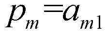 , m=0、 1、 2...M-1。 通信数据符号 <^ =ί¾,2 , ^2k+l =a2k+lfi ^ k=0,l , 1。
2
补偿数据符号 c2 =i½,0 , c2k+l=a2k+l 2 , k=0,l , ... , 1。
2
则, 第一干扰系数矩阵可以表示为:

第二干扰系数矩阵可以表示为

其中, 表示时频资源位置( i , j )发送的数据符号对时频资源位置( m , n )发送的数据符号的干扰系数值。
频域信道系数矩阵表示为:

表示在第一时频资源位置对应的子载波 m上的频域信道系数。 因此, 通过 + Mc c=0可以计算得到补偿数据符号。 在进行信道估计时, 不考虑解调噪声的情况下:
 其中, 表示在第一时频资源位置对应的多载波符号中第 m个子载波 上的接收数据符号, 表示在第 m个子载波上的发送导频数据符号, 表 示第 m个子载波上的信道估计值。
由于通信数据符号以及补偿数据符号对导频数据符号的干扰相抵消,在每 一子载波上的导频数据符号的导频干扰项也为 0,从而可以得到每一子载波上 的信道估计值:
其中, 表示在第一时频资源位置对应的多载波符号中第 m个子载波 上的接收数据符号, 表示在第 m个子载波上的发送导频数据符号, 表 示第 m个子载波上的信道估计值。
由于通信数据符号以及补偿数据符号对导频数据符号的干扰相抵消,在每 一子载波上的导频数据符号的导频干扰项也为 0,从而可以得到每一子载波上 的信道估计值:
Λ
Hm - Hm。 其中, 第一干扰系数矩阵以及第二干扰系数矩阵, 系统可以根据第一时频 资源位置以及第二时频资源位置预先设置。
由于第一时频资源位置以及第二时频资源位置的分布可以有多种可能的 实现方式, 因此, 系统还可以预先设置对应第一时频资源位置以及第二时频资 源位置多种不同分布的干扰系数矩阵,从而在发送导频时, 可以根据当前确定 的第一时频资源位置以及第二时频资源位置,查找与之对应的第一干扰系数矩 阵以及第二干扰系数矩阵。
当然,系统还可以根据当前确定的第一时频资源位置以及第二时频资源位 置, 以及多路复用转换器响应或干扰系数表,分别构造第一干扰系数矩阵以及 第二干扰系数矩阵。
需要说明的是,本发明并不对第一时频资源位置以及第二时频资源位置的 分布, 以及第二时频资源位置中第一集合以及第二集合的确定进行限定,保证 在时频资源位置上发送的通信数据符号以及补偿数据符号分别与导频数据符 号的个数相等, 同时保证第二干扰系数矩阵是可逆矩阵, 以及第二干扰系数矩 阵的逆矩阵和第一干扰系数矩阵的乘积是可逆矩阵即可。
本发明实施例中, 通过确定 M个第一时频资源位置以及 M个第一时频资 源位置的预设邻域中 S个第二时频资源位置, 并在 M个第一时频资源位置发 送导频数据符号;由 S个第二时频资源位置中的第一集合的时频资源位置发送 通信数据符号, 以及第二集合的时频资源位置发送补偿数据符号, 其中, 通信 数据符号和补偿数据符号对导频数据符号的干扰相抵消 ,从而接收端进行信道 因此导频干扰项为 0,接收到数据较干净,从而可以获得较准确的信道估计值。
且利用构造的导频序列可以传输发送端与接收端之间的部分通信数据,从 而根据导频序列中的通信数据符号和补偿数据符号可以解调出发送端发送的 部分通信数据, 提高了数据解调性能, 充分利用了导频资源。 图 3为本发明实施例提供的一种数据接收方法一个实施例的流程图,所述 方法可以包括以下几个步骤:
301 : 接收端在导频序列映射的时频资源位置接收数据符号。
其中, 所述导频序列具有 M个第一时频资源位置以及 S个第二时频资源 位置, 所述 S个第二时频资源位置位于所述 M个第一时频资源位置的预设邻 域中, S=2M; 所述 S个第二时频资源位置中, S/2个第二时频资源位置为第 一集合, 不包括所述第一位置集合的 S/2个第二时频资源位置为第二集合; 发 送端在所述 M个第一时频资源位置发送所述导频数据符号, 在所述第一集合 中的 S/2 个第二时频资源位置发送所述通信数据符号以及在所述第二集合的 S/2个第二时频资源位置发送所述补偿数据符号, 所述通信数据符号与所述补 偿数据符号对所述导频数据符号的干扰相抵消。
302: 根据接收到的接收数据符号以及所述导频数据符号, 进行信道估计, 获得信道估计值。
发送端在第一时频资源位置发送导频数据符号,在第二时频资源位置的第 一集合中的时频资源位置发送通信数据符号,第二集合中的时频资源位置发送 补偿数据符号。
在不考虑解调噪声的情况下, 信道估计值即为:
 其中, 表示在多载波符号的第 m个子载波上的接收数据符号, /^表
Λ
示在第 m个子载波上发送的导频数据符号, 表示第 m个子载波上的信道 估计值。
由于通信数据符号以及补偿数据符号对导频数据符号的干扰相抵消,在每 一子载波上的导频数据符号的导频干扰项也为 0,从而可以得到每一子载波上
的信道估计值:
Hm - Hm。
Hm表示在多载波符号中的子载波 m的频域信道系数。
303: 利用所述信道估计值, 根据在所述第一集合中的第二时频资源位置 解调出的数据和 /或在所述第二集合中的第二时频资源位置解调出的数据, 获 取所述通信数据符号对应的通信数据。
发送端发送的通信数据符号可以为是发送端以及接收端通信过程中传输 的数据符号,而补偿数据符号是利用通信数据符号计算得到的数据符号。因此, 接收端利用信道估计值 ,可以将在通信数据符号映射的时频资源位置接收到的 数据符号进行解调 ,得到的第一解调数据即可以作为通信数据符号对应的通信 数据;
也可以将在补偿数据符号映射的时频资源位置接收到的数据符号进行解 调, 根据得到的补偿解调数据, 可以计算得到通信数据符号对应的通信数据。
即利用所述补偿解调数据,以及所述通信数据符号和所述补偿数据符号对 所述导频数据符号的干扰系数 , 计算得到所述通信数据符号的第二解调数据 , 第二解调数据也可以作为发送端发送的通信数据符号对应通信数据。
具体的, 根据通信数据符号与补偿数据符号的关系 ^^ d + Mc c=0 , 可 以确定出补偿解调数据与第二解调数据的关系, 即:
Md d+ Mc c=0
Md表示由所述通信数据符号对所述导频数据符号造成干扰的干扰系数 构成的第一干扰系数矩阵, Mc表示由所述补偿数据符号对所述导频数据符号 的干扰系数构成的第二干扰系数矩阵, d表示第二解调数据, c表示补偿解调 数据。
其中, 第一干扰系数矩阵以及第二干扰系数矩阵可以是系统预先设置, 或 者由发送端发送的 ,或者由接收端根据接收到导频序列以及多路复用转换器响
应或干扰系数表构造的。
根据解调出的补偿解调数据, 按照上式, 即可以计算得到第二解调数据, 第二解调数据也可以作为通信数据符号对应的通信数据。
当然, 在又一种可能实现方式中, 为了降低干扰和噪声的影响, 提高接收 数据的 SNR ( Signal to Noise Ratio, 信噪比), 提高系统解调性能, 可以分别 解调出第一解调数据以及补偿解调数据,并利用补偿解调数据计算得到的第二 解调数据; 加权合并所述第一解调数据以及所述第二解调数据,得到所述通信 数据符号对应的通信数据, 其中加权合并系数之和为 1 , 不失一般性, 可分别 选择为 1/2。
在本发明实施例中,由于发送端发送的通信数据符号以及补偿数据符号对 导频数据符号的干扰相抵消, 即导频干扰项为 0, 使得可以获得较干净的接收 数据, 从而可以得到准确的信道估计值。
且利用构造的导频序列可以传输发送端与接收端之间的部分通信数据,从 而根据导频序列中的通信数据符号和补偿数据符号可以解调出发送端发送的 部分通信数据, 提高了数据解调性能, 充分利用了导频资源, 从而可以在一定 程度上降低导频开销。 对于前述的各方法实施例, 为了简单描述,故将其都表述为一系列的动作 组合,但是本领域技术人员应该知悉,本发明并不受所描述的动作顺序的限制, 因为依据本发明, 某些步骤可以釆用其他顺序或者同时进行。 其次, 本领域技 术人员也应该知悉,说明书中所描述的实施例均属于优选实施例, 所涉及的动 作和模块并不一定是本发明所必须的。 图 4为本发明实施例提供的一种数据发送装置一个实施例的结构示意图, 所述装置可以包括:
第一确定模块 401 , 用于在时频资源中, 确定 M个第一时频资源位置以 及在所述 M个第一时频资源位置的预设邻域中的 S个第二时频资源位置, 其 中, S=2M;
第二确定模块 402, 用于确定所述 S个第二时频资源位置中, S/2个第二
时频资源位置为第一集合,以及不包括所述第一集合中的第二时频资源位置的 S/2个第二时频资源位置为第二集合;
卜偿数据计算模块 403 , 用于确定在所述第一集合中的第二时频资源位置 发送的通信数据符号,并根据所述通信数据符号计算在所述第二集合中的第二 时频资源位置发送的补偿数据符号,所述通信数据符号以及所述补偿数据符号 对所述导频数据符号的干扰相抵消;
导频发送模块 404, 用于分别在所述 M个第一时频资源位置发送所述导 频数据符号,在所述第一集合中的第二时频资源位置发送所述通信数据符号以 及在所述第二集合中的第二时频资源位置发送所述补偿数据符号。
通信数据符号是发送端以及接收端通信过程中需要传输的数据符号。 由于通信数据符号以及补偿数据符号对导频数据符号的干扰相抵消 ,使得 接收端能够获得较干净的接收数据,从而可以准确实现信道估计,且发送端发 送导频的过程中, 同时发送了通信数据符号,使得接收端可以接收到部分通信 数据, 提高了数据解调性能, 充分利用了导频资源, 因此可以降低导频开销。
其中, 第一确定模块在所述 M个第一时频资源位置的预设邻域中确定 S 个第二时频资源位置可以有多种实现方式。
该第一确定模块 401确定在所述 M个第一时频资源位置的预设邻域中的 S个第二时频资源位置可以是:
确定对所述 M个第一时频资源位置造成干扰的 S个第二时频资源位置。 在一种可能实现方式中, 第一确定模块 401确定对所述 M个第一时频资 源位置造成干扰的 S个第二时频资源位置可以是根据多路复用转换器响应,在 所述 M个第一时频资源位置的多路复用转换器响应的第一预设范围对应的时 频资源位置, 确定 S个第二时频资源位置。
在另一种可能实现方式中, 第一确定模块 401确定对所述 M个第一时频 资源位置造成干扰的 S个第二时频资源位置可以是根据干扰系数表,在所述 M 个第一时频资源位置的干扰系数表的第二预设范围对应的时频资源位置,确定 S个第二时频资源位置;
在又一种可能实现方式中, 第一确定模块 401确定对所述 M个第一时频
资源位置造成干扰的 S 个第二时频资源位置可以是根据系统预置参数确定与 所述 M个第一时频资源位置造成干扰的 S个时频资源位置。
其中, 多路复用转换器响应以及干扰系数表可以参见方法实施例中所述, 在此不再赘述。
其中, 所述 M个第一时频资源位置可以对应 N个连续多载波符号, 对应
M/N个连续子载波;
所述 S个第二时频资源位置可以对应 T个多载波符号,对应 S/T个子载波; 其中, 所述 T个多载波符号为与 N个连续多载波符号编号前后相邻的编 号对应的多载波符号 M/N=S/T; 或者,
T=N, 所述 T个多载波符号为所述 N个多载波符号, 在每个多载波符号 中,第二时频资源位置对应的 S/T个子载波为与第一时频资源位置对应的 M/N 个子载波编号前后相邻的编号对应的子载波。 图 5 示出了本发明实施例提供的一种数据发送装置另一个实施例的结构 示意图, 其中, 第一确定模块 401、 第二确定模块 402、 补偿数据计算模块 403 以及导频发送模块 404可以参见图 4所示实施例,与图 4所示实施例不同之处 在于, 所述补偿数据计算模块 403可以包括:
确定单元 501 , 用于确定在所述第一集合中的第二时频资源位置发送的通 信数据符号
第一获取单元 502, 用于获取由所述第一集合中的第二时频资源位置对所 述 M个第一时频资源位置造成干扰的干扰系数构成的第一干扰系数矩阵; 第二获取单元 503 , 用于获取由所述第二集合中的第二时频资源位置对所 述 M个第一时频资源位置造成干扰的干扰系数构成的第二干扰系数矩阵; 计算单元 504, 用于根据所述通信数据符号、 所述第一干扰系数矩阵以及 所述第二干扰系数矩阵,计算获得补偿数据符号,使得通信数据符号以及所述 补偿数据符号对所述导频数据符号的干扰相抵消。
其中, 该计算单元 504可以具体用于根据所述通信数据符号、所述第一干 扰系数矩阵以及所述第二干扰系数矩阵,按照下述计算公式计算获得补偿数据
符号:
Md d + Mc c= 其中, ^表示第一干扰系数矩阵, 表示第二干扰系数矩阵, d表示 第一集合中的通信数据符号集合, c表示第二集合中的补偿数据符号集合。
其中, 第一干扰系数矩阵以及第二干扰系数矩阵, 系统可以根据第一时频 资源位置以及第二时频资源位置预先设置。
由于第一时频资源位置以及第二时频资源位置的分布可以有多种可能的 实现方式, 因此, 系统还可以预先设置对应多种不同第一时频资源位置以及第 二时频资源位置分布的干扰系数矩阵,从而在发送导频时, 可以根据当前确定 的第一时频资源位置以及第二时频资源位置,查找与之对应的第一干扰系数矩 阵以及第二干扰系数矩阵。
当然,系统还可以根据当前确定的第一时频资源位置以及第二时频资源位 置, 以及多路复用转换器响应或干扰系数表, 分别构造第一干扰系数矩阵以 及第二干扰系数矩阵。 需要说明的是, 本发明并不对导频数据符号、通信数据符号以及补偿数据 符号的时频资源位置分布进行具体限定, 其可以按照图 la〜图 le所示进行分 布, 当然也可以釆用其他分布方式。保证通信数据符号以及补偿数据符号分别 与导频数据符号的个数相等。
上述实施例所述数据发送装置, 在实际应用中, 可以集成到设备中, 该设 备可以为多载波系统中的基站、 终端等, 该多载波系统具体可以是指 FBMC 系统。部署本发明实施例数据发送装置的设备,可以获得较准确的信道估计值。 能够充分利用了导频资源, 避免导频资源的浪费。
通过以上描述可知,本领域的技术人员可以清楚地了解到本发明可借助软 件加必需的通用硬件平台的方式来实现。 因此, 参见图 6所示, 本发明实施例 还提供了一种数据发送设备, 其特征在于, 包括存储器 601、 发送器 602以及 处理器 603 ,
所述存储器 601存储一组程序指令;
所述处理器 603调整所述存储器 601存储的程序指令, 执行如下操作: 在时频资源中, 确定 M个第一时频资源位置以及在所述 M个第一时频资 源位置的预设邻域中的 S个第二时频资源位置, 其中, S=2M;
确定所述 S个第二时频资源位置中, S/2个第二时频资源位置为第一集合, 以及不包括所述第一集合中的第二时频资源位置的 S/2个第二时频资源位置为 第二集合;
确定在所述第一集合中的第二时频资源位置发送的通信数据符号,并根据 所述通信数据符号计算在所述第二集合中的第二时频资源位置发送的补偿数 相 4氏消;
触发所述发送器 602分别在所述 M个第一时频资源位置发送所述导频数 据符号 ,在所述第一集合中的第二时频资源位置发送所述通信数据符号以及在 所述第二集合中的第二时频资源位置发送所述补偿数据符号。 图 7为本发明实施例提供的一种数据接收装置一个实施例的结构示意图, 所述装置可以包括:
接收模块 701 , 用于在导频序列映射的时频资源位置接收数据符号。
其中, 所述导频序列具有 M个第一时频资源位置以及 S个第二时频资源 位置, 所述 S个第二时频资源位置位于所述 M个第一时频资源位置的预设邻 域中, S=2M; 所述 S个第二时频资源位置中, S/2个第二时频资源位置为第 一集合, 不包括所述第一位置集合的 S/2个第二时频资源位置为第二集合; 发 送端在所述 M个第一时频资源位置发送所述导频数据符号, 在所述第一集合 中的 S/2 个第二时频资源位置发送所述通信数据符号以及在所述第二集合的 S/2个第二时频资源位置发送所述补偿数据符号, 所述通信数据符号与所述补 偿数据符号对所述导频数据符号的干扰相抵消。
信道估计模块 702 , 用于根据接收到的接收数据符号以及所述导频数据符 号, 进行信道估计, 获得信道估计值。
数据解调模块 703 , 用于利用所述信道估计值, 根据在所述第一集合中的
第二时频资源位置解调出的数据和 /或在所述第二集合中的第二时频资源位置 解调出的数据, 获取所述通信数据符号对应的通信数据。
接收端利用信道估计值,可以将在通信数据符号映射的时频资源位置接收 到的数据符号进行解调 ,得到的第一解调数据即可以作为通信数据符号对应通 信数据;
也可以在补偿数据符号映射的时频资源位置接收到的数据符号进行解调, 根据得到的补偿解调数据 , 计算得到通信数据符号对应的通信数据。
即利用所述补偿解调数据,以及所述通信数据符号和所述补偿数据符号对 所述导频数据符号的干扰系数,计算得到所述通信数据符号的第二解调数据; , 第二解调数据也可以作为发送端发送的通信数据符号对应通信数据。
具体的, 根据通信数据符号与补偿数据符号的关系 ^^ d + Mc c=0 , 可 以确定出 偿解 数据与第二解调数据的关系, 即:
M, a d+ M c c= 表示由所述通信数据符号对所述导频数据符号造成干扰的干扰系数 构成的第一干扰系数矩阵, Mc表示由所述补偿数据符号对所述导频数据符号 的干扰系数构成的第二干扰系数矩阵, d表示第二解调数据, c表示补偿解调 数据。
其中, 第一干扰系数矩阵以及第二干扰系数矩阵可以是系统预先设置, 或 者由发送端发送的,或者由接收端根据接收到导频序列以及多路复用转换器响 应或干扰系数表构造的。
根据解调出的补偿解调数据, 可以计算得到第二解调数据, 第二解调数据 也可以作为通信数据符号对应的通信数据。
为了降低干扰和噪声的影响, 提高接收数据的 SNR, 提高系统解调性能。 在又一种可能实现方式中, 所述数据解调模块可以包括:
解调单元, 用于利用所述信道估计值, 分别在所述第一集合中的第二时频 资源位置解调出所述通信数据符号的第一解调数据 ,以及在所述第二集合中的 第二时频资源位置解调出所述补偿数据符号的补偿解调数据;
第一计算单元, 用于利用所述补偿解调数据, 以及所述通信数据符号和所 述补偿数据符号对所述导频数据符号的干扰系数,计算得到所述通信数据符号 的第二解调数据;
第二计算单元, 用于加权合并所述第一解调数据以及所述第二解调数据, 得到所述通信数据符号对应的通信数据。
其中加权合并系数之和为 1 , 不失一般性, 可分别选择为 1/2。 即通信数 据等于 1/2的第一解调数据以及 1/2的第二解调数据的和值。
在本发明实施例中,由于发送端发送的通信数据符号以及补偿数据符号对 导频数据符号的干扰相抵消, 即导频干扰项为 0, 从而直接根据接收到数据符 号以及导频数据符号, 可以实现准备的信道估计, 得到准确的信道估计值。
且利用构造的导频序列可以传输发送端与接收端之间的部分通信数据,从 而根据导频序列中的通信数据符号和补偿数据符号可以解调出发送端发送的 部分通信数据, 提高了数据解调性能, 充分利用了导频资源, 从而可以在一定 程度上降低导频开销。
上述实施例所述数据接收装置, 在实际应用中, 可以集成到设备中, 该设 备可以为多载波系统中的基站、 终端等, 该多载波系统具体可以是指 FBMC 系统。部署本发明实施例数据发送装置的设备,可以获得较准确的信道估计值。 充分利用了导频资源, 避免了导频资源的浪费。
通过以上描述可知,本领域的技术人员可以清楚地了解到本发明可借助软 件加必需的通用硬件平台的方式来实现。 因此, 参见图 8所示, 本发明实施例 还提供了一种数据接收设备, 其特征在于, 包括存储器 801、 接收器 802以及 处理器 803 ,
所述存储器 801存储一组程序指令;
所述处理器 803用于调用所述存储器 801存储的程序指令,执行如下操作: 触发所述接收器 802 在导频序列映射的时频资源位置接收数据符号; 其 中, 所述导频序列具有 M个第一时频资源位置以及 S个第二时频资源位置, 所述 S个第二时频资源位置位于所述 M个第一时频资源位置的预设邻域中,
S=2M; 所述 S个第二时频资源位置中, S/2个第二时频资源位置为第一集合, 不包括所述第一位置集合的 S/2个第二时频资源位置为第二集合; 发送端在所 述 M个第一时频资源位置发送所述导频数据符号, 在所述第一集合中的 S/2 个第二时频资源位置发送所述通信数据符号以及在所述第二集合的 S/2个第二 时频资源位置发送所述补偿数据符号 ,所述通信数据符号与所述补偿数据符号 对所述导频数据符号的干扰相抵消;
根据接收到的接收数据符号以及所述导频数据符号, 进行信道估计, 获得 信道估计值;
利用所述信道估计值,根据在所述第一集合中的第二时频资源位置解调出 的数据和 /或在所述第二集合中的第二时频资源位置解调出的数据, 获取所述 通信数据符号对应的通信数据。
本说明书中各个实施例釆用递进的方式描述,每个实施例重点说明的都是 与其他实施例的不同之处,各个实施例之间相同相似部分互相参见即可。对于 实施例公开的装置而言, 由于其与实施例公开的方法相对应, 所以描述的比较 简单, 相关之处参见方法部分说明即可。
最后, 还需要说明的是, 在本文中, 诸如第一和第二等之类的关系术语仅 仅用来将一个实体或者操作与另一个实体或操作区分开来,而不一定要求或者 暗示这些实体或操作之间存在任何这种实际的关系或者顺序。 而且, 术语 "包 括"、 "包含"或者其任何其他变体意在涵盖非排他性的包含, 从而使得包括一 系列要素的过程、 方法、 物品或者设备不仅包括那些要素, 而且还包括没有明 确列出的其他要素, 或者是还包括为这种过程、 方法、 物品或者设备所固有的 要素。 在没有更多限制的情况下, 由语句 "包括一个 ... ... " 限定的要素, 并不 排除在包括所述要素的过程、 方法、 物品或者设备中还存在另外的相同要素。
为了描述的方便, 描述以上装置时以功能分为各种单元分别描述。 当然, 在实施本发明时可以把各单元的功能在同一个或多个软件和 /或硬件中实现。
通过以上的实施方式的描述可知,本领域的技术人员可以清楚地了解到本 发明可借助软件加必需的通用硬件的方式来实现。基于这样的理解, 本发明的 技术方案本质上或者说对现有技术做出贡献的部分可以以软件产品的形式体 现出来, 该计算机软件产品可以存储在存储介质中, 如 ROM/RAM、 磁碟、 光
盘等, 包括若干指令用以使得一台计算机设备(可以是个人计算机, 服务器, 或者网络设备等)执行本发明各个实施例或者实施例的某些部分所述的方法。
对所公开的实施例的上述说明,使本领域专业技术人员能够实现或使用本 发明。 对这些实施例的多种修改对本领域的专业技术人员来说将是显而易见 的, 本文中所定义的一般原理可以在不脱离本发明保护范围的情况下,在其它 实施例中实现。 因此, 本发明将不会被限制于本文所示的这些实施例, 而是要 符合与本文所公开的原理和新颖特点相一致的最宽的范围。
+
Claims
1、 一种数据发送方法, 其特征在于, 包括:
发送端在时频资源中, 确定 M个第一时频资源位置以及在所述 M个第一 时频资源位置的预设邻域中的 S个第二时频资源位置, 其中, S=2M;
确定所述 S个第二时频资源位置中, S/2个第二时频资源位置为第一集合, 以及不包括所述第一集合中的第二时频资源位置的 S/2个第二时频资源位置为 第二集合;
确定在所述第一集合中的第二时频资源位置发送的通信数据符号,并根据 所述通信数据符号计算在所述第二集合中的第二时频资源位置发送的补偿数 相抵消;
分别在所述 M个第一时频资源位置发送所述导频数据符号, 在所述第一 集合中的第二时频资源位置发送所述通信数据符号以及在所述第二集合中的 第二时频资源位置发送所述补偿数据符号。
2、 根据权利要求 1所述的方法, 其特征在于, 所述确定在所述 M个第一 时频资源位置的预设邻域中的 S个第二时频资源位置包括:
确定对所述 M个第一时频资源位置造成干扰的 S个第二时频资源位置。
3、 根据权利要求 2所述的方法, 其特征在于, 所述确定对所述 M个第一 时频资源位置造成干扰的 S个时频资源位置包括:
根据多路复用转换器响应, 在所述 M个第一时频资源位置的多路复用转 换器响应的第一预设范围对应的时频资源位置, 确定 S个第二时频资源位置; 或根据干扰系数表, 在所述 M个第一时频资源位置的干扰系数表的第二 预设范围对应的时频资源位置, 确定 S个第二时频资源位置;
或根据系统预置参数确定与所述 M个第一时频资源位置造成干扰的 S个 时频资源位置。
4、 根据权利要求 1~3任一项所述的方法, 其特征在于, 所述 M个第一时 频资源位置对应 N个连续多载波符号, 对应 M/N个连续子载波;
所述 S个第二时频资源位置对应 T个多载波符号, 对应 S/T个子载波; 其中, 所述 T个多载波符号为与 N个连续多载波符号编号前后相邻的编 号对应的多载波符号, M/N=S/T; 或者,
T=N, 所述 T个多载波符号为所述 N个多载波符号, 在每个多载波符号 中,第二时频资源位置对应的 S/T个子载波为与第一时频资源位置对应的 M/N 个子载波编号前后相邻的编号对应的子载波。
5、 根据权利要求 1~4任一项所述的方法, 其特征在于, 所述根据所述通 信数据符号计算在所述第二集合发送的补偿数据符号包括:
获取由所述第一集合中的第二时频资源位置对所述 M个第一时频资源位 置造成干扰的干扰系数构成的第一干扰系数矩阵;
获取由所述第二集合中的第二时频资源位置对所述 M个第一时频资源位 置造成干扰的干扰系数构成的第二干扰系数矩阵;
根据所述通信数据符号、所述第一干扰系数矩阵以及所述第二干扰系数矩 阵,计算获得补偿数据符号,使得通信数据符号以及所述补偿数据符号对所述 导频数据符号的干扰相抵消。
6、 根据权利要求 5所述的方法, 其特征在于, 所述根据所述通信数据符 号、所述第一干扰系数矩阵以及所述第二干扰系数矩阵,计算获得补偿数据符 号包括:
根据所述通信数据符号、所述第一干扰系数矩阵以及所述第二干扰系数矩 阵, 按照下述计算公式计算获得补偿数据符号:
Md d + Mc c= ;
其中, ^表示第一干扰系数矩阵, 表示第二干扰系数矩阵, d表示 第一集合中的通信数据符号集合, c表示第二集合中的补偿数据符号集合。
7、 一种数据接收方法, 其特征在于, 包括:
接收端在导频序列映射的时频资源位置接收数据符号; 其中, 所述导频序 列具有 M个第一时频资源位置以及 S个第二时频资源位置, 所述 S个第二时 频资源位置位于所述 M个第一时频资源位置的预设邻域中, S=2M; 所述 S个 第二时频资源位置中, S/2个第二时频资源位置为第一集合, 不包括所述第一
位置集合的 S/2个第二时频资源位置为第二集合; 发送端在所述 M个第一时 频资源位置发送所述导频数据符号,在所述第一集合中的 S/2个第二时频资源 位置发送所述通信数据符号以及在所述第二集合的 S/2个第二时频资源位置发 送所述补偿数据符号 ,所述通信数据符号与所述补偿数据符号对所述导频数据 符号的干扰相抵消;
根据接收到的接收数据符号以及所述导频数据符号, 进行信道估计, 获得 信道估计值;
利用所述信道估计值,根据在所述第一集合中的第二时频资源位置解调出 的数据和 /或在所述第二集合中的第二时频资源位置解调出的数据, 获取所述 通信数据符号对应的通信数据。
8、 根据权利要求 7所述的方法, 其特征在于, 所述利用所述信道估计值, 根据在所述第一集合中的第二时频资源位置解调出的数据和 /或在所述第二集 合中的第二时频资源位置解调出的数据,获取所述通信数据符号对应的通信数 据包括:
利用所述信道估计值,分别在所述第一集合中的第二时频资源位置解调出 所述通信数据符号的第一解调数据 ,以及在所述第二集合中的第二时频资源位 置解调出所述补偿数据符号的补偿解调数据;
利用所述补偿解调数据,以及所述通信数据符号和所述补偿数据符号对所 述导频数据符号的干扰系数, 计算得到所述通信数据符号的第二解调数据; 加权合并所述第一解调数据以及所述第二解调数据,得到所述通信数据符 号对应的通信数据。
9、 根据权利要求 8所述的方法, 其特征在于, 所述利用所述补偿解调数 据,以及所述通信数据符号和所述补偿数据符号对所述导频数据符号的干扰系 数, 计算得到所述通信数据符号的第二解调数据包括:
利用所述补偿解调数据,以及所述通信数据符号和所述补偿数据符号对导 频数据符号的干扰系数,按照下述计算公式计算得到所述通信数据符号的第二 解调数据:
Md d+ Mc c=
其中, ^表示由所述通信数据符号对所述导频数据符号造成干扰的干扰 系数构成的第一干扰系数矩阵, Mc表示由所述补偿数据符号对所述导频数据 符号造成干扰的干扰系数构成的第二干扰系数矩阵, d表示第一解调数据, c 表示补偿解调数据。
10、 一种数据发送装置, 其特征在于, 包括:
第一确定模块, 用于在时频资源中, 确定 M个第一时频资源位置以及在 所述 M个第一时频资源位置的预设邻域中的 S个第二时频资源位置, 其中, S=2M;
第二确定模块, 用于确定所述 S个第二时频资源位置中, S/2个第二时频 资源位置为第一集合, 以及不包括所述第一集合中的第二时频资源位置的 S/2 个第二时频资源位置为第二集合; 补偿数据计算模块,用于确定在所述第一集合中的第二时频资源位置发送 的通信数据符号,并根据所述通信数据符号计算在所述第二集合中的第二时频 资源位置发送的补偿数据符号,所述通信数据符号以及所述补偿数据符号对所 述导频数据符号的干扰相抵消;
导频发送模块, 用于分别在所述 M个第一时频资源位置发送所述导频数 据符号 ,在所述第一集合中的第二时频资源位置发送所述通信数据符号以及在 所述第二集合中的第二时频资源位置发送所述补偿数据符号。
11、 根据权利要求 10所述的装置, 其特征在于, 所述第一确定模块确定 在所述 M个第一时频资源位置的预设邻域中的 S个第二时频资源位置具体是: 确定对所述 M个第一时频资源位置造成干扰的 S个第二时频资源位置。
12、 根据权利要求 11所述的装置, 其特征在于, 所述第一确定模块确定 对所述 M个第一时频资源位置造成干扰的 S个第二时频资源位置具体是: 根据多路复用转换器响应, 在所述 M个第一时频资源位置的多路复用转 换器响应的第一预设范围对应的时频资源位置, 确定 S个第二时频资源位置; 或根据干扰系数表, 在所述 M个第一时频资源位置的干扰系数表的第二 预设范围对应的时频资源位置, 确定 S个第二时频资源位置;
或根据系统预置参数确定与所述 M个第一时频资源位置造成干扰的 S个 时频资源位置。
13、 根据权利要求 10~12任一项所述的装置, 其特征在于, 所述 M个第 一时频资源位置对应 N个连续多载波符号, 对应 M/N个连续子载波;
所述 S个第二时频资源位置对应 T个多载波符号, 对应 S/T个子载波; 其中, 所述 T个多载波符号为与 N个连续多载波符号编号前后相邻的编 号对应的多载波符号 M/N=S/T; 或者,
T=N, 所述 T个多载波符号为所述 N个多载波符号, 在每个多载波符号 中,第二时频资源位置对应的 S/T个子载波为与第一时频资源位置对应的 M/N 个子载波编号前后相邻的编号对应的子载波。
14、根据权利要求 10~13任一项所述的装置, 其特征在于, 所述补偿数据 计算模块包括:
确定单元,用于确定在所述第一集合中的第二时频资源位置发送的通信数 据符号
第一获取单元,用于获取由所述第一集合中的第二时频资源位置对所述 M 个第一时频资源位置造成干扰的干扰系数构成的第一干扰系数矩阵;
第二获取单元,用于获取由所述第二集合中的第二时频资源位置对所述 M 个第一时频资源位置造成干扰的干扰系数构成的第二干扰系数矩阵;
计算单元, 用于根据所述通信数据符号、所述第一干扰系数矩阵以及所述 第二干扰系数矩阵,计算获得补偿数据符号,使得通信数据符号以及所述补偿 数据符号对所述导频数据符号的干扰相抵消。
15、 根据权利要求 14所述的装置, 其特征在于, 所述计算单元具体用于 根据所述通信数据符号、 所述第一干扰系数矩阵以及所述第二干扰系数矩阵, 按照下述计算公式计算获得补偿数据符号:
Md d + Mc c=0
其中, ^表示第一干扰系数矩阵, 表示第二干扰系数矩阵, d表示 第一集合中的通信数据符号集合, c表示第二集合中的补偿数据符号集合。
16、 一种数据发送设备, 其特征在于, 包括存储器、 发送器以及处理器,
所述存储器存储一组程序指令;
所述处理器调整所述存储器存储的程序指令, 执行如下操作:
在时频资源中, 确定 M个第一时频资源位置以及在所述 M个第一时频资 源位置的预设邻域中的 S个第二时频资源位置, 其中, S=2M;
确定所述 S个第二时频资源位置中, S/2个第二时频资源位置为第一集合, 以及不包括所述第一集合中的第二时频资源位置的 S/2个第二时频资源位置为 第二集合;
确定在所述第一集合中的第二时频资源位置发送的通信数据符号,并根据 所述通信数据符号计算在所述第二集合中的第二时频资源位置发送的补偿数 相抵消;
触发所述发送器分别在所述 M个第一时频资源位置发送所述导频数据符 号,在所述第一集合中的第二时频资源位置发送所述通信数据符号以及在所述 第二集合中的第二时频资源位置发送所述补偿数据符号。
17、 一种数据接收装置, 其特征在于, 包括:
接收模块, 用于在导频序列映射的时频资源位置接收数据符号; 其中, 所 述导频序列具有 M个第一时频资源位置以及 S个第二时频资源位置, 所述 S 个第二时频资源位置位于所述 M个第一时频资源位置的预设邻域中, S=2M; 所述 S个第二时频资源位置中, S/2个第二时频资源位置为第一集合, 不包括 所述第一位置集合的 S/2个第二时频资源位置为第二集合; 发送端在所述 M 个第一时频资源位置发送所述导频数据符号,在所述第一集合中的 S/2个第二 时频资源位置发送所述通信数据符号以及在所述第二集合的 S/2个第二时频资 源位置发送所述补偿数据符号,所述通信数据符号与所述补偿数据符号对所述 导频数据符号的干扰相抵消;
信道估计模块, 用于根据接收到的接收数据符号以及所述导频数据符号, 进行信道估计, 获得信道估计值;
数据解调模块, 用于利用所述信道估计值,根据在所述第一集合中的第二 时频资源位置解调出的数据和 /或在所述第二集合中的第二时频资源位置解调
出的数据, 获取所述通信数据符号对应的通信数据。
18、 根据权利要求 17所述的装置, 其特征在于, 所述数据解调模块包括: 解调单元, 用于利用所述信道估计值, 分别在所述第一集合中的第二时频 资源位置解调出所述通信数据符号的第一解调数据 ,以及在所述第二集合中的 第二时频资源位置解调出所述补偿数据符号的补偿解调数据;
第一计算单元, 用于利用所述补偿解调数据, 以及所述通信数据符号和所 述补偿数据符号对所述导频数据符号的干扰系数,计算得到所述通信数据符号 的第二解调数据;
第二计算单元, 用于加权合并所述第一解调数据以及所述第二解调数据, 得到所述通信数据符号对应的通信数据。
19、 根据权利要求 18所述的装置, 其特征在于, 所述第一计算单元具体 用于利用所述补偿解调数据,以及所述通信数据符号和所述补偿数据符号对导 频数据符号的干扰系数,按照下述计算公式计算得到所述通信数据符号的第二 解调数据: Md d+ Mc c= 其中, ^表示由所述通信数据符号对所述导频数据符号造成干扰的干扰 系数构成的第一干扰系数矩阵, Mc表示由所述补偿数据符号对所述导频数据 符号造成干扰的干扰系数构成的第二干扰系数矩阵, d表示第一解调数据, c 表示补偿解调数据。
20、 一种数据接收设备, 其特征在于, 包括存储器、 接收器以及处理器; 所述存储器存储一组程序指令;
所述处理器用于调整所述存储器存储的程序指令, 执行如下操作: 触发所述接收器在导频序列映射的时频资源位置接收数据符号; 其中, 所 述导频序列具有 M个第一时频资源位置以及 S个第二时频资源位置, 所述 S 个第二时频资源位置位于所述 M个第一时频资源位置的预设邻域中, S=2M; 所述 S个第二时频资源位置中, S/2个第二时频资源位置为第一集合, 不包括
所述第一位置集合的 S/2个第二时频资源位置为第二集合; 发送端在所述 M 个第一时频资源位置发送所述导频数据符号,在所述第一集合中的 S/2个第二 时频资源位置发送所述通信数据符号以及在所述第二集合的 S/2个第二时频资 源位置发送所述补偿数据符号,所述通信数据符号与所述补偿数据符号对所述 导频数据符号的干扰相抵消;
根据接收到的接收数据符号以及所述导频数据符号, 进行信道估计, 获得 信道估计值;
利用所述信道估计值,根据在所述第一集合中的第二时频资源位置解调出 的数据和 /或在所述第二集合中的第二时频资源位置解调出的数据, 获取所述 通信数据符号对应的通信数据。
+
Priority Applications (4)
| Application Number | Priority Date | Filing Date | Title |
|---|---|---|---|
| PCT/CN2014/080314 WO2015192359A1 (zh) | 2014-06-19 | 2014-06-19 | 数据发送、接收方法、装置及设备 |
| CN201480079266.8A CN106416160B (zh) | 2014-06-19 | 2014-06-19 | 数据发送、接收方法、装置及设备 |
| EP14895317.7A EP3148141B1 (en) | 2014-06-19 | 2014-06-19 | Method, apparatus, and device for transmitting data |
| US15/379,907 US9843463B2 (en) | 2014-06-19 | 2016-12-15 | Data sending method, apparatus, and device, and data receiving method, apparatus, and device |
Applications Claiming Priority (1)
| Application Number | Priority Date | Filing Date | Title |
|---|---|---|---|
| PCT/CN2014/080314 WO2015192359A1 (zh) | 2014-06-19 | 2014-06-19 | 数据发送、接收方法、装置及设备 |
Related Child Applications (1)
| Application Number | Title | Priority Date | Filing Date |
|---|---|---|---|
| US15/379,907 Continuation US9843463B2 (en) | 2014-06-19 | 2016-12-15 | Data sending method, apparatus, and device, and data receiving method, apparatus, and device |
Publications (1)
| Publication Number | Publication Date |
|---|---|
| WO2015192359A1 true WO2015192359A1 (zh) | 2015-12-23 |
Family
ID=54934712
Family Applications (1)
| Application Number | Title | Priority Date | Filing Date |
|---|---|---|---|
| PCT/CN2014/080314 Ceased WO2015192359A1 (zh) | 2014-06-19 | 2014-06-19 | 数据发送、接收方法、装置及设备 |
Country Status (4)
| Country | Link |
|---|---|
| US (1) | US9843463B2 (zh) |
| EP (1) | EP3148141B1 (zh) |
| CN (1) | CN106416160B (zh) |
| WO (1) | WO2015192359A1 (zh) |
Families Citing this family (7)
| Publication number | Priority date | Publication date | Assignee | Title |
|---|---|---|---|---|
| KR102299663B1 (ko) * | 2015-02-24 | 2021-09-08 | 삼성전자 주식회사 | 이동 통신 시스템에서 동기화 방법 및 장치 |
| CN106302300B (zh) * | 2015-06-24 | 2020-07-31 | 北京三星通信技术研究有限公司 | 一种基于滤波器组多载波系统的信号发送和接收的方法及装置 |
| CN107404372B (zh) * | 2016-05-20 | 2019-02-22 | 北京小米移动软件有限公司 | 一种通信方法及装置 |
| JPWO2018083924A1 (ja) * | 2016-11-01 | 2019-08-08 | 日本電気株式会社 | 基地局、端末装置、方法、プログラム、及び記録媒体 |
| CN110120860B (zh) * | 2018-02-06 | 2020-06-30 | 上海朗帛通信技术有限公司 | 一种被用于无线通信的用户设备、基站中的方法和装置 |
| CN113767603B (zh) * | 2019-04-30 | 2022-11-04 | 华为技术有限公司 | 一种通信方法及通信装置 |
| US11445518B2 (en) * | 2019-11-25 | 2022-09-13 | Qualcomm Incorporated | Methods and apparatus for adaptive whitening |
Citations (4)
| Publication number | Priority date | Publication date | Assignee | Title |
|---|---|---|---|---|
| CN101043479A (zh) * | 2006-03-22 | 2007-09-26 | 松下电器产业株式会社 | 正交频分复用系统中的信道估计方法 |
| CN101110630A (zh) * | 2006-07-19 | 2008-01-23 | 鼎桥通信技术有限公司 | 消除下行导频时隙信号干扰的方法及装置 |
| CN101997805A (zh) * | 2009-08-26 | 2011-03-30 | 华为技术有限公司 | 导频符号的处理方法和装置 |
| CN102761506A (zh) * | 2011-04-29 | 2012-10-31 | 扬智科技股份有限公司 | 消除符号间干扰的方法及其装置 |
Family Cites Families (11)
| Publication number | Priority date | Publication date | Assignee | Title |
|---|---|---|---|---|
| ATE444566T1 (de) * | 2005-10-26 | 2009-10-15 | France Telecom | Verfahren zum senden eines mehrträgersignals, das für die begrenzung von störungen ausgelegt ist, signal, emssionseinrichtung, empfangsverfahren und einrichtung und entsprechende computerprogramme |
| WO2008007028A2 (fr) * | 2006-07-12 | 2008-01-17 | France Telecom | Procédés de réception et d'émission d'un signal multiporteuse comprenant un préambule comprenant des éléments de données, dispositifs et produits programme d'ordinateur correspondants |
| JP4405491B2 (ja) * | 2006-09-12 | 2010-01-27 | 株式会社東芝 | Ofdm信号の受信方法及び受信機 |
| CN102130864A (zh) * | 2010-01-20 | 2011-07-20 | 中兴通讯股份有限公司 | 一种信道估计方法和装置 |
| JP5565165B2 (ja) * | 2010-07-21 | 2014-08-06 | 富士通株式会社 | Ofdm通信受信装置 |
| US8660433B2 (en) * | 2010-12-10 | 2014-02-25 | Alcatel Lucent | Pilot-assisted data transmission in a coherent optical-communication system |
| CN103166891A (zh) * | 2011-12-14 | 2013-06-19 | 中国科学院上海微系统与信息技术研究所 | 基于虚拟导频的用于限幅ofdm系统的信道估计方法 |
| CN103312645B (zh) * | 2013-06-05 | 2016-04-13 | 华中科技大学 | 一种数字相干光通信系统的损伤自适应补偿方法及系统 |
| CN105229963B (zh) * | 2013-06-14 | 2018-11-16 | 华为技术有限公司 | 基于滤波器组的用于发射多载波信号的多载波发射器 |
| CN106165360B (zh) * | 2014-04-08 | 2019-06-07 | 杜塞尔多夫华为技术有限公司 | 用于滤波器组多载波通信的发射机、接收机以及系统 |
| EP3151498B1 (en) * | 2014-06-26 | 2019-11-20 | Huawei Technologies Co. Ltd. | Fbmc-based pilot sending method, channel estimating method and related devices |
-
2014
- 2014-06-19 EP EP14895317.7A patent/EP3148141B1/en not_active Not-in-force
- 2014-06-19 WO PCT/CN2014/080314 patent/WO2015192359A1/zh not_active Ceased
- 2014-06-19 CN CN201480079266.8A patent/CN106416160B/zh active Active
-
2016
- 2016-12-15 US US15/379,907 patent/US9843463B2/en not_active Expired - Fee Related
Patent Citations (4)
| Publication number | Priority date | Publication date | Assignee | Title |
|---|---|---|---|---|
| CN101043479A (zh) * | 2006-03-22 | 2007-09-26 | 松下电器产业株式会社 | 正交频分复用系统中的信道估计方法 |
| CN101110630A (zh) * | 2006-07-19 | 2008-01-23 | 鼎桥通信技术有限公司 | 消除下行导频时隙信号干扰的方法及装置 |
| CN101997805A (zh) * | 2009-08-26 | 2011-03-30 | 华为技术有限公司 | 导频符号的处理方法和装置 |
| CN102761506A (zh) * | 2011-04-29 | 2012-10-31 | 扬智科技股份有限公司 | 消除符号间干扰的方法及其装置 |
Non-Patent Citations (1)
| Title |
|---|
| See also references of EP3148141A4 * |
Also Published As
| Publication number | Publication date |
|---|---|
| CN106416160A (zh) | 2017-02-15 |
| EP3148141A1 (en) | 2017-03-29 |
| CN106416160B (zh) | 2020-03-10 |
| EP3148141A4 (en) | 2017-06-21 |
| US9843463B2 (en) | 2017-12-12 |
| US20170099164A1 (en) | 2017-04-06 |
| EP3148141B1 (en) | 2020-06-24 |
Similar Documents
| Publication | Publication Date | Title |
|---|---|---|
| WO2015192359A1 (zh) | 数据发送、接收方法、装置及设备 | |
| JP5803795B2 (ja) | 受信装置、周波数偏差算出方法及びコンピュータプログラム | |
| JP5042361B2 (ja) | 通信システム、送信機、受信機及び通信方法 | |
| JP5445677B2 (ja) | 送信機、受信機、通信システム、通信方法 | |
| CN106464629A (zh) | 一种基于fbmc的导频发送方法、信道估计方法及相关装置 | |
| WO2014206348A1 (zh) | 一种fbmc系统中同步信号的发送方法和装置 | |
| WO2016078303A1 (zh) | 数据传输方法及装置 | |
| KR20170060112A (ko) | 다중 사용자 코드 분할 다중 접속 통신 방법 및 상응한 송신기, 수신기 | |
| CN104394105B (zh) | Tds‑ofdm信道估计均衡方法及系统 | |
| WO2014067416A1 (zh) | 干扰信号重构方法和终端 | |
| CN114095140B (zh) | 信号处理方法和设备 | |
| CN106160787A (zh) | 一种数据传输方法及装置 | |
| CN102437995A (zh) | 基于逐码片迭代检测的迭代载波同步方法及系统 | |
| JP6065100B2 (ja) | 無線通信システムにおける受信装置およびチャネル推定制御方法 | |
| CN108632002B (zh) | 一种无线通信中的信号发送方法、接收方法、装置和系统 | |
| CN104253771B (zh) | 多参数联合估计方法和装置 | |
| JP2020036106A (ja) | ユーザ端末および無線基地局 | |
| WO2012109928A1 (zh) | 信号处理方法、装置及系统 | |
| CN104205694A (zh) | 信道估计方法和接收机 | |
| JP5662955B2 (ja) | 受信装置、及び受信方法 | |
| CN108605028B (zh) | 用于在无线通信系统中估计和校正相位误差的方法和装置 | |
| JP2010161648A (ja) | 通信システム、送信装置、受信装置、送信制御方法、受信制御方法、送信制御プログラム、受信制御プログラム | |
| CN104396175B (zh) | 一种检测上行控制信道上发送的信号的方法、装置和设备 | |
| CN103427873B (zh) | 干扰的消除方法及装置 | |
| JP2012521124A5 (zh) |
Legal Events
| Date | Code | Title | Description |
|---|---|---|---|
| 121 | Ep: the epo has been informed by wipo that ep was designated in this application |
Ref document number: 14895317 Country of ref document: EP Kind code of ref document: A1 |
|
| NENP | Non-entry into the national phase |
Ref country code: DE |
|
| REEP | Request for entry into the european phase |
Ref document number: 2014895317 Country of ref document: EP |
|
| WWE | Wipo information: entry into national phase |
Ref document number: 2014895317 Country of ref document: EP |