WO2015193936A1 - 成形品の離型支援装置 - Google Patents
成形品の離型支援装置 Download PDFInfo
- Publication number
- WO2015193936A1 WO2015193936A1 PCT/JP2014/065862 JP2014065862W WO2015193936A1 WO 2015193936 A1 WO2015193936 A1 WO 2015193936A1 JP 2014065862 W JP2014065862 W JP 2014065862W WO 2015193936 A1 WO2015193936 A1 WO 2015193936A1
- Authority
- WO
- WIPO (PCT)
- Prior art keywords
- shaft
- vertical
- pin member
- mold release
- molded product
- Prior art date
- Legal status (The legal status is an assumption and is not a legal conclusion. Google has not performed a legal analysis and makes no representation as to the accuracy of the status listed.)
- Ceased
Links
Images


Classifications
-
- B—PERFORMING OPERATIONS; TRANSPORTING
- B29—WORKING OF PLASTICS; WORKING OF SUBSTANCES IN A PLASTIC STATE IN GENERAL
- B29C—SHAPING OR JOINING OF PLASTICS; SHAPING OF MATERIAL IN A PLASTIC STATE, NOT OTHERWISE PROVIDED FOR; AFTER-TREATMENT OF THE SHAPED PRODUCTS, e.g. REPAIRING
- B29C45/00—Injection moulding, i.e. forcing the required volume of moulding material through a nozzle into a closed mould; Apparatus therefor
- B29C45/17—Component parts, details or accessories; Auxiliary operations
- B29C45/40—Removing or ejecting moulded articles
- B29C45/44—Removing or ejecting moulded articles for undercut articles
-
- B—PERFORMING OPERATIONS; TRANSPORTING
- B29—WORKING OF PLASTICS; WORKING OF SUBSTANCES IN A PLASTIC STATE IN GENERAL
- B29C—SHAPING OR JOINING OF PLASTICS; SHAPING OF MATERIAL IN A PLASTIC STATE, NOT OTHERWISE PROVIDED FOR; AFTER-TREATMENT OF THE SHAPED PRODUCTS, e.g. REPAIRING
- B29C45/00—Injection moulding, i.e. forcing the required volume of moulding material through a nozzle into a closed mould; Apparatus therefor
- B29C45/17—Component parts, details or accessories; Auxiliary operations
- B29C45/26—Moulds
- B29C45/2628—Moulds with mould parts forming holes in or through the moulded article, e.g. for bearing cages
-
- B—PERFORMING OPERATIONS; TRANSPORTING
- B29—WORKING OF PLASTICS; WORKING OF SUBSTANCES IN A PLASTIC STATE IN GENERAL
- B29C—SHAPING OR JOINING OF PLASTICS; SHAPING OF MATERIAL IN A PLASTIC STATE, NOT OTHERWISE PROVIDED FOR; AFTER-TREATMENT OF THE SHAPED PRODUCTS, e.g. REPAIRING
- B29C45/00—Injection moulding, i.e. forcing the required volume of moulding material through a nozzle into a closed mould; Apparatus therefor
- B29C45/17—Component parts, details or accessories; Auxiliary operations
- B29C45/26—Moulds
- B29C45/33—Moulds having transversely, e.g. radially, movable mould parts
Definitions
- the present invention relates to a mold release assisting device for smoothing mold release of manufactured molded articles using various plastic materials as raw materials. Discloses a technology for smoothly and reliably performing a mold release process in the manufacturing process of molded products made of various plastics, especially when forming various plastic products having three-dimensional or complex shapes or structures. In addition, there is a need for an improved technique for producing a desired molded product while shortening the cycle time during injection molding of these plastic molded products as much as possible.
- the mold apparatus that is indispensable for manufacturing various molded products having such complicated shapes or structures inevitably has complicated shapes. Therefore, what is formed as a combination of a plurality of parts is increasing.
- To mold a molded product with a complicated shape or complicated structure prepare a mold with a cavity of the corresponding structure, and after a certain amount of molten resin is injected into the cavity, it is appropriate after the time suitable for the solidification process. Appropriate mold release processing is necessary at appropriate timing.
- connection structure including a female pin receiving portion including a large number of connector pins, such as a component member of a multipolar connector as an electrical connecting member, is also required. Therefore, when manufacturing a female connector, connector pin receivers corresponding to the corresponding number of poles must be formed. When a connector body having an opening with a large total area is formed in response to such a request, a complicated process suitable for each is required.
- Patent Document 1 discloses a mold cavity 2 used for manufacturing a resin molded product, a core 3 that can move relative to the cavity, and a back portion of the core that can move relative to the core.
- the mold apparatus for resin molding which has the inclination slide 6 provided with the slide unit 23 which slides freely the other end side of this with respect to the ejector plate 4 is disclosed.
- the inclined slide 6 has a smaller amount of the inclined core portion 21 protruding from the core 3 than the distance by which the ejector plate 4 advances toward the core 3 when the cavity 2 and the core 3 are separated from each other.
- a protrusion amount restricting means for guiding the inclined pin 22 is provided.
- Patent Document 1 In the tilt slide mechanism disclosed in Patent Document 1, it is not possible to completely prevent the occurrence of bending or breakage of the undercut portion in the mold release process, and it is impossible to prevent the occurrence of defective parts in the molded product itself. Thus, although patent document 1 is disclosing the metal mold
- An object of the present invention is to provide a release support device for a molded product that can smoothly release a molded product to be manufactured using various plastic materials as raw materials.
- Engineering plastics widely recognized as plastic molding materials that is, using high-functional resins as raw materials, for example, when manufacturing various products widely used in electrical and electronic equipment, especially complex equipment,
- the development of a technology that can be manufactured with a minimum number of steps to facilitate mold release is an issue.
- the horizontal portion 14 that forms a right angle with the upper side is formed, and a part of the vertical portion in the vicinity of the upper end portion is vertical.
- 11 and has a horizontal through-hole 13 in the vertical portion, and the inclined shaft 10 formed so that the lower side of the vertical portion is inclined outwardly to become the inclined slide portion 12, and the inclined shaft of the inclined shaft.
- It is a shaft that is formed in parallel with the vertical portion 11 and substantially the same length as the inclined shaft, and is inserted into a horizontal through hole 13 formed in the vertical portion 11 of the inclined shaft so as to be freely movable.
- the vertical portion 11 of the inclined shaft has a shape of a drooping HP and a protrusion PP formed below the molded product MP. It is processed so that it may become a corresponding shape, and the invention according to claim 3 is fixed to the vertical shaft in the mold release assisting device according to claim 1 or 2.
- the pin member 21 and the mechanism for operating the pin member are provided in a number corresponding to the number of protrusions PP with which the pin member tip contacts, and operate simultaneously.
- the position and number of positions of the portion CP where the tip of the pin member contacts in the protrusion PP are It is determined according to the form of the part.
- the form of the protrusion means the shape, length, thickness, width size, etc. of the protrusion.
- the invention according to claim 5 is characterized in that the inclined shaft 10, the vertical shaft 20, and the pin member 21 in the mold release assisting device of the molded product according to any one of claims 1 to 4 are made of metal.
- the inclined shaft, the vertical shaft and the pin member are preferably made of hard metal.
- a mold release assisting device includes a horizontal portion, a vertical portion having a horizontal through hole, an inclined shaft formed so that a lower side of the vertical portion becomes an inclined slide portion, a vertical portion, Since the entire structure is parallel and has a shaft that is formed to have substantially the same length as the inclined shaft, and has a vertical shaft that is inserted into a horizontal through hole and has a pin member that can be freely moved, the structure is simple. The structure can be manufactured, and smooth mold release can be assisted and supported by the operation of the inclined shaft, the vertical shaft and the pin member without using an external control means.
- the inclined shaft and the vertical shaft move up and down at the same time, and the inclined shaft moves closer to the vertical shaft side with the upward movement.
- the tip of the pin member protrudes from the through hole, and the tip of the pin member comes into contact with the pressing object 30 so that the object does not move. Therefore, it is possible to reliably prevent the occurrence of deformation, cracking, bending, breakage, etc., which tends to occur in the mold release process in which the undercut part etc. is formed below the molded product. It becomes possible to carry out.
- the mold release assisting device is processed so that the vertical portion of the inclined slide has a shape corresponding to the shape of the hanging portion and the protrusion formed below the molded product, and is formed into a vertical shaft.
- the fixed pin member and the mechanism for operating the pin member are provided in a corresponding number according to the number of the projecting portions PP with which the pin member tip contacts, and are configured to operate simultaneously.
- the position and the number of positions of the portion CP where the pin member tip of the protrusion PP contacts are determined according to the shape, length, thickness, width size, etc. of the protrusion, It can be applied to various shaped products that are widely used in electrical and electronic equipment and can be used for a wide range of products.
- release support device for molded products according to the present invention
- release support device a configuration example of the release support device according to the present invention and The operation and function of the apparatus at the time of mold release will be described.
- the mold release assisting device reliably and promptly performs the mold release process without hindering the molded product after molding when molding a molded product such as a molded product having a complicated shape, for example, an undercut part ( (Smoothly)
- This is a mold release support device that can be implemented, and when starting the mold release after the molding process is completed, excessive stress that may cause deformation or partial depression of the molded product
- This is a mold release assisting device for supporting smooth mold release without giving any.
- FIG. 1 is a diagram for explaining an example of the basic configuration of a mold release assisting device and the operation and function of the device at the time of mold release.
- FIG. 1A shows an operating state at the start of mold release
- FIG. (C) shows the operating state at the time of the maximum ascent of the shaft.
- the part shown with the chain line in the figure represents the part hidden inside. Expressions such as “upper”, “lower”, “right”, “left”, “upper surface”, “lower surface” are expressed based on directions in the state shown in the drawing.
- the mold release support apparatus is a mold release apparatus for a mold having an inclined slide mechanism, and basically attaches an inclined shaft 10 and a pin member 21 each having a horizontal through-hole 13 as shown in FIG. This is a simple structure constituted by the vertical shaft 20.
- the inclined shaft 10 forms a horizontal portion 14 that is perpendicular to the upper side, and a portion near the upper end portion forms a vertical portion 11 that is vertical.
- a horizontal through hole 13 is opened in the vertical portion in the horizontal direction, and a lower side of the vertical portion is an inclined slide portion 12 that is bent so as to be inclined toward the left outer direction. The bending angle is not strictly specified.
- the upper surface of the horizontal portion 14 is in contact with the cavity portion located above.
- the left side of the vertical part 11 is in contact with the surface of the hanging part HP and the protrusion PP formed below the molded product, and the right side of the vertical part 11 is parallel to the vertical shaft 20.
- the entire vertical direction of the vertical shaft 20 is parallel to the vertical portion 11 of the inclined shaft, and is formed to have substantially the same length as the inclined shaft.
- the inclined shaft has a pin member 21 fixed inside the vicinity of the upper end.
- the pin member 21 has a right end fixed to the inclined shaft, and a left portion in contact with the object 30 to be pressed can be freely moved in the horizontal direction without resistance.
- the through hole 13 is inserted. Conventional means such as screwing or welding can be adopted as the fixing means for the pin member.
- the vertical portion 11 of the inclined slide is processed so as to be the same as the corresponding shape according to the shape of the hanging portion HP and the protrusion PP formed below the molded product MP to which the present invention is applied. Yes.
- the inclined shaft, the vertical shaft, and the pin member are preferably made of metal, and more preferably made of hard metal.
- an elevating guide portion having a guide hole for receiving the inclined shaft and the vertical shaft from the lower side is fixedly disposed in the mold, and the vertical shaft of the inclined shaft is arranged according to the guide of the elevating guide portion. The horizontal movement to the side and the simultaneous raising and lowering movement of the inclined shaft and the vertical shaft are reliably performed.
- FIG. 2 is a diagram for explaining a configuration example in which the mold release assisting device is applied to a molded product in which a hanging portion and a protrusion are formed below, and the operation and function of the device when releasing the molded product
- (A) is the operation state at the time of mold release start
- (B) is the operation state in the middle of a shaft raising
- (C) has shown the operation state at the time of the maximum raise of a shaft.
- the inclined shaft 10 and the vertical shaft 20 move up and down simultaneously in a synchronized state.
- the inclined shaft has a function of an inclined slide mechanism and executes an inclined slide motion.
- the inclined shaft rises in the U direction and moves horizontally in the H direction to approach the vertical shaft side.
- the vertical shaft only moves up and down at the same time as the inclined shaft, and the distance between the hanging part HP and the protrusion PP is unchanged from the start of mold release, and even if the mold goes up as the mold release process proceeds, it moves in the horizontal direction. Do not exercise.
- the tip of the pin member is in contact with the pressing object 30 while penetrating through the horizontal through-hole 13 at the start of mold release. 30 is in contact.
- the mold release support device operates and functions as follows. As shown in FIG. 2 (A), at the start of mold release, the tip direction portion of the pin member is in contact with the tip portion of the projecting portion PP in a state of penetrating the horizontal through hole 13, and between the inclined shaft and the vertical shaft. The interval is the maximum. Thereafter, as shown in FIG. 2B, as the mold release process proceeds, both shafts move upward in the U direction, and the inclined shaft also moves closer to the vertical shaft along with the upward movement. By these movements, the vertical portion 11 of the inclined shaft moves horizontally in the H direction to move away from the hanging portion HP and the protrusion PP, and the tip end of the pin member protrudes from the through hole and contacts the tip of the protrusion PP.
- the vertical portion 11 of the inclined shaft is separated from the hanging portion HP and the protruding portion PP as shown in FIG.
- the tip of the pin member is pressed so that the object to be pressed does not move by continuously contacting the protrusion PP while protruding to the maximum from the through hole.
- the molded product is pushed upward while the tip of the pin member presses the object to be pressed, and the mold release process is completed.
- the release support device assists and supports the release process so that the release process is smoothly performed.
- the contact of the tip of the pin member with the tip of the protrusion is a state where the pressing force is not applied from the pin member side but is merely touched so that the object to be pressed does not move.
- the vertical shaft is moved away from the object 30 to be pressed at the time when both shafts at the time of releasing the maximum rise. It can also be configured to move horizontally.
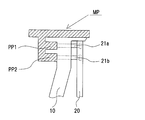
- FIG. 3 is a diagram illustrating a configuration example in which the mold release assisting device is applied to a molded product in which two protrusions are formed below.
- the hatched portion indicates a molded product in which a hanging portion and a protruding portion (undercut portion) are formed below. Since the operation and function of the pin member have been described above, they are omitted here.
- two projections PP1 and PP2 are formed below the molded product MP, and the tip ends of the two pin members 21a and 21b are in contact with the tips of the projections, respectively. ing.
- a mechanism for operating both pin members is configured to operate simultaneously. As described above, until the molded product is pushed upward and the mold release is performed, the tip portions of both pin members are pressed against the projections PP1 and PP2 so that the object to be pressed does not move. . Even in the mold release process of a molded product having two protrusions formed below, the mold release assisting device assists and supports the mold release process so that the mold release process is smoothly performed.
- FIG. 3 shows a molded product in which two (1 in FIG. 2) protrusions (undercut portions) are formed on the lower side.
- the molded product is applied to the present invention.
- the formed product is not limited to these, and the number of protrusions to be formed may be a plurality of three or more, or may be a complex shape such as a multipole connector. In this case, the object can be achieved by providing and operating the number of pin members corresponding to the number of protrusions and a mechanism for simultaneously operating the pins.
- FIG. 4 shows a configuration example of the hanging portion and the protrusion of the mold release assisting device according to the present invention, an arrangement example of a portion where the tip of the pin member contacts, and an example of the arrangement number.
- the hanging part HP and the projecting part PP are L-shaped as a whole, the hanging part is vertically long, the section of the projecting part is linear, and is wide in the lateral direction.
- the part that the tip of the pin member comes into contact with and is pressed is basically determined by the portion that is difficult to come off during mold release and easily breaks in the form formed below the molded product.
- the contact part is arbitrarily determined depending on the shape, length, thickness, width, etc. of the protrusion, and the position and number of positions of the part CP in contact with the tip of the pin member depend on the form of the protrusion. Can be determined.
- the contact portion of the pin member tip (the pin member pressing portion) is located on the tip of the protrusion.
- Two CP1, CP2 are arranged at equal intervals.
- the shape of the protrusion is linear in cross section, but if the cross section is square or curved, the contact part of the tip of the pin member can be placed near the apex of the protrusion, Depending on the width of the width, the number of contact parts can be three or more.
- the timing for executing such a mold release support operation should be an appropriate processing time that is not excessive or deficient in consideration of various conditions such as the type of plastic used as a raw material and the influence of auxiliary materials used, the structure of the molded body, and the ambient temperature. It should be decided in consideration.
- the present invention since it is possible to smoothly release the molded product, it goes without saying that it can contribute to the industry for molding and manufacturing molded products, and resin molded products are used for household appliances, other daily necessities, office supplies, various industrial machines. It is used in a wide range of fields such as equipment, automobiles, railways, airplanes, etc., and the present invention is used for manufacturing molded articles in such fields. It is expected to contribute to a wide range of industrial fields such as manufacturing.
- the present invention improves the problems at the time of molding of resin molded products having excellent functions and characteristics, based on the current situation that the applications of resin molded products are increasing with the improvement of resin itself and the development of molding technology. Thus, it is possible to effectively use engineering plastics in many industrial fields.
Landscapes
- Engineering & Computer Science (AREA)
- Manufacturing & Machinery (AREA)
- Mechanical Engineering (AREA)
- Moulds For Moulding Plastics Or The Like (AREA)
Abstract
Description
11 垂直部位
12 傾斜スライド部位
13 水平貫通孔
14 水平部
20 垂直シャフト
21、21a、21b ピン部材
30 押え付け対象
MP 成形品
HP 垂下部
PP 突起部
CP、CP1、CP2 ピン部材先端部の接触部位
U 上昇方向
H 水平移動方向
Claims (5)
- 傾斜スライド機構を備えた金型における成形品の離型装置において、
上辺に直角をなす水平部を形成し、上端部付近における一部が垂直状の垂直部位を形成し、該垂直部位に水平貫通孔を有し、該垂直部位の下方側が外向き傾斜状に加工され傾斜スライド部位となるように形成された傾斜シャフトと、
前記傾斜シャフトの垂直部位と全体が並行をなし該傾斜シャフトとほぼ同じ長さに形成されたシャフトであって、傾斜シャフトの垂直部位に形成された水平貫通孔に挿通され自由移動可能であるように水平方向に向けて固着されたピン部材を備えた垂直シャフトと、からなり、
前記傾斜シャフトと垂直シャフトは同時に昇降運動し、傾斜シャフトの上昇運動の際の垂直シャフト側への接近移動に伴って、前記水平貫通孔を貫通したピン部材先端が該貫通孔から突き出し、ピン部材先端部が押え付け対象に接触して当該対象が動かないように押え付け、円滑な離型を支援するように構成されたことを特徴とする成形品の離型支援装置。 - 前記傾斜シャフトの垂直部位が、成形品の下方に形成される垂下部および突起部の形状に対応する形状となるように加工される、ことを特徴とする請求項1に記載の成形品の離型支援装置。
- 前記垂直シャフトに固着されたピン部材並びに該ピン部材を作動させるための機構が、ピン部材先端部が接触する前記突起部の数に応じて対応する数だけ設けられ、かつ同時に作動する、ことを特徴とする請求項1又は2のいずれかに記載の成形品の離型支援装置。
- 前記突起部におけるピン部材先端部が接触する部位の位置および配置数が、突起部の形態に応じて決定される、ことを特徴とする請求項1~3のいずれかに記載の成形品の離型支援装置。
- 前記傾斜シャフト、垂直シャフトおよびピン部材が金属製である、ことを特徴とする請求項1~4のいずれかに記載の成形品の離型支援装置。
Priority Applications (3)
| Application Number | Priority Date | Filing Date | Title |
|---|---|---|---|
| PCT/JP2014/065862 WO2015193936A1 (ja) | 2014-06-16 | 2014-06-16 | 成形品の離型支援装置 |
| EP14894913.4A EP3156203B1 (en) | 2014-06-16 | 2014-06-16 | Release assistance device for molded article |
| JP2014555013A JP5762649B1 (ja) | 2014-06-16 | 2014-06-16 | 成形品の離型支援装置 |
Applications Claiming Priority (1)
| Application Number | Priority Date | Filing Date | Title |
|---|---|---|---|
| PCT/JP2014/065862 WO2015193936A1 (ja) | 2014-06-16 | 2014-06-16 | 成形品の離型支援装置 |
Publications (1)
| Publication Number | Publication Date |
|---|---|
| WO2015193936A1 true WO2015193936A1 (ja) | 2015-12-23 |
Family
ID=53887775
Family Applications (1)
| Application Number | Title | Priority Date | Filing Date |
|---|---|---|---|
| PCT/JP2014/065862 Ceased WO2015193936A1 (ja) | 2014-06-16 | 2014-06-16 | 成形品の離型支援装置 |
Country Status (3)
| Country | Link |
|---|---|
| EP (1) | EP3156203B1 (ja) |
| JP (1) | JP5762649B1 (ja) |
| WO (1) | WO2015193936A1 (ja) |
Families Citing this family (1)
| Publication number | Priority date | Publication date | Assignee | Title |
|---|---|---|---|---|
| JP5872120B1 (ja) * | 2015-04-15 | 2016-03-01 | ケンモールドサービス株式会社 | 成形品の離型支援装置 |
Citations (7)
| Publication number | Priority date | Publication date | Assignee | Title |
|---|---|---|---|---|
| JPS5884740A (ja) * | 1981-11-17 | 1983-05-20 | Honda Eng Kk | 合成樹脂成形金型 |
| JPH01228808A (ja) * | 1988-03-09 | 1989-09-12 | Suzuki Motor Co Ltd | 成形装置 |
| JPH0347110U (ja) * | 1989-09-16 | 1991-05-01 | ||
| JPH06126749A (ja) * | 1992-10-14 | 1994-05-10 | Matsushita Electric Ind Co Ltd | 樹脂成形金型装置 |
| JP2001079898A (ja) * | 1999-09-14 | 2001-03-27 | Oiles Ind Co Ltd | スライドコアガイドユニット |
| JP2002137266A (ja) * | 2000-11-07 | 2002-05-14 | Ichikoh Ind Ltd | 樹脂成形用金型装置および樹脂成形方法 |
| JP2003039508A (ja) * | 2001-08-03 | 2003-02-13 | Yazaki Corp | 射出成形金型 |
Family Cites Families (1)
| Publication number | Priority date | Publication date | Assignee | Title |
|---|---|---|---|---|
| US7121823B2 (en) * | 2004-08-24 | 2006-10-17 | Cheng Uei Precision Industry Co., Ltd. | Mold assembly for forming a plastic article having a complicated shape |
-
2014
- 2014-06-16 WO PCT/JP2014/065862 patent/WO2015193936A1/ja not_active Ceased
- 2014-06-16 EP EP14894913.4A patent/EP3156203B1/en active Active
- 2014-06-16 JP JP2014555013A patent/JP5762649B1/ja active Active
Patent Citations (7)
| Publication number | Priority date | Publication date | Assignee | Title |
|---|---|---|---|---|
| JPS5884740A (ja) * | 1981-11-17 | 1983-05-20 | Honda Eng Kk | 合成樹脂成形金型 |
| JPH01228808A (ja) * | 1988-03-09 | 1989-09-12 | Suzuki Motor Co Ltd | 成形装置 |
| JPH0347110U (ja) * | 1989-09-16 | 1991-05-01 | ||
| JPH06126749A (ja) * | 1992-10-14 | 1994-05-10 | Matsushita Electric Ind Co Ltd | 樹脂成形金型装置 |
| JP2001079898A (ja) * | 1999-09-14 | 2001-03-27 | Oiles Ind Co Ltd | スライドコアガイドユニット |
| JP2002137266A (ja) * | 2000-11-07 | 2002-05-14 | Ichikoh Ind Ltd | 樹脂成形用金型装置および樹脂成形方法 |
| JP2003039508A (ja) * | 2001-08-03 | 2003-02-13 | Yazaki Corp | 射出成形金型 |
Also Published As
| Publication number | Publication date |
|---|---|
| EP3156203B1 (en) | 2019-08-07 |
| JPWO2015193936A1 (ja) | 2017-04-20 |
| EP3156203A4 (en) | 2018-05-02 |
| JP5762649B1 (ja) | 2015-08-12 |
| EP3156203A1 (en) | 2017-04-19 |
Similar Documents
| Publication | Publication Date | Title |
|---|---|---|
| KR101286663B1 (ko) | 도어 힌지편 밴딩장치 | |
| CN202021713U (zh) | 内滑块机构 | |
| JP5762649B1 (ja) | 成形品の離型支援装置 | |
| CN205735849U (zh) | 一种塑料变形出模机构 | |
| KR101717026B1 (ko) | 다방향 언더컷 동시 처리용 슬라이드 코어 조립체 | |
| CN105810628A (zh) | 衬底支持装置 | |
| KR200440564Y1 (ko) | 언더컷 성형을 위한 슬라이드 코아장치 | |
| CN103427310A (zh) | 电连接器外壳固定孔冲压成型的方法 | |
| CN110076969B (zh) | 联动型脱模装置及模具设备 | |
| CN109513863B (zh) | 一种插针牙板模具、插针生产工艺以及系统 | |
| CN105351730B (zh) | 一种王字型模压聚合物工件 | |
| CN201922522U (zh) | 斜销顶出机构及射出成型模具 | |
| CN105618747A (zh) | 一次冲压可成型数个带孔产品的模具 | |
| CN202422779U (zh) | 立弯输电母排及母排立弯模具 | |
| CN104972615A (zh) | 注塑模具的斜顶脱模机构 | |
| CN104960150A (zh) | 注塑模具 | |
| CN203973961U (zh) | 带有不同方向倒钩的产品的成型模具 | |
| JP5071221B2 (ja) | 金属板付き成形品の製造方法および金属板付き成形品用の成形型 | |
| CN209812992U (zh) | 延迟滑块 | |
| CN203831703U (zh) | 导向盖模具 | |
| CN204183827U (zh) | 一种注塑模具 | |
| CN103272904A (zh) | 手刹制动杆折弯成型装置 | |
| CN203831738U (zh) | 一种电动车脚踏板注塑模具顶出机构 | |
| CN209832329U (zh) | 一种可视窗面板模具结构 | |
| JP5872120B1 (ja) | 成形品の離型支援装置 |
Legal Events
| Date | Code | Title | Description |
|---|---|---|---|
| ENP | Entry into the national phase |
Ref document number: 2014555013 Country of ref document: JP Kind code of ref document: A |
|
| 121 | Ep: the epo has been informed by wipo that ep was designated in this application |
Ref document number: 14894913 Country of ref document: EP Kind code of ref document: A1 |
|
| REEP | Request for entry into the european phase |
Ref document number: 2014894913 Country of ref document: EP |
|
| WWE | Wipo information: entry into national phase |
Ref document number: 2014894913 Country of ref document: EP |
|
| NENP | Non-entry into the national phase |
Ref country code: DE |