WO2015194024A1 - エネルギーネットワークの熱需要調整装置及びエネルギーネットワークの熱需要調整方法 - Google Patents
エネルギーネットワークの熱需要調整装置及びエネルギーネットワークの熱需要調整方法 Download PDFInfo
- Publication number
- WO2015194024A1 WO2015194024A1 PCT/JP2014/066369 JP2014066369W WO2015194024A1 WO 2015194024 A1 WO2015194024 A1 WO 2015194024A1 JP 2014066369 W JP2014066369 W JP 2014066369W WO 2015194024 A1 WO2015194024 A1 WO 2015194024A1
- Authority
- WO
- WIPO (PCT)
- Prior art keywords
- heat
- demand
- energy network
- energy
- heat source
- Prior art date
- Legal status (The legal status is an assumption and is not a legal conclusion. Google has not performed a legal analysis and makes no representation as to the accuracy of the status listed.)
- Ceased
Links
Images


Classifications
-
- F—MECHANICAL ENGINEERING; LIGHTING; HEATING; WEAPONS; BLASTING
- F24—HEATING; RANGES; VENTILATING
- F24F—AIR-CONDITIONING; AIR-HUMIDIFICATION; VENTILATION; USE OF AIR CURRENTS FOR SCREENING
- F24F11/00—Control or safety arrangements
- F24F11/70—Control systems characterised by their outputs; Constructional details thereof
-
- F—MECHANICAL ENGINEERING; LIGHTING; HEATING; WEAPONS; BLASTING
- F24—HEATING; RANGES; VENTILATING
- F24F—AIR-CONDITIONING; AIR-HUMIDIFICATION; VENTILATION; USE OF AIR CURRENTS FOR SCREENING
- F24F11/00—Control or safety arrangements
- F24F11/30—Control or safety arrangements for purposes related to the operation of the system, e.g. for safety or monitoring
- F24F11/46—Improving electric energy efficiency or saving
-
- F—MECHANICAL ENGINEERING; LIGHTING; HEATING; WEAPONS; BLASTING
- F24—HEATING; RANGES; VENTILATING
- F24F—AIR-CONDITIONING; AIR-HUMIDIFICATION; VENTILATION; USE OF AIR CURRENTS FOR SCREENING
- F24F11/00—Control or safety arrangements
- F24F11/62—Control or safety arrangements characterised by the type of control or by internal processing, e.g. using fuzzy logic, adaptive control or estimation of values
- F24F11/63—Electronic processing
- F24F11/65—Electronic processing for selecting an operating mode
-
- F—MECHANICAL ENGINEERING; LIGHTING; HEATING; WEAPONS; BLASTING
- F24—HEATING; RANGES; VENTILATING
- F24F—AIR-CONDITIONING; AIR-HUMIDIFICATION; VENTILATION; USE OF AIR CURRENTS FOR SCREENING
- F24F11/00—Control or safety arrangements
- F24F11/70—Control systems characterised by their outputs; Constructional details thereof
- F24F11/80—Control systems characterised by their outputs; Constructional details thereof for controlling the temperature of the supplied air
- F24F11/83—Control systems characterised by their outputs; Constructional details thereof for controlling the temperature of the supplied air by controlling the supply of heat-exchange fluids to heat-exchangers
-
- F—MECHANICAL ENGINEERING; LIGHTING; HEATING; WEAPONS; BLASTING
- F24—HEATING; RANGES; VENTILATING
- F24F—AIR-CONDITIONING; AIR-HUMIDIFICATION; VENTILATION; USE OF AIR CURRENTS FOR SCREENING
- F24F11/00—Control or safety arrangements
- F24F11/89—Arrangement or mounting of control or safety devices
-
- F—MECHANICAL ENGINEERING; LIGHTING; HEATING; WEAPONS; BLASTING
- F24—HEATING; RANGES; VENTILATING
- F24F—AIR-CONDITIONING; AIR-HUMIDIFICATION; VENTILATION; USE OF AIR CURRENTS FOR SCREENING
- F24F3/00—Air-conditioning systems in which conditioned primary air is supplied from one or more central stations to distributing units in the rooms or spaces where it may receive secondary treatment; Apparatus specially designed for such systems
- F24F3/06—Air-conditioning systems in which conditioned primary air is supplied from one or more central stations to distributing units in the rooms or spaces where it may receive secondary treatment; Apparatus specially designed for such systems characterised by the arrangements for the supply of heat-exchange fluid for the subsequent treatment of primary air in the room units
-
- F—MECHANICAL ENGINEERING; LIGHTING; HEATING; WEAPONS; BLASTING
- F24—HEATING; RANGES; VENTILATING
- F24F—AIR-CONDITIONING; AIR-HUMIDIFICATION; VENTILATION; USE OF AIR CURRENTS FOR SCREENING
- F24F5/00—Air-conditioning systems or apparatus not covered by F24F1/00 or F24F3/00, e.g. using solar heat or combined with household units such as an oven or water heater
- F24F5/0003—Exclusively-fluid systems
-
- G—PHYSICS
- G05—CONTROLLING; REGULATING
- G05B—CONTROL OR REGULATING SYSTEMS IN GENERAL; FUNCTIONAL ELEMENTS OF SUCH SYSTEMS; MONITORING OR TESTING ARRANGEMENTS FOR SUCH SYSTEMS OR ELEMENTS
- G05B11/00—Automatic controllers
- G05B11/01—Automatic controllers electric
- G05B11/06—Automatic controllers electric in which the output signal represents a continuous function of the deviation from the desired value, i.e. continuous controllers
-
- G—PHYSICS
- G05—CONTROLLING; REGULATING
- G05B—CONTROL OR REGULATING SYSTEMS IN GENERAL; FUNCTIONAL ELEMENTS OF SUCH SYSTEMS; MONITORING OR TESTING ARRANGEMENTS FOR SUCH SYSTEMS OR ELEMENTS
- G05B13/00—Adaptive control systems, i.e. systems automatically adjusting themselves to have a performance which is optimum according to some preassigned criterion
- G05B13/02—Adaptive control systems, i.e. systems automatically adjusting themselves to have a performance which is optimum according to some preassigned criterion electric
- G05B13/0205—Adaptive control systems, i.e. systems automatically adjusting themselves to have a performance which is optimum according to some preassigned criterion electric not using a model or a simulator of the controlled system
- G05B13/021—Adaptive control systems, i.e. systems automatically adjusting themselves to have a performance which is optimum according to some preassigned criterion electric not using a model or a simulator of the controlled system in which a variable is automatically adjusted to optimise the performance
-
- G—PHYSICS
- G05—CONTROLLING; REGULATING
- G05B—CONTROL OR REGULATING SYSTEMS IN GENERAL; FUNCTIONAL ELEMENTS OF SUCH SYSTEMS; MONITORING OR TESTING ARRANGEMENTS FOR SUCH SYSTEMS OR ELEMENTS
- G05B19/00—Program-control systems
-
- G—PHYSICS
- G06—COMPUTING OR CALCULATING; COUNTING
- G06Q—INFORMATION AND COMMUNICATION TECHNOLOGY [ICT] SPECIALLY ADAPTED FOR ADMINISTRATIVE, COMMERCIAL, FINANCIAL, MANAGERIAL OR SUPERVISORY PURPOSES; SYSTEMS OR METHODS SPECIALLY ADAPTED FOR ADMINISTRATIVE, COMMERCIAL, FINANCIAL, MANAGERIAL OR SUPERVISORY PURPOSES, NOT OTHERWISE PROVIDED FOR
- G06Q99/00—Subject matter not provided for in other groups of this subclass
-
- H—ELECTRICITY
- H02—GENERATION; CONVERSION OR DISTRIBUTION OF ELECTRIC POWER
- H02P—CONTROL OR REGULATION OF ELECTRIC MOTORS, ELECTRIC GENERATORS OR DYNAMO-ELECTRIC CONVERTERS; CONTROLLING TRANSFORMERS, REACTORS OR CHOKE COILS
- H02P23/00—Arrangements or methods for the control of AC motors characterised by a control method other than vector control
-
- F—MECHANICAL ENGINEERING; LIGHTING; HEATING; WEAPONS; BLASTING
- F24—HEATING; RANGES; VENTILATING
- F24F—AIR-CONDITIONING; AIR-HUMIDIFICATION; VENTILATION; USE OF AIR CURRENTS FOR SCREENING
- F24F11/00—Control or safety arrangements
- F24F11/50—Control or safety arrangements characterised by user interfaces or communication
- F24F11/54—Control or safety arrangements characterised by user interfaces or communication using one central controller connected to several sub-controllers
-
- F—MECHANICAL ENGINEERING; LIGHTING; HEATING; WEAPONS; BLASTING
- F24—HEATING; RANGES; VENTILATING
- F24F—AIR-CONDITIONING; AIR-HUMIDIFICATION; VENTILATION; USE OF AIR CURRENTS FOR SCREENING
- F24F2140/00—Control inputs relating to system states
- F24F2140/50—Load
-
- F—MECHANICAL ENGINEERING; LIGHTING; HEATING; WEAPONS; BLASTING
- F24—HEATING; RANGES; VENTILATING
- F24F—AIR-CONDITIONING; AIR-HUMIDIFICATION; VENTILATION; USE OF AIR CURRENTS FOR SCREENING
- F24F2221/00—Details or features not otherwise provided for
- F24F2221/54—Heating and cooling, simultaneously or alternatively
Definitions
- the present invention relates to an energy network heat demand adjustment apparatus and an energy network heat demand adjustment method.
- a technique for air conditioning a room by supplying cold water (hot water) generated by a refrigerator (hot water heater) to an air conditioner provided in each room through a water pipe is realized.
- the air conditioner receives cold water (hot water) and uses the heat to control the temperature of each room, while the refrigerator (water heater) operates to send cold water (hot water) to meet the temperature control. It is.
- the target value range of the comfort index value is stored in advance, and the comfort index value is within the target range and the energy consumption is small.
- Techniques for controlling the system to become are known. Such a technique is described in JP 2013-50302 (Patent Document 1).
- the energy consumption and comfort of the air conditioner are generally in a trade-off relationship. That is, in the above-described prior art, when the energy consumption of the air conditioning is reduced to the maximum, the comfort is lowered to the allowable limit point and this state is continued for a long time. In other words, for example, if the room temperature desired by the occupant is 26 ° C. and the upper limit value of the comfort range is 28 ° C., the above-described conventional technique always sets the room temperature to 28 ° C. Therefore, the set temperature of the air conditioning will deviate from the set temperature (26 ° C) desired by the occupant for a long time, and the comfort will be affected even though the room temperature is within the range allowed by the occupant. There is a problem.
- An object of the present invention is to provide an energy network heat demand adjustment device and an energy network heat demand adjustment method capable of realizing the comfort of a room occupant while saving energy consumption.
- the configuration described in the claims is adopted, and as an example, an operation that indicates which of a plurality of heat source devices is operated.
- Generate the number notification signal calculate the heat demand that the air conditioner gives and receives, and generate the command value to the air conditioner so that the efficiency of the heat source equipment is improved based on the load characteristics of the heat source equipment according to the calculated heat demand It was configured as follows.
- the heat source function is selectively selected.
- a first control function that starts or stops at a time
- a second control function that controls the output of the air conditioning function, when the first control function starts or stops the heat source function.
- the second control function controls the total load of the plurality of air conditioning functions to a desired magnitude.
- Fig. 1 shows the overall system configuration of an energy network heat demand adjustment device.
- the refrigerator 0101 is a refrigerator (when used as heating, it operates as a heating function instead of a refrigeration function. This is collectively referred to as “heat source device”).
- heat source device a refrigerator
- the refrigerator 0101 is provided with peripheral facilities (such as an inverter control device and a cooling tower) necessary for the operation of the refrigerator.
- the refrigerator 0101 sends out cold water to the first water pipe 0107, which will be described later, and when using it as heating for receiving hot water from the second water pipe 0108, it sends out hot water to the first water pipe 0107. , Receive the cooled water from the second water pipe 0108).
- Refrigerator 0101 operates to maintain the temperature of first water supply pipe 0107 at a predetermined temperature in cooperation with a pump (not shown) (controls the amount of water supplied to first water supply pipe 0107 and second water supply pipe 0108). To do.
- the refrigerator 0101 receives an increase / decrease stage command from an increase / decrease stage determination function 0113, which will be described later, and outputs information on the chilled water load to a trend determination function 0112 and a load adjustment amount calculation function 0115.
- Reference numeral 0102 denotes a room such as an office.
- the room 0102 is provided with an air conditioner 0103, a sensor function 0104, an input function 0105, and an output function 0106 described later.
- Each room is equipped with 0103-0106 facilities.
- Reference numeral 0103 denotes an air conditioner.
- the air conditioner 0103 takes out the cold heat from the cold water received through the first water pipe 0107 described later, and adjusts the temperature of the air in the room 0106 using this. Further, the amount of cold heat extracted from the cold water is adjusted based on the air conditioning set temperature information transmitted by the air conditioning output function 0116 described later.
- Reference numeral 0104 denotes a sensor function.
- the sensor function 0104 outputs the measured value of the room temperature of the room in which this function is installed and the information on the set temperature of the air conditioning to the increase / decrease level determination function 0113 and the air conditioning output determination function 0116 described later.
- the input function 0105 is an interface for setting the upper limit value, the reference value, and the lower limit value of the air conditioning set temperature by a person in the room where the function is installed.
- the upper limit value of the air conditioning set temperature is the upper limit value of the room temperature allowed by the occupant when the room temperature rises and falls under the control of the heat demand adjusting device 0109.
- the reference value of the air conditioning set temperature is the air conditioning temperature set by the occupant when it is assumed that the air conditioning is operated with the air conditioning set temperature being always constant. In other words, it is the air conditioning temperature at which the occupant feels most comfortable.
- the lower limit value of the air conditioning set temperature is the lower limit value of the room temperature allowed by the occupant when the room temperature rises and falls under the control of the heat demand adjusting device 0109.
- the input function 0105 outputs the upper limit value, reference value, and lower limit value of the air conditioning set temperature to the air conditioning output determination function 0116 described later.
- Reference numeral 0106 denotes an output function.
- the output function 0106 displays the set temperature instructed to the air conditioner 0103 in the room under the control of the heat demand adjusting device 0109 in time series.
- Reference numeral 0107 denotes a first water pipe.
- the first water pipe 0107 delivers the cold water generated by the refrigerator 0101 to the air conditioner 0103.
- Reference numeral 0108 denotes a second water pipe.
- the second water pipe 0108 delivers the warmed water after the cold air is taken out by the air conditioner 0103 to the refrigerator 0101.
- Reference numeral 0109 denotes a heat demand adjusting device.
- the heat demand adjusting device 0109 can be realized by a general computer.
- the heat demand adjustment device 0109 includes a weather forecast acquisition function 0110, a demand result database 0111, a trend determination function 0112, an increase / decrease stage determination function 0113, a refrigerator characteristic database 0114, a load adjustment amount calculation function 0115, an air conditioning output determination function 0116, a set temperature It consists of a database 0117.
- the heat demand regulator adjusts the air conditioning set temperature to the air conditioner 0103 at regular intervals such as every 10 minutes based on the chilled water load information of the refrigerator 0101, the measured value information of the sensor function 0104, and the setting information of the input function 0105.
- the refrigerator 0101 outputs an increase / decrease stage command.
- the weather forecast acquisition function 0110 acquires information on the outside air temperature corresponding to the time of the next and subsequent control cycles from the outside of the heat demand adjustment device 0109, and transmits this to the trend determination function 0112.
- Reference numeral 0111 denotes a demand performance database.
- the record of the total cold demand that is, the total value of the amount of cold water generated by all air conditioners.
- Reference numeral 0112 denotes a trend determination function.
- the trend judgment function 0112 obtains the outside air temperature forecast value at the next control cycle timing from the weather acquisition function 0110 and the past total cold demand information from the demand record database 0111, and the total cold heat at the next control cycle timing. Predict demand. The trend is judged in three ways: whether the total cold demand increases, decreases, or does not change significantly.
- the trend determination result is output to the increase / decrease stage determination function 0113.
- Reference numeral 0113 denotes an increase / decrease stage determination function.
- the increase / decrease stage determination function 0113 uses the trend of the total cooling demand output by the trend determination function 0112 and the room temperature information output by the sensor function 0104 to additionally start (increase) or stop additional (decrease) the refrigerator. And an increase / decrease stage command is output to the refrigerator 0101. In addition, information on the number of operating refrigerators at the next control timing is output to the load adjustment amount calculation function 0115.
- Reference numeral 0114 denotes a refrigerator characteristic database.
- the information on the rated output of the refrigerator 0101 and the information on the operation efficiency with respect to the load factor of the refrigerator 0101 are recorded for each refrigerator 0101.
- Reference numeral 0115 denotes a load adjustment amount calculation function.
- the load adjustment amount calculation function 0115 includes information on the number of operating refrigerators at the next control timing output by the increase / decrease stage determination function 0113, information recorded in the refrigerator characteristic database 0114, and information on the chilled water load output by the refrigerator 0101. Based on the above, the adjustment amount (hereinafter referred to as load adjustment amount) of the total cooling demand required for the refrigerator to operate at maximum efficiency is calculated. Then, the information on the load adjustment amount is output to the air conditioning output determination function 0116.
- Reference numeral 0116 denotes an air conditioning output determination function.
- the air conditioning output determination function 0116 determines the set temperature command value of each air conditioner 0103 based on the load adjustment amount information output by the load adjustment amount calculation function 0115 and the set temperature database information described later. Output to air conditioner 0103.
- Reference numeral 0117 is a set temperature database.
- the set temperature database 0117 is a table in which the increase / decrease amount of the set temperature of the air conditioner 0103 is recorded. From the set temperature before the change, the room temperature of the room 0102, and the amount of heat to be increased by the air conditioner 0103, the air conditioner The amount of increase or decrease in the set temperature of 0103 is recorded.
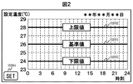
- FIG. 2 shows an example of the interface of the input function 0105.
- the occupant uses this function to set a reference value 0201, an upper limit value 0202, and a lower limit value 0203 of the air conditioning set temperature.
- the reference value 0201 is a set temperature selected by the user when not saving energy.
- the upper limit value 0202 is an allowable upper limit value when the heat demand adjusting device of the energy network in this embodiment controls the air conditioning set temperature.
- the lower limit value 0203 is an allowable lower limit value when the heat demand adjusting device of the energy network in this embodiment controls the air conditioning set temperature.
- Various means can be considered for the occupant to set the reference value 0201, the upper limit value 0202, and the lower limit value 0203.
- a touch panel is assumed, and the reference value 0201, the upper limit value 0202, and the lower limit value 0203 are considered. Each can be moved up and down on the screen.
- the reference value 0201, the upper limit value 0202, and the lower limit value 0203 do not need to be constant values regardless of the time zone, and may be changed to values according to the time zone.
- a “set” button 0204 is provided in the interface of the input function of the present embodiment. When the resident sets the reference value 0201, upper limit value 0202, and lower limit value 0203 and touches the “Set” button 0204, the information on the reference value 0201, upper limit value 0202, and lower limit value 0203 for each time is determined for air conditioning output. Transmitted to function 0116.
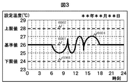
- FIG. 3 shows an example of the interface of the output function 0106.
- the reference value 0301, the upper limit value 0302, and the lower limit value 0303 are the same values as the reference value 0201, the upper limit value 0202, and the lower limit value 0203 set by the occupant using the input function 0105.
- Reference numeral 0304 denotes a set temperature of the air conditioner, which is a value instructed to the air conditioner 0103 by the air conditioning output setting function 0116.
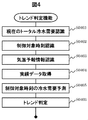
- Fig. 4 is a flowchart of the trend judgment function 0112.
- S0401 is the current recognition of total cold water demand.
- the total cold water demand is obtained by adding the cold water loads sent from each refrigerator 0101.
- S0402 is recognition of the control target time.
- the heat demand adjusting apparatus shown in the present embodiment repeatedly instructs the output of the air conditioner 0103 at regular intervals.
- the time corresponding to the next control cycle with respect to the current time is recognized.
- S0403 is recognition of temperature forecast information.
- temperature information corresponding to the control target time recognized in S0402 is acquired from the weather forecast acquisition function 0110.
- S0404 is acquisition of performance data.
- the acquisition period may be arbitrarily set, such as the past 30 days from the present, or 30 days in the future from the same day one year ago.
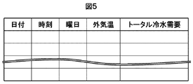
- Fig. 5 shows the data format of the demand performance database.
- information on actual measured values of past total cold water demand is recorded in association with date, time, day of the week, and outside temperature.
- S0405 is a prediction of the chilled water demand at the control target time.
- the size of the total cold water demand at the next control target time is predicted based on the actual data acquired in S0404. Any prediction method may be used.
- a prediction method for example, an MBR (Memory ⁇ ⁇ ⁇ Based Reasoning) method may be used.
- MBR Memory ⁇ ⁇ ⁇ Based Reasoning
- size of the total cold water demand of the next control object time can be estimated by implementation of the MBR method which uses the value of external temperature as a parameter using this selected performance data.
- Equation 0406 is a trend determination. In this process, whether the total chilled water demand is an upward trend or a downward trend based on the difference between the current total chilled water demand recognized in S0401 and the predicted total chilled water demand at the next control target time predicted in S0405. Determine whether the trend is a trend or a trend without change.
- Equation 1 An example of the determination method is shown in Equation 1.
- ⁇ P P1 ⁇ P0 Equation 1
- P0 is the total chilled water demand at the current time (obtained at S0401)
- P1 is the predicted value of the total chilled water demand at the next control target time (obtained at S0405).
- FIG. 6 is a flowchart of the increase / decrease stage determination function 0113.
- S0601 is the recognition of the current number of operating refrigerators. Information on the number of operating refrigerators is owned by this function 0113 in the internal memory, and the recorded information is referred to.
- S0602 is recognition of the trend of cold water demand.
- the chilled water demand trend information is received from the trend determination function 0112.
- S0603 is a conditional branch according to the trend of cold water demand. If the chilled water demand is on an upward trend, the process proceeds to S0604. If the cold water demand is in a downward trend, the process proceeds to S0606. If the chilled water demand is a trend without change, the process proceeds to S0608.
- S0604 is a branch depending on the number of operating refrigerators and the state of the representative room temperature when the cold water demand is on an upward trend.
- the representative room temperature is the room temperature of a specific room when a plurality of rooms 0102 exist. According to the present embodiment, even if there are a plurality of rooms 0102, the room temperature is the same in each of the rooms 0102.
- this process 0604 if the number of operating refrigerators is 0, or the operating number of refrigerators is greater than 0 and the representative room temperature is equal to or higher than the reference temperature 0201 + ⁇ ( ⁇ ⁇ 0), the determination is true, and the process proceeds to S0605. . If the determination is false, the process proceeds to S0610.
- S0605 is a process of adding one refrigerator.
- One chiller with the highest operating efficiency among the stopped chillers is activated by this process.
- S0607 is a step-down process for one refrigerator. This process stops one of the refrigerators with the lowest operating efficiency among the operating refrigerators.
- S0608 is a conditional branch by the number of refrigerators operated and the reference temperature when the total cold water demand is a trend without change. If the number of operating refrigerators is 0 and the representative room temperature is equal to or higher than the reference temperature 0201 + ⁇ , the determination is true, and the process proceeds to S0605. If the determination is false, the process proceeds to S0609.
- the value of ⁇ may be set arbitrarily.
- S0609 if the number of operating refrigerators is one and the representative room temperature is less than the reference temperature 0201 + ⁇ , the determination is true and the process proceeds to S0607. On the other hand, if the determination is false, the process proceeds to S0610. Note that the value of ⁇ may be set arbitrarily.
- S0610 is a notification of the number of operating units. Information on the number of operating refrigerators having received the result of the increase or decrease is transmitted to the load adjustment amount calculation function 0115.
- FIG. 7 shows an example of the data format of the refrigerator characteristic database 0114.
- this database information on efficiency with respect to rated output and load factor is recorded for each refrigerator.
- FIG. 8 is a graph showing an example of the efficiency characteristic with respect to the load factor shown in FIG. Since the operation efficiency differs for each refrigerator, the efficiency varies depending on the refrigerator even at the same load factor as shown in the figure.
- the operating efficiency is higher in the order of the refrigerators A, B, and C, and each refrigerator has the highest efficiency when the load factor is 1.
- the efficiency is improved in the order of the refrigerator A, the refrigerator B, and the refrigerator C at any load factor, but this is for an easy-to-understand example, for example, a load factor of 0.7
- a system may be used in which the refrigerator B is more efficient than the refrigerator A, and the refrigerator C is more efficient than the refrigerators A and B at a load factor of 0.8.
- the efficiency is monotonously improved at any load factor, but this is to give an easy-to-understand example, for example, in the refrigerator A, the efficiency is the best at a load of 0.85, In the refrigerator B, a system having the best efficiency at a load of 0.8 may be used, and in the refrigerator C, a system having the highest efficiency at a load of 0.75 may be used. In addition, what is necessary is just to take the average value of the operating efficiency of each refrigerator as the operation efficiency of the refrigerator total when operating a refrigerator with two or more units.
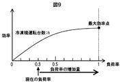
- FIG. 9 is an outline of the processing contents of the load adjustment amount calculation function 0115. This shows the efficiency pattern for the load factor when operating the refrigerator with n units. Similarly to the example of the efficiency characteristic with respect to the load factor shown in FIG. 8, for example, if any one of the refrigerators A, B, and C is smaller than the load 1 and has the best efficiency, FIG. The system with the best efficiency at a load of 0.95.
- FIG. 10 is a flowchart of the load adjustment amount calculation function 0115.
- S1001 is the recognition of the operating refrigerator. That is, it recognizes which refrigerator is in operation.
- the recognizing method of the operating refrigerator is recognized based on the number of operating units received from the increase / decrease stage determination function 0113, that the refrigerator is operating in descending order of operating efficiency.
- S1002 is recognition of refrigerator characteristics.
- the efficiency with respect to the load factor is acquired for the refrigerator recognized as being operated in S1001. Furthermore, the efficiency with respect to the load factor in the total refrigerator is calculated by calculating the average value of the efficiency of the refrigerator in operation.
- S1003 is the current recognition of total cold water demand.
- the current total cold water demand may be summed up with the size of the cold water load sent from each refrigerator 0101.
- S1004 is a load factor calculation.
- the current load factor value is obtained by dividing the total chilled water demand calculated in S1003 by the total value of the rated output of the currently operating refrigerators recognized with reference to the refrigerator characteristic database 0114.
- S1005 is a calculation of the load factor increase amount.
- the increase rate for increasing the load factor value calculated in S1004 to a load factor at which the entire refrigerator can be operated at the highest efficiency is calculated.
- S1006 is a calculation of the load increase amount.
- the total value of the rated output of the refrigerator currently in operation may be added to the increase rate of the load factor obtained in S1005.
- This load increase information is output to the air conditioning output determination function 0116.
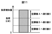
- FIG. 11 is an outline of the processing of the air conditioning output determination function 0116.
- the load increase amount calculated by the load adjustment amount calculation function 0115 is assigned to each air conditioner.
- an image of allocating the magnitude of the load increase to the air conditioners A, B, and C is shown.
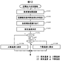
- FIG. 12 is a flowchart of the air conditioning output determination function 0116.
- S1201 is the recognition of the load increase.
- the load increase amount information is received from the load adjustment amount calculation function 0115.
- S1202 is an estimate of the ratio of indoor heat load by air conditioner.
- the heat load referred to here refers to the energy generated by the heat sources (such as people and computers) inside the room and the heat entering from outside the room.
- the ratio of the magnitude of the heat load for each air conditioner is obtained. Any method may be used to obtain the ratio. For example, when there are three air conditioners, the ratio of the heat load when the air conditioner output is kept constant and the room temperature rise during a certain period of time is 1 ° C, 1 ° C, and 2 ° C, respectively. Can be calculated as one-to-one to two.
- S1203 is the allocation of the load increase amount to each air conditioner.
- the load adjustment amount for each air conditioner is assigned according to Equation 2.
- Qn is the load increase amount for air conditioner n
- Q0 is the load increase amount calculated by load adjustment amount calculation function 0115
- Rn is the ratio of the heat load of air conditioner n obtained in S1202
- N is the air conditioner The number of machines.
- S1024 is the determination of the set temperature for each air conditioner.
- the set temperature for actually increasing the load amount to be increased for each air conditioner calculated in S1203 is determined with reference to the information of the set temperature database 0117.
- a set temperature database 0117 is used to determine the set temperature.
- FIG. 13 shows an example of the data format of the set temperature database 0117.
- a change amount of the set temperature for increasing a desired load is recorded for each air conditioner. Note that the data recorded in this database may be customized as appropriate according to the outside air temperature, the prior air conditioning set temperature, or the like.
- a new set temperature is determined by adding the change amount of the set temperature recorded in the set temperature database 0117 to the air conditioning set temperature received from the sensor 0104.
- S1205 is a conditional branch based on a comparison between the set temperature determined in S1204 and the upper limit temperature 0202 set by the occupant. If the set temperature determined in S1204 is the upper limit temperature 0202 or higher, the process proceeds to S1206, and the set temperature is set to the upper limit temperature in S1206. On the other hand, if the set temperature determined in S1204 is lower than the upper limit temperature 0202 in S1205, the process proceeds to S1207.
- S1207 is a conditional branch based on a comparison between the set temperature determined in S1204 and the lower limit temperature 0203 set by the occupant. If the set temperature determined in S1204 is lower than the lower limit temperature 0203, the process proceeds to S1208, and the set temperature is set to the lower limit temperature in S1208. On the other hand, if the set temperature determined in S1204 is higher than the lower limit temperature 0203 in S1207, the air conditioner is instructed to the set temperature determined in S1204.
- FIG. 14 is a diagram showing an energy saving effect according to the present embodiment.
- 1401 is an example of the total cold water demand when the set temperature is a constant value, which is a general air conditioning operation method.
- 1402 is an example of the total cold water demand according to this embodiment.
- the values of 1403, 1404, and 1405 on the vertical axis are the maximum efficiency point in the case of one refrigerator operation, the maximum efficiency point in the case of two unit operation, and the fine efficiency point in the case of three unit operation, respectively. At positions other than 1403, 1404, and 1405 on the vertical axis, the efficiency is not the maximum value.
- the integrated value (namely, area) of the total cold demand throughout the day is almost the same.
- the amount of energy consumed by the heat source system is a value obtained by multiplying the integrated value of the total cooling demand throughout the day by the efficiency of the refrigerator, and therefore, according to this embodiment, compared with the conventional case where the set temperature is constant. Energy saving effect can be increased.
Landscapes
- Engineering & Computer Science (AREA)
- Chemical & Material Sciences (AREA)
- Combustion & Propulsion (AREA)
- Mechanical Engineering (AREA)
- General Engineering & Computer Science (AREA)
- Physics & Mathematics (AREA)
- General Physics & Mathematics (AREA)
- Signal Processing (AREA)
- Automation & Control Theory (AREA)
- General Business, Economics & Management (AREA)
- Business, Economics & Management (AREA)
- Theoretical Computer Science (AREA)
- Mathematical Physics (AREA)
- Fuzzy Systems (AREA)
- Life Sciences & Earth Sciences (AREA)
- Sustainable Development (AREA)
- Software Systems (AREA)
- Power Engineering (AREA)
- Artificial Intelligence (AREA)
- Computer Vision & Pattern Recognition (AREA)
- Health & Medical Sciences (AREA)
- Medical Informatics (AREA)
- Evolutionary Computation (AREA)
- Air Conditioning Control Device (AREA)
Abstract
Description
δP=P1-P0 ・・・式1
ここで、P0は現在時刻におけるトータル冷水需要(S0401で取得したもの)、P1は次回の制御対象時刻にけるトータル冷水需要の予測値(S0405で取得したもの)である。そして、
δP>Xの場合は上昇トレンド、
Y≦δP≦Xの場合は変化なしトレンド、
δP<Yの場合は下降トレンド
と判定する。トレンドの判定結果は増減段判定機能0113へ送られる。
S0610は、運転台数の通知である。増段や減段の結果を受けた冷凍機の運転台数の情報が負荷調整量演算機能0115へ伝達される。
なお、冷凍機を複数台で運転するときの冷凍機トータルの運転効率は、各冷凍機の運転効率の平均値を取ればよい。
ここで、Qnは空調機nに対する負荷増加量、Q0は負荷調整量演算機能0115にて算出した負荷増加量、RnはS1202で求めた空調機nの熱負荷の大きさの割合、Nは空調機の台数である。
0102 部屋
0103 空調機
0104 センサ機能
0105 入力機能
0106 出力機能
0107 第1の送水管
0108 第2の送水管
0109 熱需要調整装置
0110 気象予報取得機能
0111 需要実績データベース
0112 トレンド判定機能
0113 増減段判定機能
0114 冷凍機特性データベース
0115 負荷調整量演算機能
0116 空調出力決定機能
0117 設定温度データベース
0201 設定温度の基準値
0202 設定温度の上限値
0203 設定温度の下限値
0204 セットボタン
0301 設定温度の基準値
0302 設定温度の上限値
0303 設定温度の下限値
0304 空調機の設定温度
1401 設定温度が一定の場合のトータル冷水需要の一例
1402 本実施例におけるトータル冷水需要の一例
1403 冷凍機1台運転の場合の最大効率点
1404 冷凍機2台運転の場合の最大効率点
1405 冷凍機3台運転の場合の最大効率点
Claims (8)
- 複数の熱源機器と、流体路と、前記複数の熱源機器からの熱が前記流体路を介して伝達される複数の空調機を有して、前記複数の熱源は、運転台数通知信号に応じた台数で運転すると共に前記流体路の流体が予め定められた所定値となるように動作し、前記複数の空調機は、指令値に近づくように前記流体路から熱エネルギーを授受するように動作するエネルギーネットワークにおける熱需要を調整する熱需要調整装置であって、
前記複数の熱源機器に対して何れを運転させるかを示す前記運転台数通知信号を生成する台数通知手段と、
前記空調機が授受する熱需要を演算する需要演算手段と、
前記演算された熱需要に応じ前記熱源機器の負荷特性に基づき前記熱源機器の効率が向上するように前記空調機への前記指令値を生成する指令値生成手段とを有することを特徴とするエネルギーネットワークの熱需要調整装置。
- 請求項1に記載のエネルギーネットワークの熱需要調整装置であって、前記複数の熱源の合計負荷が所望の大きさとなるように制御することを特徴とするエネルギーネットワークの熱需要調整装置。
- 請求項1に記載のエネルギーネットワークの熱需要調整装置であって、前記指令値は、前記熱源における負荷率に対する効率に基づいて求められることを特徴とするエネルギーネットワークの熱需要調整装置。
- 請求項3に記載のエネルギーネットワークの熱需要調整装置であって、室内の発熱量と室外からの侵入熱の大きさの少なくとも一方に基づいて前記熱源機器の運転台数が決められることを特徴とするエネルギーネットワークの熱需要調整装置。
- 請求項4に記載のエネルギーネットワークの熱需要調整装置であって、前記指令値は、前記空調機の設定温度であることを特徴とするエネルギーネットワークの熱需要調整装置。
- 請求項1乃至5のいずれかに記載のエネルギーネットワークの熱需要調整装置であって、前記空調機器が設けられている室温の情報に基づき前記熱源を起動或いは停止制御することを特徴とするエネルギーネットワークの熱需要調整装置。
- 請求項1乃至6のいずれかに記載のエネルギーネットワークの熱需要調整装置であって、
前記熱源機器は冷凍機であることを特徴とするエネルギーネットワークの熱需要調整装置。
- 複数の熱源機器と、流体路と、前記複数の熱源からの熱が前記流体路を介して伝達される複数の空調機を有して、前記複数の熱源機器は、運転台数通知信号に応じた台数で運転すると共に前記流体路の流体が予め定められた所定値となるように動作し、前記複数の空調機は、指令値に近づくように前記流体路から熱エネルギーを授受するように動作するエネルギーネットワークにおける熱需要を調整する熱需要調整方法であって、
前記複数の熱源機器に対して何れを運転させるかを示す前記運転台数通知信号を生成し、
前記空調機が授受する熱需要を演算し、
前記演算された熱需要に応じ前記熱源機器の負荷特性に基づき前記熱源機器の効率が向上するように前記空調機への前記指令値を生成するエネルギーネットワークの熱需要調整方法。
Priority Applications (4)
| Application Number | Priority Date | Filing Date | Title |
|---|---|---|---|
| EP14894973.8A EP3159621B1 (en) | 2014-06-20 | 2014-06-20 | Thermal demand adjustment device for energy network and thermal demand adjustment method for energy network |
| PCT/JP2014/066369 WO2015194024A1 (ja) | 2014-06-20 | 2014-06-20 | エネルギーネットワークの熱需要調整装置及びエネルギーネットワークの熱需要調整方法 |
| US15/320,429 US11143426B2 (en) | 2014-06-20 | 2014-06-20 | Thermal demand adjustment device for energy network and thermal demand adjustment method for energy network |
| JP2016528742A JP6258487B2 (ja) | 2014-06-20 | 2014-06-20 | エネルギーネットワークの熱需要調整装置及びエネルギーネットワークの熱需要調整方法 |
Applications Claiming Priority (1)
| Application Number | Priority Date | Filing Date | Title |
|---|---|---|---|
| PCT/JP2014/066369 WO2015194024A1 (ja) | 2014-06-20 | 2014-06-20 | エネルギーネットワークの熱需要調整装置及びエネルギーネットワークの熱需要調整方法 |
Publications (1)
| Publication Number | Publication Date |
|---|---|
| WO2015194024A1 true WO2015194024A1 (ja) | 2015-12-23 |
Family
ID=54935053
Family Applications (1)
| Application Number | Title | Priority Date | Filing Date |
|---|---|---|---|
| PCT/JP2014/066369 Ceased WO2015194024A1 (ja) | 2014-06-20 | 2014-06-20 | エネルギーネットワークの熱需要調整装置及びエネルギーネットワークの熱需要調整方法 |
Country Status (4)
| Country | Link |
|---|---|
| US (1) | US11143426B2 (ja) |
| EP (1) | EP3159621B1 (ja) |
| JP (1) | JP6258487B2 (ja) |
| WO (1) | WO2015194024A1 (ja) |
Cited By (3)
| Publication number | Priority date | Publication date | Assignee | Title |
|---|---|---|---|---|
| JP2018025360A (ja) * | 2016-08-10 | 2018-02-15 | 三菱重工サーマルシステムズ株式会社 | 熱源システム及びその制御方法 |
| CN108800378A (zh) * | 2018-05-30 | 2018-11-13 | 安徽华冶新能源科技有限公司 | 一种基于物联网技术的地源热泵空调系统 |
| WO2025001692A1 (zh) * | 2023-06-30 | 2025-01-02 | 国创移动能源创新中心(江苏)有限公司 | 一种整合能源设备的热管理系统及其工作方法 |
Families Citing this family (4)
| Publication number | Priority date | Publication date | Assignee | Title |
|---|---|---|---|---|
| CN109100947A (zh) * | 2018-09-18 | 2018-12-28 | 顾建国 | 一种智能家居家电多功能服务系统及其控制方法 |
| CN110094847B (zh) * | 2019-05-24 | 2020-08-14 | 珠海格力电器股份有限公司 | 高效控制模块化机组的方法及装置 |
| CN119508965B (zh) * | 2025-01-20 | 2025-04-08 | 南京深度智控科技有限公司 | 一种基于机理模型的蒸发冷空调节能优化控制方法及系统 |
| CN121297305B (zh) * | 2025-09-27 | 2026-03-24 | 中兵占一新能源科技集团有限公司 | 一种双源热泵系统的控制方法 |
Citations (7)
| Publication number | Priority date | Publication date | Assignee | Title |
|---|---|---|---|---|
| JPH04198647A (ja) * | 1990-11-29 | 1992-07-20 | Shimizu Corp | 空調用熱源機器の制御システム |
| JP2005114295A (ja) * | 2003-10-09 | 2005-04-28 | Takasago Thermal Eng Co Ltd | 熱源システム及び制御装置 |
| US7249043B1 (en) * | 2000-03-10 | 2007-07-24 | E.P.M., Inc. | Computer program and method for reducing HVAC demand for energy |
| JP2008045810A (ja) * | 2006-08-15 | 2008-02-28 | Mitsubishi Electric Building Techno Service Co Ltd | 空気調和機の診断装置 |
| US20130167560A1 (en) * | 2010-10-13 | 2013-07-04 | Weldtech Technology (Shanghai) Co., Ltd. | Energy-saving optimized control system and method for refrigeration plant room |
| JP2014035092A (ja) * | 2012-08-07 | 2014-02-24 | Daikin Ind Ltd | 空調システム |
| JP2014092301A (ja) * | 2012-11-01 | 2014-05-19 | Samsung R&D Institute Japan Co Ltd | 空気調和装置及び空気調和装置用プログラム |
Family Cites Families (7)
| Publication number | Priority date | Publication date | Assignee | Title |
|---|---|---|---|---|
| US4463574A (en) * | 1982-03-15 | 1984-08-07 | Honeywell Inc. | Optimized selection of dissimilar chillers |
| US6453993B1 (en) * | 2000-05-17 | 2002-09-24 | Carrier Corporation | Advanced starting control for multiple zone system |
| JP4178786B2 (ja) * | 2001-11-02 | 2008-11-12 | 株式会社大林組 | 空調・熱源設備最適抑制制御システム |
| JP5132334B2 (ja) * | 2008-01-28 | 2013-01-30 | 株式会社東芝 | 空調制御装置およびこれを用いた空調制御システム |
| KR20130120865A (ko) * | 2012-04-26 | 2013-11-05 | 에스케이텔레콤 주식회사 | 빌딩 에너지 관리 시스템에서의 냉동기 대수 제어 장치 및 방법 |
| JP5284528B2 (ja) | 2012-11-05 | 2013-09-11 | 株式会社東芝 | 空調制御装置、空調システム、空調制御方法、空調制御用プログラム |
| JP5994130B2 (ja) * | 2012-11-19 | 2016-09-21 | 公立大学法人大阪市立大学 | 熱エネルギー搬送システム、熱融通システム及び熱エネルギー搬送方法 |
-
2014
- 2014-06-20 EP EP14894973.8A patent/EP3159621B1/en active Active
- 2014-06-20 WO PCT/JP2014/066369 patent/WO2015194024A1/ja not_active Ceased
- 2014-06-20 JP JP2016528742A patent/JP6258487B2/ja not_active Expired - Fee Related
- 2014-06-20 US US15/320,429 patent/US11143426B2/en active Active
Patent Citations (7)
| Publication number | Priority date | Publication date | Assignee | Title |
|---|---|---|---|---|
| JPH04198647A (ja) * | 1990-11-29 | 1992-07-20 | Shimizu Corp | 空調用熱源機器の制御システム |
| US7249043B1 (en) * | 2000-03-10 | 2007-07-24 | E.P.M., Inc. | Computer program and method for reducing HVAC demand for energy |
| JP2005114295A (ja) * | 2003-10-09 | 2005-04-28 | Takasago Thermal Eng Co Ltd | 熱源システム及び制御装置 |
| JP2008045810A (ja) * | 2006-08-15 | 2008-02-28 | Mitsubishi Electric Building Techno Service Co Ltd | 空気調和機の診断装置 |
| US20130167560A1 (en) * | 2010-10-13 | 2013-07-04 | Weldtech Technology (Shanghai) Co., Ltd. | Energy-saving optimized control system and method for refrigeration plant room |
| JP2014035092A (ja) * | 2012-08-07 | 2014-02-24 | Daikin Ind Ltd | 空調システム |
| JP2014092301A (ja) * | 2012-11-01 | 2014-05-19 | Samsung R&D Institute Japan Co Ltd | 空気調和装置及び空気調和装置用プログラム |
Non-Patent Citations (1)
| Title |
|---|
| See also references of EP3159621A4 * |
Cited By (3)
| Publication number | Priority date | Publication date | Assignee | Title |
|---|---|---|---|---|
| JP2018025360A (ja) * | 2016-08-10 | 2018-02-15 | 三菱重工サーマルシステムズ株式会社 | 熱源システム及びその制御方法 |
| CN108800378A (zh) * | 2018-05-30 | 2018-11-13 | 安徽华冶新能源科技有限公司 | 一种基于物联网技术的地源热泵空调系统 |
| WO2025001692A1 (zh) * | 2023-06-30 | 2025-01-02 | 国创移动能源创新中心(江苏)有限公司 | 一种整合能源设备的热管理系统及其工作方法 |
Also Published As
| Publication number | Publication date |
|---|---|
| EP3159621A4 (en) | 2018-02-21 |
| US11143426B2 (en) | 2021-10-12 |
| JP6258487B2 (ja) | 2018-01-10 |
| EP3159621A1 (en) | 2017-04-26 |
| JPWO2015194024A1 (ja) | 2017-04-20 |
| US20170159959A1 (en) | 2017-06-08 |
| EP3159621B1 (en) | 2021-05-05 |
Similar Documents
| Publication | Publication Date | Title |
|---|---|---|
| JP6258487B2 (ja) | エネルギーネットワークの熱需要調整装置及びエネルギーネットワークの熱需要調整方法 | |
| US11662113B2 (en) | Building cooling systems with energy optimization and model predictive control | |
| EP3441690B1 (en) | Central plant control system with time dependent deferred load | |
| US10876754B2 (en) | Dynamic central plant control based on load prediction | |
| CN103403465B (zh) | 蓄电蓄热最佳化装置、最佳化方法及最佳化程序 | |
| CN106062485B (zh) | 用于控制空调设备或空调系统的舒适温度的装置和方法 | |
| EP3194858B1 (en) | Temperature control method and apparatus | |
| KR102747287B1 (ko) | 제어 장치, 공기 조화 장치 및 제어 방법 | |
| JP6422710B2 (ja) | エネルギーネットワークの運転制御装置及び運転制御方法 | |
| US10544956B2 (en) | HVAC system start/stop control | |
| US20210055701A1 (en) | Central plant control system based on load prediction through mass storage model | |
| CN101457968B (zh) | 利用空调系统来控制环境的舒适度的方法 | |
| US20170328595A1 (en) | Environmental control equipment and environmental control system | |
| EP2511618A2 (en) | Air conditioning system and air conditioning method | |
| CN114784811B (zh) | 电力需求响应方法和装置 | |
| CN107300243A (zh) | 空调系统、风档调节方法及计算机可读存储介质 | |
| JP2003074943A (ja) | 空調制御方法およびその装置 | |
| CN106839257A (zh) | 一种控制空调器的方法 | |
| JP2020067207A (ja) | 制御プログラム、制御方法および制御装置 | |
| JP6637323B2 (ja) | 設備管理装置及びプログラム | |
| JP6060014B2 (ja) | エネルギーネットワークの運転制御方法および装置 | |
| CN115638525A (zh) | 一种暖通空调机组运行方法及系统 | |
| JP2008025951A (ja) | 空調設備の運転制御方法および装置 | |
| EP4517203A1 (en) | Building chiller/heat pump system carbon emission reduction by shifting temperature setpoint | |
| KR20180011672A (ko) | 공기조화기 시스템 및 그 방법 |
Legal Events
| Date | Code | Title | Description |
|---|---|---|---|
| 121 | Ep: the epo has been informed by wipo that ep was designated in this application |
Ref document number: 14894973 Country of ref document: EP Kind code of ref document: A1 |
|
| ENP | Entry into the national phase |
Ref document number: 2016528742 Country of ref document: JP Kind code of ref document: A |
|
| REEP | Request for entry into the european phase |
Ref document number: 2014894973 Country of ref document: EP |
|
| WWE | Wipo information: entry into national phase |
Ref document number: 2014894973 Country of ref document: EP |
|
| NENP | Non-entry into the national phase |
Ref country code: DE |
|
| WWE | Wipo information: entry into national phase |
Ref document number: 15320429 Country of ref document: US |