WO2015194087A1 - タイヤ - Google Patents
タイヤ Download PDFInfo
- Publication number
- WO2015194087A1 WO2015194087A1 PCT/JP2015/002325 JP2015002325W WO2015194087A1 WO 2015194087 A1 WO2015194087 A1 WO 2015194087A1 JP 2015002325 W JP2015002325 W JP 2015002325W WO 2015194087 A1 WO2015194087 A1 WO 2015194087A1
- Authority
- WO
- WIPO (PCT)
- Prior art keywords
- pneumatic tire
- adhesive
- tire
- ring member
- tread member
- Prior art date
- Legal status (The legal status is an assumption and is not a legal conclusion. Google has not performed a legal analysis and makes no representation as to the accuracy of the status listed.)
- Ceased
Links
Images

Classifications
-
- B—PERFORMING OPERATIONS; TRANSPORTING
- B60—VEHICLES IN GENERAL
- B60C—VEHICLE TYRES; TYRE INFLATION; TYRE CHANGING; CONNECTING VALVES TO INFLATABLE ELASTIC BODIES IN GENERAL; DEVICES OR ARRANGEMENTS RELATED TO TYRES
- B60C11/00—Tyre tread bands; Tread patterns; Anti-skid inserts
-
- B—PERFORMING OPERATIONS; TRANSPORTING
- B60—VEHICLES IN GENERAL
- B60C—VEHICLE TYRES; TYRE INFLATION; TYRE CHANGING; CONNECTING VALVES TO INFLATABLE ELASTIC BODIES IN GENERAL; DEVICES OR ARRANGEMENTS RELATED TO TYRES
- B60C7/00—Non-inflatable or solid tyres
- B60C7/10—Non-inflatable or solid tyres characterised by means for increasing resiliency
- B60C7/14—Non-inflatable or solid tyres characterised by means for increasing resiliency using springs
-
- B—PERFORMING OPERATIONS; TRANSPORTING
- B60—VEHICLES IN GENERAL
- B60C—VEHICLE TYRES; TYRE INFLATION; TYRE CHANGING; CONNECTING VALVES TO INFLATABLE ELASTIC BODIES IN GENERAL; DEVICES OR ARRANGEMENTS RELATED TO TYRES
- B60C7/00—Non-inflatable or solid tyres
-
- B—PERFORMING OPERATIONS; TRANSPORTING
- B60—VEHICLES IN GENERAL
- B60C—VEHICLE TYRES; TYRE INFLATION; TYRE CHANGING; CONNECTING VALVES TO INFLATABLE ELASTIC BODIES IN GENERAL; DEVICES OR ARRANGEMENTS RELATED TO TYRES
- B60C7/00—Non-inflatable or solid tyres
- B60C7/10—Non-inflatable or solid tyres characterised by means for increasing resiliency
- B60C7/14—Non-inflatable or solid tyres characterised by means for increasing resiliency using springs
- B60C7/146—Non-inflatable or solid tyres characterised by means for increasing resiliency using springs extending substantially radially, e.g. like spokes
-
- B—PERFORMING OPERATIONS; TRANSPORTING
- B60—VEHICLES IN GENERAL
- B60C—VEHICLE TYRES; TYRE INFLATION; TYRE CHANGING; CONNECTING VALVES TO INFLATABLE ELASTIC BODIES IN GENERAL; DEVICES OR ARRANGEMENTS RELATED TO TYRES
- B60C7/00—Non-inflatable or solid tyres
- B60C7/10—Non-inflatable or solid tyres characterised by means for increasing resiliency
- B60C7/14—Non-inflatable or solid tyres characterised by means for increasing resiliency using springs
- B60C7/16—Non-inflatable or solid tyres characterised by means for increasing resiliency using springs of helical or flat coil form
- B60C7/18—Non-inflatable or solid tyres characterised by means for increasing resiliency using springs of helical or flat coil form disposed radially relative to wheel axis
-
- B—PERFORMING OPERATIONS; TRANSPORTING
- B60—VEHICLES IN GENERAL
- B60C—VEHICLE TYRES; TYRE INFLATION; TYRE CHANGING; CONNECTING VALVES TO INFLATABLE ELASTIC BODIES IN GENERAL; DEVICES OR ARRANGEMENTS RELATED TO TYRES
- B60C1/00—Tyres characterised by the chemical composition or the physical arrangement or mixture of the composition
- B60C2001/0091—Compositions of non-inflatable or solid tyres
-
- B—PERFORMING OPERATIONS; TRANSPORTING
- B60—VEHICLES IN GENERAL
- B60C—VEHICLE TYRES; TYRE INFLATION; TYRE CHANGING; CONNECTING VALVES TO INFLATABLE ELASTIC BODIES IN GENERAL; DEVICES OR ARRANGEMENTS RELATED TO TYRES
- B60C7/00—Non-inflatable or solid tyres
- B60C2007/005—Non-inflatable or solid tyres made by casting, e.g. of polyurethane
Definitions
- the present invention relates to a non-pneumatic tire that can be used without being filled with pressurized air.
- a “non-pneumatic tire” (see Patent Document 1), which includes a tread layer provided on the outer side (outer peripheral side) of the belt layer and is capable of integrally forming the support structure with, for example, resin. Yes.
- the belt layer is formed by laminating a rubberized layer of a steel cord or the like, and is joined to the outer peripheral side of a support structure formed of resin.
- the joining state of the tread layer serving as the ground contact surface and the support structure that is attached to the axle and transmits the driving force greatly affects the running function of the tire. It has been known. It is also known that the adhesiveness with a rubber member forming a tread layer (or belt layer) to be bonded to the support structure varies greatly depending on the type of resin member forming the support structure.
- an object of the present invention is a non-pneumatic system that can improve the adhesion between a resin member that forms a structure attached to an axle and a tread member that serves as a ground contact surface while ensuring a necessary traveling function. Is to provide tires.
- a non-pneumatic tire includes an attachment body attached to an axle, an inner cylinder body that is externally attached to the attachment body, and an outer body that surrounds the inner cylinder body from the outside in the tire radial direction.
- a ring member including a cylindrical body, a plurality of connecting members arranged between the inner cylindrical body and the outer cylindrical body along a tire circumferential direction, and connecting the two cylindrical bodies; and an outer cylinder of the ring member
- An adhesive layer containing a cyanoacrylate-based adhesive is provided between the tread member and the outer cylinder of the ring member having an amino group on the surface. According to this configuration, it is possible to improve the adhesiveness between the resin member and the tread member that form the structure attached to the axle while ensuring the required traveling function.
- the synthetic resin material is nylon 12, nylon 66, polybutylene terephthalate (PBT), polyphenylene sulfide (PPS), thermoplastic polyamide elastomer (TPAE), acrylonitrile / butadiene / styrene copolymer Coalescence, polyetheretherketone (PEEK), syndiotactic polystyrene (SPS), polyacetal (POM), polyarylate (PAR), polyethersulfan (PES), polycarbonate (PC), polyamide (PA), polysulfone (PSF) 1) or a mixture of a plurality of types of olefin polymers.
- PBT polybutylene terephthalate
- PPS polyphenylene sulfide
- TPAE thermoplastic polyamide elastomer
- PEEK polyetheretherketone
- SPS syndiotactic polystyrene
- PAM polyacetal
- PAR polyarylate
- PES poly
- the synthetic resin material contains one kind of polyphenylene sulfide (PPS), polycarbonate (PC), polyamide (PA), or a mixture of plural kinds. According to this configuration, it is possible to further improve the impact resistance.
- PPS polyphenylene sulfide
- PC polycarbonate
- PA polyamide
- the surface roughness (Ra) of the adhesion portion between the outer cylinder and the tread member is 0.02-0.5 ⁇ m. According to this configuration, the adhesion performance is further improved by the anchor effect.
- surface roughness (Ra) refers to arithmetic average surface roughness (Ra) (unit: ⁇ m) based on JIS B0601 (1994).
- the maximum height (Ry) of the adhesion part with the said tread member of the said outer cylinder is 3 micrometers or less. According to this configuration, the adhesive adheres more cleanly to the surface of the synthetic resin and vulcanized rubber.
- maximum height (Ry) refers to the maximum height (Ry) (unit: ⁇ m) based on JIS B0601 (1994).
- the adhesive strength of the adhesive layer when the adhesive strength of the adhesive layer is measured in accordance with the tensile shear adhesive strength test method (JISK6850) of adhesive-rigid adherend, 1.0 MPa at a temperature of 25 ° C. The above is preferable. According to this configuration, the adhesive strength can be further maintained. In the non-pneumatic tire of the present invention, when the adhesive strength of the adhesive layer is measured according to the tensile shear adhesive strength test method (JISK6850) of the adhesive-rigid adherend, it is 0.3 MPa at a temperature of 80 ° C. The above is preferable. According to this structure, the adhesive strength at the time of tire running high temperature can be maintained more.
- JISK6850 tensile shear adhesive strength test method
- a non-pneumatic tire capable of improving the adhesion between a resin member and a tread member that form a structure attached to an axle while ensuring a necessary traveling function. it can.
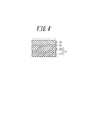
- FIG. 2 is a partial explanatory view showing an enlargement of an adhesive layer provided between the ring member and the tread member of FIG. 1.
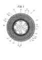
- FIG. 1 is an explanatory view seen from the side of a tire, schematically showing the configuration of a non-pneumatic tire according to an embodiment of the present invention.
- FIG. 2 is an explanatory view showing a part of FIG. 1 in an enlarged manner.
- the non-pneumatic tire 10 of this embodiment includes an attachment body 11 attached to an axle (not shown), an inner cylinder body 12 and an inner cylinder body 12 that are externally mounted on the attachment body 11.
- the ring member 14 provided with the outer cylinder 13 that surrounds the outer side of the tire in the radial direction of the tire and a plurality of both cylinders 12 and 13 disposed between the inner cylinder 12 and the outer cylinder 13 along the tire circumferential direction. It has the connection member 15 which connects each other, and the tread member 16 which consists of vulcanized rubber which covers the outer periphery of the ring member 14 integrally.
- the attachment body 11, the inner cylinder body 12, the outer cylinder body 13, and the tread member 16 are arranged coaxially with the common shaft and in the center in the tire width direction so as to coincide with each other.
- the axis is the axis O
- the direction orthogonal to the axis O is the tire radial direction
- the direction around the axis O is the tire circumferential direction.
- the attachment body 11 connects the mounting cylinder portion 17 to which the front end portion of the axle is mounted, the outer ring portion 18 surrounding the mounting cylinder portion 17 from the outer side in the tire radial direction, and the mounting cylinder portion 17 and the outer ring portion 18. And a plurality of ribs 19 (see FIGS. 1 and 2).
- the mounting cylinder part 17, the outer ring part 18, and the rib 19 are integrally formed of a metal material such as an aluminum alloy.
- the mounting cylinder part 17 and the outer ring part 18 are each formed in a cylindrical shape and arranged coaxially with the axis O.
- the plurality of ribs 19 are arranged at equal intervals in the circumferential direction.
- the connecting member 15 includes a first elastic connecting plate 21 and a second elastic connecting plate 22 that connect the inner cylinder 12 and the outer cylinder 13 in the ring member 14 to each other.
- a plurality of first elastic coupling plates 21 are arranged along the tire circumferential direction at one tire width direction position, and the second elastic coupling plates 22 are arranged in the other tire width direction different from the one tire width direction position.
- a plurality of tires are arranged at positions along the tire circumferential direction. For example, 60 first elastic coupling plates 21 and second elastic coupling plates 22 are provided.
- the plurality of first elastic connecting plates 21 are arranged along the tire circumferential direction at the same position in the tire width direction, and the second elastic connecting plates 22 are the same apart from the first elastic connecting plate 21 in the tire width direction.
- a plurality of tires are arranged at positions in the tire width direction along the tire circumferential direction.
- the plurality of connecting members 15 are individually disposed at positions that are axially symmetric with respect to the axis O between the inner cylinder 12 and the outer cylinder 13 in the ring member 14. All the connecting members 15 have the same shape and size. Furthermore, the width of the connecting member 15 is smaller than the width of the outer cylinder 13 in the tire width direction.
- the first elastic coupling plates 21 adjacent in the tire circumferential direction are not in contact with each other, and the second elastic coupling plates 22 adjacent in the tire circumferential direction are also in non-contact with each other. Further, the first elastic connecting plate 21 and the second elastic connecting plate 22 adjacent in the tire width direction are also not in contact with each other.
- the first elastic connecting plate 21 and the second elastic connecting plate 22 have the same width. The thicknesses of the first elastic connecting plate 21 and the second elastic connecting plate 22 are also equal to each other.
- one end 21 a connected to the outer cylinder 13 is located on one side in the tire circumferential direction from the other end 21 b connected to the inner cylinder 12, and Of the two elastic connecting plates 22, one end 22 a connected to the outer cylinder 13 is located on the other side in the tire circumferential direction with respect to the other end 22 b connected to the inner cylinder 12.
- each end part 21a, 22a of the 1st elastic connection board 21 and the 2nd elastic connection board 22 makes the position in a tire width direction mutually differ in the internal peripheral surface of the outer cylinder 13, and is the same in a tire peripheral direction. It is connected to the position.
- each of the first elastic connecting plate 21 and the second elastic connecting plate 22 intermediate portions 21c and 22c positioned between the one end portions 21a and 22a and the other end portions 21b and 22b are arranged in the tire circumferential direction.
- a plurality of curved portions 21d to 21f and 22d to 22f that are curved are formed along the direction in which the connecting plates 21 and 22 extend in a tire side view of the tire 10 viewed from the tire width direction.
- the bending directions of the bending portions 21d to 21f and 22d to 22f adjacent to each other in the extending direction among the plurality of bending portions 21d to 21f and 22d to 22f are opposite to each other. It has become.
- the plurality of curved portions 21d to 21f formed on the first elastic connecting plate 21 are a first curved portion 21d curved so as to project toward the other side in the tire circumferential direction, a first curved portion 21d, and one end portion. Between the second curved portion 21e, which is located between the first curved portion 21d and the other end portion 21b, and between the first curved portion 21d and the other end portion 21b. And a third curved portion 21f that is curved so as to project toward one side in the tire circumferential direction.
- the plurality of curved portions 22d to 22f formed on the second elastic connecting plate 22 are a first curved portion 22d curved so as to project toward one side in the tire circumferential direction, a first curved portion 22d, and one end portion. 22a, and located between the second curved portion 22e, which is curved so as to protrude toward the other side in the tire circumferential direction, and between the first curved portion 22d and the other end 22b, and A third curved portion 22f that is curved so as to project toward the other side in the tire circumferential direction.
- the first bending portions 21d and 22d have a larger radius of curvature in a tire side view than the second bending portions 21e and 22e and the third bending portions 21f and 22f.
- the first curved portions 21d and 22d are arranged at the center in the extending direction of the first elastic connecting plate 21 and the second elastic connecting plate 22.
- both elastic connecting plates 21 and 22 are equal to each other.
- the other end portions 21 b and 22 b of both elastic connecting plates 21 and 22 are connected to the one end portions 21 a and 22 a and the tire radial direction on the outer peripheral surface of the inner cylindrical body 12 in the tire side view.
- first bending portions 21d and 22d, the second bending portions 21e and 22e, and the third bending portions 21f and 22f of the first elastic connecting plate 21 and the second elastic connecting plate 22 are mutually in the tire circumferential direction.
- the opposite direction is the same and the size is the same.
- each connecting member 15 seen from the side of the tire is the tire radial direction as shown in a pair of first elastic connecting plate 21 and second elastic connecting plate 22 drawn with emphasis by solid lines in FIG. And symmetric with respect to an imaginary line L that passes through the one end portions 21a and 22a of the connecting plates 21 and 22.
- the one end side portion extending from the central portion in the extending direction to the one end portions 21a and 22a has a thickness larger than the other end side portion extending from the central portion to the other end portions 21b and 22b. It is getting bigger.
- the ring member 14 is divided into a one-side split ring member located on one side in the tire width direction and a second-side split ring member located on the other side in the tire width direction, for example, at the center in the tire width direction. It may be.
- the one-side split ring member may be integrally formed with the first elastic connecting plate 21 and the other-side split ring member may be integrally formed with the second elastic connecting plate 22, respectively.
- the elastic connecting plate 21, the other-side split ring member, and the second elastic connecting plate 22 may be integrally formed by injection molding.
- the ring member 14 is fixed to the mounting body 11 in a state where the inner cylindrical body 12 is externally fitted to the mounting body 11.
- the ring member 14 including the inner cylinder 12 and the outer cylinder 13 and the plurality of connecting members 15 are all integrally formed of a synthetic resin material, and the tread member 16 and the outer ring member 14 An adhesive layer 25 containing a cyanoacrylate adhesive is provided between the cylindrical body 13.
- the synthetic resin a flexural modulus of 1.5 GPa to 5 GPa is preferable.
- the synthetic resin material for example, nylon 12, nylon 66, polybutylene terephthalate (PBT), polyphenylene sulfide (PPS), thermoplastic polyamide-based elastomer (TPAE) , Acrylonitrile-butadiene-styrene copolymer (ABS), polyetheretherketone (PEEK), syndiotactic polystyrene (SPS), polyacetal (POM), polyarylate (PAR), polyethersulfane (PES), polycarbonate ( PC), polyamide (PA), a polymer or copolymer of polysulfone (PSF), and a mixture of one kind or plural kinds of olefin polymers.
- any one of polyphenylene sulfide (PPS), polycarbonate (PC), and polyamide (PA), or a mixture of a plurality of types is
- the synthetic resin material may be a mixture containing one or more kinds of resin materials as described above, for example, and one or more kinds of elastomers other than the above, and further, for example, an anti-aging agent, a plasticizer, and a filler. Or an additive such as a pigment.
- the tread member 16 is formed in a cylindrical shape and integrally covers the outer peripheral surface side of the outer cylindrical body 13 of the ring member 14 over the entire area.
- the tread member 16 is formed of a vulcanized rubber obtained by vulcanizing a rubber composition containing, for example, natural rubber from the viewpoint of wear resistance and the like.
- connection member 15 which connects the inner cylinder body 12 and the outer cylinder body 13 is shown.
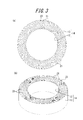
- 3A and 3B show an inner cylinder and an outer cylinder connected by a connecting member according to another example, in which FIG. 3A is a front view and FIG. 3B is a perspective view.
- the connecting member 23 is configured by only the first elastic connecting plate 21, unlike the connecting member 15 configured by the first elastic connecting plate 21 and the second elastic connecting plate 22.
- a plurality of first elastic connecting plates 21 constituting the connecting member 23 are arranged between the inner cylindrical body 12 and the outer cylindrical body 13 along the tire circumferential direction, and connect the cylindrical bodies 12 and 13 to each other.
- Other configurations and operations are the same as those of the connecting member 15.
- FIG. 4 is an enlarged partial explanatory view showing the adhesive layer 25 provided between the ring member 14 and the tread member 16 of FIG.
- the outer cylindrical body 13 of the ring member 14 more specifically, at least the outer peripheral surface of the outer cylindrical body 13 of the ring member 14 on the tread member 16 side is pretreated with an amine compound.
- the adhesive layer 25 is provided between the outer cylinder 13 and the tread member 16 of the ring member 14 pretreated as described above, and joins the outer cylinder 13 and the tread member 16. And contains a cyanoacrylate adhesive.
- the adhesive layer 25 containing a cyanoacrylate adhesive and an amine compound between the outer cylinder 13 of the ring member 14 and the tread member 16 pretreated with the amine compound.
- the ring member 14 integrally formed with the plurality of connecting members 15 by the synthetic resin material and the tread member 16 formed of vulcanized rubber can be reliably joined.
- the cyanoacrylate adhesive used here include ThreeBond (registered trademark) 1757 of ThreeBond Co., Ltd. and Aron Alpha (registered trademark) 221 of Toagosei Co., Ltd.
- the amine compound include polyamide and tetra There is methylhexanediamine.
- the adhesiveness can be improved and improved by interposing the adhesive layer 25 containing a cyanoacrylate adhesive between the ring member 14 and the tread member 16.
- the surface treatment of the synthetic resin material described above is performed with an amine compound having high heat resistance, so that the adhesion strength at the tire running temperature of the adhesion portion is further increased. Can be maintained. That is, the pretreatment can further improve the adhesion of the cyanoacrylate adhesive to the tread material.
- tetramethylhexanediamine as a treating agent is dissolved in n-hexane to give a solution of about 2%, and then applied to the part to be bonded with a brush. The solvent is removed by drying. Thereafter, a cyanoacrylate adhesive is poured between the tread material to be bonded and the adhesive is cured. Although it depends on the environmental humidity and temperature, a few minutes are sufficient for curing.
- the adhesive strength in the adhesive layer 25 is preferably 1.0 MPa or more at a temperature of 25 ° C. when measured in accordance with the tensile shear adhesive strength test method (JIS K6850) of an adhesive-rigid adherend. Thereby, sufficient adhesive strength can be ensured at a temperature of 25 ° C., and the adhesive strength can be further maintained.
- the adhesive strength in the adhesive layer 25 is preferably 0.3 MPa or more at a temperature of 80 ° C. when measured according to the tensile shear adhesive strength test method (JISK6850) of adhesive-rigid adherend. It is more preferable if it is 6 MPa or more. Thereby, sufficient adhesive strength can be ensured at a temperature of 80 ° C., that is, when the tire is running hot, and the adhesive strength can be further maintained.
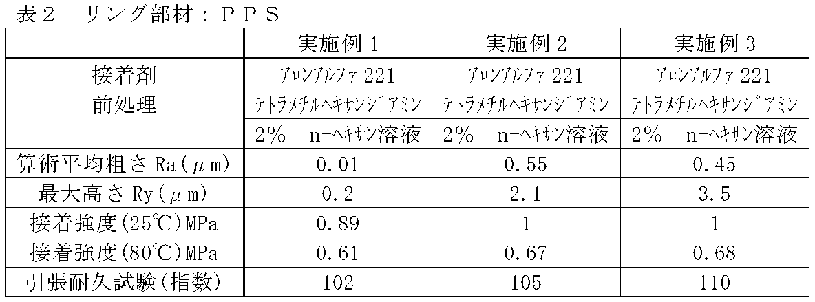
- the arithmetic average roughness (Ra) of the outer cylinder 13 on the tread member 16 side is preferably 0.02 ⁇ m or more. 0.04 ⁇ m or more is more preferable, 0.5 ⁇ m or less is preferable, and 0.45 ⁇ m or less is more preferable.
- the maximum height (Ry) is preferably 3 ⁇ m or less, and more preferably 2.3 ⁇ m or less.
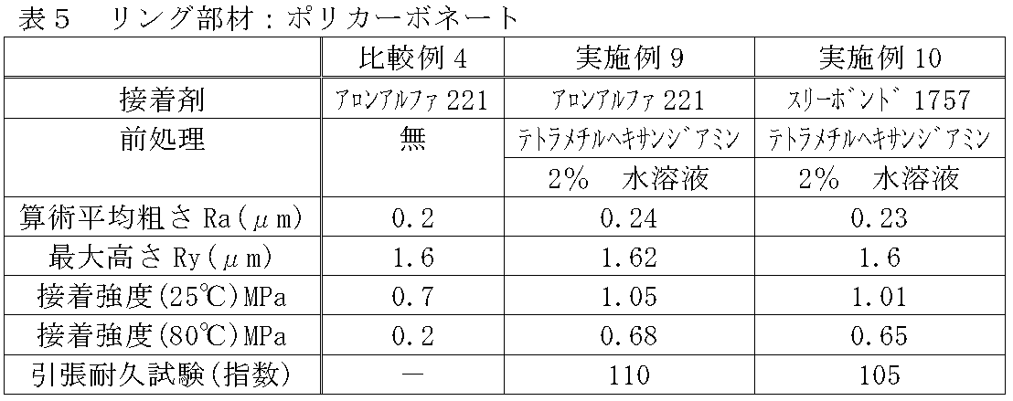
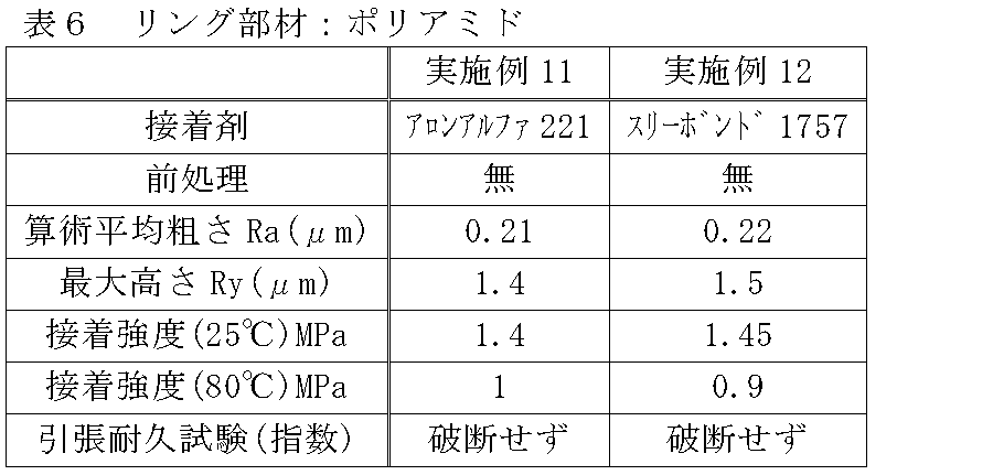
- a plurality of types of non-pneumatic tires according to the present invention were prototyped as examples (Examples 1 to 12), and compared with the non-pneumatic tires of comparative examples (Comparative Examples 1 to 4).
- the non-pneumatic tires of the examples and comparative examples all have a tire size of 155 / 65R13, and the structures thereof are those shown in FIGS.
- Table 1 shows the adhesive contained in the adhesive layer, the amine compound used for the pretreatment of the outer cylindrical body of the ring member, the arithmetic average roughness and maximum height of the outer surface of the outer cylindrical body, and the adhesive strength of the adhesive layer. To Table 3 below. These prototype tires were evaluated by performing a tensile durability test under the following test conditions.
- Dumbbells (JIS K6251 dumbbell shape No. 1) were prepared by injection molding various resin materials. The obtained dumbbell was cut in half in the middle in the length direction and used for the adhesion test. Using two cut dumbbells, vulcanized rubber was sandwiched between them, and the surface of the dumbbells was subjected to an adhesive treatment to measure the adhesive force. As pre-bonding treatment, the pretreatment liquid was applied with a brush or the like, and then the solvent was removed by drying. Thereafter, the adhesive was applied with a brush or the like, sandwiched with vulcanized rubber, and held and cured so as not to slip with a clip or the like. The curing time was the recommended condition for the adhesive used.
- the adhesion area was 10 mm ⁇ 10 mm, and the rubber thickness was 2 mm.
- the dumbbell part of the adhesive sample was sandwiched between chucks and pulled in the opposite direction at a tensile speed of 10 mm / min, and the force at break was measured. The obtained force was divided by the adhesion area to obtain the adhesive strength.
- the test environment temperature was two points of 25 ° C and 80 ° C.
- Adhesion durability test An adhesion durability test was performed on a sample having an adhesive strength at 80 ° C. of 0.2 MPa or more as a result of the above. Using the dynamic fatigue tester (servo pulser: manufactured by Shimadzu Corporation), the sample prepared by the above method is subjected to an adhesion durability test (tensile durability test) at a force of 60 ° C., frequency 10 Hz, ⁇ 5 kgf, The number of cycles until the sample broke was measured. Regarding the index of the experimental data, the index was converted to 100 at 30,000 times. The maximum number of cycles was 100,000.
Landscapes
- Engineering & Computer Science (AREA)
- Mechanical Engineering (AREA)
- Tires In General (AREA)
Abstract
Description
このため、近年では、内部に加圧空気を充填する必要の無いタイヤとして、例えば、車両からの荷重を支持する支持構造体、支持構造体の外周側に設けられるベルト層(設けなくても良い)、ベルト層の外側(外周側)に設けられたトレッド層などを備え、支持構造体を、例えば樹脂により一体成形することが可能な「非空気圧タイヤ」(特許文献1参照)が提案されている。
そこで、この発明の目的は、必要とする走行機能を確保しつつ、車軸に取り付けられる構造体を形成する樹脂部材と接地面となるトレッド部材との接着性の向上を図ることができる非空気入りタイヤを提供することである。
この発明の非空気入りタイヤでは、前記外筒体の前記トレッド部材との接着部分の表面粗さ(Ra)が0.02-0.5μmであることが好ましい。この構成によれば、アンカー効果によってより接着性能が向上する。
この発明の非空気入りタイヤでは、前記外筒体の前記トレッド部材との接着部分の最大高さ(Ry)が3μm以下であることが好ましい。この構成によれば、接着剤が合成樹脂及び加硫ゴムの表面によりきれいに付着する。
なお、本発明において「最大高さ(Ry)」とは、JIS B0601(1994)に基づく最大高さ(Ry)(単位:μm)を指す。
この発明の非空気入りタイヤでは、前記接着層の接着強度が、接着剤-剛性被着材の引張せん断接着強さ試験方法(JISK6850)に準じて測定された場合、温度80℃では0.3MPa以上であることが好ましい。この構成によれば、タイヤ走行高温時の接着強度をより維持することができる。
図1は、この発明の一実施の形態に係る非空気入りタイヤの構成を模式的に示す、タイヤ側面から見た説明図である。図2は、図1の一部を拡大して示す説明図である。なお、図2では、理解し易いように、後述する複数の第1弾性連結板21及び複数の第2弾性連結板22のうち、それぞれ一つの第1弾性連結板21及び第2弾性連結板22のみを、実線で強調して描いている。
ここで、取付け体11、内筒体12、外筒体13、及びトレッド部材16は、それぞれ共通軸と同軸に、また、タイヤ幅方向の中央部を互いに一致させて配置されており、この共通軸を軸線O、軸線Oに直交する方向をタイヤ径方向、軸線O回りに周回する方向をタイヤ周方向という。
装着筒部17、外リング部18、及びリブ19は、例えばアルミニウム合金等の金属材料で一体に形成されている。装着筒部17及び外リング部18はそれぞれ、円筒状に形成され軸線Oと同軸に配設されている。複数のリブ19は、周方向に同等の間隔をあけて配置されている。
なお、複数の連結部材15は、リング部材14における内筒体12と外筒体13との間において、軸線Oを基準に軸対称となる位置に各別に配置されている。また、全ての連結部材15は互いに同形同大となっている。さらに、連結部材15の幅は外筒体13のタイヤ幅方向幅より小さくなっている。
なお、第1弾性連結板21及び第2弾性連結板22それぞれの幅は互いに同等になっている。また、第1弾性連結板21及び第2弾性連結板22それぞれの厚さも互いに同等になっている。
また、第1弾性連結板21及び第2弾性連結板22の各一端部21a、22aは、外筒体13の内周面において、タイヤ幅方向の位置を互いに異ならせて、タイヤ周方向における同一の位置に連結されている。
図示の例では、第1湾曲部21d、22dは、第2湾曲部21e、22e及び第3湾曲部21f、22fよりも、タイヤ側面視の曲率半径が大きくなっている。なお、第1湾曲部21d、22dは、第1弾性連結板21及び第2弾性連結板22の延びる方向における中央部に配置されている。
また、両弾性連結板21,22それぞれにおいて、前述した延びる方向の中央部から一端部21a,22aにわたる一端側部分は、中央部から他端部21b,22bにわたる他端側部分よりも厚さが大きくなっている。これにより、連結部材15の重量の増大を抑えたり、連結部材15の柔軟性を確保したりしながら、第1、第2弾性連結板21,22において大きな負荷がかかり易い一端側部分の強度を高めることができる。なお、これらの一端側部分と他端側部分とは段差なく滑らかに連なっている。
リング部材14は、内筒体12が取付け体11に外嵌された状態で、取付け体11に固定されている。
このなかで、特に、ポリフェニレンサルファイド(PPS)、ポリカーボネート(PC)、ポリアミド(PA)の何れか一種類、或いは複数種類の混合物が望ましい。それは、耐衝撃性が良好だからである。
本実施形態の非空気入りタイヤ10では、トレッド部材16は円筒状に形成され、リング部材14の外筒体13の外周面側を全域にわたって一体に覆っている。トレッド部材16は、耐摩耗性等観点から、例えば天然ゴム等を含むゴム組成物が加硫された加硫ゴムで形成されている。
図3は、他の例による連結部材により連結された内筒体と外筒体を示し、(a)は正面図、(b)は斜視図である。図3に示すように、連結部材23は、第1弾性連結板21及び第2弾性連結板22で構成されている連結部材15とは異なり、第1弾性連結板21のみで構成されている。連結部材23を構成する第1弾性連結板21は、内筒体12と外筒体13の間にタイヤ周方向に沿って複数配置され、両筒体12,13同士を連結している。その他の構成及び作用は、連結部材15と同様である。
ここで用いられる、シアノアクリレート系接着剤としては、例えば、株式会社スリーボンドのスリーボンド(登録商標)1757、東亞合成株式会社のアロンアルファ(登録商標)221があり、アミン化合物としては、例えば、ポリアミド、テトラメチルヘキサンジアミンがある。
リング部材14とトレッド部材16とを接着する場合、具体的には、以下に示す方法で行う。
特に、合成樹脂材料としてポリフェニレンサルファイド(PPS)を用いた場合、特に、困難であった、ポリフェニレンサルファイド(PPS)と加硫ゴムからなるトレッド材料との接着性を、アミノ基を有する化合物とシアノアクリレート系接着剤を含む接着層25の介在により大きく改善して向上させることができ、タイヤの必要とする走行機能を十分確保しつつ、リング部材14とトレッド部材16との接合を特に確実に行うことができる。
この接着層25における接着強度は、接着剤-剛性被着材の引張せん断接着強さ試験方法(JISK6850)に準じて測定された場合、温度80℃では0.3MPa以上であるのが好ましく、0.6MPa以上であれば、より好ましい。これにより、温度80℃、即ち、タイヤ走行高温時において十分な接着強度を確保し、且つ、その接着強度をより維持することができる。
また、外筒体13のトレッド部材16との接着部分、即ち、外筒体13のトレッド部材16側の外周面の算術平均粗さ(Ra)は、0.02μm以上であることが好ましく、0.04μm以上であればより好ましく、また、0.5μm以下であることが好ましく、0.45μm以下であればより好ましい。一方、最大高さ(Ry)は、3μm以下であることが好ましく、2.3μm以下であれは更に好ましい。
接着層に含まれる接着剤、リング部材の外筒体の前処理に用いたアミン系化合物、外筒体の外表面の算術平均粗さと最大高さ、及び接着層の接着強度は、それぞれ表1から表3に示す通りであった。
これらの試作タイヤについて、以下の試験条件の下で引張り耐久試験を行い評価した。
:各種樹脂材料を射出成形により、ダンベル(JIS K6251 ダンベル状1号)を作成した。得られたダンベルを長さ方向に真中で半分にカットし、接着試験に用いた。カットしたダンベル2本を用い、間に加硫ゴムを挟み、ダンベル表面を接着処理して接着力を測定した。接着前処理としては、前処理液を刷毛などで塗布後、溶剤を乾燥除去した。その後、接着剤を刷毛などで塗布し、加硫ゴムを挟み、クリップ等でずれないように保持、硬化させた。硬化時間は使用する接着剤推奨の条件とした。接着面積は10mm×10mm、ゴムの厚さは2mmであった。
接着サンプルのダンベル部をチャックで挟み、引張速度10mm/minで反対方向に引っ張り、破断時の力を測定した。得られた力を接着面積で除し、接着強度とした。試験環境温度は、25℃、80℃の2点であった。
:上記の結果の80℃での接着強度が0.2MPa以上のサンプルについて、接着耐久試験を行った。上記の方法で作成したサンプルを、動的疲労試験機(サーボパルサー:島津製作所製)を用い、60℃、周波数10Hz、±5kgfの力で、接着耐久性の試験(引張耐久試験)を行い、サンプルが破壊するまでのサイクル数を測定した。実験データの指数に関しては、3万回のときに100として指数を換算した。最大サイクル数は、10万回とした。


この発明によれば、必要とする走行機能を確保しつつ、車軸に取り付けられる構造体を形成する樹脂部材とトレッド部材との接着性の向上を図ることができる非空気入りタイヤ提供することができる。
Claims (7)
- 車軸に取り付けられる取付け体と、該取付け体に外装される内筒体及び該内筒体をタイヤ径方向の外側から囲繞する外筒体を備えたリング部材と、前記内筒体と前記外筒体の間にタイヤ周方向に沿って複数配置された、前記両筒体同士を連結する連結部材と、前記リング部材の外筒体のタイヤ径方向外側に設けられた加硫ゴムからなるトレッド部材とを有し、前記外筒体の少なくとも一部及び複数の前記連結部材を合成樹脂材料により一体に形成した非空気入りタイヤであって、
前記トレッド部材と表面にアミノ基を有する前記リング部材の外筒体との間に、シアノアクリレート系接着剤を含む接着層を設けたことを特徴とする、非空気入りタイヤ。 - 前記合成樹脂材料が、ナイロン12、ナイロン66、ポリブチレンテレフタレート(PBT)、ポリフェニレンサルファイド(PPS)、熱可塑性ポリアミド系エラストマー(TPAE)、アクリロニトリル・ブタジエン・スチレン共重合体、ポリエーテルエーテルケトン(PEEK)、シンジオタクチックポリスチレン(SPS)、ポリアセタール(POM)、ポリアリレート(PAR)、ポリエーテルサルファン(PES)、ポリカーボネート(PC)、ポリアミド(PA)、ポリサルフォン(PSF)の重合体又は共重合体、及びオレフィン系重合体の内の一種類、或いは複数種類の混合物を含むことを特徴とする、請求項1に記載の非空気入りタイヤ。
- 前記合成樹脂材料が、ポリフェニレンサルファイド(PPS)、ポリカーボネート(PC)、ポリアミド(PA)の何れか一種類、或いは複数種類の混合物を含むことを特徴とする、請求項1に記載の非空気入りタイヤ。
- 前記外筒体の前記トレッド部材との接着部分の表面粗さ(Ra)が0.02-0.5μmであることを特徴とする、請求項1から3のいずれか一項に記載の非空気入りタイヤ。
- 前記外筒体の前記トレッド部材との接着部分の最大高さ(Ry)が3μm以下であることを特徴とする、請求項1から4のいずれか一項に記載の非空気入りタイヤ。
- 前記接着層の接着強度が、接着剤-剛性被着材の引張せん断接着強さ試験方法(JISK6850)に準じて測定された場合、温度25℃では1.0MPa以上であることを特徴とする、請求項1から5のいずれか一項に記載の非空気入りタイヤ。
- 前記接着層の接着強度が、接着剤-剛性被着材の引張せん断接着強さ試験方法(JISK6850)に準じて測定された場合、温度80℃では0.3MPa以上であることを特徴とする、請求項1から5のいずれか一項に記載の非空気入りタイヤ。
Priority Applications (4)
| Application Number | Priority Date | Filing Date | Title |
|---|---|---|---|
| EP15809122.3A EP3156257B1 (en) | 2014-06-16 | 2015-05-07 | Tire |
| US15/318,724 US20170120681A1 (en) | 2014-06-16 | 2015-05-07 | Tire |
| CN201580032272.2A CN106660395B (zh) | 2014-06-16 | 2015-05-07 | 轮胎 |
| JP2016528989A JP6492076B2 (ja) | 2014-06-16 | 2015-05-07 | タイヤ |
Applications Claiming Priority (2)
| Application Number | Priority Date | Filing Date | Title |
|---|---|---|---|
| JP2014123698 | 2014-06-16 | ||
| JP2014-123698 | 2014-06-16 |
Publications (1)
| Publication Number | Publication Date |
|---|---|
| WO2015194087A1 true WO2015194087A1 (ja) | 2015-12-23 |
Family
ID=54935104
Family Applications (1)
| Application Number | Title | Priority Date | Filing Date |
|---|---|---|---|
| PCT/JP2015/002325 Ceased WO2015194087A1 (ja) | 2014-06-16 | 2015-05-07 | タイヤ |
Country Status (5)
| Country | Link |
|---|---|
| US (1) | US20170120681A1 (ja) |
| EP (1) | EP3156257B1 (ja) |
| JP (1) | JP6492076B2 (ja) |
| CN (1) | CN106660395B (ja) |
| WO (1) | WO2015194087A1 (ja) |
Cited By (12)
| Publication number | Priority date | Publication date | Assignee | Title |
|---|---|---|---|---|
| WO2016148295A1 (ja) * | 2015-03-18 | 2016-09-22 | 株式会社ブリヂストン | 非空気入りタイヤ |
| JP2018002142A (ja) * | 2016-06-28 | 2018-01-11 | ザ・グッドイヤー・タイヤ・アンド・ラバー・カンパニー | 非空気入りタイヤ |
| JP2018058541A (ja) * | 2016-10-07 | 2018-04-12 | 東洋ゴム工業株式会社 | 非空気圧タイヤ及びその製造方法 |
| WO2018211734A1 (ja) * | 2017-05-18 | 2018-11-22 | 株式会社ブリヂストン | タイヤ |
| US10166732B2 (en) | 2013-06-15 | 2019-01-01 | Camso Inc. | Annular ring and non-pneumatic tire |
| CN111344161A (zh) * | 2017-11-10 | 2020-06-26 | 株式会社普利司通 | 非充气轮胎 |
| US10953696B2 (en) | 2015-02-04 | 2021-03-23 | Camso Inc | Non-pneumatic tire and other annular devices |
| US11179969B2 (en) | 2017-06-15 | 2021-11-23 | Camso Inc. | Wheel comprising a non-pneumatic tire |
| JP2022516536A (ja) * | 2019-01-04 | 2022-02-28 | ブリヂストン アメリカズ タイヤ オペレーションズ、 エルエルシー | シム層を有するタイヤトレッドバンド |
| JP2022517547A (ja) * | 2019-01-04 | 2022-03-09 | ブリヂストン アメリカズ タイヤ オペレーションズ、 エルエルシー | バンド層を有するタイヤトレッド |
| JP2023067438A (ja) * | 2021-11-01 | 2023-05-16 | Toyo Tire株式会社 | 非空気圧タイヤの製造方法 |
| US11999419B2 (en) | 2015-12-16 | 2024-06-04 | Camso Inc. | Track system for traction of a vehicle |
Families Citing this family (5)
| Publication number | Priority date | Publication date | Assignee | Title |
|---|---|---|---|---|
| EP3623172A4 (en) | 2017-05-11 | 2020-12-02 | Bridgestone Corporation | TIRE |
| CN107584972A (zh) * | 2017-10-20 | 2018-01-16 | 中山市奔点五金机械有限公司 | 一种轮胎结构及脚轮 |
| CN108482017A (zh) * | 2018-03-05 | 2018-09-04 | 青岛科技大学 | 一种新型弹性体-塑料复合型免充气轮胎 |
| JP7552140B2 (ja) * | 2020-08-19 | 2024-09-18 | 住友ゴム工業株式会社 | エアレスタイヤ |
| JP7436871B2 (ja) * | 2021-08-31 | 2024-02-22 | 横浜ゴム株式会社 | 積層体、積層体の製造方法、及び、タイヤ |
Citations (4)
| Publication number | Priority date | Publication date | Assignee | Title |
|---|---|---|---|---|
| JPS5777202A (en) * | 1980-10-30 | 1982-05-14 | Ohtsu Tire & Rubber Co Ltd | Tire |
| JPH02310102A (ja) * | 1989-05-22 | 1990-12-25 | Uniroyal Goodrich Tire Co:The | 台形断面を有する非空気充填タイヤ |
| JP2005161959A (ja) * | 2003-12-02 | 2005-06-23 | Maeda Sheru Service:Kk | 雪道用再生ソリッドタイヤ及びその製造方法 |
| JP2011219009A (ja) * | 2010-04-12 | 2011-11-04 | Toyo Tire & Rubber Co Ltd | 非空気圧タイヤ及びその製造方法 |
Family Cites Families (6)
| Publication number | Priority date | Publication date | Assignee | Title |
|---|---|---|---|---|
| US4921029A (en) * | 1984-04-16 | 1990-05-01 | The Uniroyal Goodrich Tire Company | Trapezoidal non-pneumatic tire with supporting and cushioning members |
| US4832098A (en) * | 1984-04-16 | 1989-05-23 | The Uniroyal Goodrich Tire Company | Non-pneumatic tire with supporting and cushioning members |
| NL2002956C2 (en) * | 2009-06-03 | 2010-12-07 | Vredestein Banden B V | Non-pneumatic tire. |
| US9662939B2 (en) * | 2009-07-28 | 2017-05-30 | Bridgestone Americas Tire Operations, Llc | Tension-based non-pneumatic tire |
| EP2554401B1 (en) * | 2010-03-26 | 2019-03-06 | Bridgestone Corporation | Tire, and method for producing die for tire vulcanization |
| JP5879089B2 (ja) * | 2011-10-20 | 2016-03-08 | 株式会社ブリヂストン | 非空気入りタイヤの製造方法 |
-
2015
- 2015-05-07 WO PCT/JP2015/002325 patent/WO2015194087A1/ja not_active Ceased
- 2015-05-07 JP JP2016528989A patent/JP6492076B2/ja active Active
- 2015-05-07 CN CN201580032272.2A patent/CN106660395B/zh not_active Expired - Fee Related
- 2015-05-07 US US15/318,724 patent/US20170120681A1/en not_active Abandoned
- 2015-05-07 EP EP15809122.3A patent/EP3156257B1/en active Active
Patent Citations (4)
| Publication number | Priority date | Publication date | Assignee | Title |
|---|---|---|---|---|
| JPS5777202A (en) * | 1980-10-30 | 1982-05-14 | Ohtsu Tire & Rubber Co Ltd | Tire |
| JPH02310102A (ja) * | 1989-05-22 | 1990-12-25 | Uniroyal Goodrich Tire Co:The | 台形断面を有する非空気充填タイヤ |
| JP2005161959A (ja) * | 2003-12-02 | 2005-06-23 | Maeda Sheru Service:Kk | 雪道用再生ソリッドタイヤ及びその製造方法 |
| JP2011219009A (ja) * | 2010-04-12 | 2011-11-04 | Toyo Tire & Rubber Co Ltd | 非空気圧タイヤ及びその製造方法 |
Non-Patent Citations (1)
| Title |
|---|
| See also references of EP3156257A4 * |
Cited By (20)
| Publication number | Priority date | Publication date | Assignee | Title |
|---|---|---|---|---|
| US10166732B2 (en) | 2013-06-15 | 2019-01-01 | Camso Inc. | Annular ring and non-pneumatic tire |
| US11014316B2 (en) | 2013-06-15 | 2021-05-25 | Camso Inc. | Annular ring and non-pneumatic tire |
| US10953696B2 (en) | 2015-02-04 | 2021-03-23 | Camso Inc | Non-pneumatic tire and other annular devices |
| WO2016148295A1 (ja) * | 2015-03-18 | 2016-09-22 | 株式会社ブリヂストン | 非空気入りタイヤ |
| US10300743B2 (en) | 2015-03-18 | 2019-05-28 | Bridgestone Corporation | Non-pneumatic tire |
| US11999419B2 (en) | 2015-12-16 | 2024-06-04 | Camso Inc. | Track system for traction of a vehicle |
| JP2018002142A (ja) * | 2016-06-28 | 2018-01-11 | ザ・グッドイヤー・タイヤ・アンド・ラバー・カンパニー | 非空気入りタイヤ |
| JP2018058541A (ja) * | 2016-10-07 | 2018-04-12 | 東洋ゴム工業株式会社 | 非空気圧タイヤ及びその製造方法 |
| WO2018211734A1 (ja) * | 2017-05-18 | 2018-11-22 | 株式会社ブリヂストン | タイヤ |
| US11179969B2 (en) | 2017-06-15 | 2021-11-23 | Camso Inc. | Wheel comprising a non-pneumatic tire |
| US11654716B2 (en) | 2017-11-10 | 2023-05-23 | Bridgestone Corporation | Nonpneumatic tire |
| CN111344161B (zh) * | 2017-11-10 | 2022-03-22 | 株式会社普利司通 | 非充气轮胎 |
| CN111344161A (zh) * | 2017-11-10 | 2020-06-26 | 株式会社普利司通 | 非充气轮胎 |
| JP2022517547A (ja) * | 2019-01-04 | 2022-03-09 | ブリヂストン アメリカズ タイヤ オペレーションズ、 エルエルシー | バンド層を有するタイヤトレッド |
| JP7187102B2 (ja) | 2019-01-04 | 2022-12-12 | ブリヂストン アメリカズ タイヤ オペレーションズ、 エルエルシー | バンド層を有するタイヤトレッド |
| JP2022516536A (ja) * | 2019-01-04 | 2022-02-28 | ブリヂストン アメリカズ タイヤ オペレーションズ、 エルエルシー | シム層を有するタイヤトレッドバンド |
| JP7307176B2 (ja) | 2019-01-04 | 2023-07-11 | ブリヂストン アメリカズ タイヤ オペレーションズ、 エルエルシー | シム層を有するタイヤトレッドバンド |
| US12220953B2 (en) | 2019-01-04 | 2025-02-11 | Bridgestone Americas Tire Operations, Llc | Tire tread band with shim layers |
| JP2023067438A (ja) * | 2021-11-01 | 2023-05-16 | Toyo Tire株式会社 | 非空気圧タイヤの製造方法 |
| JP7723572B2 (ja) | 2021-11-01 | 2025-08-14 | Toyo Tire株式会社 | 非空気圧タイヤの製造方法 |
Also Published As
| Publication number | Publication date |
|---|---|
| JPWO2015194087A1 (ja) | 2017-04-20 |
| EP3156257B1 (en) | 2019-09-04 |
| CN106660395A (zh) | 2017-05-10 |
| US20170120681A1 (en) | 2017-05-04 |
| EP3156257A1 (en) | 2017-04-19 |
| EP3156257A4 (en) | 2017-07-12 |
| JP6492076B2 (ja) | 2019-03-27 |
| CN106660395B (zh) | 2019-03-01 |
Similar Documents
| Publication | Publication Date | Title |
|---|---|---|
| JP6492076B2 (ja) | タイヤ | |
| JP6492077B2 (ja) | タイヤ | |
| AU2021200240A1 (en) | Reinforced rubber spoke for a tire | |
| US20110240193A1 (en) | Non-pneumatic tire and method of manufacturing same | |
| CN109466250B (zh) | 免充气轮胎 | |
| US20150136285A1 (en) | Airless tyre for vehicles | |
| CN105793063B (zh) | 无气轮胎 | |
| US11331951B2 (en) | Enhanced durability for a non-pneumatic tire support | |
| US10052919B2 (en) | Tire with pre-stressed toroidal element | |
| JP4093318B2 (ja) | 非空気入りタイヤ及びその製造方法 | |
| JP2018153932A (ja) | エアレスタイヤの製造方法、及びエアレスタイヤ | |
| US8827383B2 (en) | Elastomeric tire for a tracked vehicle | |
| JP2018094825A (ja) | エアレスタイヤの製造方法 | |
| CN110126552A (zh) | 一种刀片式复合材料弹性支撑体的柔性车轮 | |
| US11958322B2 (en) | Non-pneumatic tire having reinforced support structure | |
| CN114901492A (zh) | 具有改进的弹性体接合体的非充气轮胎轮辐 | |
| JP7783722B2 (ja) | 非空気圧タイヤの製造方法 | |
| CN114945480A (zh) | 具有改进弹性接合体的非气动轮胎轮辐 | |
| CN210101205U (zh) | 一种刀片式复合材料弹性支撑体的柔性车轮 | |
| CN103317959A (zh) | 弹性车轮 |
Legal Events
| Date | Code | Title | Description |
|---|---|---|---|
| 121 | Ep: the epo has been informed by wipo that ep was designated in this application |
Ref document number: 15809122 Country of ref document: EP Kind code of ref document: A1 |
|
| ENP | Entry into the national phase |
Ref document number: 2016528989 Country of ref document: JP Kind code of ref document: A |
|
| REEP | Request for entry into the european phase |
Ref document number: 2015809122 Country of ref document: EP |
|
| WWE | Wipo information: entry into national phase |
Ref document number: 2015809122 Country of ref document: EP |
|
| WWE | Wipo information: entry into national phase |
Ref document number: 15318724 Country of ref document: US |
|
| NENP | Non-entry into the national phase |
Ref country code: DE |