WO2015194121A1 - Dispositif de détection de collision pour véhicule - Google Patents
Dispositif de détection de collision pour véhicule Download PDFInfo
- Publication number
- WO2015194121A1 WO2015194121A1 PCT/JP2015/002859 JP2015002859W WO2015194121A1 WO 2015194121 A1 WO2015194121 A1 WO 2015194121A1 JP 2015002859 W JP2015002859 W JP 2015002859W WO 2015194121 A1 WO2015194121 A1 WO 2015194121A1
- Authority
- WO
- WIPO (PCT)
- Prior art keywords
- vehicle
- tube member
- detection
- groove
- bumper
- Prior art date
- Legal status (The legal status is an assumption and is not a legal conclusion. Google has not performed a legal analysis and makes no representation as to the accuracy of the status listed.)
- Ceased
Links
Images


Classifications
-
- B—PERFORMING OPERATIONS; TRANSPORTING
- B60—VEHICLES IN GENERAL
- B60R—VEHICLES, VEHICLE FITTINGS, OR VEHICLE PARTS, NOT OTHERWISE PROVIDED FOR
- B60R19/00—Wheel guards; Radiator guards, e.g. grilles; Obstruction removers; Fittings damping bouncing force in collisions
- B60R19/02—Bumpers, i.e. impact receiving or absorbing members for protecting vehicles or fending off blows from other vehicles or objects
- B60R19/48—Bumpers, i.e. impact receiving or absorbing members for protecting vehicles or fending off blows from other vehicles or objects combined with, or convertible into, other devices or objects, e.g. bumpers combined with road brushes, bumpers convertible into beds
-
- B—PERFORMING OPERATIONS; TRANSPORTING
- B60—VEHICLES IN GENERAL
- B60R—VEHICLES, VEHICLE FITTINGS, OR VEHICLE PARTS, NOT OTHERWISE PROVIDED FOR
- B60R19/00—Wheel guards; Radiator guards, e.g. grilles; Obstruction removers; Fittings damping bouncing force in collisions
- B60R19/02—Bumpers, i.e. impact receiving or absorbing members for protecting vehicles or fending off blows from other vehicles or objects
- B60R19/18—Bumpers, i.e. impact receiving or absorbing members for protecting vehicles or fending off blows from other vehicles or objects characterised by the cross-section; Means within the bumper to absorb impact
- B60R2019/186—Additional energy absorbing means supported on bumber beams, e.g. cellular structures or material
Definitions
- the present disclosure relates to a vehicle collision detection device that can accurately detect the occurrence of a vehicle collision accident.
- a pedestrian protection device for reducing the impact on the pedestrian when the pedestrian collides with the vehicle.
- a bumper unit is provided with a collision detection device, and when this sensor detects that a pedestrian or the like has collided with the vehicle, the pedestrian protection device is activated to reduce the impact on the pedestrian.
- This pedestrian protection device includes what is called a pop-up hood, for example. This pop-up hood raises the rear end of the engine hood when a vehicle collision is detected, increases the clearance (clearance) between the pedestrian and hard parts such as the engine, and uses that space to the pedestrian's head. It absorbs collision energy and reduces the impact on the head.
- a chamber member having a chamber space is disposed in front of a bumper reinforcement in a bumper of the vehicle, and a pressure sensor detects the pressure in the chamber space.
- a pressure sensor detects the pressure in the chamber space.
- the vehicle collision detection device includes a bumper absorber that is a shock absorbing member disposed in a bumper of the vehicle, a hollow tube member that is mounted in a groove formed in the bumper absorber along the vehicle width direction, And a pressure sensor for detecting the pressure in the tube member.
- the bumper absorber which is an impact absorbing member, is formed from a foaming member or the like, and therefore a dimensional tolerance or the like occurs when a groove is provided in the bumper absorber. For this reason, when the tube member is mounted in the groove portion, the gap formed on the vehicle front side or the rear side of the detection tube member in the groove portion varies. As a result, there is a problem in that the collision detection accuracy decreases because the deformation amount of the tube member at the time of collision with the pedestrian, that is, the pressure detection result by the pressure sensor varies in the vehicle width direction.
- An object of the present invention is to provide an improved vehicle collision detection device.
- a vehicle collision detection device includes a bumper absorber that is an impact absorbing member disposed in a bumper of the vehicle, and the bumper absorber along the vehicle width direction.
- a detection tube member that is mounted in the groove portion formed at the same time and is disposed on the vehicle front side of the bumper reinforcement, and a pressure that detects the pressure in the hollow portion of the detection tube member And a collision of an object with the bumper is detected based on a pressure detection result by the pressure sensor.
- the filling member with which the clearance gap formed in the vehicle front side and / or back side of the tube member for a detection in a groove part is provided is provided.
- the drawing 1 is a diagram illustrating an overall configuration of a vehicle collision detection device according to a first embodiment. It is an enlarged view of the bumper part of FIG. It is a cross-sectional view of the bumper part of FIG. It is an expanded sectional view of the groove part of the bumper absorber of FIG. It is sectional drawing which shows the internal structure of the pressure sensor of 1st Embodiment.
- FIG. 5 is a diagram corresponding to FIG. 4 in the second embodiment. It is a figure which shows the mounting method of the tube member for a detection of FIG.
- FIG. 5 is a diagram corresponding to FIG. 4 in a third embodiment. It is a figure which shows the mounting method of the tube member for a detection of FIG.
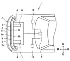
- the vehicle collision detection apparatus 1 of the present embodiment includes a bumper absorber 2 that is a shock absorbing member, a hollow detection tube member 3, a pressure sensor 4, a filling member 5, and a collision detection.
- An ECU 6 is provided.
- the vehicle collision detection device 1 detects a collision of an object (such as a pedestrian) with a bumper 7 provided in front of the vehicle.
- the bumper 7 is mainly composed of a bumper cover 8, a bumper absorber 2, and a bumper reinforcement 9.
- the bumper absorber 2 is provided on the front surface 9 a of the bumper reinforcement 9 and is disposed so as to surround the detection tube member 3.
- the bumper absorber 2 is a member responsible for shock absorption in the bumper 7, and is made of, for example, foamed polypropylene.
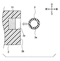
- a groove 2a for mounting the detection tube member 3 is formed on the rear surface 2b of the bumper absorber 2 (see FIG. 4).
- the groove 2a has a rectangular cross section and is formed along the vehicle width direction.
- the groove part 2a shall have a bending part in the middle of the vehicle width direction.
- the cross-sectional shape of the groove part 2a is not restricted to a rectangle, For example, circular and a polygon may be sufficient.
- the detection tube member 3 is a member having a hollow portion 3a formed therein and extending in the vehicle width direction (vehicle left-right direction), and is mounted in the groove portion 2a of the bumper absorber 2.
- the detection tube member 3 is disposed on the front surface 9a (the vehicle front side) of the bumper reinforcement 9 in the bumper 7 of the vehicle. Both ends of the detection tube member 3 are curved in a substantially U-shape and connected to a pressure sensor 4 to be described later on the left and right outer sides of the bumper reinforcement 9 in the vehicle width direction.
- the detection tube member 3 has a circular cross-sectional shape and is made of synthetic rubber, for example, silicone rubber.
- the outer diameter of the detection tube member 3 is assumed to be about 10 mm, for example.
- the cross-sectional shape of the detection tube member 3 is not limited to a circle, but may be a polygon such as a quadrangle.
- the material of the tube member 3 for detection may be ethylene propylene rubber (EPDM) or the like.
- the pressure sensor 4 is disposed on the vehicle rear side with respect to the front surface 9a of the bumper reinforcement 9. Specifically, two pressure sensors 4 are installed on the rear surface 9b of the left and right ends of the bumper reinforcement 9, and are fixedly attached by fastening bolts (not shown). In this embodiment, redundancy and detection accuracy are ensured by installing two pressure sensors 4 in this way.
- the pressure sensor 4 is connected to the left and right ends of the detection tube member 3 and configured to detect the pressure in the hollow portion 3 a of the detection tube member 3. .
- the pressure sensor 4 is a sensor device that detects a change in the pressure of the gas, and detects a change in the pressure of the air in the hollow portion 3 a of the detection tube member 3.
- the pressure sensor 4 is electrically connected to a collision detection ECU (Electronic Control Unit) 6 via a transmission line, and outputs a signal proportional to the pressure to the collision detection ECU 6.
- the collision detection ECU 6 detects a pedestrian collision with the bumper 7 based on the pressure detection result by the pressure sensor 4. Further, the collision detection ECU 6 is electrically connected to the pedestrian protection device 10.
- the pressure sensor 4 includes a main body portion 40, a sensor portion 41, a pressure introduction pipe 42, and a connector portion 43.
- the main body 40 is a box-shaped case for housing the sensor unit 41.
- the sensor unit 41 is made of a substrate provided with a sensor element for pressure detection.
- the pressure introduction tube 42 is a substantially cylindrical tube for introducing the pressure in the detection tube member 3 into the sensor unit 41, and is inserted into the hollow portion 3 a of the detection tube member 3 from the main body unit 40. .
- the sensor unit 41 detects a pressure change in the hollow portion 3 a of the detection tube member 3 through the pressure introduction tube 42.
- the sensor unit 41 is electrically connected to a connector 44 provided in the connector unit 43, and transmits a signal proportional to the pressure to the collision detection ECU 6 via the connector 44 and the signal line (see FIG. 1).
- a flexible filling member 5 is provided in a gap formed on the vehicle front side of the detection tube member 3 in the groove 2a of the bumper absorber 2 (FIGS. 3 and 4). reference).
- the filling member 5 is disposed so as to cover the vehicle front side of the outer peripheral portion of the detection tube member 3.
- the filling member 5 may be disposed so as to cover the vehicle rear side of the outer peripheral portion of the detection tube member 3, and covers the vehicle front side and the vehicle rear side of the outer peripheral portion of the detection tube member 3. You may arrange
- the filling member 5 is made of a thermoplastic resin such as a thermoplastic elastomer, and is a separate member from the detection tube member 3.
- the filling member 5 is filled over the entire vehicle width direction in the groove 2a after the detection tube member 3 is mounted in the groove 2a. Specifically, the filling member 5 heated and softened (liquefied) is poured into the groove 2a of the bumper absorber 2 to which the detection tube member 3 is attached. At this time, if the filling member 5 is poured with the front surface of the bumper absorber 2 shown in FIG. 4 facing down, the filling member 5 can be easily filled in the front side of the vehicle in the groove 2a.
- the softened filling member 5 eventually cools and hardens (solidifies) and is disposed at a predetermined position.
- the state in which the gap formed on the front side of the vehicle of the detection tube member 3 in the groove 2a can be maintained small.
- the material of the filling member 5 can be appropriately selected as long as it is a thermoplastic resin having flexibility.
- the collision detection ECU 6 is composed mainly of a CPU and controls the overall operation of the vehicle collision detection apparatus 1 and is electrically connected to the pressure sensor 4 and the pedestrian protection apparatus 10 (FIG. 1). reference).
- a pressure signal (pressure data) from the pressure sensor 4 is input to the collision detection ECU 6.
- the collision detection ECU 6 executes a predetermined collision determination process based on the pressure detection result (input signal) by the pressure sensor 4 and detects a collision of an object such as a pedestrian to the bumper 7, the pedestrian protection device 10. Is activated.
- the bumper 7 is for reducing a shock at the time of a vehicle collision, and includes a bumper cover 8, a bumper absorber 2, a bumper reinforcement 9, and the like.
- the bumper cover 8 is provided so as to cover the components of the bumper 7 and is a resin member such as polypropylene.
- the bumper cover 8 constitutes the appearance of the bumper 7 and at the same time constitutes a part of the appearance of the entire vehicle.
- the bumper reinforcement 9 is a rigid member made of metal such as aluminum that is disposed in the bumper cover 8 and extends in the vehicle width direction. As shown in FIG. A hollow member having a letter-shaped cross section.
- the bumper reinforcement 9 has a vehicle front side surface (front surface 9a) and a vehicle rear side surface (rear surface 9b). As shown in FIGS. 1 and 2, the bumper reinforcement 9 is attached to the front end of a side member 11 that is a pair of metal members extending in the vehicle front-rear direction.
- the pressure sensor 4 is disposed on the rear surface 9b of the bumper reinforcement 9, and an impact (external force) associated with a collision with a pedestrian or vehicle in front of the vehicle is provided in front of the vehicle. Direct transmission from the bumper cover 8 or the like to the pressure sensor 4 is protected by the presence of the bumper reinforcement 9.
- a pop-up hood is used as the pedestrian protection device 10.
- This pop-up hood raises the rear end of the engine hood instantly after detecting a vehicle collision, increases the clearance (clearance) between the pedestrian and hard parts such as the engine, and uses that space to make the pedestrian's head The impact energy on the pedestrian is absorbed and the impact on the pedestrian's head is reduced.
- a cowl airbag that cushions a pedestrian's impact by deploying an airbag from the engine hood outside the vehicle body to the lower part of the front window may be used.
- the operation at the time of collision of the vehicle collision detection apparatus 1 in the present embodiment will be described.
- the bumper cover 8 of the bumper 7 is deformed by an impact caused by the collision with the pedestrian.
- the bumper absorber 2 is deformed while absorbing the impact, and at the same time, the detection tube member 3 is also deformed.
- the pressure in the detection tube member 3 rapidly increases, and this pressure change is transmitted to the pressure sensor 4.
- the filling member 5 is filled in a gap formed on the vehicle front side of the detection tube member 3 in the groove 2a in the groove 2a of the bumper absorber 2 to which the detection tube member 3 is mounted. Therefore, the detection tube member 3 can be appropriately deformed with the deformation of the bumper absorber 2. That is, by disposing the filling member 5, the gap formed on the vehicle front side of the detection tube member 3 in the groove 2 a is not inhibited without inhibiting the deformation of the bumper absorber 2 and the detection tube member 3 at the time of collision. Variations can be eliminated, and collision detection can be performed accurately.
- the collision detection ECU 6 of the vehicle collision detection device 1 executes a predetermined collision determination process based on the detection result of the pressure sensor 4.
- this collision determination process for example, the effective mass of the collision object is calculated based on the detection results of the pressure sensor 4 and the vehicle speed sensor (not shown), and when this effective mass is larger than a predetermined threshold, the collision with the pedestrian is detected. It is determined that a collision has occurred with a pedestrian that requires operation of the pedestrian protection device 10 when the vehicle speed is within a predetermined range (for example, a range of 25 to 55 km / h). .
- the “effective mass” refers to a mass calculated using the relationship between momentum and impulse from the detection value of the pressure sensor 4 at the time of collision.
- the value of the detected pressure sensor 4 is different for a collision object having a mass different from that of a pedestrian. For this reason, by setting a threshold value between the effective mass of the human body and the mass of another assumed collision object, it is possible to classify the types of the collision object.
- This effective mass is calculated by dividing the integrated value of the pressure value detected by the pressure sensor 4 at a predetermined time by the vehicle speed, as shown in the following equation.
- M ( ⁇ P (t) dt) / V (Expression 1)
- M is an effective mass
- P is a value detected by the pressure sensor 4 at a predetermined time
- t is a predetermined time (for example, several ms to several tens of ms)
- V is a vehicle speed at the time of collision.
- E 1/2 ⁇ MV 2 representing the kinetic energy E of the collided object.
- the collision detection ECU 6 determines that a collision has occurred with a pedestrian that requires the pedestrian protection device 10 to operate, the collision detection ECU 6 outputs a control signal for operating the pedestrian protection device 10 to operate the pedestrian protection device 10. Let the impact on the pedestrian be reduced as described above.
- the vehicle collision detection apparatus 1 has a bumper absorber 2 that is an impact absorbing member disposed in a bumper 7 of the vehicle, and the bumper absorber 2 along the vehicle width direction.
- the detection tube member 3 that is mounted in the groove portion 2a formed in the above and has a hollow portion 3a formed inside the bumper reinforcement 9 on the vehicle front side, and the hollow portion 3a of the detection tube member 3
- a pressure sensor 4 for detecting the internal pressure, and detects a collision of an object (pedestrian) with the bumper 7 based on a pressure detection result by the pressure sensor 4.
- it has the filling part 5 with which the clearance gap formed in the vehicle front side of the tube member 3 for a detection in the groove part 2a is provided.
- the filling member 5 in the groove 2a formed in the bumper absorber 2 by providing the filling member 5 in the groove 2a formed in the bumper absorber 2, the variation in the gap formed on the vehicle front side of the detection tube member 3 in the groove 2a can be reduced. . Thereby, it can prevent that the deformation amount of the tube member 3 for a detection at the time of a collision with a vehicle and a pedestrian varies in the vehicle width direction, and the collision detection accuracy of the vehicle collision detection apparatus 1 can be improved.
- the size of the groove 2a of the plurality of manufactured bumper absorbers 2 is individually different.
- the gap formed on the vehicle front side or the rear side of the detection tube member 3 in the groove 2a can be prevented from varying between the bumper absorbers 2.
- the deformation amount of the detection tube member 3 at the time of the collision between the vehicle and the pedestrian, that is, the pressure detection result by the pressure sensor 4 can be prevented from varying depending on the size of each bumper absorber 2.
- the reliability of the collision detection accuracy by 1 can be improved.
- a bumper reinforcement 9 that is a rigid member is disposed on the vehicle rear side of the detection tube member 3, and a filling member is provided in a gap in the vehicle front-rear direction between the inner wall surface of the groove 2a and the detection tube member 3. Since 5 is filled, it can prevent reliably that the tube member 3 for a detection is bent to the vehicle rear side, and a collision detection can be performed correctly.
- the filling member 5 is made of a flexible member. According to this configuration, since the filling member 5 has flexibility, even if the filling member 5 is filled in the gap between the groove portion 2a and the detection tube member 3, the bumper absorber 2 and the detection tube at the time of collision. It does not hinder the member 3 from being deformed in the vehicle front-rear direction. Thereby, the collision detection accuracy of the vehicle collision detection apparatus 1 can be improved with certainty.
- the filling member 5 is supplied into the groove 2a separately from the detection tube member 3, and is filled in a gap formed on the vehicle front side of the detection tube member 3 in the groove 2a. According to this configuration, since the detection tube member 3 and the filling member 5 are separate, the groove member 2a of the bumper absorber 2 can be easily filled with the filling member 5 made of a softer material than the detection tube member 3. Can do.
- the filling member 5 is made of a thermoplastic resin and is characterized in that the groove member 2a is filled after the detection tube member 3 is mounted in the groove portion 2a. According to this configuration, the groove portion 2a in which the detection tube member 3 is mounted is filled with the filling member 5 softened (liquefied) by applying heat, so that the detection tube member 3 in the groove portion 2a is in front of the vehicle. The gap formed on the side can be reliably filled.
- the filling member 5 is arranged to cover the vehicle front side of the outer peripheral portion of the detection tube member 3. According to this configuration, by filling the filling member 5 on the vehicle front side of the detection tube member 3, the gap on the vehicle front side of the detection tube member 3 in the groove 2a can be efficiently reduced.
- the filling member 5 is provided over the entire vehicle width direction of the groove 2a. According to this configuration, by providing the filling member 5 over the entire vehicle width direction of the groove portion 2a, the variation in the clearance on the vehicle front side of the detection tube member 3 in the groove portion 2a can be reduced over the entire vehicle width direction. Thus, the collision detection accuracy of the vehicle collision detection apparatus 1 can be improved more effectively.
- the groove 2 a is provided on the rear surface 2 b of the bumper absorber 2. According to this configuration, the detection tube member 3 can be stably disposed on the vehicle front side of the bumper reinforcement 9 and the detection tube member 3 can be easily assembled to the bumper absorber 2.
- the pressure sensor 4 is fixed to the rear surface 9b of the bumper reinforcement 9. According to this configuration, since the pressure sensor 4 is fixed to the rear surface 9b (rear side of the vehicle) of the bumper reinforcement 9, even if a pedestrian or the like (object) collides with the vicinity of the left and right ends of the bumper 7, The impact is reduced by the bumper reinforcement 9, and the impact from the bumper cover 8 is not directly transmitted to the pressure sensor 4. For this reason, it is possible to prevent an external force from being applied to the pressure sensor 4 due to the deformation of the bumper cover 8 and the pressure sensor 4 to be damaged by the external force. Thereby, while being able to improve the tolerance of the collision detection apparatus 1 for vehicles, the reliability of the collision detection by the collision detection apparatus 1 for vehicles can be improved.
- the pressure sensor 4 is fixed to the rear surface 9b of the bumper reinforcement 9 by fastening bolts, the pressure sensor 4 can be securely fixed to the bumper reinforcement 9 and the pressure sensor 4 is It can be prevented from coming off or being damaged by external force.
- the filling member 51 is disposed on the vehicle front side in the groove 2a (see FIG. 7). Then, by inserting the detection tube member 3 into the back of the groove 2a (front of the vehicle) and mounting it, the filling member 51 is disposed so as to cover the vehicle front side of the outer periphery of the detection tube member 3 (FIG. 6).
- the filling member 51 is made of a soft resin such as soft polyurethane foam, and is softer than the bumper absorber 2 and the detection tube member 3.
- the filling member 51 is preferentially crushed and deformed, so that the detection tube member 3 in the groove portion 2a and the groove portion 2a in the vehicle front-rear direction are arranged.
- the gap can be reduced efficiently.
- the presence of the filling member 51 does not adversely affect the deformation of the bumper absorber 2 and the detection tube member 3 at the time of collision between the vehicle and the pedestrian.
- the filling member 51 is disposed in the groove portion 2a before the detection tube member 3 is attached to the groove portion 2a, and the detection tube member 3 is filled after the attachment.
- the member 51 is disposed so as to cover the vehicle front side of the outer peripheral portion of the detection tube member 3.
- the same effect as that of the first embodiment can be obtained, and the detection tube member 3 is attached to the groove portion 2a in which the filling member 51 is disposed in advance, thereby detecting the detection in the groove portion 2a. Since the gap on the vehicle front side of the tube member 3 can be reduced, the collision detection accuracy of the vehicle collision detection apparatus 1 can be improved with an easy manufacturing method and a simple configuration.
- the filling member 51 is made of a soft resin having flexibility, and is characterized by being a member softer than the bumper absorber 2 and the detection tube member 3. According to this configuration, even if the filling member 51 is disposed in the gap between the groove 2 a and the detection tube member 3, the filling member 51 is made of a softer material than the bumper absorber 2 and the detection tube member 3. At this time, the bumper absorber 2 and the detection tube member 3 are not adversely affected. Thereby, the collision detection accuracy of the vehicle collision detection apparatus 1 can be improved more reliably.
- the filling member 51 is supplied into the groove portion 2a separately from the detection tube member 3, and is filled (arranged) in the gap on the vehicle front side of the detection tube member 3 in the groove portion 2a. . According to this configuration, since the detection tube member 3 and the filling member 51 are separate, the filling member 5 made of a material softer than the bumper absorber 2 and the detection tube member 3 can be easily provided in the groove portion 2a of the bumper absorber 2. Can be arranged.
- the detection tube member 3 is disposed on the vehicle rear side of the bumper absorber 2 .
- the present invention is not limited to this, and the position where the detection tube member 3 is disposed. May be changed as appropriate.
- the detection tube member 3 may be disposed at the center upper portion of the bumper absorber 2 on the vehicle front side of the bumper reinforcement 9.
- the filling member 51 may not be disposed over the entire vehicle width direction in the groove 2a of the bumper absorber 2, and for example, a plurality of filling members 51 may be provided at predetermined intervals in the vehicle width direction. Furthermore, the material of the filling member 51 can be selected as appropriate as long as the material is softer than the bumper absorber 2 and the detection tube member 3.
- the filling member 51 was arrange
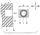
- a filling member 52 is integrally formed so as to cover the entire outer peripheral portion of the detection tube member 3 (see FIG. 10). The detection tube member 3 covered with the filling member 52 is fitted into the groove 2a and mounted (see FIG. 9).
- the detection member covered with the filling member 52 is longer than the length A in the vehicle front-rear direction of the groove portion 2a.
- the length B of the tube member 3 in the vehicle front-rear direction is longer.
- the detection tube member 3 covered with the filling member 52 is fitted into the groove 2 a and disposed on the front surface 9 a of the bumper reinforcement 9.
- the filling member 52 provided on the outer peripheral portion of the detection tube member 3 is preferentially crushed and deformed, gaps formed on the vehicle front side and the rear side of the detection tube member 3 in the groove portion 2a. It can be reduced efficiently. In this way, the assembly of the detection tube member 3 and the filling member 52 to the bumper absorber 2 (groove portion 2a) is completed.
- the filling member 52 is made of, for example, a soft polyurethane foam, and is softer than the bumper absorber 2 and the detection tube member 3 as in the second embodiment. For this reason, even if the detection tube member 3 covered with the filling member 52 is fitted into the groove 2a, there is no adverse effect on the deformation of the bumper absorber 2 and the detection tube member 3 at the time of collision. Further, it is assumed that the outer shape of the detection tube member 3 covered with the filling member 52 and the outer shape of the groove 2a are matched except for the length in the vehicle front-rear direction.
- the filling member 52 is integrated with the detection tube member 3 in advance, and is fitted into the groove portion 2a when the detection tube member 3 is inserted into the groove portion. By combining, it has filled the clearance gap formed in the vehicle front side and back side of the tube member 3 for a detection in the groove part 2a.
- the same effects as those of the first embodiment can be obtained, and the detection tube member 3 and the filling member 52 are integrated, so that the softening as in the first embodiment is achieved.
- a filling step for filling the filling member 5 is not required, the detection tube member 3 and the filling member 52 can be easily assembled to the bumper absorber 2, and the manufacturing process can be simplified.
- the filling member 52 is arranged so as to cover the entire outer peripheral portion of the detection tube member 3 before the detection tube member 3 is mounted in the groove 2a.
- the detection tube member 3 whose entire outer peripheral portion is covered with the filling member 52 is attached to the groove portion 2a, so that the detection tube member 3 in the groove portion 2a is formed on the vehicle front side and the rear side. Therefore, it is possible to reliably prevent variations in the deformation amount of the detection tube member 3 in the vehicle width direction at the time of collision between the vehicle and the pedestrian.
- the outer shape of the detection tube member 3 covered with the filling member 52 and the outer shape of the groove 2a are matched, the vehicle front side and the rear side of the detection tube member 3 in the groove 2a. The gap formed on the side can be eliminated more reliably. Thereby, the collision detection accuracy of the vehicle collision detection apparatus 1 can be further improved.
- the detection tube member 3 covered with the filling member 52 has a length B in the vehicle front-rear direction that is longer than a length A in the vehicle front-rear direction of the groove portion 2a. It is also characterized by being longer. According to this configuration, the fitting strength between the detection tube member 3 and the filling member 52 and the groove portion 2a can be improved, and the assembly property of the detection tube member 3 can be improved.
- the filling member 52 is a member having flexibility that is softer than the bumper absorber 2 and the tube member 3 for detection. According to this configuration, since the filling member 52 is made of a material softer than the bumper absorber 2 and the detection tube member 3, the gap formed on the front side and the rear side of the detection tube member 3 in the groove 2a is filled. Even if the member 52 is disposed, the deformation of the bumper absorber 2 and the detection tube member 3 at the time of a collision is not adversely affected. Thereby, the collision detection accuracy of the vehicle collision detection apparatus 1 can be improved with certainty.
- the filling member 52 is disposed so as to cover the entire outer peripheral portion of the detection tube member 3 .
- the present invention is not limited to this, and the filling member 52 is a detection tube. What is necessary is just to be arrange
- the length of the detection tube member 3 covered with the filling member 52 in the vehicle front-rear direction is longer than the length A of the groove portion 2a in the vehicle front-rear direction.
- the length B is not limited to this.
- the length B of the detection tube member 3 covered with the filling member 52 in the vehicle front-rear direction is equal to the length A of the groove 2a in the vehicle front-rear direction. It may be the same length.
- the present disclosure is not limited to the above-described embodiment, and various modifications or extensions can be made without departing from the gist of the present disclosure.
- two pressure sensors 4 are disposed on the left and right ends of the rear surface 9b of the bumper reinforcement 9, but the present invention is not limited to this, and the pressure sensor 4 can be disposed at an arbitrary position.
- the pressure sensor 4 may be disposed on the upper surface of the bumper reinforcement 9 or may be fixed to another rigid member.
Landscapes
- Engineering & Computer Science (AREA)
- Mechanical Engineering (AREA)
- Force Measurement Appropriate To Specific Purposes (AREA)
Abstract
L'invention porte sur un dispositif de détection de collision (1) pour un véhicule, lequel dispositif comporte : un absorbeur de pare-chocs (2), qui est un élément d'absorption d'impact installé dans un pare-chocs (7) du véhicule ; un élément de tube de détection (3) disposé dans une partie de rainure (2a) formée sur l'absorbeur de pare-chocs (2) le long de la direction de la largeur du véhicule, un élément de tube de détection (3) ayant une partie creuse (3a) formée à l'intérieur, et installé sur le côté avant de véhicule d'un renfort de pare-chocs (9) ; un capteur de pression (4) pour détecter la pression dans la partie creuse (3a) de l'élément de tube de détection (3) ; et une unité de commande électronique de détection de collision (6) pour détecter une collision d'un objet avec le pare-chocs (20) sur la base du résultat de la détection de pression par le capteur de pression (4). Le dispositif de détection de collision (1) pour un véhicule comporte un élément de rembourrage (5, 51, 52) rembourrant un espace formé sur le côté avant et/ou le côté arrière de véhicule de l'élément de tube de détection (3) dans la partie de rainure (2a).
Priority Applications (1)
| Application Number | Priority Date | Filing Date | Title |
|---|---|---|---|
| DE112015002888.9T DE112015002888T5 (de) | 2014-06-18 | 2015-06-08 | Kollisionserfassungsvorrichtung für ein Fahrzeug |
Applications Claiming Priority (2)
| Application Number | Priority Date | Filing Date | Title |
|---|---|---|---|
| JP2014-125588 | 2014-06-18 | ||
| JP2014125588A JP6233651B2 (ja) | 2014-06-18 | 2014-06-18 | 車両用衝突検知装置 |
Publications (1)
| Publication Number | Publication Date |
|---|---|
| WO2015194121A1 true WO2015194121A1 (fr) | 2015-12-23 |
Family
ID=54935131
Family Applications (1)
| Application Number | Title | Priority Date | Filing Date |
|---|---|---|---|
| PCT/JP2015/002859 Ceased WO2015194121A1 (fr) | 2014-06-18 | 2015-06-08 | Dispositif de détection de collision pour véhicule |
Country Status (3)
| Country | Link |
|---|---|
| JP (1) | JP6233651B2 (fr) |
| DE (1) | DE112015002888T5 (fr) |
| WO (1) | WO2015194121A1 (fr) |
Cited By (3)
| Publication number | Priority date | Publication date | Assignee | Title |
|---|---|---|---|---|
| WO2017122598A1 (fr) * | 2016-01-11 | 2017-07-20 | 株式会社デンソー | Dispositif de détection de collision destiné à un véhicule |
| CN107235026A (zh) * | 2016-03-28 | 2017-10-10 | 本田技研工业株式会社 | 车辆用保险杠 |
| CN109572608A (zh) * | 2017-09-29 | 2019-04-05 | 丰田自动车株式会社 | 传感器保护器和配备有其的车辆 |
Families Citing this family (4)
| Publication number | Priority date | Publication date | Assignee | Title |
|---|---|---|---|---|
| JP2017144806A (ja) | 2016-02-16 | 2017-08-24 | 株式会社デンソー | 車両用衝突検知装置及びその製造方法 |
| US10259412B1 (en) * | 2017-12-08 | 2019-04-16 | GM Global Technology Operations LLC | Bumper collision sensor for an automotive vehicle |
| JP7404963B2 (ja) * | 2020-03-24 | 2023-12-26 | 株式会社デンソー | チューブ式衝突検知センサ |
| CN113335212B (zh) * | 2021-05-28 | 2023-01-24 | 江铃汽车股份有限公司 | 一种安装支架及汽车 |
Citations (4)
| Publication number | Priority date | Publication date | Assignee | Title |
|---|---|---|---|---|
| JP2005247299A (ja) * | 2004-03-04 | 2005-09-15 | Trw Automotive Gmbh | 自動車のための歩行者保護装置 |
| JP2009023405A (ja) * | 2007-07-17 | 2009-02-05 | Denso Corp | 衝突検知センサ |
| WO2013131629A1 (fr) * | 2012-03-08 | 2013-09-12 | Daimler Ag | Véhicule avec une barre transversale flexible et une unité d'absorption de chocs |
| JP2014505629A (ja) * | 2011-02-22 | 2014-03-06 | コンチネンタル オートモーティヴ ゲゼルシャフト ミット ベシュレンクテル ハフツング | 柔軟に変形自在なチューブと少なくとも一つの圧力センサーを有する衝突センサー |
Family Cites Families (1)
| Publication number | Priority date | Publication date | Assignee | Title |
|---|---|---|---|---|
| JP5104715B2 (ja) * | 2008-10-21 | 2012-12-19 | 株式会社デンソー | 車両用衝突検知装置 |
-
2014
- 2014-06-18 JP JP2014125588A patent/JP6233651B2/ja not_active Expired - Fee Related
-
2015
- 2015-06-08 DE DE112015002888.9T patent/DE112015002888T5/de not_active Withdrawn
- 2015-06-08 WO PCT/JP2015/002859 patent/WO2015194121A1/fr not_active Ceased
Patent Citations (4)
| Publication number | Priority date | Publication date | Assignee | Title |
|---|---|---|---|---|
| JP2005247299A (ja) * | 2004-03-04 | 2005-09-15 | Trw Automotive Gmbh | 自動車のための歩行者保護装置 |
| JP2009023405A (ja) * | 2007-07-17 | 2009-02-05 | Denso Corp | 衝突検知センサ |
| JP2014505629A (ja) * | 2011-02-22 | 2014-03-06 | コンチネンタル オートモーティヴ ゲゼルシャフト ミット ベシュレンクテル ハフツング | 柔軟に変形自在なチューブと少なくとも一つの圧力センサーを有する衝突センサー |
| WO2013131629A1 (fr) * | 2012-03-08 | 2013-09-12 | Daimler Ag | Véhicule avec une barre transversale flexible et une unité d'absorption de chocs |
Cited By (4)
| Publication number | Priority date | Publication date | Assignee | Title |
|---|---|---|---|---|
| WO2017122598A1 (fr) * | 2016-01-11 | 2017-07-20 | 株式会社デンソー | Dispositif de détection de collision destiné à un véhicule |
| CN107235026A (zh) * | 2016-03-28 | 2017-10-10 | 本田技研工业株式会社 | 车辆用保险杠 |
| CN107235026B (zh) * | 2016-03-28 | 2019-07-16 | 本田技研工业株式会社 | 车辆用保险杠 |
| CN109572608A (zh) * | 2017-09-29 | 2019-04-05 | 丰田自动车株式会社 | 传感器保护器和配备有其的车辆 |
Also Published As
| Publication number | Publication date |
|---|---|
| JP6233651B2 (ja) | 2017-11-22 |
| DE112015002888T5 (de) | 2017-03-02 |
| JP2016002939A (ja) | 2016-01-12 |
Similar Documents
| Publication | Publication Date | Title |
|---|---|---|
| JP6233651B2 (ja) | 車両用衝突検知装置 | |
| JP6098897B2 (ja) | 車両用衝突検知装置 | |
| CN108698549A (zh) | 车辆用碰撞检测装置 | |
| JP6375978B2 (ja) | 車両用衝突検知装置 | |
| JP5967056B2 (ja) | 車両用衝突検知装置 | |
| JP6375907B2 (ja) | 車両用衝突検知装置 | |
| JP6201909B2 (ja) | 車両用衝突検知装置 | |
| JP6375896B2 (ja) | 車両用衝突検知装置 | |
| JP6481475B2 (ja) | 車両用衝突検知装置 | |
| JP6036636B2 (ja) | 車両用衝突検知装置 | |
| JP6413829B2 (ja) | 車両用衝突検知装置 | |
| JP6372691B2 (ja) | 車両用衝突検知装置 | |
| JP6376402B2 (ja) | 車両用衝突検知装置 | |
| WO2016075926A1 (fr) | Dispositif de détection de collision de véhicules | |
| JP6500532B2 (ja) | 車両用衝突検知装置 | |
| JP6432376B2 (ja) | 車両用衝突検知装置 | |
| JP2015081070A (ja) | 車両用衝突検知装置 | |
| JP5924548B2 (ja) | 車両用衝突検知装置 | |
| WO2016092793A1 (fr) | Dispositif de détection de collision de véhicule | |
| JP6447303B2 (ja) | 車両用衝突検知装置 | |
| JP2016120867A (ja) | 車両用衝突検知装置 | |
| JP6443686B2 (ja) | 車両用衝突検知装置 | |
| JP6443272B2 (ja) | 車両用衝突検知装置 | |
| WO2016157734A1 (fr) | Dispositif de détection de collision de véhicule |
Legal Events
| Date | Code | Title | Description |
|---|---|---|---|
| 121 | Ep: the epo has been informed by wipo that ep was designated in this application |
Ref document number: 15810352 Country of ref document: EP Kind code of ref document: A1 |
|
| WWE | Wipo information: entry into national phase |
Ref document number: 112015002888 Country of ref document: DE |
|
| 122 | Ep: pct application non-entry in european phase |
Ref document number: 15810352 Country of ref document: EP Kind code of ref document: A1 |