WO2015194399A1 - 三次元造形装置 - Google Patents
三次元造形装置 Download PDFInfo
- Publication number
- WO2015194399A1 WO2015194399A1 PCT/JP2015/066353 JP2015066353W WO2015194399A1 WO 2015194399 A1 WO2015194399 A1 WO 2015194399A1 JP 2015066353 W JP2015066353 W JP 2015066353W WO 2015194399 A1 WO2015194399 A1 WO 2015194399A1
- Authority
- WO
- WIPO (PCT)
- Prior art keywords
- unit
- drive unit
- dimensional modeling
- modeling apparatus
- drive
- Prior art date
- Legal status (The legal status is an assumption and is not a legal conclusion. Google has not performed a legal analysis and makes no representation as to the accuracy of the status listed.)
- Ceased
Links
Images


Classifications
-
- B—PERFORMING OPERATIONS; TRANSPORTING
- B22—CASTING; POWDER METALLURGY
- B22F—WORKING METALLIC POWDER; MANUFACTURE OF ARTICLES FROM METALLIC POWDER; MAKING METALLIC POWDER; APPARATUS OR DEVICES SPECIALLY ADAPTED FOR METALLIC POWDER
- B22F12/00—Apparatus or devices specially adapted for additive manufacturing; Auxiliary means for additive manufacturing; Combinations of additive manufacturing apparatus or devices with other processing apparatus or devices
- B22F12/22—Driving means
- B22F12/222—Driving means for motion along a direction orthogonal to the plane of a layer
-
- B—PERFORMING OPERATIONS; TRANSPORTING
- B22—CASTING; POWDER METALLURGY
- B22F—WORKING METALLIC POWDER; MANUFACTURE OF ARTICLES FROM METALLIC POWDER; MAKING METALLIC POWDER; APPARATUS OR DEVICES SPECIALLY ADAPTED FOR METALLIC POWDER
- B22F3/00—Manufacture of workpieces or articles from metallic powder characterised by the manner of compacting or sintering; Apparatus specially adapted therefor ; Presses and furnaces
- B22F3/10—Sintering only
- B22F3/105—Sintering only by using electric current other than for infrared radiant energy, laser radiation or plasma ; by ultrasonic bonding
-
- B—PERFORMING OPERATIONS; TRANSPORTING
- B22—CASTING; POWDER METALLURGY
- B22F—WORKING METALLIC POWDER; MANUFACTURE OF ARTICLES FROM METALLIC POWDER; MAKING METALLIC POWDER; APPARATUS OR DEVICES SPECIALLY ADAPTED FOR METALLIC POWDER
- B22F3/00—Manufacture of workpieces or articles from metallic powder characterised by the manner of compacting or sintering; Apparatus specially adapted therefor ; Presses and furnaces
- B22F3/12—Both compacting and sintering
- B22F3/16—Both compacting and sintering in successive or repeated steps
-
- B—PERFORMING OPERATIONS; TRANSPORTING
- B29—WORKING OF PLASTICS; WORKING OF SUBSTANCES IN A PLASTIC STATE IN GENERAL
- B29C—SHAPING OR JOINING OF PLASTICS; SHAPING OF MATERIAL IN A PLASTIC STATE, NOT OTHERWISE PROVIDED FOR; AFTER-TREATMENT OF THE SHAPED PRODUCTS, e.g. REPAIRING
- B29C64/00—Additive manufacturing, i.e. manufacturing of three-dimensional [3D] objects by additive deposition, additive agglomeration or additive layering, e.g. by 3D printing, stereolithography or selective laser sintering
- B29C64/10—Processes of additive manufacturing
- B29C64/171—Processes of additive manufacturing specially adapted for manufacturing multiple 3D objects
- B29C64/176—Sequentially
-
- B—PERFORMING OPERATIONS; TRANSPORTING
- B29—WORKING OF PLASTICS; WORKING OF SUBSTANCES IN A PLASTIC STATE IN GENERAL
- B29C—SHAPING OR JOINING OF PLASTICS; SHAPING OF MATERIAL IN A PLASTIC STATE, NOT OTHERWISE PROVIDED FOR; AFTER-TREATMENT OF THE SHAPED PRODUCTS, e.g. REPAIRING
- B29C64/00—Additive manufacturing, i.e. manufacturing of three-dimensional [3D] objects by additive deposition, additive agglomeration or additive layering, e.g. by 3D printing, stereolithography or selective laser sintering
- B29C64/10—Processes of additive manufacturing
- B29C64/171—Processes of additive manufacturing specially adapted for manufacturing multiple 3D objects
- B29C64/182—Processes of additive manufacturing specially adapted for manufacturing multiple 3D objects in parallel batches
-
- B—PERFORMING OPERATIONS; TRANSPORTING
- B29—WORKING OF PLASTICS; WORKING OF SUBSTANCES IN A PLASTIC STATE IN GENERAL
- B29C—SHAPING OR JOINING OF PLASTICS; SHAPING OF MATERIAL IN A PLASTIC STATE, NOT OTHERWISE PROVIDED FOR; AFTER-TREATMENT OF THE SHAPED PRODUCTS, e.g. REPAIRING
- B29C64/00—Additive manufacturing, i.e. manufacturing of three-dimensional [3D] objects by additive deposition, additive agglomeration or additive layering, e.g. by 3D printing, stereolithography or selective laser sintering
- B29C64/20—Apparatus for additive manufacturing; Details thereof or accessories therefor
- B29C64/205—Means for applying layers
-
- B—PERFORMING OPERATIONS; TRANSPORTING
- B29—WORKING OF PLASTICS; WORKING OF SUBSTANCES IN A PLASTIC STATE IN GENERAL
- B29C—SHAPING OR JOINING OF PLASTICS; SHAPING OF MATERIAL IN A PLASTIC STATE, NOT OTHERWISE PROVIDED FOR; AFTER-TREATMENT OF THE SHAPED PRODUCTS, e.g. REPAIRING
- B29C64/00—Additive manufacturing, i.e. manufacturing of three-dimensional [3D] objects by additive deposition, additive agglomeration or additive layering, e.g. by 3D printing, stereolithography or selective laser sintering
- B29C64/20—Apparatus for additive manufacturing; Details thereof or accessories therefor
- B29C64/227—Driving means
- B29C64/241—Driving means for rotary motion
-
- B—PERFORMING OPERATIONS; TRANSPORTING
- B29—WORKING OF PLASTICS; WORKING OF SUBSTANCES IN A PLASTIC STATE IN GENERAL
- B29C—SHAPING OR JOINING OF PLASTICS; SHAPING OF MATERIAL IN A PLASTIC STATE, NOT OTHERWISE PROVIDED FOR; AFTER-TREATMENT OF THE SHAPED PRODUCTS, e.g. REPAIRING
- B29C64/00—Additive manufacturing, i.e. manufacturing of three-dimensional [3D] objects by additive deposition, additive agglomeration or additive layering, e.g. by 3D printing, stereolithography or selective laser sintering
- B29C64/20—Apparatus for additive manufacturing; Details thereof or accessories therefor
- B29C64/25—Housings, e.g. machine housings
-
- B—PERFORMING OPERATIONS; TRANSPORTING
- B29—WORKING OF PLASTICS; WORKING OF SUBSTANCES IN A PLASTIC STATE IN GENERAL
- B29C—SHAPING OR JOINING OF PLASTICS; SHAPING OF MATERIAL IN A PLASTIC STATE, NOT OTHERWISE PROVIDED FOR; AFTER-TREATMENT OF THE SHAPED PRODUCTS, e.g. REPAIRING
- B29C64/00—Additive manufacturing, i.e. manufacturing of three-dimensional [3D] objects by additive deposition, additive agglomeration or additive layering, e.g. by 3D printing, stereolithography or selective laser sintering
- B29C64/20—Apparatus for additive manufacturing; Details thereof or accessories therefor
- B29C64/255—Enclosures for the building material, e.g. powder containers
-
- B—PERFORMING OPERATIONS; TRANSPORTING
- B29—WORKING OF PLASTICS; WORKING OF SUBSTANCES IN A PLASTIC STATE IN GENERAL
- B29C—SHAPING OR JOINING OF PLASTICS; SHAPING OF MATERIAL IN A PLASTIC STATE, NOT OTHERWISE PROVIDED FOR; AFTER-TREATMENT OF THE SHAPED PRODUCTS, e.g. REPAIRING
- B29C64/00—Additive manufacturing, i.e. manufacturing of three-dimensional [3D] objects by additive deposition, additive agglomeration or additive layering, e.g. by 3D printing, stereolithography or selective laser sintering
- B29C64/30—Auxiliary operations or equipment
- B29C64/307—Handling of material to be used in additive manufacturing
-
- B—PERFORMING OPERATIONS; TRANSPORTING
- B29—WORKING OF PLASTICS; WORKING OF SUBSTANCES IN A PLASTIC STATE IN GENERAL
- B29C—SHAPING OR JOINING OF PLASTICS; SHAPING OF MATERIAL IN A PLASTIC STATE, NOT OTHERWISE PROVIDED FOR; AFTER-TREATMENT OF THE SHAPED PRODUCTS, e.g. REPAIRING
- B29C64/00—Additive manufacturing, i.e. manufacturing of three-dimensional [3D] objects by additive deposition, additive agglomeration or additive layering, e.g. by 3D printing, stereolithography or selective laser sintering
- B29C64/40—Structures for supporting 3D objects during manufacture and intended to be sacrificed after completion thereof
-
- B—PERFORMING OPERATIONS; TRANSPORTING
- B29—WORKING OF PLASTICS; WORKING OF SUBSTANCES IN A PLASTIC STATE IN GENERAL
- B29C—SHAPING OR JOINING OF PLASTICS; SHAPING OF MATERIAL IN A PLASTIC STATE, NOT OTHERWISE PROVIDED FOR; AFTER-TREATMENT OF THE SHAPED PRODUCTS, e.g. REPAIRING
- B29C67/00—Shaping techniques not covered by groups B29C39/00 - B29C65/00, B29C70/00 or B29C73/00
-
- B—PERFORMING OPERATIONS; TRANSPORTING
- B33—ADDITIVE MANUFACTURING TECHNOLOGY
- B33Y—ADDITIVE MANUFACTURING, i.e. MANUFACTURING OF THREE-DIMENSIONAL [3D] OBJECTS BY ADDITIVE DEPOSITION, ADDITIVE AGGLOMERATION OR ADDITIVE LAYERING, e.g. BY 3D PRINTING, STEREOLITHOGRAPHY OR SELECTIVE LASER SINTERING
- B33Y10/00—Processes of additive manufacturing
-
- B—PERFORMING OPERATIONS; TRANSPORTING
- B33—ADDITIVE MANUFACTURING TECHNOLOGY
- B33Y—ADDITIVE MANUFACTURING, i.e. MANUFACTURING OF THREE-DIMENSIONAL [3D] OBJECTS BY ADDITIVE DEPOSITION, ADDITIVE AGGLOMERATION OR ADDITIVE LAYERING, e.g. BY 3D PRINTING, STEREOLITHOGRAPHY OR SELECTIVE LASER SINTERING
- B33Y30/00—Apparatus for additive manufacturing; Details thereof or accessories therefor
-
- B—PERFORMING OPERATIONS; TRANSPORTING
- B33—ADDITIVE MANUFACTURING TECHNOLOGY
- B33Y—ADDITIVE MANUFACTURING, i.e. MANUFACTURING OF THREE-DIMENSIONAL [3D] OBJECTS BY ADDITIVE DEPOSITION, ADDITIVE AGGLOMERATION OR ADDITIVE LAYERING, e.g. BY 3D PRINTING, STEREOLITHOGRAPHY OR SELECTIVE LASER SINTERING
- B33Y40/00—Auxiliary operations or equipment, e.g. for material handling
- B33Y40/10—Pre-treatment
-
- B—PERFORMING OPERATIONS; TRANSPORTING
- B33—ADDITIVE MANUFACTURING TECHNOLOGY
- B33Y—ADDITIVE MANUFACTURING, i.e. MANUFACTURING OF THREE-DIMENSIONAL [3D] OBJECTS BY ADDITIVE DEPOSITION, ADDITIVE AGGLOMERATION OR ADDITIVE LAYERING, e.g. BY 3D PRINTING, STEREOLITHOGRAPHY OR SELECTIVE LASER SINTERING
- B33Y40/00—Auxiliary operations or equipment, e.g. for material handling
- B33Y40/20—Post-treatment, e.g. curing, coating or polishing
-
- B—PERFORMING OPERATIONS; TRANSPORTING
- B33—ADDITIVE MANUFACTURING TECHNOLOGY
- B33Y—ADDITIVE MANUFACTURING, i.e. MANUFACTURING OF THREE-DIMENSIONAL [3D] OBJECTS BY ADDITIVE DEPOSITION, ADDITIVE AGGLOMERATION OR ADDITIVE LAYERING, e.g. BY 3D PRINTING, STEREOLITHOGRAPHY OR SELECTIVE LASER SINTERING
- B33Y50/00—Data acquisition or data processing for additive manufacturing
- B33Y50/02—Data acquisition or data processing for additive manufacturing for controlling or regulating additive manufacturing processes
-
- B—PERFORMING OPERATIONS; TRANSPORTING
- B33—ADDITIVE MANUFACTURING TECHNOLOGY
- B33Y—ADDITIVE MANUFACTURING, i.e. MANUFACTURING OF THREE-DIMENSIONAL [3D] OBJECTS BY ADDITIVE DEPOSITION, ADDITIVE AGGLOMERATION OR ADDITIVE LAYERING, e.g. BY 3D PRINTING, STEREOLITHOGRAPHY OR SELECTIVE LASER SINTERING
- B33Y70/00—Materials specially adapted for additive manufacturing
-
- B—PERFORMING OPERATIONS; TRANSPORTING
- B33—ADDITIVE MANUFACTURING TECHNOLOGY
- B33Y—ADDITIVE MANUFACTURING, i.e. MANUFACTURING OF THREE-DIMENSIONAL [3D] OBJECTS BY ADDITIVE DEPOSITION, ADDITIVE AGGLOMERATION OR ADDITIVE LAYERING, e.g. BY 3D PRINTING, STEREOLITHOGRAPHY OR SELECTIVE LASER SINTERING
- B33Y80/00—Products made by additive manufacturing
-
- B—PERFORMING OPERATIONS; TRANSPORTING
- B33—ADDITIVE MANUFACTURING TECHNOLOGY
- B33Y—ADDITIVE MANUFACTURING, i.e. MANUFACTURING OF THREE-DIMENSIONAL [3D] OBJECTS BY ADDITIVE DEPOSITION, ADDITIVE AGGLOMERATION OR ADDITIVE LAYERING, e.g. BY 3D PRINTING, STEREOLITHOGRAPHY OR SELECTIVE LASER SINTERING
- B33Y99/00—Subject matter not provided for in other groups of this subclass
-
- B—PERFORMING OPERATIONS; TRANSPORTING
- B22—CASTING; POWDER METALLURGY
- B22F—WORKING METALLIC POWDER; MANUFACTURE OF ARTICLES FROM METALLIC POWDER; MAKING METALLIC POWDER; APPARATUS OR DEVICES SPECIALLY ADAPTED FOR METALLIC POWDER
- B22F10/00—Additive manufacturing of workpieces or articles from metallic powder
- B22F10/20—Direct sintering or melting
- B22F10/28—Powder bed fusion, e.g. selective laser melting [SLM] or electron beam melting [EBM]
-
- B—PERFORMING OPERATIONS; TRANSPORTING
- B22—CASTING; POWDER METALLURGY
- B22F—WORKING METALLIC POWDER; MANUFACTURE OF ARTICLES FROM METALLIC POWDER; MAKING METALLIC POWDER; APPARATUS OR DEVICES SPECIALLY ADAPTED FOR METALLIC POWDER
- B22F10/00—Additive manufacturing of workpieces or articles from metallic powder
- B22F10/30—Process control
-
- B—PERFORMING OPERATIONS; TRANSPORTING
- B29—WORKING OF PLASTICS; WORKING OF SUBSTANCES IN A PLASTIC STATE IN GENERAL
- B29C—SHAPING OR JOINING OF PLASTICS; SHAPING OF MATERIAL IN A PLASTIC STATE, NOT OTHERWISE PROVIDED FOR; AFTER-TREATMENT OF THE SHAPED PRODUCTS, e.g. REPAIRING
- B29C64/00—Additive manufacturing, i.e. manufacturing of three-dimensional [3D] objects by additive deposition, additive agglomeration or additive layering, e.g. by 3D printing, stereolithography or selective laser sintering
- B29C64/10—Processes of additive manufacturing
- B29C64/141—Processes of additive manufacturing using only solid materials
- B29C64/147—Processes of additive manufacturing using only solid materials using sheet material, e.g. laminated object manufacturing [LOM] or laminating sheet material precut to local cross sections of the 3D object
-
- B—PERFORMING OPERATIONS; TRANSPORTING
- B29—WORKING OF PLASTICS; WORKING OF SUBSTANCES IN A PLASTIC STATE IN GENERAL
- B29C—SHAPING OR JOINING OF PLASTICS; SHAPING OF MATERIAL IN A PLASTIC STATE, NOT OTHERWISE PROVIDED FOR; AFTER-TREATMENT OF THE SHAPED PRODUCTS, e.g. REPAIRING
- B29C64/00—Additive manufacturing, i.e. manufacturing of three-dimensional [3D] objects by additive deposition, additive agglomeration or additive layering, e.g. by 3D printing, stereolithography or selective laser sintering
- B29C64/10—Processes of additive manufacturing
- B29C64/141—Processes of additive manufacturing using only solid materials
- B29C64/153—Processes of additive manufacturing using only solid materials using layers of powder being selectively joined, e.g. by selective laser sintering or melting
-
- B—PERFORMING OPERATIONS; TRANSPORTING
- B29—WORKING OF PLASTICS; WORKING OF SUBSTANCES IN A PLASTIC STATE IN GENERAL
- B29C—SHAPING OR JOINING OF PLASTICS; SHAPING OF MATERIAL IN A PLASTIC STATE, NOT OTHERWISE PROVIDED FOR; AFTER-TREATMENT OF THE SHAPED PRODUCTS, e.g. REPAIRING
- B29C64/00—Additive manufacturing, i.e. manufacturing of three-dimensional [3D] objects by additive deposition, additive agglomeration or additive layering, e.g. by 3D printing, stereolithography or selective laser sintering
- B29C64/20—Apparatus for additive manufacturing; Details thereof or accessories therefor
- B29C64/227—Driving means
- B29C64/232—Driving means for motion along the axis orthogonal to the plane of a layer
-
- B—PERFORMING OPERATIONS; TRANSPORTING
- B29—WORKING OF PLASTICS; WORKING OF SUBSTANCES IN A PLASTIC STATE IN GENERAL
- B29C—SHAPING OR JOINING OF PLASTICS; SHAPING OF MATERIAL IN A PLASTIC STATE, NOT OTHERWISE PROVIDED FOR; AFTER-TREATMENT OF THE SHAPED PRODUCTS, e.g. REPAIRING
- B29C64/00—Additive manufacturing, i.e. manufacturing of three-dimensional [3D] objects by additive deposition, additive agglomeration or additive layering, e.g. by 3D printing, stereolithography or selective laser sintering
- B29C64/20—Apparatus for additive manufacturing; Details thereof or accessories therefor
- B29C64/245—Platforms or substrates
-
- Y—GENERAL TAGGING OF NEW TECHNOLOGICAL DEVELOPMENTS; GENERAL TAGGING OF CROSS-SECTIONAL TECHNOLOGIES SPANNING OVER SEVERAL SECTIONS OF THE IPC; TECHNICAL SUBJECTS COVERED BY FORMER USPC CROSS-REFERENCE ART COLLECTIONS [XRACs] AND DIGESTS
- Y02—TECHNOLOGIES OR APPLICATIONS FOR MITIGATION OR ADAPTATION AGAINST CLIMATE CHANGE
- Y02P—CLIMATE CHANGE MITIGATION TECHNOLOGIES IN THE PRODUCTION OR PROCESSING OF GOODS
- Y02P10/00—Technologies related to metal processing
- Y02P10/25—Process efficiency
Definitions
- the present invention relates to a three-dimensional modeling apparatus for manufacturing a three-dimensional modeled object by repeatedly forming powder in a layered manner.
- the object of the present invention is to provide a three-dimensional modeling apparatus with high accuracy and productivity.
- the three-dimensional modeling apparatus of one embodiment according to the present invention is A support frame; A material supply unit supported by the support frame; A modeling object mounting unit on which a material supported by the support frame and supplied from the material supply unit is mounted; An input unit for inputting in advance an instruction movement amount of the table; A storage unit that stores an instruction movement amount input from the input unit; A control unit for controlling the material supply unit and the modeling object placing unit; With The shaped article placing part is A table on which the model is placed; A drive unit for driving the table; Have The control unit is configured to move the table by an instruction movement amount stored in the storage unit.
- the control unit feeds back a status signal of the driving unit.
- the drive unit includes a first drive unit and a second drive unit that can be driven independently,
- the control unit controls the first driving unit and the second driving unit independently of each other.
- the shaped article placing part is The apparatus further includes a transmission unit having a first transmission unit and a second transmission unit that transmit the driving forces of the first driving unit and the second driving unit to the slider, respectively.
- the drive unit includes the first drive unit, the second drive unit, the third drive unit, and the fourth drive unit that are arranged at positions that form a quadrangle
- the control unit can independently control the first drive unit, the second drive unit, the third drive unit, and the fourth drive unit.
- the three-dimensional modeling apparatus of one embodiment according to the present invention is A rod that moves with the table; A limit switch that contacts when the rod reaches a predetermined position; Is provided.
- FIG. 1 shows the three-dimensional modeling apparatus of one Embodiment concerning this invention. It is an enlarged view which shows the modeling mounting part of the three-dimensional modeling apparatus of this embodiment. It is the schematic which shows arrangement
- FIG. 1 is a diagram showing a three-dimensional modeling apparatus according to an embodiment of the present invention.
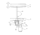
- the three-dimensional modeling apparatus 1 of the present embodiment includes an energy beam irradiation unit 2 as a material supply unit, a powder supply unit 3 as a material supply unit, and a modeling object placing unit 4.
- the energy beam irradiation unit 2, the powder supply unit 3, and the modeled article placement unit 4 are supported by the support frame 11. Further, a reference frame 12 as a part of the support frame 11 is formed at an intermediate portion of the support frame 11.
- the energy beam irradiation unit 2 includes a beam generation unit 21 that generates an energy beam EB, and a beam scanning unit 22 that adjusts the focal position of the energy beam EB irradiated from the beam generation unit 21 and that can perform two-dimensional scanning. And is placed on the support frame 11.
- the beam operation unit 22 performs two-dimensional scanning, but may perform three-dimensional scanning that can operate the focal position of the beam in the vertical direction.
- the beam generator 21 is preferably one that generates a laser beam or an electron beam.
- the beam scanning unit 22 moves an optical element such as a lens to focus the light on a metal powder M on a table, which will be described later, and performs two-dimensional scanning on the table 41.
- the energy beam irradiation unit 2 may be configured as a laser irradiation unit described in Patent Document 1.
- the beam scanning unit 22 focuses the electron beam by controlling the electromagnetic field and performs two-dimensional scanning on the table 41.
- the energy beam irradiation unit 2 may be configured as an apparatus for irradiating and guiding an electron beam described in Patent Document 2.
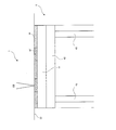
- the powder supply unit 3 includes a powder storage unit 31 that temporarily stores the metal powder M, a leveling unit 32 that averages the metal powder M on the table, and an outer frame unit 33.
- the powder storage unit 31 includes a container held by the support frame 11, has an injection unit 31 a for injecting the metal powder M on the upper side, and a discharge unit 31 b for discharging the metal powder M on the lower side. It is preferable that the discharge part 31b can adjust the discharge amount of the metal powder M.
- the leveling part 32 is a part that forms a plane having a uniform height as much as possible by moving a member such as a scraper on the table 41 with the metal powder M discharged from the powder storage part 31. In addition, it is preferable that the height which levels the metal powder M can be adjusted.
- the outer frame portion 33 is supported by the support frame 11 and is installed on the outer periphery of a table 41 described later. Excess metal powder M after the leveling portion 32 is leveled moves to the outer frame portion 33. These metal powders M are preferably circulated by a circulation unit (not shown) that returns to the powder storage unit 31.
- the powder supply unit 3 may be provided with a circulation unit (not shown) that returns the metal powder M on the table 41 that has not been formed to the powder storage unit 31 after being discharged from the discharge unit 31b.
- the material supply unit is not limited to the energy beam irradiation unit 2 and the powder supply unit 3 as in the present embodiment, but a form in which a sheet or tape-like resin, paper, metal, or the like is bonded, a form in which a liquid is cured, an inkjet head A form in which a solid or a liquid is sprayed and bonded using a metal, a form in which filaments are deposited and welded, a form in which metal powder is welded, or the like may be used.
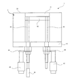
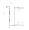
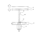
- FIG. 2 is an enlarged view showing a modeling placement portion of the three-dimensional modeling apparatus of the present embodiment.
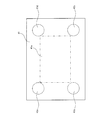
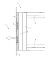
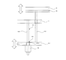
- FIG. 3 is a schematic diagram showing the arrangement of the drive transmission unit of the three-dimensional modeling apparatus of this embodiment.
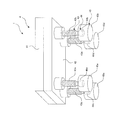
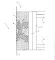
- FIG. 4 is a schematic perspective view showing a modeling placement part of the three-dimensional modeling apparatus of this embodiment.
- the molded article placement unit 4 includes a table 41, a slider 42, a ball screw 43, a speed reduction unit 44, a table driving unit 45, a rod 48, and a limit switch 49.
- the table 41 is supported by the slider 42.
- the upper surface of the table 41 is formed in a flat surface, and the metal powder M shown in FIG. 1 is discharged and placed on the upper surface.
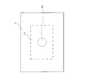
- the modeled object is preferably formed in a modeled area 41 a that is smaller than the outer shape of the table 41.
- the slider 42 supports the table 41 on the upper surface. Below, it is supported by the ball screw 43.
- the ball screw 43 is connected to the drive unit 45 via the speed reduction unit 44.
- the drive unit 45 includes a servo motor or other actuator, and the ball screw 43 rotates when the drive unit 45 is driven.
- the table 42 also moves up and down as the slider 42 moves up and down as the ball screw 43 rotates. .
- the ball screw 43 preferably penetrates the reference frame 12.
- the ball screw 43, the speed reduction part 44, and the drive part 45 are each arrange
- the ball screw 43 and the speed reduction part 44 comprise a transmission part.
- the drive unit 45 and the transmission unit constitute a drive transmission unit.
- the linear motion mechanism of the drive part 45 and the ball screw 43 may be sufficient without using the deceleration part 44. In the case of the linear motion mechanism, the backlash can be suppressed, so that the control can be performed with higher accuracy.
- the first ball screw 43a, the second ball screw 43b, the third ball screw 43c, and the fourth ball screw 43d are connected to the slider 42 corresponding to four corners outside the modeling region 41a.
- the first drive unit 45a, the second drive unit 45b, the third drive unit 45c, and the fourth drive unit 45d are respectively a first reduction unit 44a, a second reduction unit 44b, and a third reduction unit.
- the first ball screw 43a, the second ball screw 43b, the third ball screw 43c, and the fourth ball screw 43d are connected to each other via the 44c and the fourth reduction portion 44d.
- a rod 48 is attached to at least one of the first ball screw 43a, the second ball screw 43b, the third ball screw 43c, and the fourth ball screw 43d.
- the rod 48 moves together with the table 41, the slider 42, and the ball screw 43.
- a limit switch 49 is disposed below the rod 48. Therefore, if the table 41, the slider 42, the ball screw 43, and the rod 48 have a large amount of downward movement or a large amount of upward movement, the limit switch 49 is actuated to notify the danger.
- FIG. 5 is a diagram illustrating a control system of the three-dimensional modeling apparatus 1 of the present embodiment.
- control unit 50 receives the signals input from the input unit 51 and the storage unit 52 by the first driving unit 45a, the second driving unit 45b, and the second driving unit 45b.
- the third drive unit 45c and the fourth drive unit 45d are independently controlled.
- the input unit 51 inputs information such as a molding shape, a molding pressure, and a molding speed in advance.
- the storage unit 52 stores information input from the input unit 51, a modeling process, and the like, and outputs the information to the control unit 50.
- the rotation angle of the motor may be converted into a stroke amount in advance and stored in the storage unit 52, and open control may be performed so that all axes are parallel.
- a motor encoder (not shown) may be used as the input unit 51 to convert the rotation angle of the motor into a stroke amount and input it to the control unit 50 for feedback control.
- first drive unit 45a, the second drive unit 45b, the third drive unit 45c, and the fourth drive unit 45d feed back signals such as current, rotation speed, and rotation torque to the control unit 50.
- 6 to 9 are enlarged views showing the operation of the modeling table portion of the three-dimensional modeling apparatus of this embodiment.
- each drive unit 45 shown in FIG. 4 is driven, and the table 41 is moved downward as shown in FIG.
- the instruction movement amount in the table 41 may be input in advance to the input unit 51 shown in FIG. 5 and stored in the storage unit 52.
- the first drive unit 45a, the second drive unit 45b, and the third drive unit 45a are moved while the table 41 is moved by the indicated movement amount stored in the storage unit 52.
- Signals such as current, rotation speed, and rotation torque of the drive unit 45 c and the fourth drive unit 45 d are input to the control unit 50.
- the control unit 50 controls the first driving unit 45a, the second driving unit 45b, the third driving unit 45c, and the fourth driving unit 45d independently from these signals, and controls the table 41 to a predetermined posture. .
- the table 41 is controlled horizontally.
- the metal powder M is discharged onto the table 41 from the discharge part 31 b of the powder storage part 31.
- the metal powder M is uniformly leveled on the table 41 by the leveling unit 32 so that the surface is horizontal.
- the energy beam irradiation unit 2 shown in FIG. 1 irradiates the energy beam EB, and as shown in FIG. 7, the metal powder M is sintered to form a part of the modeled object M ′.
- each drive unit 45 shown in FIG. 4 is driven again, and the table 41 is moved downward as shown in FIG.
- the movement amount of the table 41 may be input in advance to the input unit 51 illustrated in FIG. 5 and stored in the storage unit 52.
- the first drive unit 45a and the second drive are performed while the table 41 is moved by the indicated movement amount stored in the storage unit 52.
- Signals such as current, rotation speed, and rotation torque of the unit 45b, the third drive unit 45c, and the fourth drive unit 45d are input to the control unit 50.
- the control unit 50 controls the first drive unit 45a, the second drive unit 45b, the third drive unit 45c, and the fourth drive unit 45d independently from these signals to control the table 41 to a predetermined posture.
- the table 41 is controlled horizontally.
- the metal powder M is discharged onto the table 41 from the discharge part 31 b of the powder storage part 31.
- the metal powder M is uniformly leveled on the table 41 by the leveling unit 32 so that the surface is horizontal.
- the energy beam irradiation unit 2 shown in FIG. 1 irradiates the energy beam EB, and as shown in FIG. 9, the metal powder M is sintered to form a part of the shaped object M ′.
- FIG. 10 is a diagram illustrating a state in which a modeled object is formed by the three-dimensional modeling apparatus according to the present embodiment.
- a modeled object M ′ is formed as shown in FIG.
- the posture of the table 41 can be set in many patterns. It is possible to form many types of shaped objects M ′.
- first drive unit 45a, the second drive unit 45b, the third drive unit 45c, and the fourth drive unit 45d can be controlled independently to control the table 41 in a predetermined posture, Can be formed with high accuracy.
- control unit 50 controls the table 41 horizontally by independently controlling the first drive unit 45a, the second drive unit 45b, the third drive unit 45c, and the fourth drive unit 45d, so It becomes possible to form an accurate shaped object M ′.
- FIG. 11 is a diagram showing a three-dimensional modeling apparatus according to another embodiment of the present invention.
- FIG. 12 is a schematic diagram illustrating an arrangement of a drive transmission unit of a three-dimensional modeling apparatus according to another embodiment.
- the fifth drive unit 45e, the fifth reduction unit 44e, and the fifth ball screw 43e are arranged below the center of the table 41. And it is preferable to control all the five drive parts 45 independently.
- the table 41 is supported at the five positions and driven by the five driving units 45, so that the molded object M 'can be formed with higher accuracy.
- the level of the table 41 can be maintained with higher accuracy, and a model M 'with higher accuracy can be formed. Furthermore, it becomes possible to place a large-sized model with a high weight and a large area.
- FIG. 13 is a schematic view showing the arrangement of the drive transmission unit of the three-dimensional modeling apparatus according to another embodiment.
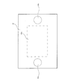
- one first ball screw 43a is provided. And it is preferable to control each one drive part 45 which is not shown in figure.
- the first ball screw 43a that supports the table 41 is disposed at the position of the center of gravity of the table 41 because the table 41 becomes stable.
- FIG. 14 is a schematic view showing the arrangement of the drive transmission unit of the three-dimensional modeling apparatus according to another embodiment.
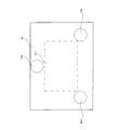
- At least two first ball screws 43a and second ball screws 43b are provided. And it is preferable to control all the two drive parts 45 which are not shown in figure independently.
- first ball screw 43a and the second ball screw 43b are arranged so that the straight line connecting the first ball screw 43a and the second ball screw 43b that supports the table 41 includes the center of gravity of the table 41, because the table 41 becomes stable.
- FIG. 15 is a schematic view showing the arrangement of the drive transmission unit of the three-dimensional modeling apparatus according to another embodiment.
- the third ball screw 43c is disposed so as to form a triangle with the first ball screw 43a and the second ball screw 43b. It is preferable to control all three drive units 45 (not shown) independently.
- the table 41 is supported at three positions and driven by the three driving units 45 (not shown), so that the plane is fixed and stabilized, and the number of the ball screw 43, the speed reduction unit 44, and the driving unit 45 is increased. Therefore, it is possible to form the modeled object M ′ at a low cost.
- first ball screw 43a, the second ball screw 43b, and the third ball screw 43a, the third ball screw 43b, and the third ball screw 43c that support the table 41 include the center of gravity of the table 41 so that the triangle formed by the triangle is formed. It is preferable to arrange the ball screw 43c because the table 41 is stabilized.
- FIG. 16 is a schematic view showing the structure of the drive transmission unit of the three-dimensional modeling apparatus of this embodiment.
- the table 41 is moved up and down via the slider 42 by rotating the screw portion 432 of the ball screw 43 by the driving force of the drive portion 45 and moving the nut portion 431 up and down.
- the nut portion 431 and the table 41 may be directly connected.
- the nut 431a is accommodated inside, and the outer case 431b is fixed to the slider 42.
- the nut 431a is rotatable with respect to the case 431b.
- the screw part 432 is rotatably fixed to the slider 42 at the upper part, is screwed with the nut 431a immediately below the slider 42, and is connected to the speed reducer 44 via a coupling at the lower part. Further, the screw portion 432 passes through a spline nut 433 that is fixed to the reference frame 12.
- the driving force generated from the driving unit 45 rotates the screw part 432 via the speed reducing unit 44.
- the screw part 432 rotates
- the nut 431a of the nut part 431 rotates. Since the nut portion 431 can move up and down along the screw portion 432, when the nut 431a rotates, the slider 42 moves up and down and the table 41 moves up and down.
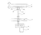
- FIG. 17 is a schematic diagram illustrating a structure of a drive transmission unit of a three-dimensional modeling apparatus according to another embodiment.
- the screw portion 432 of the ball screw 43 is rotated by the driving force of the drive portion 45 and the nut portion 431 is moved up and down to move the movable frame 411 up and down, and the rod 412 and the slider 42 are moved. Then, the table 41 is moved up and down.
- the rod 412 and the table 41 may be directly connected.
- the nut 431a is accommodated inside, and the outer case 431b is attached to the movable frame 411 integrally.
- the screw part 432 is fixed to the support frame 11 at the upper part, penetrates through the movable frame 411, is screwed with the nut 431a immediately below the movable frame 411, and is connected to the speed reducer 44 through a coupling at the lower part.
- the driving force generated from the driving unit 45 rotates the screw part 432 via the speed reducing unit 44.
- the screw part 432 rotates
- the nut 431a of the nut part 431 rotates. Since the nut portion 431 can move up and down along the screw portion 432, when the nut 431 a rotates, the slider 42 moves up and down via the movable frame 411 and the rod 412, and the table 41 moves up and down.
- FIG. 18 is a schematic diagram illustrating the structure of the drive transmission unit of the three-dimensional modeling apparatus according to the present embodiment.
- the nut 431 a of the nut portion 431 is rotated by the driving force of the driving portion 45, and the screw portion 432 of the ball screw 43 is moved up and down, whereby the table is interposed via the slider 42. 41 is moved up and down.
- the screw part 432 and the table 41 may be directly connected.
- the nut portion 431 contains a nut 431a on the inner side, the outer case 431b is fixed to the nut support portion 41b fixed to the reference frame 12, and cannot move up and down.
- the nut 431a is rotatable with respect to the case 431b.
- the screw portion 432 is rotatably fixed to the table 41 at the upper portion, and is screwed with the nut 431a at the lower portion. Further, the screw portion 432 passes through a spline nut 433 that is fixed to the reference frame 12.
- the first pulley 401 is fixed to the output shaft 44a of the deceleration unit 44.
- a second pulley 402 is fixed to the nut 431a.
- the first pulley 401 and the second pulley 402 are connected by a connecting belt 401.
- the second pulley 402 rotates together with the nut 431 a of the nut portion 431 and penetrates the screw portion 432.
- the driving force generated from the drive unit 45 is output to the first pulley 401 via the output shaft 44a of the speed reduction unit 44.
- the second pulley 402 rotates through the connecting belt 401.
- the nut 431a of the nut portion 431 rotates. Since the nut portion 431 cannot move up and down, when the nut 431a rotates, the screw portion 432 moves up and down. Therefore, the table 41 moves up and down.
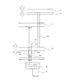
- FIG. 19 is a schematic diagram illustrating the structure of a drive transmission unit of a three-dimensional modeling apparatus according to another embodiment.
- the nut 431 a of the nut portion 431 is rotated by the driving force of the drive portion 45, and the nut portion 431 of the ball screw 43 is moved up and down relative to the screw portion 432, thereby moving the movable frame 411 up and down.
- the table 41 is moved up and down via the rod 412 and the slider 42.
- the rod 412 and the table 41 may be directly connected.
- the nut portion 431 has a nut 431a accommodated inside, and an outer case 431b is fixed to a nut support portion 41b fixed to the movable frame 411, and is attached to the movable frame 411 integrally.
- the drive unit 45 and the speed reduction unit 44 are also integrally attached to the movable frame 411 and move up and down together with the movable frame 411.
- the screw part 432 is fixed to the support frame 11 at the upper part and is screwed with the nut 431a at the lower part. Further, the screw portion 432 passes through a spline nut 433 fixed to the movable frame 411.
- the first pulley 401 is fixed to the output shaft 44a of the deceleration unit 44.
- a second pulley 402 is fixed to the nut 431a.
- the first pulley 401 and the second pulley 402 are connected by a connecting belt 401.
- the second pulley 402 rotates together with the nut 431 a of the nut portion 431 and penetrates the screw portion 432.
- the driving force generated from the drive unit 45 is output to the first pulley 401 via the output shaft 44a of the speed reduction unit 44.
- the first pulley 401 rotates
- the second pulley 402 rotates through the connecting belt 401.
- the nut 431a of the nut portion 431 rotates.
- the screw portion 432 cannot move up and down, so the nut 431a moves up and down. Therefore, the movable frame 411 moves up and down together with the nut portion 431, and the slider 42 and the table 41 connected by the rod 412 move up and down.
- FIG. 20 is a schematic diagram illustrating a structure of a drive transmission unit of a three-dimensional modeling apparatus according to another embodiment.
- a hollow direct drive motor is used as the drive unit 45, the nut 431a is rotated, and the screw part 432 of the ball screw 43 is moved up and down to move the table 41 through the slider 42. Move up and down.
- the screw part 432 and the table 41 may be directly connected.
- the driving unit 45 drives the nut 431a with a hollow direct drive motor, and passes the screw part 432 in the center.
- the nut portion 431 contains a nut 431a inside and is fixed to the reference frame 12 so as not to move up and down.
- the nut 431a is rotatable with respect to the case 431b.
- the screw portion 432 is rotatably fixed to the table 41 at the upper portion, and is screwed with the nut 431a at the lower portion.
- the driving unit 45 When the driving unit 45 generates a driving force, the nut 431a of the nut unit 431 rotates. Since the nut portion 431 cannot move up and down, when the nut 431a rotates, the screw portion 432 moves up and down. Therefore, the table 41 moves up and down.
- FIG. 21 is a schematic view showing a structure of a drive transmission unit of a three-dimensional modeling apparatus according to another embodiment.
- a hollow direct drive motor is used as the drive unit 45, the nut 431a is rotated, and the screw part 432 of the ball screw 43 is moved up and down to move the movable frame 411 up and down.
- the table 41 is moved up and down via 412 and the slider 42.
- the rod 412 and the table 41 may be directly connected.
- the driving unit 45 drives the nut 431a with a hollow direct drive motor, and passes the screw part 432 in the center.
- the nut 431a is accommodated inside, and the outer case 431b is fixed to the movable frame 411.
- the nut 431a is rotatable with respect to the case 431b.
- the screw part 432 is fixed to the frame 11 at the upper part and is screwed with the nut 431a at the lower part.
- the driving unit 45 When the driving unit 45 generates a driving force, the nut 431a of the nut unit 431 rotates. When the nut 431 a rotates, the nut 431 moves up and down along the screw part 432. Therefore, the movable frame 411 moves up and down together with the nut portion 431, and the slider 42 and the table 41 connected by the rod 412 move up and down.
- control system in the arrangement and structure of the drive transmission unit of the three-dimensional modeling apparatus 1 of another embodiment may be the same as that described in FIG.
- Modeling object placement unit 4 input unit 51 that inputs the instruction movement amount of the table 41 in advance, storage unit 52 that stores the instruction movement amount input from the input unit 41, the material supply unit 3, and the modeling object And a control unit 50 that controls the mounting unit 4, and the modeled object mounting unit 4 includes a table 41 on which a modeled object is mounted and a driving unit 45 that drives the table 41. Since the table 41 is moved by the indicated movement amount stored in the storage unit 52, it is possible to provide a three-dimensional modeling apparatus with high accuracy and productivity.
- control unit 50 can feed back the state signal of the driving unit 45, so that it can be controlled with higher accuracy.
- the drive unit 45 includes a first drive unit 45a and a second drive unit 45b that can be driven independently, and the control unit 50 includes the first drive unit 45a and the second drive unit 45b. Since the drive units 45b are independently controlled, it is possible to provide a three-dimensional modeling apparatus with high accuracy and productivity.
- the modeling object placing unit 4 includes the first ball screw 43a and the second ball that transmit the driving forces of the first driving unit 45a and the second driving unit 45b to the table 41, respectively. Since the transmission part 43 which has the screw 43b is further provided, it becomes possible to move the table 41 smoothly.
- the drive unit 45 includes a first drive unit 45a, a second drive unit 45b, a third drive unit 45c, and a fourth drive unit 45d that are arranged at positions that form a quadrangle.
- the control unit 50 can control the first drive unit 45a, the second drive unit 45b, the third drive unit 45c, and the fourth drive unit 45d independently of each other. Is possible.
- the three-dimensional modeling apparatus 1 includes the rod 48 that moves together with the table 41 and the limit switch 49 that contacts when the rod 48 reaches a predetermined position, so that excessive movement of the table 41 is prevented. It becomes possible to do.
- SYMBOLS 1 Three-dimensional modeling apparatus 11 ... Support frame 12 ... Reference
Landscapes
- Engineering & Computer Science (AREA)
- Chemical & Material Sciences (AREA)
- Materials Engineering (AREA)
- Manufacturing & Machinery (AREA)
- Mechanical Engineering (AREA)
- Physics & Mathematics (AREA)
- Optics & Photonics (AREA)
- Powder Metallurgy (AREA)
Abstract
【課題】 精度及び生産性の高い三次元造形装置を提供する 【解決手段】 三次元造形装置1は、支持フレーム11と、支持フレーム11に支持される材料供給部3と、支持フレーム11に支持され、材料供給部3から供給される材料が載置される造形物載置部4と、テーブル41の指示移動量をあらかじめ入力する入力部51と、入力部51から入力された指示移動量を記憶する記憶部52と、材料供給部3及び造形物載置部4を制御する制御部50と、を備え、造形物載置部4は、上面に造形物が載置されるテーブル41と、テーブル41を駆動する駆動部45と、を有し、制御部50は、記憶部52に記憶した指示移動量の分だけテーブル41を移動させることを特徴とする。
Description
本発明は、粉末を繰り返し層状に形成することによって三次元造形物を製造する三次元造形装置に関する。
従来、金属粉末の粉末層に収束したエネルギービームを照射して焼結体を形成する焼結動作を繰り返し行うことにより、複数の焼結体を重ね合わせてなる三次元造形物を製造する三次元造形装置が開示されている(特許文献1及び特許文献2参照)。
本発明は、精度及び生産性の高い三次元造形装置を提供することを目的としている。
本発明にかかる一実施形態の三次元造形装置は、
支持フレームと、
前記支持フレームに支持される
材料供給部と、
前記支持フレームに支持され、前記材料供給部から供給される材料が載置される造形物載置部と、
前記テーブルの指示移動量をあらかじめ入力する入力部と、
前記入力部から入力された指示移動量を記憶する記憶部と、
前記材料供給部及び前記造形物載置部を制御する制御部と、
を備え、
前記造形物載置部は、
上面に前記造形物が載置されるテーブルと、
前記テーブルを駆動する駆動部と、
を有し、
前記制御部は、前記記憶部に記憶した指示移動量の分だけ前記テーブルを移動させる
ことを特徴とする。
支持フレームと、
前記支持フレームに支持される
材料供給部と、
前記支持フレームに支持され、前記材料供給部から供給される材料が載置される造形物載置部と、
前記テーブルの指示移動量をあらかじめ入力する入力部と、
前記入力部から入力された指示移動量を記憶する記憶部と、
前記材料供給部及び前記造形物載置部を制御する制御部と、
を備え、
前記造形物載置部は、
上面に前記造形物が載置されるテーブルと、
前記テーブルを駆動する駆動部と、
を有し、
前記制御部は、前記記憶部に記憶した指示移動量の分だけ前記テーブルを移動させる
ことを特徴とする。
本発明にかかる一実施形態の三次元造形装置では、
前記制御部は、前記駆動部の状態信号がフィードバックされる。
前記制御部は、前記駆動部の状態信号がフィードバックされる。
本発明にかかる一実施形態の三次元造形装置では、
前記駆動部は、独立して駆動可能な第1駆動部及び第2駆動部を有し、
前記制御部は、前記第1駆動部及び前記第2駆動部をそれぞれ独立して制御する。
前記駆動部は、独立して駆動可能な第1駆動部及び第2駆動部を有し、
前記制御部は、前記第1駆動部及び前記第2駆動部をそれぞれ独立して制御する。
本発明にかかる一実施形態の三次元造形装置では、
前記造形物載置部は、
前記第1駆動部及び前記第2駆動部の各駆動力を前記スライダにそれぞれ伝達する第1伝達部及び第2伝達部を有する伝達部をさらに備える。
前記造形物載置部は、
前記第1駆動部及び前記第2駆動部の各駆動力を前記スライダにそれぞれ伝達する第1伝達部及び第2伝達部を有する伝達部をさらに備える。
本発明にかかる一実施形態の三次元造形装置では、
前記駆動部は、四角形を形成する位置に配置される前記第1駆動部、前記第2駆動部、前記第3駆動部、及び前記第4駆動部を有し、
前記制御部は、前記第1駆動部、前記第2駆動部、前記第3駆動部、及び前記第4駆動部をそれぞれ独立して制御可能である。
前記駆動部は、四角形を形成する位置に配置される前記第1駆動部、前記第2駆動部、前記第3駆動部、及び前記第4駆動部を有し、
前記制御部は、前記第1駆動部、前記第2駆動部、前記第3駆動部、及び前記第4駆動部をそれぞれ独立して制御可能である。
本発明にかかる一実施形態の三次元造形装置は、
前記テーブルと共に移動するロッドと、
前記ロッドが所定の位置に到達した場合に接触するリミットスイッチと、
を備える。
前記テーブルと共に移動するロッドと、
前記ロッドが所定の位置に到達した場合に接触するリミットスイッチと、
を備える。
本発明によれば、精度及び生産性の高い三次元造形装置を提供することが可能となる。
図1は、本発明にかかる一実施形態の三次元造形装置を示す図である。
本実施形態の三次元造形装置1は、材料供給部としてのエネルギービーム照射部2と、材料供給部としての粉末供給部3と、造形物載置部4と、を備える。エネルギービーム照射部2、粉末供給部3、及び造形物載置部4は、支持フレーム11に支持される。また、支持フレーム11の中間部分には、支持フレーム11の一部としての基準フレーム12が形成されている。
エネルギービーム照射部2は、エネルギービームEBを発生するビーム発生部21と、ビーム発生部21から照射されたエネルギービームEBの焦点位置を調整すると共に、2次元走査可能なビーム走査部22と、を有し、支持フレーム11上に載置される。なお、本実施形態では、ビーム操作部22は2次元走査するものであるが、ビームの焦点位置を上下方向にも動作可能な3次元走査するものであってもよい。
ビーム発生部21は、レーザ光又は電子ビーム等を発生するものが好ましい。エネルギービームEBが光の場合、ビーム走査部22は、レンズ等の光学素子を移動させて、光を後述するテーブル上の金属粉末Mに集光させると共に、テーブル41上を2次元走査する。一例として、エネルギービーム照射部2は、特許文献1に記載されたレーザ照射ユニットのような構成でよい。また、エネルギービームEBが電子ビームの場合、ビーム走査部22は、電子ビームを電磁場の制御によってフォーカスさせると共に、テーブル41上を2次元走査する。一例として、エネルギービーム照射部2は、特許文献2に記載された電子線を照射し案内させる装置のような構成でよい。
粉末供給部3は、金属粉末Mを一時的に貯留する粉末貯留部31と、金属粉末Mをテーブル上で均す均し部32と、外枠部33と、を有する。
粉末貯留部31は、支持フレーム11に保持される容器からなり、上方に金属粉末Mを注入する注入部31aを有し、下方に金属粉末Mを排出する排出部31bを有する。排出部31bは、金属粉末Mの排出量を調整できることが好ましい。
均し部32は、粉末貯留部31から排出された金属粉末Mをテーブル41上でスクレーパ等の部材を移動させることによって可能な限り高さが均等な平面を形成する部分である。なお、金属粉末Mを均す高さは調整できることが好ましい。
外枠部33は、支持フレーム11に支持され、後述するテーブル41の外周に設置される。外枠部33には、均し部32が均した後の余分な金属粉末Mが移動してくる。これらの金属粉末Mは、粉末貯留部31に戻す図示しない循環部によって循環されることが好ましい。
なお、粉末供給部3には、排出部31bから排出された後、造形されなかったテーブル41上の金属粉末Mを粉末貯留部31に戻す図示しない循環部が形成されてもよい。
材料供給部は、本実施形態のようなエネルギービーム照射部2及び粉末供給部3に限らず、シート又はテープ状の樹脂、紙、又は金属等を接着する形態、液体を硬化させる形態、インクジェットヘッドを用いて固体又は液体を噴射して接着させる形態、フィラメントを堆積して溶接する形態、若しくは、金属粉末を溶接する形態等でもよい。
図2は、本実施形態の三次元造形装置の造形載置部を示す拡大図である。図3は、本実施形態の三次元造形装置の駆動伝達部の配置を示す概略図である。図4は、本実施形態の三次元造形装置の造形載置部を示す概略斜視図である。
造形物載置部4は、テーブル41と、スライダ42と、ボールねじ43と、減速部44と、テーブル駆動部45と、ロッド48と、リミットスイッチ49と、を有する。
テーブル41は、スライダ42に支持される。テーブル41の上面は、平面で形成され、上面に図1に示した金属粉末Mが排出され、載置される。造形物は、テーブル41の外形よりも小さい造形領域41aに形成されることが好ましい。
スライダ42は、上面でテーブル41を支持する。下方では、ボールねじ43に支持される。ボールねじ43は、減速部44を介して駆動部45に連結される。駆動部45は、サーボモータ又はその他のアクチュエータ等からなり、駆動部45が駆動することで、ボールねじ43が回転し、ボールねじ43の回転によってスライダ42が上下することで、テーブル41も上下する。ボールねじ43は、基準フレーム12を貫通することが好ましい。
本実施形態では、ボールねじ43、減速部44、及び駆動部45は、それぞれ4つ配設される。なお、ボールねじ43及び減速部44が伝達部を構成する。また、駆動部45と伝達部で駆動伝達部を構成する。なお、減速部44を用いず、駆動部45とボールねじ43の直動機構でもよい。直動機構の場合、バックラッシュを抑制できるので、より高精度に制御することが可能となる。
図3に示すように、第1ボールネジ43a、第2ボールネジ43b、第3ボールネジ43c、及び第4ボールネジ43dは、造形領域41aの外側で4つの角に対応してスライダ42に連結される。
図4に示すように、第1駆動部45a、第2駆動部45b、第3駆動部45c、及び第4駆動部45dは、それぞれ第1減速部44a、第2減速部44b、第3減速部44c、及び第4減速部44dを介して第1ボールネジ43a、第2ボールネジ43b、第3ボールネジ43c、及び第4ボールネジ43dに連結される。
また、少なくとも第1ボールネジ43a、第2ボールネジ43b、第3ボールネジ43c、及び第4ボールネジ43dの1つには、ロッド48が取り付けられている。ロッド48は、テーブル41、スライダ42、及びボールねじ43と共に移動する。ロッド48の下方には、リミットスイッチ49が配設される。したがって、テーブル41、スライダ42、ボールねじ43、及びロッド48が下方への移動量が大きい場合或いは上方への移動量が大きいと、リミットスイッチ49が作動し、危険を知らせることが可能となる。
次に、本実施形態の三次元造形装置1の制御システムについて説明する。
図5は、本実施形態の三次元造形装置1の制御システムを示す図である。
図5に示すように、本実施形態の三次元造形装置1は、入力部51及び記憶部52から入力されたそれぞれの信号を制御部50が第1駆動部45a、第2駆動部45b、第3駆動部45c、及び第4駆動部45dを独立制御するものである。
入力部51は、成形形状、成形圧力、成形速度等の情報を予め入力する。記憶部52は、入力部51から入力された情報及び造形工程等を記憶しており、制御部50にそれらの情報を出力する。
例えば、あらかじめモータの回転角度をストローク量に換算し、記憶部52に記憶させて、全軸並行になるようにオープン制御すればよい。また、オープン制御と共に、入力部51として図示しないモータエンコーダー等を用いて、モータの回転角度をストローク量に換算し制御部50に入力して、フィードバック制御してもよい。
第1駆動部45a、第2駆動部45b、第3駆動部45c、及び第4駆動部45dは、電流、回転速度、及び回転トルク等の信号を制御部50にフィードバックすることが好ましい。
次に、本実施形態の三次元造形装置1の作動について説明する。
図6~図9は、本実施形態の三次元造形装置の造形テーブル部の作動を示す拡大図である。
本実施形態の三次元造形装置1では、まず、図4に示した各駆動部45を駆動し、図6に示すように、テーブル41を下方に移動する。テーブル41の指示移動量は、図5に示した入力部51にあらかじめ入力し、記憶部52に記憶しておけばよい。
ここで、本実施形態の三次元造形装置1では、記憶部52に記憶した指示移動量の分だけテーブル41を移動させている間に、第1駆動部45a、第2駆動部45b、第3駆動部45c、及び第4駆動部45dの電流、回転速度、及び回転トルク等の信号が制御部50に入力される。
制御部50は、これらの信号から第1駆動部45a、第2駆動部45b、第3駆動部45c、及び第4駆動部45dをそれぞれ独立して制御し、テーブル41を所定の姿勢に制御する。なお、本実施形態では、テーブル41を水平に制御する。
続いて、粉末貯留部31の排出部31bから金属粉末Mをテーブル41上に排出する。次に、均し部32によって金属粉末Mをテーブル41上で表面が水平になるように均等に均す。続いて、図1に示したエネルギービーム照射部2がエネルギービームEBを照射し、図7に示すように、金属粉末Mを焼結し、造形物M’の一部を形成する。
次に、再び図4に示した各駆動部45を駆動し、図8に示すように、テーブル41を下方に移動する。テーブル41の移動量は、図5に示した入力部51にあらかじめ入力し、記憶部52に記憶しておけばよい。
ここで、先ほどと同様に、本実施形態の三次元造形装置1では、記憶部52に記憶した指示移動量の分だけテーブル41を移動させている間に、第1駆動部45a、第2駆動部45b、第3駆動部45c、及び第4駆動部45dの電流、回転速度、及び回転トルク等の信号が制御部50に入力される。
制御部50は、これらの信号から第1駆動部45a、第2駆動部45b、第3駆動部45c、及び第4駆動部45dをそれぞれ独立に制御して、テーブル41を所定の姿勢に制御する。なお、本実施形態では、テーブル41を水平に制御する。
続いて、粉末貯留部31の排出部31bから金属粉末Mをテーブル41上に排出する。次に、均し部32によって金属粉末Mをテーブル41上で表面が水平になるように均等に均す。続いて、図1に示したエネルギービーム照射部2がエネルギービームEBを照射し、図9に示すように、金属粉末Mを焼結し、造形物M’の一部を形成する。
図10は、本実施形態の三次元造形装置によって造形物が形成された状態を示す図である。
本実施形態の三次元造形装置を図6~図9に示したように作動させることで、図10に示すように、造形物M’が形成される。
このように、第1駆動部45a、第2駆動部45b、第3駆動部45c、及び第4駆動部45dをそれぞれ独立に配設したので、テーブル41の姿勢を多くのパターンに設定することができ、多種類の造形物M’を形成することが可能となる。
また、第1駆動部45a、第2駆動部45b、第3駆動部45c、及び第4駆動部45dをそれぞれ独立に制御して、テーブル41を所定の姿勢に制御することが可能なので、他種類の造形物M’を高精度に形成することが可能となる。
さらに、制御部50は、第1駆動部45a、第2駆動部45b、第3駆動部45c、及び第4駆動部45dをそれぞれ独立に制御して、テーブル41を水平に制御するので、より高精度の造形物M’を形成することが可能となる。
図11は、本発明にかかる他の実施形態の三次元造形装置を示す図である。図12は、他の実施形態の三次元造形装置の駆動伝達部の配置を示す概略図である。
図11及び図12に示す三次元造形装置1の他の実施形態では、テーブル41の中央の下方に第5駆動部45e、第5減速部44e、及び第5ボールネジ43eを配設する。そして、5つの各駆動部45をすべて独立して制御することが好ましい。
このようにテーブル41を5つの位置で支持し、5つの駆動部45で駆動することで、さらに高精度に造形物M’を形成することが可能となる。また、テーブル41の水平度をより高精度に維持することができ、より高精度の造形物M’を形成することが可能となる。さらに、高重量、大面積の大型造形物を載置することが可能となる。
図13は、他の実施形態の三次元造形装置の駆動伝達部の配置を示す概略図である。
図13に示す三次元造形装置1の他の実施形態では、1つの第1ボールネジ43aを配設する。そして、図示しない1つの各駆動部45を制御することが好ましい。
このように、テーブル41を1つの位置で支持し、図示しない1つの駆動部45で駆動することで、ボールねじ43、減速部44、及び駆動部45の数を減らすことができ、低コストで造形物M’を形成することが可能となる。
なお、テーブル41を支持する第1ボールネジ43aをテーブル41の重心位置に配置すると、テーブル41が安定するので好ましい。
図14は、他の実施形態の三次元造形装置の駆動伝達部の配置を示す概略図である。
図14に示す三次元造形装置1の他の実施形態では、少なくとも2つの第1ボールネジ43a及び第2ボールネジ43bを配設する。そして、図示しない2つの各駆動部45をすべて独立して制御することが好ましい。
このように、テーブル41を2つの位置で支持し、図示しない2つの駆動部45で駆動することで、ボールねじ43、減速部44、及び駆動部45の数を減らすことができ、低コストで造形物M’を形成することが可能となる。
なお、テーブル41を支持する第1ボールネジ43a及び第2ボールネジ43bを結ぶ直線がテーブル41の重心を含むように、第1ボールネジ43a及び第2ボールネジ43bを配置すると、テーブル41が安定するので好ましい。
図15は、他の実施形態の三次元造形装置の駆動伝達部の配置を示す概略図である。
図15に示す三次元造形装置1の他の実施形態では、第1ボールネジ43a及び第2ボールネジ43bと三角形を形成するように、第3ボールネジ43cを配設する。そして、図示しない3つの各駆動部45をすべて独立して制御することが好ましい。
このように、テーブル41を3つの位置で支持し、図示しない3つの駆動部45で駆動することで、平面が確定し安定すると共に、ボールねじ43、減速部44、及び駆動部45の数を減らすことができ、低コストで造形物M’を形成することが可能となる。
なお、テーブル41を支持する第1ボールネジ43a、第2ボールネジ43b、及び第3ボールネジ43cで形成される三角形がテーブル41の重心を含むように、第1ボールネジ43a、第2ボールネジ43b、及び第3ボールネジ43cを配置すると、テーブル41が安定するので好ましい。
図16は、本実施形態の三次元造形装置の駆動伝達部の構造を示す概略図である。
図16に示す本実施形態では、駆動部45の駆動力によってボールねじ43のねじ部432を回転させ、ナット部431を上下動させることで、スライダ42を介して、テーブル41を上下動させる。なお、ナット部431とテーブル41を直接連結してもよい。
ナット部431は、内側にナット431aが収容され、スライダ42に外側のケース431bが固定される。ナット431aは、ケース431bに対して回転可能である。ねじ部432は、上方でスライダ42に回転可能に固定され、スライダ42の直下でナット431aと螺合し、下方でカップリングを介して減速器44に連結される。また、ねじ部432は、基準フレーム12に固定されるスプラインナット433を貫通する。
駆動部45から発生された駆動力は、減速部44を介してねじ部432を回転させる。ねじ部432が回転すると、ナット部431のナット431aが回転する。ナット部431は、ねじ部432に沿って上下動可能なので、ナット431aが回転すると、スライダ42が上下動し、テーブル41が上下動する。
図17は、他の実施形態の三次元造形装置の駆動伝達部の構造を示す概略図である。
図17に示す実施形態では、駆動部45の駆動力によってボールねじ43のねじ部432を回転させ、ナット部431を上下動させることで、可動フレーム411を上下動させ、ロッド412及びスライダ42を介して、テーブル41を上下動させる。なお、ロッド412とテーブル41を直接連結してもよい。
ナット部431は、内側にナット431aが収容され、外側のケース431bが可動フレーム411に一体に取り付けられる。ねじ部432は、上方で支持フレーム11に固定され、可動フレーム411を貫通し、可動フレーム411直下でナット431aと螺合し、下方でカップリングを介して減速器44に連結される。
駆動部45から発生された駆動力は、減速部44を介してねじ部432を回転させる。ねじ部432が回転すると、ナット部431のナット431aが回転する。ナット部431は、ねじ部432に沿って上下動可能なので、ナット431aが回転すると、可動フレーム411及びロッド412を介してスライダ42が上下動し、テーブル41が上下動する。
図18は、本実施形態の三次元造形装置の駆動伝達部の構造を示す概略図である。
図18に示すように、本実施形態では、駆動部45の駆動力によってナット部431のナット431aを回転させ、ボールねじ43のねじ部432を上下動させることで、スライダ42を介して、テーブル41を上下動させる。なお、ねじ部432とテーブル41を直接連結してもよい。
ナット部431は、内側にナット431aが収容され、基準フレーム12に固定されたナット支持部41bに外側のケース431bが固定され、上下動不能である。ナット431aは、ケース431bに対して回転可能である。ねじ部432は、上方でテーブル41に回転可能に固定され、下方でナット431aと螺合する。また、ねじ部432は、基準フレーム12に固定されるスプラインナット433を貫通する。
減速部44の出力軸44aには、第1プーリ401が固定される。ナット431aには、第2プーリ402が固定される。第1プーリ401と第2プーリ402は、連結ベルト401で連結される。第2プーリ402は、ナット部431のナット431aと共に回転し、ねじ部432を貫通させる。
駆動部45から発生された駆動力は、減速部44の出力軸44aを介して第1プーリ401に出力される。第1プーリ401が回転すると、連結ベルト401を介して第2プーリ402が回転する。第2プーリ402が回転すると、ナット部431のナット431aが回転する。ナット部431は、上下動不能なので、ナット431aが回転すると、ねじ部432が上下動する。したがって、テーブル41が上下動する。
図19は、他の実施形態の三次元造形装置の駆動伝達部の構造を示す概略図である。
図19に示す実施形態では、駆動部45の駆動力によってナット部431のナット431aを回転させ、ボールねじ43のナット部431をねじ部432に対して上下動させることで、可動フレーム411を上下動させ、ロッド412及びスライダ42を介して、テーブル41を上下動させる。なお、ロッド412とテーブル41を直接連結してもよい。
ナット部431は、内側にナット431aが収容され、可動フレーム411に固定されたナット支持部41bに外側のケース431bが固定され、可動フレーム411に一体に取り付けられる。また、駆動部45及び減速部44も可動フレーム411に一体に取り付けられ、可動フレーム411と共に上下動する。
ねじ部432は、上方で支持フレーム11に固定され、下方でナット431aと螺合する。また、ねじ部432は、可動フレーム411に固定されるスプラインナット433を貫通する。
減速部44の出力軸44aには、第1プーリ401が固定される。ナット431aには、第2プーリ402が固定される。第1プーリ401と第2プーリ402は、連結ベルト401で連結される。第2プーリ402は、ナット部431のナット431aと共に回転し、ねじ部432を貫通させる。
駆動部45から発生された駆動力は、減速部44の出力軸44aを介して第1プーリ401に出力される。第1プーリ401が回転すると、連結ベルト401を介して第2プーリ402が回転する。第2プーリ402が回転すると、ナット部431のナット431aが回転する。ナット431aが回転すると、ねじ部432が上下動不能なので、ナット431aが上下動する。したがって、ナット部431と共に可動フレーム411が上下動し、ロッド412で連結されたスライダ42及びテーブル41が上下動する。
図20は、他の実施形態の三次元造形装置の駆動伝達部の構造を示す概略図である。
図20に示す実施形態では、駆動部45として中空のダイレクトドライブモータを用いて、ナット431aを回転させ、ボールねじ43のねじ部432を上下動させることで、スライダ42を介して、テーブル41を上下動させる。なお、ねじ部432とテーブル41を直接連結してもよい。
駆動部45は、中空のダイレクトドライブモータでナット431aを駆動させ、中心にねじ部432を貫通させる。
ナット部431は、内側にナット431aが収容され、基準フレーム12に対して上下動不能に固定される。ナット431aは、ケース431bに対して回転可能である。ねじ部432は、上方でテーブル41に回転可能に固定され、下方でナット431aと螺合する。
駆動部45が駆動力を発生させると、ナット部431のナット431aが回転する。ナット部431は、上下動不能なので、ナット431aが回転すると、ねじ部432が上下動する。したがって、テーブル41が上下動する。
図21は、他の実施形態の三次元造形装置の駆動伝達部の構造を示す概略図である。
図21に示す実施形態では、駆動部45として中空のダイレクトドライブモータを用いて、ナット431aを回転させ、ボールねじ43のねじ部432を上下動させることで、可動フレーム411を上下動させ、ロッド412及びスライダ42を介して、テーブル41を上下動させる。なお、ロッド412とテーブル41を直接連結してもよい。
駆動部45は、中空のダイレクトドライブモータでナット431aを駆動させ、中心にねじ部432を貫通させる。
ナット部431は、内側にナット431aが収容され、外側のケース431bが可動フレーム411に対して固定される。ナット431aは、ケース431bに対して回転可能である。ねじ部432は、上方でフレーム11に固定され、下方でナット431aと螺合する。
駆動部45が駆動力を発生させると、ナット部431のナット431aが回転する。ナット部431は、ナット431aが回転すると、ねじ部432に沿ってナット431aが上下動する。したがって、ナット部431と共に可動フレーム411が上下動し、ロッド412で連結されたスライダ42及びテーブル41が上下動する。
ここで、他の実施形態の三次元造形装置1の駆動伝達部の配置及び構造における制御システムは、図5で説明したものと同様でよい。
本実施形態の三次元造形装置1によれば、支持フレーム11と、支持フレーム11に支持される材料供給部3と、支持フレーム11に支持され、材料供給部3から供給される材料が載置される造形物載置部4と、テーブル41の指示移動量をあらかじめ入力する入力部51と、入力部41から入力された指示移動量を記憶する記憶部52と、材料供給部3及び造形物載置部4を制御する制御部50と、を備え、造形物載置部4は、上面に造形物が載置されるテーブル41と、テーブル41を駆動する駆動部45と、を有し、記憶部52に記憶した指示移動量の分だけテーブル41を移動させるので、精度及び生産性の高い三次元造形装置を提供することが可能となる。
本実施形態の三次元造形装置1では、制御部50は、駆動部45の状態信号がフィードバックされるので、より高精度に制御することが可能となる。
本実施形態の三次元造形装置1では、駆動部45は、独立して駆動可能な第1駆動部45a及び第2駆動部45bを有し、制御部50は、第1駆動部45a及び第2駆動部45bをそれぞれ独立して制御するので、精度及び生産性の高い三次元造形装置を提供することが可能となる。
本実施形態の三次元造形装置1では、造形物載置部4は、第1駆動部45a及び第2駆動部45bの各駆動力をテーブル41にそれぞれ伝達する第1ボールねじ43a及び第2ボールねじ43bを有する伝達部43をさらに備えるので、テーブル41を円滑に移動させることが可能となる。
本実施形態の三次元造形装置1では、駆動部45は、四角形を形成する位置に配置される第1駆動部45a、第2駆動部45b、第3駆動部45c、及び第4駆動部45dを有し、制御部50は、第1駆動部45a、第2駆動部45b、第3駆動部45c、及び第4駆動部45dをそれぞれ独立して制御可能であるので、より高精度に制御することが可能となる。
本実施形態の三次元造形装置1は、テーブル41と共に移動するロッド48と、ロッド48が所定の位置に到達した場合に接触するリミットスイッチ49と、を備えるので、テーブル41の過度な移動を防止することが可能となる。
なお、本発明は、この実施形態によって限定されるものではない。すなわち、実施形態の説明に当たって、例示のために特定の詳細な内容が多く含まれるが、これらの詳細な内容に色々なバリエーションや変更を加えてもよい。
1…三次元造形装置
11…支持フレーム
12…基準フレーム(支持フレーム)
2…エネルギービーム照射部(材料供給部)
21…ビーム発生部
22…ビーム走査部
3…粉末供給部(材料供給部)
31…粉末貯留部
32…均し部
33…外枠部
4…造形物載置部
41…テーブル
42…スライダ
43…ボールねじ(伝達部)
44…減速部(伝達部)
45…駆動部
48…ロッド
49…リミットスイッチ
50…制御部
51…入力部
52…記憶部
11…支持フレーム
12…基準フレーム(支持フレーム)
2…エネルギービーム照射部(材料供給部)
21…ビーム発生部
22…ビーム走査部
3…粉末供給部(材料供給部)
31…粉末貯留部
32…均し部
33…外枠部
4…造形物載置部
41…テーブル
42…スライダ
43…ボールねじ(伝達部)
44…減速部(伝達部)
45…駆動部
48…ロッド
49…リミットスイッチ
50…制御部
51…入力部
52…記憶部
Claims (6)
- 支持フレームと、
前記支持フレームに支持される材料供給部と、
前記支持フレームに支持され、前記材料供給部から供給される材料が載置される造形物載置部と、
前記テーブルの指示移動量をあらかじめ入力する入力部と、
前記入力部から入力された指示移動量を記憶する記憶部と、
前記材料供給部及び前記造形物載置部を制御する制御部と、
を備え、
前記造形物載置部は、
上面に前記造形物が載置されるテーブルと、
前記テーブルを駆動する駆動部と、
を有し、
前記制御部は、前記記憶部に記憶した指示移動量の分だけ前記テーブルを移動させる
ことを特徴とする三次元造形装置。 - 前記制御部は、前記駆動部の状態信号がフィードバックされる
請求項1に記載の三次元造形装置。 - 前記駆動部は、独立して駆動可能な第1駆動部及び第2駆動部を有し、
前記制御部は、前記第1駆動部及び前記第2駆動部をそれぞれ独立して制御する
請求項1又は2に記載の三次元造形装置。 - 前記造形物載置部は、
前記第1駆動部及び前記第2駆動部の各駆動力を前記テーブルにそれぞれ伝達する第1伝達部及び第2伝達部を有する伝達部をさらに備える
請求項3に記載の三次元造形装置。 - 前記駆動部は、四角形を形成する位置に配置される前記第1駆動部、前記第2駆動部、前記第3駆動部、及び前記第4駆動部を有し、
前記制御部は、前記第1駆動部、前記第2駆動部、前記第3駆動部、及び前記第4駆動部をそれぞれ独立して制御可能である
請求項4に記載の三次元造形装置。 - 前記テーブルと共に移動するロッドと、
前記ロッドが所定の位置に到達した場合に接触するリミットスイッチと、
を備える請求項1乃至5のいずれか1つに記載の三次元造形装置。
Priority Applications (3)
| Application Number | Priority Date | Filing Date | Title |
|---|---|---|---|
| CN201580032504.4A CN106457669A (zh) | 2014-06-18 | 2015-06-05 | 三维造型装置 |
| US15/318,729 US11407032B2 (en) | 2014-06-18 | 2015-06-05 | Three-dimensional shaping apparatus |
| EP15810374.7A EP3159143A4 (en) | 2014-06-18 | 2015-06-05 | 3d molding device |
Applications Claiming Priority (2)
| Application Number | Priority Date | Filing Date | Title |
|---|---|---|---|
| JP2014125078A JP6411785B2 (ja) | 2014-06-18 | 2014-06-18 | 三次元造形装置 |
| JP2014-125078 | 2014-06-18 |
Publications (1)
| Publication Number | Publication Date |
|---|---|
| WO2015194399A1 true WO2015194399A1 (ja) | 2015-12-23 |
Family
ID=54935387
Family Applications (1)
| Application Number | Title | Priority Date | Filing Date |
|---|---|---|---|
| PCT/JP2015/066353 Ceased WO2015194399A1 (ja) | 2014-06-18 | 2015-06-05 | 三次元造形装置 |
Country Status (5)
| Country | Link |
|---|---|
| US (1) | US11407032B2 (ja) |
| EP (1) | EP3159143A4 (ja) |
| JP (1) | JP6411785B2 (ja) |
| CN (1) | CN106457669A (ja) |
| WO (1) | WO2015194399A1 (ja) |
Families Citing this family (9)
| Publication number | Priority date | Publication date | Assignee | Title |
|---|---|---|---|---|
| JP6444113B2 (ja) * | 2014-09-25 | 2018-12-26 | 株式会社放電精密加工研究所 | プレス成形システム及びプレス成形方法 |
| NL2017022B1 (en) * | 2016-06-22 | 2018-01-04 | Additive Ind Bv | Apparatus for producing an object by means of additive manufacturing |
| DE102016114056A1 (de) | 2016-07-29 | 2018-02-01 | Cl Schutzrechtsverwaltungs Gmbh | Pulvermodul für eine Vorrichtung zur additiven Herstellung dreidimensionaler Objekte |
| WO2019077513A1 (en) * | 2017-10-17 | 2019-04-25 | Csir | CONSTRUCTION PLATFORM GUIDE ARRANGEMENT FOR AN ADDITIVE MANUFACTURING APPARATUS |
| WO2019226175A2 (en) * | 2018-05-25 | 2019-11-28 | Fuji Corporation | Three-dimensional object manufacturing device and method |
| JP2020084195A (ja) * | 2018-11-14 | 2020-06-04 | 株式会社ジェイテクト | 付加製造装置、付加製造方法及び付加製造物 |
| JP2021151708A (ja) * | 2020-03-24 | 2021-09-30 | カシオ計算機株式会社 | 造形装置及び造形物の製造方法 |
| DE102022115097A1 (de) * | 2022-06-15 | 2023-12-21 | Nikon Slm Solutions Ag | Hubvorrichtung für eine Trägereinrichtung einer Anlage zur additiven Herstellung eines dreidimensionalen Werkstücks |
| KR102745898B1 (ko) * | 2024-03-27 | 2024-12-23 | 주식회사 모멘트 | 3d 프린터용 축 정렬장치 |
Citations (6)
| Publication number | Priority date | Publication date | Assignee | Title |
|---|---|---|---|---|
| JPH05318607A (ja) * | 1992-05-15 | 1993-12-03 | Toyota Motor Corp | 光学的造形装置 |
| JP2000127252A (ja) * | 1998-10-23 | 2000-05-09 | Sony Corp | 成形型及びその製造方法 |
| JP2005297325A (ja) * | 2004-04-09 | 2005-10-27 | Sony Corp | 立体造形方法及び立体造形物 |
| WO2010045382A1 (en) * | 2008-10-14 | 2010-04-22 | The Boeing Company | Geometry adaptive laser sintering system and process using the same |
| JP2011241450A (ja) * | 2010-05-19 | 2011-12-01 | Keijiro Yamamoto | 積層造形方法及び積層造形装置 |
| JP2014104683A (ja) * | 2012-11-29 | 2014-06-09 | Brother Ind Ltd | 立体造形装置 |
Family Cites Families (21)
| Publication number | Priority date | Publication date | Assignee | Title |
|---|---|---|---|---|
| US2628493A (en) * | 1950-04-03 | 1953-02-17 | Leon H Sandefur | Means for calibrating liquid level measuring sticks |
| US3578278A (en) * | 1969-06-16 | 1971-05-11 | Robintech Inc | Vibration-isolated self-leveling platform and method |
| US4182506A (en) * | 1978-03-13 | 1980-01-08 | Clark-Way Leveling Systems, Inc. | Load-leveling base |
| US5546784A (en) * | 1994-12-05 | 1996-08-20 | Grumman Aerospace Corporation | Adjustable form die |
| US6840886B2 (en) * | 2002-03-29 | 2005-01-11 | Matsushita Electric Industrial Co., Ltd. | Method and apparatus for a low cost, high speed, and compact nanometer precision motion stage using friction drive and flexure hinge |
| SE524432C2 (sv) | 2002-12-19 | 2004-08-10 | Arcam Ab | Anordning samt metod för framställande av en tredimensionell produkt |
| JP4699051B2 (ja) * | 2005-03-03 | 2011-06-08 | 三星ダイヤモンド工業株式会社 | 光造形装置 |
| US7384255B2 (en) * | 2005-07-01 | 2008-06-10 | Stratasys, Inc. | Rapid prototyping system with controlled material feedstock |
| JP2007152608A (ja) * | 2005-12-01 | 2007-06-21 | Funai Electric Co Ltd | 画像形成装置 |
| US8153183B2 (en) * | 2008-10-21 | 2012-04-10 | Stratasys, Inc. | Adjustable platform assembly for digital manufacturing system |
| JP4996672B2 (ja) | 2009-12-18 | 2012-08-08 | 株式会社アマダ | 3次元造形物製造装置 |
| DE102010006939A1 (de) * | 2010-02-04 | 2011-08-04 | Voxeljet Technology GmbH, 86167 | Vorrichtung zum Herstellen dreidimensionaler Modelle |
| US9993873B2 (en) | 2012-05-22 | 2018-06-12 | General Electric Company | System and method for three-dimensional printing |
| DE102012014840A1 (de) * | 2012-07-27 | 2014-01-30 | Cl Schutzrechtsverwaltungs Gmbh | Vorrichtung zur Herstellung dreidimensionaler Objekte durch sukzessives Verfestigen von Schichten |
| US9327350B2 (en) | 2012-08-16 | 2016-05-03 | Stratasys, Inc. | Additive manufacturing technique for printing three-dimensional parts with printed receiving surfaces |
| CN203031962U (zh) * | 2012-10-23 | 2013-07-03 | 江苏紫金电子集团有限公司 | 单只电机驱动多根螺杆使三维打印机进行z向运动系统 |
| CN103802322B (zh) * | 2014-03-07 | 2015-12-09 | 济南大学 | 基于fdm的新型3d打印机 |
| US20150276119A1 (en) * | 2014-03-28 | 2015-10-01 | Scott Booker | Three-dimensional printer platform leveling apparatus and method |
| US20150273768A1 (en) * | 2014-03-28 | 2015-10-01 | Alchemy 3D Labs LLC | Cylindrical coordinate method of calibration for cnc applications |
| WO2015171832A1 (en) * | 2014-05-06 | 2015-11-12 | Simpson David Slade | Extrusion system for additive manufacturing and 3-d printing |
| DE112016004933T5 (de) * | 2015-10-30 | 2018-08-16 | Stratasys, Inc. | Trägerplattenausbau für ein additives Fertigungssystem |
-
2014
- 2014-06-18 JP JP2014125078A patent/JP6411785B2/ja active Active
-
2015
- 2015-06-05 US US15/318,729 patent/US11407032B2/en active Active
- 2015-06-05 EP EP15810374.7A patent/EP3159143A4/en not_active Withdrawn
- 2015-06-05 WO PCT/JP2015/066353 patent/WO2015194399A1/ja not_active Ceased
- 2015-06-05 CN CN201580032504.4A patent/CN106457669A/zh active Pending
Patent Citations (6)
| Publication number | Priority date | Publication date | Assignee | Title |
|---|---|---|---|---|
| JPH05318607A (ja) * | 1992-05-15 | 1993-12-03 | Toyota Motor Corp | 光学的造形装置 |
| JP2000127252A (ja) * | 1998-10-23 | 2000-05-09 | Sony Corp | 成形型及びその製造方法 |
| JP2005297325A (ja) * | 2004-04-09 | 2005-10-27 | Sony Corp | 立体造形方法及び立体造形物 |
| WO2010045382A1 (en) * | 2008-10-14 | 2010-04-22 | The Boeing Company | Geometry adaptive laser sintering system and process using the same |
| JP2011241450A (ja) * | 2010-05-19 | 2011-12-01 | Keijiro Yamamoto | 積層造形方法及び積層造形装置 |
| JP2014104683A (ja) * | 2012-11-29 | 2014-06-09 | Brother Ind Ltd | 立体造形装置 |
Non-Patent Citations (1)
| Title |
|---|
| See also references of EP3159143A4 * |
Also Published As
| Publication number | Publication date |
|---|---|
| EP3159143A4 (en) | 2018-01-10 |
| EP3159143A1 (en) | 2017-04-26 |
| US20170129010A1 (en) | 2017-05-11 |
| CN106457669A (zh) | 2017-02-22 |
| JP2016002725A (ja) | 2016-01-12 |
| US11407032B2 (en) | 2022-08-09 |
| JP6411785B2 (ja) | 2018-10-24 |
Similar Documents
| Publication | Publication Date | Title |
|---|---|---|
| JP6411785B2 (ja) | 三次元造形装置 | |
| WO2015194398A1 (ja) | 三次元造形装置 | |
| JP6411784B2 (ja) | 三次元造形装置 | |
| US11179890B2 (en) | Additive manufacturing device and additive manufacturing method | |
| US10722944B2 (en) | Additive manufacturing system and method for additive manufacturing of components | |
| US11407033B2 (en) | Three-dimensional shaping apparatus | |
| JP2021107150A (ja) | 高解像度バックグラウンドを有する物体の立体造形方法及び装置 | |
| US10723071B2 (en) | Device and method for generatively producing a three-dimensional object | |
| CN107553899A (zh) | 用于三维物体的添加制造的重涂单元、重涂方法、装置和方法 | |
| RU2487779C1 (ru) | Установка для изготовления деталей методом послойного синтеза | |
| CN108463329A (zh) | 用于制造三维物体的装置和方法 | |
| KR20160109866A (ko) | 3d 프린팅 장치 및 방법 | |
| US11787107B2 (en) | Lifting system for device and a method for generatively manufacturing a three-dimensional object | |
| CN117696926A (zh) | 3d打印多光路协同机构、装置、方法和3d打印构件 | |
| KR20170002860A (ko) | 3차원 조형물 제작을 위한 밀폐형(챔버) 온도제어방법 및 온도제어장치 | |
| JP2020084195A (ja) | 付加製造装置、付加製造方法及び付加製造物 | |
| KR102476579B1 (ko) | 3차원 프린터 | |
| KR101801457B1 (ko) | 3d 프린터 장치 | |
| JP6477428B2 (ja) | 積層造形装置の制御方法 | |
| US20250340016A1 (en) | Lifting apparatus for a support device of an installation for additively manufacturing a three-dimensional workpiece | |
| US20230120908A1 (en) | Three-Dimensional Printer with Precision Vertical Positioner for Very Heavy Articles | |
| CN216001462U (zh) | 一种可调节光斑大小的装置 | |
| KR102199564B1 (ko) | 6축 구동형 3차원 인공지지체 제조장치 | |
| JP2020082357A (ja) | 積層造形装置 | |
| KR20170002859A (ko) | 컴퓨터를 포함하는 선택적 레이져 소결(sls)방식의 3차원 조형물 제작장치 및 방법 |
Legal Events
| Date | Code | Title | Description |
|---|---|---|---|
| 121 | Ep: the epo has been informed by wipo that ep was designated in this application |
Ref document number: 15810374 Country of ref document: EP Kind code of ref document: A1 |
|
| REEP | Request for entry into the european phase |
Ref document number: 2015810374 Country of ref document: EP |
|
| WWE | Wipo information: entry into national phase |
Ref document number: 2015810374 Country of ref document: EP |
|
| WWE | Wipo information: entry into national phase |
Ref document number: 15318729 Country of ref document: US |
|
| NENP | Non-entry into the national phase |
Ref country code: DE |