WO2015198545A1 - Dispositif d'interface et dispositif de réception le comprenant - Google Patents
Dispositif d'interface et dispositif de réception le comprenant Download PDFInfo
- Publication number
- WO2015198545A1 WO2015198545A1 PCT/JP2015/002896 JP2015002896W WO2015198545A1 WO 2015198545 A1 WO2015198545 A1 WO 2015198545A1 JP 2015002896 W JP2015002896 W JP 2015002896W WO 2015198545 A1 WO2015198545 A1 WO 2015198545A1
- Authority
- WO
- WIPO (PCT)
- Prior art keywords
- packet
- variable
- length
- interface device
- data
- Prior art date
- Legal status (The legal status is an assumption and is not a legal conclusion. Google has not performed a legal analysis and makes no representation as to the accuracy of the status listed.)
- Ceased
Links
Images


Classifications
-
- H—ELECTRICITY
- H04—ELECTRIC COMMUNICATION TECHNIQUE
- H04L—TRANSMISSION OF DIGITAL INFORMATION, e.g. TELEGRAPHIC COMMUNICATION
- H04L69/00—Network arrangements, protocols or services independent of the application payload and not provided for in the other groups of this subclass
- H04L69/30—Definitions, standards or architectural aspects of layered protocol stacks
- H04L69/32—Architecture of open systems interconnection [OSI] 7-layer type protocol stacks, e.g. the interfaces between the data link level and the physical level
- H04L69/322—Intralayer communication protocols among peer entities or protocol data unit [PDU] definitions
- H04L69/326—Intralayer communication protocols among peer entities or protocol data unit [PDU] definitions in the transport layer [OSI layer 4]
-
- H—ELECTRICITY
- H04—ELECTRIC COMMUNICATION TECHNIQUE
- H04J—MULTIPLEX COMMUNICATION
- H04J3/00—Time-division multiplex systems
- H04J3/02—Details
- H04J3/06—Synchronising arrangements
-
- H—ELECTRICITY
- H04—ELECTRIC COMMUNICATION TECHNIQUE
- H04L—TRANSMISSION OF DIGITAL INFORMATION, e.g. TELEGRAPHIC COMMUNICATION
- H04L1/00—Arrangements for detecting or preventing errors in the information received
- H04L1/0001—Systems modifying transmission characteristics according to link quality, e.g. power backoff
- H04L1/0002—Systems modifying transmission characteristics according to link quality, e.g. power backoff by adapting the transmission rate
-
- H—ELECTRICITY
- H04—ELECTRIC COMMUNICATION TECHNIQUE
- H04L—TRANSMISSION OF DIGITAL INFORMATION, e.g. TELEGRAPHIC COMMUNICATION
- H04L1/00—Arrangements for detecting or preventing errors in the information received
- H04L1/004—Arrangements for detecting or preventing errors in the information received by using forward error control
- H04L1/0045—Arrangements at the receiver end
-
- H—ELECTRICITY
- H04—ELECTRIC COMMUNICATION TECHNIQUE
- H04N—PICTORIAL COMMUNICATION, e.g. TELEVISION
- H04N21/00—Selective content distribution, e.g. interactive television or video on demand [VOD]
- H04N21/40—Client devices specifically adapted for the reception of or interaction with content, e.g. set-top-box [STB]; Operations thereof
- H04N21/43—Processing of content or additional data, e.g. demultiplexing additional data from a digital video stream; Elementary client operations, e.g. monitoring of home network or synchronising decoder's clock; Client middleware
- H04N21/4302—Content synchronisation processes, e.g. decoder synchronisation
- H04N21/4305—Synchronising client clock from received content stream, e.g. locking decoder clock with encoder clock, extraction of the PCR packets
-
- H—ELECTRICITY
- H04—ELECTRIC COMMUNICATION TECHNIQUE
- H04N—PICTORIAL COMMUNICATION, e.g. TELEVISION
- H04N21/00—Selective content distribution, e.g. interactive television or video on demand [VOD]
- H04N21/40—Client devices specifically adapted for the reception of or interaction with content, e.g. set-top-box [STB]; Operations thereof
- H04N21/43—Processing of content or additional data, e.g. demultiplexing additional data from a digital video stream; Elementary client operations, e.g. monitoring of home network or synchronising decoder's clock; Client middleware
- H04N21/434—Disassembling of a multiplex stream, e.g. demultiplexing audio and video streams, extraction of additional data from a video stream; Remultiplexing of multiplex streams; Extraction or processing of SI; Disassembling of packetised elementary stream
Definitions
- the present disclosure relates to an interface device, and more particularly, to a technique for transmitting data from a front end to a back end of a receiving device used for a television or the like.
- TS transport stream
- TLV Type (Length Value) packets
- IP Internet Protocol
- a transmission device that multiplexes and transmits TS packets and variable-length packets, and receives multiplexed signals into TS packets and variable-length packets A receiving device to be separated is disclosed (for example, see Patent Document 1).
- a receiving apparatus After a TS packet and a variable-length packet are separated by a front end, decoding and the like are generally performed on these packets by a back end.
- the TS packet as the data signal shown in FIG. 7 of Patent Document 1 can be transmitted using two types of signals in addition to the clock signal, as shown in P12 and P13 of Non-Patent Document 2, for example.
- ARIB STD-B44 ⁇ 1.0 “Transmission system for advanced broadband satellite digital broadcasting”, Sakai Radio Industry Association, July 29, 2009 EUROPEAN STANDARD, EN 50083-9, “Cable networks for telvision signals, sound signalsand interactive servicesPart 9: Interfaces for CATV / SMATV headendsand similar professional equipment for DVB / MPEG-2 transport streams”, December 2002
- Patent Document 1 In the receiving apparatus of FIG. 7 of Patent Document 1, it is necessary to transmit a TLV packet in addition to a TS packet. How to transmit a TLV packet is not disclosed in Patent Document 1 and other documents.
- the number of terminals and the number of wirings increase, and as a result, the cost of the receiving device may increase and the circuit scale may increase. . Further, the number of terminals on the back end side can be changed due to the increase in the number of wirings.
- an object of the present disclosure is to provide an interface device capable of transmitting TS packets and variable-length packets without causing an increase in the number of terminals or the number of wires.
- an interface device that transmits a data signal in synchronization with a clock signal performs demodulation processing and error correction processing on an input carrier wave, and outputs a signal after the processing, and an output of the receiving portion
- a TS packet acquisition unit that acquires TS packets included in
- a variable length packet acquisition unit that acquires a variable length packet included in the output of the reception unit, and select either the TS packet or the variable length packet
- a first selector that outputs the selected packet as the data signal.
- demodulation processing and error correction processing are performed by the receiving unit on a carrier wave including signals such as terrestrial digital broadcasting, advanced BS digital broadcasting, and communication received by the interface device.
- TS packets are extracted from the output of the reception unit by the TS packet acquisition unit, and variable-length packets are extracted by the variable-length packet acquisition unit.
- the first selector selectively outputs a TS packet or a variable-length packet as a data signal, and the data signal is transmitted from the interface device in synchronization with the clock signal.
- the specification change such as the number of terminals and the protocol can be reduced.
- the receiving device may include the interface device as a front-end processing device.
- an interface device that can transmit TS packets and variable-length packets without increasing the number of terminals or the number of wires.
- FIG. 1 is a block diagram of a receiving device including an interface device according to the first embodiment.
- FIG. 2 is a block diagram of the interface apparatus according to the first embodiment.
- FIG. 3 is a timing chart of each signal output from the interface apparatus according to the first embodiment.
- FIG. 4 is a block diagram illustrating a configuration example of the variable length packet acquisition unit according to the first embodiment.
- FIG. 5 is a block diagram illustrating a configuration example of the IP packet generation unit of FIG.
- FIG. 6 is a diagram for explaining data and transmission rates handled by the IP packet generation unit of FIG.
- FIG. 7 is another diagram for explaining data and a transmission rate handled by the IP packet generation unit of FIG.
- FIG. 8 is a block diagram of an interface device according to a modification of the first embodiment.
- FIG. 1 is a block diagram of a receiving device including an interface device according to the first embodiment.
- FIG. 2 is a block diagram of the interface apparatus according to the first embodiment.
- FIG. 3 is a timing chart of each signal
- FIG. 9 is a block diagram of a receiving device including the interface device according to the second embodiment.
- FIG. 10 is a diagram for explaining a first example in which a fixed-length packet is formed from a variable-length packet.
- FIG. 11 is a diagram for explaining a second example in which a fixed-length packet is formed from a variable-length packet.
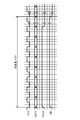
- FIG. 12 is a timing chart when the fixed-length packet shown in FIGS. 10 and 11 is transmitted.
- FIG. 13 is a third example in which a fixed-length packet is formed from a variable-length packet, and a timing chart when it is transmitted.
- FIG. 14 is a timing chart when a plurality of variable-length packets are transmitted with a variable length.
- FIG. 1 is a block diagram of a receiving device including an interface device according to the first embodiment.
- the receiving device 1 is mounted on, for example, a digital television, and can receive signals related to various broadcasting services such as terrestrial digital broadcasting, advanced BS digital broadcasting, and cable television, and communication services using IP packets and the like. is there.
- the receiving device 1 includes an interface device 2 as a front end processing unit and a back end processing unit 3.
- the interface device 2 receives at least one carrier wave such as an I / Q (In-phase / Quadrature-phase) signal or an IF (Intermediate Frequency) signal input from an antenna, and has a variable length with a TS packet from the carrier wave. Packets are extracted, and these packets are sent as data signals DATA to the back-end processing unit 3 in synchronization with the clock signal CLK.
- the carrier wave includes, for example, a signal related to television broadcasting (BS broadcasting, digital terrestrial broadcasting, etc.) and communication.
- the interface device 2 can output the packet clock signal PCLK indicating the head position of the signal DATA and the data enable signal DE indicating the valid period of the signal DATA.
- FIG. 2 is a block diagram of the interface device according to the first embodiment.
- the interface device 2 includes a reception unit 4, a TS packet acquisition unit 5, a variable length packet acquisition unit 6, and a selector 7 as a first selector.
- the receiving unit 4 performs, for example, A / D (Analogue-to-Digital) conversion processing, demodulation processing such as 8PSK (Phase Shift Keying) and 16 APSK (Amplitude Shift and Phase Shift Keying), and LDPC (Low Error correction processing using a Density Parity Check) code, a BCH (Bose-Chaudhuri-Hocquenghem) code, or the like is performed.
- a / D Analogue-to-Digital
- demodulation processing such as 8PSK (Phase Shift Keying) and 16 APSK (Amplitude Shift and Phase Shift Keying)
- LDPC Low Error correction processing using a Density Parity Check
- BCH Bose-Chaudhuri-Hocquenghem
- the receiving unit 4 may perform processes other than those described above as long as it can output necessary signals to the TS packet acquiring unit 5 and the variable length packet acquiring unit 6.
- the receiving unit 4 may include a tuner, and a signal related to broadcasting selected by the tuner by an operation of a remote controller or the like may be input.
- the TS packet acquisition unit 5 acquires and outputs a TS packet having a fixed length from the output of the reception unit 4 based on TMCC (Transmission and Multiplexing Configuration and control) information included in the carrier wave. For example, the TS packet acquisition unit 5 can extract a TS packet corresponding to the instructed TS-ID (TS-Identifier).
- TMCC Transmission and Multiplexing Configuration and control
- the variable length packet acquisition unit 6 acquires and outputs a variable length packet such as a TLV packet or an IP packet having a variable length from the output of the reception unit 4 based on the TMCC information.
- the variable-length packet acquisition unit 6 may be connected to the subsequent stage side of the TS packet acquisition unit 5. Further, for example, the variable length packet acquisition unit 6 may be able to extract a TLV packet corresponding to a TLV-ID (TLV-Identifier) instructed by a remote controller or the like.
- TLV-ID TLV-Identifier
- the TS packet acquisition unit 5 can acquire the TS packet and the variable length packet acquisition unit 6 can acquire the variable length packet from the output of the reception unit 4.
- the selector 7 selectively outputs one of the output of the TS packet acquisition unit 5 and the output of the variable length packet acquisition unit 6. For example, the selector 7 may switch the selection of the TS packet or the variable-length packet according to the tuning of the remote controller, or may switch according to the instruction from the back end processing unit 3. The selector 7 outputs the selected packet as a signal DATA.
- the selector 7 may include a circuit that can generate the signal CLK, the signal PCLK, and the signal DE, and the circuit only needs to be provided inside the interface device 2.
- the selector 7 may switch the selection of the TS packet or the variable length packet at an arbitrary timing. For example, when the input of the selector 7 is multiplexed in a time division manner, the selector 7 may be switched in accordance with the time division multiplexing data.
- FIG. 3 is a timing chart of each signal output from the interface device according to the first embodiment.
- FIG. 3 is a timing chart when the selector 7 selects a variable-length packet, that is, when a variable-length byte signal DATA is serially transmitted.
- the signal DATA which is variable length data such as a TLV packet, is transmitted in synchronization with the signal CLK.
- the signal PCLK may perform a predetermined operation in the vicinity of the head of the signal DATA, for example, becomes active in the first byte of the signal DATA.
- the selector 7 selects the TS packet, the signal DATA which is, for example, 188-byte fixed length data is transmitted in synchronization with the signal CLK.
- the back end processing unit 3 can implement a process for determining the leading position and valid period of the signal DATA, the signal PCLK and the signal DE may be omitted.
- the signal DATA may be transmitted in parallel.
- the selector 7 can select a TS packet having a fixed length, or a TLV packet or an IP packet having a variable length, and output it as a signal DATA. Therefore, in the interface device 2, it is possible to share a terminal for transmitting fixed-length packets and variable-length packets and a signal line for transmitting these packets.
- Non-Patent Document 2 discloses an example in which a total of four signals are used in addition to a data signal and a clock signal in order to transmit a TS packet. Therefore, this technique can be used to transmit the TS packet output from the receiving apparatus shown in FIG.
- TLV packet that is separated from the TS packet and output by the receiving apparatus in FIG. 7 of Patent Document 1 needs to be sent separately to the subsequent stage, but transmission of variable-length packets such as a TLV packet is clearly described in these documents. It has not been.
- TS packets and variable-length packets can be transmitted using the same terminal and signal line, so that a dedicated terminal and signal line for transmitting variable-length packets are not required. . That is, different types of data can be transmitted without increasing the number of terminals and the number of wirings.
- the cost of the interface device 2 can be reduced and the circuit scale can be reduced, and the back-end processing unit 3 does not need to increase the number of terminals.
- variable length packet acquisition unit 6 Next, a configuration example of the variable length packet acquisition unit 6 will be described.
- FIG. 4 is a block diagram illustrating a configuration example of the variable length packet acquisition unit according to the first embodiment.
- the variable length packet acquisition unit 6 includes a TLV packet acquisition unit 9, an IP packet generation unit 10, and a selector 11 as a second selector.
- variable-length packet acquisition unit 6 only needs to output a TLV packet
- the IP packet generation unit 10 and the selector 11 may be omitted.
- the TLV packet acquisition unit 9 can acquire the TLV packet from the output of the reception unit 4 based on the pointer / slot information included in the TMCC information. Further, the TLV packet acquisition unit 9 outputs a TLV packet corresponding to the TLV-ID selected by the remote controller or the like using the TLV-ID included in the TMCC information.
- the pointer / slot information is information indicating the start position of the first packet and the end position of the last packet included in each slot.
- the IP packet generator 10 generates an IP packet based on the header information of the TLV packet. Since the IP packet is transmitted in the TLV format, when the header information of the TLV packet indicates that the TLV packet is an IP packet, the IP packet is generated from the TLV packet. When generating an IP packet, tuning with a remote controller or the like, or protocols such as IGMP (Internet Group Management Protocol) and MLD (Multicast Listener Discovery) may be used.
- IGMP Internet Group Management Protocol
- MLD Multicast Listener Discovery
- IP packet generator 10 may be able to generate a UDP (User Datagram Protocol) packet.
- UDP User Datagram Protocol
- the selector 11 selects one of the outputs of the TLV packet acquisition unit 9 and the IP packet generation unit 10.
- the selector 11 may be switchable by a remote controller or the like.
- variable-length packet acquisition unit 6 By configuring the variable-length packet acquisition unit 6 in this way, it is possible to selectively output different types of packets such as TLV packets and IP packets.
- FIG. 5 is a block diagram illustrating a configuration example of the IP packet generation unit.
- the IP packet generation unit 10 includes, for example, an IP conversion unit 14 and a memory 15.
- the IP conversion unit 14 determines whether the header information of the input TLV packet indicates an IP packet. If the input packet is an IP packet in the TLV format, the IP conversion unit 14 removes the TLV header and converts it into an IP. Generate and output a packet.
- the IP unit 14 determines whether or not the header of the IP packet (IP / UDP header, hereinafter abbreviated as a header) is compressed. Is possible.
- the IP conversion unit 14 may output the TLV packet as it is without performing IP conversion.
- the memory 15 is a buffer and is configured to be capable of burst output of buffered packets. Note that the memory 15 may be provided before the IP unit 14.
- the IP packet generation unit 10 may be configured to be capable of burst output that outputs a buffered packet or stops output. Note that the IP packet generation unit 10 may be capable of continuously outputting packets.
- the IP packet generation unit 10 decompresses the header. Therefore, the transmission rate related to the output of the IP packet generation unit 10 when the header is compressed is It is preferably set to be higher than the case where it is not compressed.
- the transmission rate related to the output of the IP packet generation unit 10 is set to be higher than the transmission rate related to the input.
- FIG. 6 is a diagram for explaining data and transmission rates handled by the IP packet generation unit of FIG. 6A shows a case where the header is not compressed, and FIG. 6B shows a case where the header is compressed.
- FIG. 6 shows an example in which an IP packet in TLV format is input and output after being converted to IP.
- packets TLV1 and TLV2, which are TLV packets are input to the IP unit 14 at a transmission rate A1.
- the IP unit 14 the TLV headers of the packets TLV1 and TLV2 are removed, and packets IP1 and IP2, which are IP packets, are generated from each, and output at the transmission rate A2.
- Packets IP1 and IP2 are buffered in the memory 15, and burst output from the IP packet generator 10 at the transmission rate A3.
- packets TLV1 and TLV2 which are TLV packets are input to the IP unit 14 at the transmission rate B1.
- the TLV headers of the packets TLV1 and TLV2 are removed and the respective headers are expanded to generate IP packets IP1 and IP2, which are output at the transmission rate B2.
- Packets IP1 and IP2 are buffered in the memory 15, and burst output from the IP packet generator 10 at the transmission rate B3.
- the size of the packets IP1 and IP2 shown in FIG. 6B is larger than the size of the packets IP1 and IP2 shown in FIG. Also grows.
- the transmission rate B3 related to the output can be switched to be higher than the transmission rate B1 related to the input.
- the transmission rate B3 related to the output of the IP packet generation unit 10 when the header is compressed is higher than the transmission rate A3 related to the output of the IP packet generation unit 10 when the header is not compressed. It may be switchable.
- the transmission rates in the IP packet generation unit 10 are different so that the transmission rate A3 ⁇ transmission rate B3 or the transmission rate B1 ⁇ transmission rate B3.
- the transmission rate A3 may be matched with the transmission rate B3. In this case, it is not necessary to switch the transmission rate regardless of whether the header is compressed, and packets can be sent at a high transmission rate.
- FIG. 7 is another diagram for explaining the data and transmission rate handled by the IP packet generation unit of FIG. 7A shows a case where a TLV packet is output, and FIG. 7B shows a case where an IP packet is output. In FIG. 7B, it is assumed that the header is compressed.
- the packets TLV1 and TLV2 input to the IP conversion unit 14 are buffered in the memory 15, and the packet TLV1 is transmitted at the transmission rate A3.
- TLV2 is burst output.
- the IP conversion unit 14 removes the TLV headers of the packets TLV1 and TLV2 and expands the respective headers so that the packets IP1 and IP2 Are output at the transmission rate B2.
- Packets IP1 and IP2 are buffered in the memory 15, and burst output from the IP packet generator 10 at the transmission rate B3. At this time, it is sufficient that the transmission rate B1 ⁇ the transmission rate B3.
- FIG. 7A shows a case where a TLV packet is output, but the transmission rates A1 to A3 are set to be the same as the transmission rates B1 to B3 shown in FIG. 7B. Also good.
- GSE Generic Stream Encapsulated
- FIG. 8 is a block diagram of an interface device according to a modification of the first embodiment. In FIG. 8, differences from FIG. 2 will be mainly described.
- the reception unit 4 includes a first reception processing unit 4a and a second reception processing unit 4b.
- the reception processing unit 4a receives, for example, a first carrier wave related to terrestrial digital broadcasting, performs A / D conversion processing, demodulation processing, error correction processing, and the like, and converts it into a format necessary for processing in the TS packet acquisition unit 5. Output.
- the reception processing unit 4b receives, for example, a second carrier wave related to BS digital broadcasting, performs A / D conversion processing, demodulation processing, correction processing, and the like, and converts it into a format necessary for processing by the variable-length packet acquisition unit 6. Output.
- the receiving unit 4 receives a plurality of different carrier waves, performs the above-described processing on each carrier wave, and can output each processed signal to the TS packet acquisition unit 5 and the variable length packet acquisition unit 6, respectively. It may be configured.
- the selector 7 can selectively output variable-length packets such as TS packets or TLV packets, so that different types of packets can be transmitted through common terminals and signal lines.
- FIG. 9 is a block diagram of a receiving device including the interface device according to the second embodiment. In the present embodiment, differences from the first embodiment will be mainly described.
- the interface device 2 includes a reception unit 4, a TS packet acquisition unit 5, a variable length packet acquisition unit 6, a selector 7, and a packet adjustment unit 12.
- the packet adjustment unit 12 can adjust the size of a variable-length packet such as a TLV packet output from the variable-length packet acquisition unit 6 to be the same size as the TS packet. Therefore, when the size of the TS packet is, for example, 188 bytes, the packet adjustment unit 12 adjusts the size of the variable length packet to be 188 bytes. That is, the packet adjustment unit 12 can handle the variable length packet as a pseudo fixed length packet.
- the selector 7 selects and outputs one of the outputs of the TS packet acquisition unit 5, the variable length packet acquisition unit 6, and the packet adjustment unit 12.
- the packet adjustment unit 12 and the variable-length packet acquisition unit 6 may be integrated.
- the selector 7 selects and outputs either the TS packet acquisition unit 5 or the output of the circuit formed integrally therewith. Good.
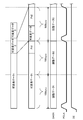
- FIG. 10 is a diagram for explaining a first example in which a fixed-length packet is formed from a variable-length packet.
- variable-length data 1 to variable-length data 4 that are variable-length packets having different sizes are adjusted to become adjustment data 1 to adjustment data 3 that are fixed-length data of, for example, 188 bytes. .
- variable length data 1 is longer than 188 bytes
- a part of the variable length data 1 is divided by 188 bytes to form the adjustment data 1.
- the adjustment data 2 is formed from the remaining data of the variable length data 1 and data obtained by dividing a part of the variable length data 2.
- the adjustment data 3 is formed from the remaining data of the variable length data 2, the variable length data 3, and the data obtained by dividing a part of the variable length data 4.
- the size of the variable length data is adjusted, and adjustment data having a fixed size is formed.
- FIG. 11 is a diagram for explaining a second example in which a fixed-length packet is formed from a variable-length packet.
- a TLV-ID included in a TMCC signal multiplexed and transmitted in advanced BS digital broadcasting will be described.
- variable length data 1 and variable length data 3 are selected by TLV-ID among variable length data 1 to variable length data 4 which are variable length packets.
- the unselected variable length data 2 and variable length data 4 are NULL.
- the process of making the non-selected variable length data 2 and variable length data 4 NULL may be performed by the variable length packet acquisition unit 6 or its preceding block, or may be performed by the packet adjustment unit 12. .
- the adjustment data 2 is formed from the remaining data of the variable length data 1 and the data obtained by dividing a part of the NULL data.
- the adjustment data 3 is formed from the remaining data of the NULL data, the variable length data 3, and the data obtained by dividing a part of the NULL data.
- the non-selected variable-length data may be replaced with arbitrary data such as 0xFF, for example, as predetermined data instead of simple NULL data.
- the NULL data may have a header part that the variable-length data has in common, and the NULL data may have a format in which the size of the NULL data is known.
- adjustment data is formed from an IP packet as a variable-length packet.
- non-selected variable-length data is replaced with NULL data, but non-selected variable-length data may be removed. That is, in the state immediately before the adjustment shown in FIG. 11, the variable length data 1 may be followed by the variable length data 3 instead of the NULL data.
- FIG. 12 is a timing chart when the fixed-length packet shown in FIGS. 10 and 11 is transmitted.
- variable-length packets are sent in units of 188 bytes, for example, variable-length packets can be sent in the same format as TS packets that are fixed-length data.
- variable-length packets can be handled as fixed-length data.
- the signal PCLK and the signal DE may be omitted. Further, the signal PCLK may become active every the same size (for example, 188 bytes) as the TS packet. Alternatively, the signal PCLK may become active at the head position of the variable length data before the size is adjusted.
- FIG. 13 is a third example in which a fixed-length packet is formed from variable-length packets and a timing chart in the case of sending it. Note that the signal CLK is omitted.
- FIG. 13 shows an example in which the size of the variable-length packet is adjusted to be an integral multiple of the fixed-length packet.
- variable length data 1 which is a variable length packet is divided into fixed length data 1 of 188 bytes and data of less than 188 bytes. At this time, the data of less than 188 bytes is dummy data. Data Pd1 is added.
- the adjustment data 1 is formed from the data of the first 188 bytes of the variable length data 1
- the adjustment data 2 is formed by adding the data Pd1 to the remaining variable length data 1 until the size becomes 188 bytes.
- variable length data 2 is less than 188 bytes
- data Pd2 which is dummy data is added to the variable length data 2 until the size becomes 188 bytes. That is, the adjustment data 3 is formed from the variable length data 2 and the data Pd2.
- the signal PCLK that becomes active at the head position of the variable length data 1 to variable length data 3 that is the data before the size is adjusted is used.
- the transmission rate on the output side is set higher than the transmission rate on the input side to prevent overflow. May be.
- the dummy data is added to the end of the variable length data, but may be added to the top of the variable length data. That is, it is only necessary that the size of the variable-length data becomes the same as the size of the TS packet by adding dummy data.
- the packet adjustment unit 12 adjusts the size of the variable length packet to form fixed length data having the same size as the TS packet.
- the variable length packet input to the packet adjustment unit 12 may include predetermined dummy data.
- the signal PCLK becomes active at the head position of the variable length data 1 to variable length data 3. That is, the signal PCLK is a signal indicating the head position of the data, but may be active at the head position of the adjustment data corresponding to the head position of the variable length data.
- the back-end processing unit 3 can receive the variable-length packet as fixed-length data, and determines the actual start position of the received data (that is, the start position of the variable-length packet) based on the signal PCLK. Judgment can be made.
- variable-length packet As described above, by changing the variable-length packet to a pseudo-fixed-length packet, it is possible to reduce changes in processing content, transmission protocol, and the like in the back-end processing unit 3.
- variable length packet is sent as it is.
- the back-end processing unit 3 needs to specify the boundary between the variable-length packets by calculating the head position and size of the packet from the packet header information. At this time, if the header information cannot be analyzed for some reason (such as garbled data), the back-end processing unit 3 may not be able to perform normal processing.
- the interface device 2 should transmit a signal DATA as shown in FIG. Good.
- FIG. 14 is a timing chart when a plurality of variable-length packets are transmitted with a variable length. Note that the signal CLK is omitted.
- a signal PCLK that becomes active at each head position of variable length data 1 to variable length data 3 which is a variable length packet is sent together with variable length data 1 to variable length data 3.
- the back-end processing unit 3 can accurately recognize the head positions of the variable length data 1 to the variable length data 3 based on the signal PCLK. Therefore, in the back-end processing unit 3, for example, software processing by a CPU (Central Processing Unit) may be implemented so as to specify variable length data based on the signal PCLK.
- a CPU Central Processing Unit
- the interface device can transmit a plurality of different types of signals without increasing the number of terminals and the number of wires, and thus is useful for reducing the circuit scale and cost of the receiving device.
Landscapes
- Engineering & Computer Science (AREA)
- Signal Processing (AREA)
- Computer Networks & Wireless Communication (AREA)
- Multimedia (AREA)
- Computer Security & Cryptography (AREA)
- Quality & Reliability (AREA)
- Data Exchanges In Wide-Area Networks (AREA)
- Two-Way Televisions, Distribution Of Moving Picture Or The Like (AREA)
- Communication Control (AREA)
- Time-Division Multiplex Systems (AREA)
Abstract
L'invention concerne un dispositif d'interface (2) qui permet d'envoyer un signal de données (DATA) en synchronisation avec un signal d'horloge (CLK). Le dispositif comprend : une unité de réception (4) qui soumet une porteuse d'entrée à un processus de démodulation et à un processus de correction d'erreur et qui produit en sortie un signal soumis à ces processus; une unité d'acquisition de paquets TS (5) qui acquiert un paquet TS inclus dans la sortie produite par l'unité de réception; une unité (6) d'acquisition de paquets de longueur variable qui acquiert un paquet de longueur variable inclus dans la sortie produite par l'unité de réception; et un premier sélecteur (7) qui sélectionne soit le paquet TS, soit le paquet de longueur variable et qui produit en sortie le paquet sélectionné en tant que signal de données.
Priority Applications (4)
| Application Number | Priority Date | Filing Date | Title |
|---|---|---|---|
| JP2016529017A JP6674105B2 (ja) | 2014-06-24 | 2015-06-10 | インタフェース装置およびそれを備えた受信装置 |
| CN201580033773.2A CN106471761B (zh) | 2014-06-24 | 2015-06-10 | 接口装置及具备该接口装置的接收装置 |
| US15/388,294 US10715642B2 (en) | 2014-06-24 | 2016-12-22 | Interface device and receiver including the same |
| US16/896,490 US11212376B2 (en) | 2014-06-24 | 2020-06-09 | Method of transmitting a data signal in sync with a clock signal |
Applications Claiming Priority (2)
| Application Number | Priority Date | Filing Date | Title |
|---|---|---|---|
| JP2014128919 | 2014-06-24 | ||
| JP2014-128919 | 2014-06-24 |
Related Child Applications (1)
| Application Number | Title | Priority Date | Filing Date |
|---|---|---|---|
| US15/388,294 Continuation US10715642B2 (en) | 2014-06-24 | 2016-12-22 | Interface device and receiver including the same |
Publications (1)
| Publication Number | Publication Date |
|---|---|
| WO2015198545A1 true WO2015198545A1 (fr) | 2015-12-30 |
Family
ID=54937656
Family Applications (1)
| Application Number | Title | Priority Date | Filing Date |
|---|---|---|---|
| PCT/JP2015/002896 Ceased WO2015198545A1 (fr) | 2014-06-24 | 2015-06-10 | Dispositif d'interface et dispositif de réception le comprenant |
Country Status (4)
| Country | Link |
|---|---|
| US (2) | US10715642B2 (fr) |
| JP (2) | JP6674105B2 (fr) |
| CN (2) | CN110071785B (fr) |
| WO (1) | WO2015198545A1 (fr) |
Cited By (3)
| Publication number | Priority date | Publication date | Assignee | Title |
|---|---|---|---|---|
| WO2016199603A1 (fr) * | 2015-06-11 | 2016-12-15 | ソニー株式会社 | Dispositif de traitement de signal, procédé de traitement de signal, et programme |
| WO2018230348A1 (fr) * | 2017-06-14 | 2018-12-20 | ソニーセミコンダクタソリューションズ株式会社 | Dispositif de démodulation, dispositif de traitement, dispositif de réception et procédé de traitement de données |
| WO2021153297A1 (fr) * | 2020-01-28 | 2021-08-05 | ソニーセミコンダクタソリューションズ株式会社 | Dispositif de traitement d'informations, procédé de traitement d'informations et programme |
Families Citing this family (7)
| Publication number | Priority date | Publication date | Assignee | Title |
|---|---|---|---|---|
| JP6706784B2 (ja) * | 2014-09-12 | 2020-06-10 | パナソニックIpマネジメント株式会社 | 送信装置、受信装置、送信方法及び受信方法 |
| JP6300116B2 (ja) * | 2014-10-10 | 2018-03-28 | パナソニックIpマネジメント株式会社 | 送信方法、送信装置及びシステム |
| JP6290852B2 (ja) * | 2015-12-24 | 2018-03-07 | 日本電気株式会社 | 信号構成装置、信号構成システム、信号構成方法、および信号構成用プログラム |
| JP7017029B2 (ja) * | 2017-05-08 | 2022-02-08 | ソニーグループ株式会社 | 送信装置、及び送信方法 |
| WO2019142416A1 (fr) * | 2018-01-18 | 2019-07-25 | ソニーセミコンダクタソリューションズ株式会社 | Dispositif de traitement du signal, et procédé de traitement du signal |
| JP2020141256A (ja) * | 2019-02-28 | 2020-09-03 | ソニーセミコンダクタソリューションズ株式会社 | 復調回路、復調方法、送信装置 |
| US12015822B2 (en) * | 2020-02-26 | 2024-06-18 | Panasonic Intellectual Property Management Co., Ltd. | Video signal processing device, video signal processing method, recording medium, and signal processing circuit |
Citations (3)
| Publication number | Priority date | Publication date | Assignee | Title |
|---|---|---|---|---|
| JPH08181715A (ja) * | 1994-12-27 | 1996-07-12 | Matsushita Electric Works Ltd | 送受信装置 |
| WO2013011545A1 (fr) * | 2011-07-15 | 2013-01-24 | 三菱電機株式会社 | Appareil de transmission, appareil de réception, appareil de communication, système de communication et procédé de transmission |
| JP2013175949A (ja) * | 2012-02-24 | 2013-09-05 | Nippon Hoso Kyokai <Nhk> | 送信装置及び受信装置 |
Family Cites Families (33)
| Publication number | Priority date | Publication date | Assignee | Title |
|---|---|---|---|---|
| CA2360444C (fr) * | 1999-11-17 | 2007-01-16 | Sony Corporation | Procede et appareil pour le traitement de signaux numeriques |
| IL133896A0 (en) * | 2000-01-06 | 2001-04-30 | Telescicom Ltd | Method and system for encoding data for transmission channels |
| KR100749070B1 (ko) * | 2000-07-14 | 2007-08-13 | 삼성전자주식회사 | 트랜스포트스트림을 역다중화하는 장치 |
| CN1669320B (zh) * | 2002-07-16 | 2011-03-23 | 松下电器产业株式会社 | 内容接收器 |
| US7610427B2 (en) * | 2003-05-22 | 2009-10-27 | Panasonic Corporation | Functional module card for transferring digital broadcasting signal using a clock generated based on a synchronous signal extracted from a received data signal |
| US20050120374A1 (en) * | 2003-12-01 | 2005-06-02 | General Instrument Corporation | Methods and apparatus for passing an on-screen display over a serial interface |
| CN100586100C (zh) * | 2003-12-11 | 2010-01-27 | 松下电器产业株式会社 | 包发送装置 |
| JP2005260728A (ja) * | 2004-03-12 | 2005-09-22 | Ntt Docomo Inc | 移動端末、視聴情報収集システム、及び視聴情報収集方法 |
| US20060034273A1 (en) * | 2004-07-22 | 2006-02-16 | Matsushita Electric Industrial Co., Ltd. | Transport stream processing apparatus |
| JP2006311027A (ja) * | 2005-04-27 | 2006-11-09 | Victor Co Of Japan Ltd | デジタル放送受信装置及びデジタル放送受信方法 |
| US7929696B2 (en) * | 2005-06-07 | 2011-04-19 | Sony Corporation | Receiving DBS content on digital TV receivers |
| WO2007148863A1 (fr) * | 2006-06-20 | 2007-12-27 | Lg Electronics Inc. | Système de diffusion numérique et procédé de traitement de données |
| CN101517903B (zh) * | 2006-10-04 | 2012-05-09 | 三菱电机株式会社 | 多媒体信息接收装置 |
| JP5114084B2 (ja) * | 2007-04-04 | 2013-01-09 | 株式会社日立製作所 | 移動体放送受信端末および移動体放送受信方法 |
| US8817780B2 (en) * | 2007-08-08 | 2014-08-26 | Maxlinear, Inc. | TS packet grooming |
| JP5252952B2 (ja) * | 2008-03-11 | 2013-07-31 | キヤノン株式会社 | 受信装置 |
| JP5541488B2 (ja) | 2009-02-09 | 2014-07-09 | ソニー株式会社 | コンテンツ受信装置および方法 |
| CN101521809B (zh) * | 2009-03-26 | 2012-01-04 | 上海交通大学 | 数字电视单频网可变长同步信息分布式传输方法 |
| JP5400575B2 (ja) * | 2009-11-11 | 2014-01-29 | 日本放送協会 | 可変長パケットの送信装置、受信装置及びプログラム |
| CN101742249B (zh) * | 2009-12-18 | 2012-05-30 | 四川长虹电器股份有限公司 | 一种可信双向网络数字电视系统的实现方法 |
| US9003455B2 (en) * | 2010-07-30 | 2015-04-07 | Guest Tek Interactive Entertainment Ltd. | Hospitality media system employing virtual set top boxes |
| KR101670723B1 (ko) * | 2011-01-04 | 2016-11-01 | 삼성전자주식회사 | 비디오 및 오디오 통신 시스템에서 가변 길이의 전송 패킷 지원 방법 및 장치 |
| CN102769799A (zh) * | 2011-05-03 | 2012-11-07 | 朱佩江 | 一种在ip网络中实现数字电视业务分发服务的方法及系统 |
| JP5689365B2 (ja) * | 2011-05-27 | 2015-03-25 | 富士通株式会社 | 復調回路、復調方法および受信装置 |
| US9124396B2 (en) * | 2011-07-28 | 2015-09-01 | Allen LeRoy Limberg | COFDM digital television receivers for iterative-diversity reception |
| CN102281223B (zh) * | 2011-08-04 | 2014-06-11 | 联思普瑞(武汉)电子科技有限公司 | 全数字最小频移键控电力载波装置 |
| JP6032945B2 (ja) * | 2012-05-28 | 2016-11-30 | サターン ライセンシング エルエルシーSaturn Licensing LLC | 信号処理装置、及び、信号処理方法 |
| CN103517330B (zh) * | 2012-06-15 | 2018-08-10 | 南京中兴新软件有限责任公司 | 一种鲁棒性头压缩报文的发送方法及装置 |
| CN202696813U (zh) * | 2012-08-10 | 2013-01-23 | 王涛 | 基于多节目传输流转多路单节目传输流的ip输出装置 |
| US20140086407A1 (en) * | 2012-09-25 | 2014-03-27 | General Instrument Corporation | Conditional Access to Encrypted Media Content |
| WO2014061488A1 (fr) * | 2012-10-17 | 2014-04-24 | ソニー株式会社 | Dispositif de traitement de données, procédé de traitement de données et programme |
| JP6382029B2 (ja) * | 2013-09-20 | 2018-08-29 | パナソニック インテレクチュアル プロパティ コーポレーション オブ アメリカPanasonic Intellectual Property Corporation of America | 送信方法、受信方法、送信装置、及び受信装置 |
| CN103763630A (zh) * | 2014-01-23 | 2014-04-30 | 深圳市同洲电子股份有限公司 | 一种网关设备以及协议转换的方法 |
-
2015
- 2015-06-10 WO PCT/JP2015/002896 patent/WO2015198545A1/fr not_active Ceased
- 2015-06-10 CN CN201910342822.0A patent/CN110071785B/zh active Active
- 2015-06-10 JP JP2016529017A patent/JP6674105B2/ja active Active
- 2015-06-10 CN CN201580033773.2A patent/CN106471761B/zh active Active
-
2016
- 2016-12-22 US US15/388,294 patent/US10715642B2/en active Active
-
2020
- 2020-03-03 JP JP2020035556A patent/JP6823277B2/ja active Active
- 2020-06-09 US US16/896,490 patent/US11212376B2/en active Active
Patent Citations (3)
| Publication number | Priority date | Publication date | Assignee | Title |
|---|---|---|---|---|
| JPH08181715A (ja) * | 1994-12-27 | 1996-07-12 | Matsushita Electric Works Ltd | 送受信装置 |
| WO2013011545A1 (fr) * | 2011-07-15 | 2013-01-24 | 三菱電機株式会社 | Appareil de transmission, appareil de réception, appareil de communication, système de communication et procédé de transmission |
| JP2013175949A (ja) * | 2012-02-24 | 2013-09-05 | Nippon Hoso Kyokai <Nhk> | 送信装置及び受信装置 |
Cited By (10)
| Publication number | Priority date | Publication date | Assignee | Title |
|---|---|---|---|---|
| WO2016199603A1 (fr) * | 2015-06-11 | 2016-12-15 | ソニー株式会社 | Dispositif de traitement de signal, procédé de traitement de signal, et programme |
| JPWO2016199603A1 (ja) * | 2015-06-11 | 2018-03-29 | ソニー株式会社 | 信号処理装置および信号処理方法、並びにプログラム |
| US10644864B2 (en) | 2015-06-11 | 2020-05-05 | Sony Corporation | Signal processing device and method to enable transmission of type length value (TLV) packets |
| WO2018230348A1 (fr) * | 2017-06-14 | 2018-12-20 | ソニーセミコンダクタソリューションズ株式会社 | Dispositif de démodulation, dispositif de traitement, dispositif de réception et procédé de traitement de données |
| JPWO2018230348A1 (ja) * | 2017-06-14 | 2020-04-16 | ソニーセミコンダクタソリューションズ株式会社 | 復調装置、処理装置、受信装置、及びデータ処理方法 |
| US11368748B2 (en) | 2017-06-14 | 2022-06-21 | Sony Semiconductor Solutions Corporation | Demodulation device, processing device, reception device, and data processing method |
| JP7191822B2 (ja) | 2017-06-14 | 2022-12-19 | ソニーセミコンダクタソリューションズ株式会社 | 復調装置、処理装置、受信装置、及びデータ処理方法 |
| US11653058B2 (en) | 2017-06-14 | 2023-05-16 | Sony Semiconductor Solutions Corporation | Demodulation device, processing device, reception device, and data processing method |
| WO2021153297A1 (fr) * | 2020-01-28 | 2021-08-05 | ソニーセミコンダクタソリューションズ株式会社 | Dispositif de traitement d'informations, procédé de traitement d'informations et programme |
| US11917236B2 (en) | 2020-01-28 | 2024-02-27 | Sony Semiconductor Solutions Corporation | Information processing apparatus, information processing method, and non-transitory computer-readable media that add additional information to baseband packet |
Also Published As
| Publication number | Publication date |
|---|---|
| JP6823277B2 (ja) | 2021-02-03 |
| US10715642B2 (en) | 2020-07-14 |
| CN110071785A (zh) | 2019-07-30 |
| US20200304612A1 (en) | 2020-09-24 |
| CN106471761B (zh) | 2019-05-21 |
| US11212376B2 (en) | 2021-12-28 |
| US20170118317A1 (en) | 2017-04-27 |
| JPWO2015198545A1 (ja) | 2017-06-01 |
| CN110071785B (zh) | 2021-10-26 |
| CN106471761A (zh) | 2017-03-01 |
| JP6674105B2 (ja) | 2020-04-01 |
| JP2020102862A (ja) | 2020-07-02 |
Similar Documents
| Publication | Publication Date | Title |
|---|---|---|
| JP6823277B2 (ja) | インタフェース方法 | |
| EP3022881B1 (fr) | Appareil d'émission, appareil de réception, et procédé de traitement de signal de ceux-ci | |
| US20060133429A1 (en) | Device and method for demultiplexing received transport stream in digital broadcasting receiver | |
| US10097673B2 (en) | Method and system for serialization and deserialization (SERDES) for inter-system communications | |
| JP7397916B2 (ja) | 受信方法および端末 | |
| KR100424496B1 (ko) | 디지털 vsb시스템의 동기신호를 이용한 이퀄라이져 제어 방법 및 장치 | |
| JP4199436B2 (ja) | ディジタル信号受信装置、及びディジタル信号受信システム | |
| US11784736B2 (en) | Digital broadcast receiver and digital broadcast receiver system | |
| US20120151296A1 (en) | Data processing device and data processing method | |
| JP4978750B2 (ja) | 受信装置及び受信システム | |
| KR100661253B1 (ko) | 수신장치 및 수신 복호방법 | |
| JP4509824B2 (ja) | ダイバーシチ方式受信装置及びダイバーシチ方式受信装置の受信信号位相制御方法 | |
| US12015822B2 (en) | Video signal processing device, video signal processing method, recording medium, and signal processing circuit | |
| JP4839385B2 (ja) | データ受信装置 | |
| KR100525848B1 (ko) | 아날로그 방송을 위한 연주소-송신소 링크(stl)를이용한 디지털 tv 송신기의 단일 주파수 네트워크 시스템 | |
| JP2025109224A (ja) | 緊急情報付与装置および緊急情報付与方法 | |
| JP2009005307A (ja) | デジタル受信装置およびデジタル受信方法 | |
| JP2004120275A (ja) | ディジタル放送受信機 | |
| WO2018021036A1 (fr) | Dispositif de réception, procédé de réception et programme | |
| JP2001128162A (ja) | 復号装置及び復号方法 |
Legal Events
| Date | Code | Title | Description |
|---|---|---|---|
| 121 | Ep: the epo has been informed by wipo that ep was designated in this application |
Ref document number: 15811822 Country of ref document: EP Kind code of ref document: A1 |
|
| ENP | Entry into the national phase |
Ref document number: 2016529017 Country of ref document: JP Kind code of ref document: A |
|
| NENP | Non-entry into the national phase |
Ref country code: DE |
|
| 122 | Ep: pct application non-entry in european phase |
Ref document number: 15811822 Country of ref document: EP Kind code of ref document: A1 |