WO2015198578A1 - 投影システム - Google Patents
投影システム Download PDFInfo
- Publication number
- WO2015198578A1 WO2015198578A1 PCT/JP2015/003101 JP2015003101W WO2015198578A1 WO 2015198578 A1 WO2015198578 A1 WO 2015198578A1 JP 2015003101 W JP2015003101 W JP 2015003101W WO 2015198578 A1 WO2015198578 A1 WO 2015198578A1
- Authority
- WO
- WIPO (PCT)
- Prior art keywords
- light
- projection
- image
- infrared
- control device
- Prior art date
- Legal status (The legal status is an assumption and is not a legal conclusion. Google has not performed a legal analysis and makes no representation as to the accuracy of the status listed.)
- Ceased
Links
Images


Classifications
-
- A—HUMAN NECESSITIES
- A61—MEDICAL OR VETERINARY SCIENCE; HYGIENE
- A61B—DIAGNOSIS; SURGERY; IDENTIFICATION
- A61B90/00—Instruments, implements or accessories specially adapted for surgery or diagnosis and not covered by any of the groups A61B1/00 - A61B50/00, e.g. for luxation treatment or for protecting wound edges
- A61B90/36—Image-producing devices or illumination devices not otherwise provided for
-
- A—HUMAN NECESSITIES
- A61—MEDICAL OR VETERINARY SCIENCE; HYGIENE
- A61B—DIAGNOSIS; SURGERY; IDENTIFICATION
- A61B10/00—Instruments for taking body samples for diagnostic purposes; Other methods or instruments for diagnosis, e.g. for vaccination diagnosis, sex determination or ovulation-period determination; Throat striking implements
-
- A—HUMAN NECESSITIES
- A61—MEDICAL OR VETERINARY SCIENCE; HYGIENE
- A61B—DIAGNOSIS; SURGERY; IDENTIFICATION
- A61B5/00—Measuring for diagnostic purposes; Identification of persons
- A61B5/0059—Measuring for diagnostic purposes; Identification of persons using light, e.g. diagnosis by transillumination, diascopy, fluorescence
- A61B5/0071—Measuring for diagnostic purposes; Identification of persons using light, e.g. diagnosis by transillumination, diascopy, fluorescence by measuring fluorescence emission
-
- A—HUMAN NECESSITIES
- A61—MEDICAL OR VETERINARY SCIENCE; HYGIENE
- A61B—DIAGNOSIS; SURGERY; IDENTIFICATION
- A61B90/00—Instruments, implements or accessories specially adapted for surgery or diagnosis and not covered by any of the groups A61B1/00 - A61B50/00, e.g. for luxation treatment or for protecting wound edges
-
- H—ELECTRICITY
- H04—ELECTRIC COMMUNICATION TECHNIQUE
- H04N—PICTORIAL COMMUNICATION, e.g. TELEVISION
- H04N23/00—Cameras or camera modules comprising electronic image sensors; Control thereof
- H04N23/20—Cameras or camera modules comprising electronic image sensors; Control thereof for generating image signals from infrared radiation only
-
- H—ELECTRICITY
- H04—ELECTRIC COMMUNICATION TECHNIQUE
- H04N—PICTORIAL COMMUNICATION, e.g. TELEVISION
- H04N23/00—Cameras or camera modules comprising electronic image sensors; Control thereof
- H04N23/56—Cameras or camera modules comprising electronic image sensors; Control thereof provided with illuminating means
-
- H—ELECTRICITY
- H04—ELECTRIC COMMUNICATION TECHNIQUE
- H04N—PICTORIAL COMMUNICATION, e.g. TELEVISION
- H04N7/00—Television systems
- H04N7/18—Closed-circuit television [CCTV] systems, i.e. systems in which the video signal is not broadcast
- H04N7/183—Closed-circuit television [CCTV] systems, i.e. systems in which the video signal is not broadcast for receiving images from a single remote source
-
- A—HUMAN NECESSITIES
- A61—MEDICAL OR VETERINARY SCIENCE; HYGIENE
- A61B—DIAGNOSIS; SURGERY; IDENTIFICATION
- A61B90/00—Instruments, implements or accessories specially adapted for surgery or diagnosis and not covered by any of the groups A61B1/00 - A61B50/00, e.g. for luxation treatment or for protecting wound edges
- A61B90/36—Image-producing devices or illumination devices not otherwise provided for
- A61B2090/364—Correlation of different images or relation of image positions in respect to the body
- A61B2090/366—Correlation of different images or relation of image positions in respect to the body using projection of images directly onto the body
-
- A—HUMAN NECESSITIES
- A61—MEDICAL OR VETERINARY SCIENCE; HYGIENE
- A61B—DIAGNOSIS; SURGERY; IDENTIFICATION
- A61B90/00—Instruments, implements or accessories specially adapted for surgery or diagnosis and not covered by any of the groups A61B1/00 - A61B50/00, e.g. for luxation treatment or for protecting wound edges
- A61B90/30—Devices for illuminating a surgical field, the devices having an interrelation with other surgical devices or with a surgical procedure
-
- A—HUMAN NECESSITIES
- A61—MEDICAL OR VETERINARY SCIENCE; HYGIENE
- A61B—DIAGNOSIS; SURGERY; IDENTIFICATION
- A61B90/00—Instruments, implements or accessories specially adapted for surgery or diagnosis and not covered by any of the groups A61B1/00 - A61B50/00, e.g. for luxation treatment or for protecting wound edges
- A61B90/36—Image-producing devices or illumination devices not otherwise provided for
- A61B90/361—Image-producing devices, e.g. surgical cameras
-
- G—PHYSICS
- G03—PHOTOGRAPHY; CINEMATOGRAPHY; ANALOGOUS TECHNIQUES USING WAVES OTHER THAN OPTICAL WAVES; ELECTROGRAPHY; HOLOGRAPHY
- G03B—APPARATUS OR ARRANGEMENTS FOR TAKING PHOTOGRAPHS OR FOR PROJECTING OR VIEWING THEM; APPARATUS OR ARRANGEMENTS EMPLOYING ANALOGOUS TECHNIQUES USING WAVES OTHER THAN OPTICAL WAVES; ACCESSORIES THEREFOR
- G03B15/00—Special procedures for taking photographs; Apparatus therefor
- G03B15/14—Special procedures for taking photographs; Apparatus therefor for taking photographs during medical operations
-
- G—PHYSICS
- G03—PHOTOGRAPHY; CINEMATOGRAPHY; ANALOGOUS TECHNIQUES USING WAVES OTHER THAN OPTICAL WAVES; ELECTROGRAPHY; HOLOGRAPHY
- G03B—APPARATUS OR ARRANGEMENTS FOR TAKING PHOTOGRAPHS OR FOR PROJECTING OR VIEWING THEM; APPARATUS OR ARRANGEMENTS EMPLOYING ANALOGOUS TECHNIQUES USING WAVES OTHER THAN OPTICAL WAVES; ACCESSORIES THEREFOR
- G03B17/00—Details of cameras or camera bodies; Accessories therefor
- G03B17/48—Details of cameras or camera bodies; Accessories therefor adapted for combination with other photographic or optical apparatus
- G03B17/54—Details of cameras or camera bodies; Accessories therefor adapted for combination with other photographic or optical apparatus with projector
Definitions
- the present disclosure relates to a projection system that projects an image onto a subject.
- Patent Document 1 discloses a surgical operation support system in which image data indicating a diseased part of a living body undergoing surgery is output from a fluorescent image capturing device, an image based on the image data is reproduced by an image projection device, and displayed on the actual diseased part.
- a substance that fluoresces when irradiated with light of a predetermined wavelength is preliminarily administered to an affected part of a living body. That is, this system supports confirmation of a lesioned part by displaying a fluorescent image in which the affected part fluoresces on an actual affected part.
- the present disclosure relates to an imaging unit that captures a specific area of a subject specified by light excited by light of a predetermined wavelength, a projection unit that projects an image of the specific area with visible light, and an image of the specific area
- a projection system includes a control unit that controls to project incidental information accompanying an image of a region onto a subject, and an optical unit that matches an optical path of an imaging unit with respect to the subject and an optical path of the projection unit with respect to the subject.
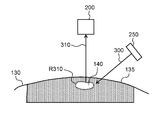
- FIG. 1 is a schematic diagram showing the configuration of the surgery support system 100.
- FIG. 2A is a diagram illustrating a state of the surgical field in the surgery support system 100 before performing the projection operation.
- FIG. 2B is a diagram illustrating a state in which a projection operation is performed on the surgical field of FIG. 2A.
- FIG. 3 is a schematic diagram showing a configuration of the deviation adjustment system 500.
- FIG. 4A is a perspective view illustrating an appearance of the light adjustment device 400.
- FIG. FIG. 4B is an exploded perspective view showing the configuration of the light adjustment device 400.
- FIG. 5A is a perspective view of the light adjustment device 400 during adjustment of misalignment.
- FIG. 5B is a diagram illustrating an example of the state of the projection surface 402 when the deviation is not adjusted.
- FIG. 5C is a diagram showing an image for projection in the example of FIG. 5B.
- FIG. 5D is a diagram illustrating a projection image obtained by adjusting the shift of the image in FIG. 5C.
- FIG. 5E is a diagram illustrating an example of a state of the projection surface 402 after the shift adjustment.
- FIG. 6 is a diagram illustrating a state of the projection surface 402 in the usage example of the light adjustment device 400.
- FIG. 7A is a plan view of an aperture mask 430 'in the application example.
- FIG. 7B is a diagram showing a state projected on the projection surface using the aperture mask 430 ′ of FIG. 7A.
- FIG. 7C is a diagram illustrating a state where the projection operation of the surgery support system 100 is performed on the projection plane of FIG.
- FIG. 8A is a diagram for explaining infrared fluorescence 310 and visible laser light 320 before deviation adjustment.
- FIG. 8B is a diagram for explaining the infrared fluorescence 310 and the visible laser light 320 after the deviation adjustment.
- FIG. 9 is a diagram for explaining a scanning pattern of the projection unit 220.
- FIG. 10 is a flowchart showing the cutting operation of the auxiliary cutting line according to the detection of the affected part.
- FIG. 11A is a diagram for explaining the projection operation of the auxiliary cutting line in the first cutting margin width.
- FIG. 11B is a diagram for explaining the projection operation of the cutting auxiliary line in the second cutting margin width.
- FIG. 12A is a diagram showing a state of conventional surgery.
- FIG. 12A is a diagram showing a state of conventional surgery.
- FIG. 12B is a diagram for explaining the projection of the surgical assistance information to the periphery of the affected area.
- FIG. 13A is a top view of the auxiliary screen material in a state where the surgical auxiliary information is not projected.
- FIG. 13B is a top view of the auxiliary screen material in a state where surgical auxiliary information is projected.
- FIG. 14 is a flowchart showing the flow of processing in the usage height monitoring operation.
- FIG. 15A is a diagram for explaining a monitoring operation when the usage height is within an allowable range.
- FIG. 15B is a diagram for explaining the monitoring operation when the usage height is outside the allowable range.
- FIG. 16 is a timing chart for explaining operations of the infrared excitation light source, the TOF sensor, and the visible light laser.
- FIG. 1 is a schematic diagram illustrating a configuration of a surgery support system 100 according to the first embodiment.
- the surgery support system 100 is a system that visually supports surgery performed by a doctor or the like on a patient in an operating room or the like using a projection image on a subject, that is, a patient.
- a photosensitive substance is administered into blood or the like to the patient 130 undergoing surgery.
- Photosensitive substance is a substance that emits fluorescence in response to excitation light.
- ICG indocyanine green
- ICG is a medically approved reagent that can be used on the human body.
- the ICG emits infrared fluorescence before and after a peak wavelength of 850 nm when irradiated with infrared excitation light before and after the wavelength of 800 nm.
- ICG is administered into the blood, it accumulates in the affected area 140 where the flow of blood or lymph is stagnant. Therefore, it is possible to specify the region of the affected area 140 that is the specific region by detecting the infrared fluorescent region that emits infrared fluorescence.
- the surgery support system 100 first detects the region emitting infrared fluorescence of ICG and identifies the region of the affected part 140. Then, the surgery support system 100 irradiates the identified region of the affected part 140 with visible light so that the identified region of the affected part 140 can be visually recognized by humans. Thereby, a projection image for visualizing the specified region of the affected part 140 is projected, and it is possible to support the specification of the region of the affected part 140 by a doctor or the like who performs the operation.
- the surgery support system 100 is used by being placed in a hospital operating room.
- the surgery support system 100 includes an imaging irradiation device 200, a control device 230, a memory 240 as a storage unit, and an infrared excitation light source 250 as a light source unit.
- the surgery support system 100 includes a mechanism for changing the position where the imaging irradiation apparatus 200 is disposed.
- the mechanism includes, for example, a driving arm mechanically connected to the imaging irradiation apparatus 200 and a pedestal caster on which a set of the surgery support system 100 is placed.
- the imaging irradiation apparatus 200 is an apparatus that integrally includes imaging means and irradiation means.
- the imaging irradiation apparatus 200 includes an infrared camera 210 as an imaging unit, a dichroic mirror 211 as an optical unit, a projection unit 220, and a TOF (Time-of-Flight) sensor 260.
- the projection unit 220 includes a visible light laser 222 and a MEMS (Micro Electro Mechanical System) mirror 221.
- the control device 230 provided in the control unit controls each part of the surgery support system 100 in an integrated manner.
- the control device 230 is electrically connected to the infrared camera 210, the visible light laser 222, the MEMS mirror 221, the TOF sensor 260, the memory 240, and the infrared excitation light source 250, and outputs a control signal for controlling each part.
- the control device 230 is constituted by, for example, a CPU and an MPU, and realizes its function by executing a predetermined program.
- the function of the control device 230 may be realized by a dedicated electronic circuit or a reconfigurable electronic circuit (ASIC, FPGA, etc.).
- the memory 240 includes, for example, a ROM (Read Only Memory) and a RAM (Random Access Memory).
- the memory 240 is a storage medium that is appropriately accessed when the control device 230 executes various calculations.
- the infrared excitation light source 250 is a light source that irradiates at least infrared excitation light 300 having a spectrum including wavelength band components before and after the excitation wavelength of 800 nm of ICG.
- the infrared excitation light source 250 can switch on / off irradiation of the infrared excitation light 300 in accordance with a control signal from the control device 230.
- the infrared excitation light source 250 is disposed outside the imaging irradiation apparatus 200, but is not limited thereto. That is, the infrared excitation light source 250 may be disposed inside the imaging irradiation apparatus 200 as long as the infrared excitation light irradiation port is appropriately provided.
- infrared excitation light is emitted as light of a predetermined wavelength, and infrared light is emitted from the affected part 140 by the light, and the affected part 140 specified by the infrared fluorescence is detected.
- visible light may be used as the excitation light, and the light excited thereby may be visible light.
- the identified affected part 140 is projected with visible light. May be. The same applies to the case of using ultraviolet light in addition to infrared light and visible light.
- Irradiation light and excited light may be light of any wavelength, one light being visible light and the other being visible light. The light may be invisible light.
- the infrared camera 210 used in the imaging unit is a camera having a spectral sensitivity characteristic with high light receiving sensitivity in the infrared region.
- a band pass filter that allows only light having a wavelength near 850 nm to pass may be disposed in front of the imaging surface of the infrared camera 210.
- the wavelength spectrum of infrared fluorescence is an example of a first spectrum.
- the infrared camera 210 transmits a captured image (infrared image) indicating the imaging result to the control device 230.
- the visible light laser 222 is a laser device that emits visible light.
- the visible light laser 222 may use a laser light source having an arbitrary wavelength as long as it is light in a visible light region that can be visually recognized by humans.
- the visible light laser 222 may be configured by only a single color laser light source, or may be configured to be able to switch a plurality of color laser light sources in accordance with a control signal from the control device 230.
- the visible light laser 222 irradiates the visible laser beam 320 toward the MEMS mirror 221.
- the MEMS mirror 221 is a mirror in which a large number of micromirror surfaces are arranged in a plane, and is constituted by a digital mirror device, for example.
- the visible laser light 320 emitted from the visible light laser 222 is incident on each micromirror surface.
- the MEMS mirror 221 generates a projected image of visible light by reflecting the visible laser light 320 in a direction corresponding to the inclination angle of the micromirror surface.
- control device 230 controls the inclination angle of each micromirror surface of the MEMS mirror 221 in the horizontal direction and the vertical direction. Accordingly, the control device 230 can generate a projection image by scanning the visible laser beam 320 two-dimensionally in the vertical direction and the horizontal direction. The visible laser beam 320 reflected by the micromirror surface of the MEMS mirror 221 reaches the dichroic mirror 211.
- the MEMS mirror 221 is exemplified as a component of the projection unit 220, but the present invention is not limited to this.
- a galvanometer mirror may be used. That is, any optical element can be used as long as it is an optical element that enables horizontal scanning and vertical scanning.
- the dichroic mirror 211 is disposed opposite to the infrared camera 210 and the MEMS mirror 221.
- the dichroic mirror 211 is an optical element having a function of transmitting a specific wavelength band component (including a wavelength of 850 nm) in incident light and reflecting other wavelength band components (including a visible light component).
- the MEMS mirror 221 is disposed in the horizontal direction of the dichroic mirror 211, while the infrared camera 210 is disposed above the dichroic mirror 211 in the vertical direction.
- the dichroic mirror 211 reflects the visible laser light 320 emitted from the visible light laser 222 and transmits the infrared fluorescence 310 directed to the imaging surface of the infrared camera 210 due to the optical characteristics described above.
- the dichroic mirror 211, the projection unit 220, and the infrared camera 210 have an optical path of the visible laser beam 320 reflected by the dichroic mirror 211 and an infrared ray incident on the imaging surface of the infrared camera 210. It is positioned so that the optical path of the fluorescence 310 coincides. That is, when viewed between the imaging irradiation apparatus 200 and the affected part 140, the optical axis of the visible laser beam 320 and the optical axis of the infrared fluorescence 310 are substantially coaxial. Thereby, the irradiation precision of the visible laser beam 320 with respect to the area
- the TOF sensor 260 is a sensor that detects the distance information indicating the distance to the object by emitting the infrared detection light 330 and receiving the infrared detection light 330 reflected by the object.
- the wavelength spectrum of the infrared detection light 330 is an example of a second spectrum.
- the TOF sensor 260 uses infrared light having a wavelength band of 850 nm to 950 nm as the infrared detection light 330.
- the second spectrum can overlap at least a portion of the first spectrum.
- the TOF sensor 260 measures the distance to the object based on the delay time from the emission of the infrared detection light 330 to the reception of the infrared detection light 330 reflected by the object and the speed of the light. To do.
- the TOF sensor 260 can detect the difference between the voltage value of the infrared detection light 330 when irradiated and the voltage value of the infrared detection light 330 when reflected and received by the object. The distance may be measured. The TOF sensor 260 transmits distance information related to the measured distance to the object to the control device 230.
- an operating table 110 in addition to the surgery support system 100, an operating table 110, a surgical light 120, and the like are installed in the operating room.
- the operating table 110 is a table on which the patient 130 is placed.
- the surgical light 120 is a lighting device that illuminates the affected area 140 of the patient 130 placed on the operating table 110.
- the surgical light 120 irradiates light with high illuminance (30,000 to 100,000 lux) so as not to make a shadow in the doctor's work area.
- the surgery support system 100 is arranged so that the imaging irradiation device 200 is positioned above the patient 130 on the operating table 110 in the vertical direction.
- the allowable range of height to be used is set based on the focal length determined from the optical system of the infrared camera 210. It prescribes.
- the height from the body axis of the patient 130 placed on the operating table 110 to the imaging irradiation device 200 (TOF sensor 260) is 1000 mm ⁇ 300 mm, which is an allowable range of the height to be used. Details of the allowable height range will be described later.
- the control device 230 executes activation operations of respective parts constituting the surgery support system 100 such as the infrared camera 210, the visible light laser 222, the infrared excitation light source 250, and the TOF sensor 260.
- the visible light laser 222 starts the amplification operation of the visible laser beam 320 when the activation operation is executed. At a timing when the output of the visible laser beam 320 is stabilized, the imaging irradiation apparatus 200 is ready for use.
- FIGS. 1 and 2A and 2B are diagrams illustrating the state of the surgical field 135 in the surgery support system 100 of FIG.
- FIG. 2A shows the state of the surgical field 135 in the surgical operation support system 100 before performing the projection operation.
- FIG. 2B shows a state in which a projection operation is performed on the surgical field 135 of FIG. 2A.
- the control device 230 drives the infrared excitation light source 250 to irradiate the surgical field 135 including the affected area 140 with the infrared excitation light 300. Then, the infrared excitation light 300 excites ICG deposited on the affected area 140 in the operative field 135, so that the affected area 140 emits infrared fluorescence 310.
- the infrared camera 210 images the affected part 140 of the operative field 135 under the control of the control device 230.
- the captured image includes an image of the infrared fluorescent region R310 that emits the infrared fluorescence 310.
- the infrared camera 210 transmits the captured image to the control device 230.
- Control device 230 detects infrared fluorescent region R310 based on the captured image transmitted from infrared camera 210. Specifically, the control device 230 obtains information indicating the coordinates of the infrared fluorescent region R310 in the captured image by calculating XY coordinates from one vertex of the captured image.
- the memory 240 stores information indicating the correspondence between the coordinates in the captured image from the infrared camera 210 and the coordinates in the data for generating the projection image by the MEMS mirror 221.
- the control device 230 controls the MEMS mirror 221 to irradiate the visible laser light 320 to the coordinates corresponding to the acquired coordinates based on the information indicating the correspondence relationship stored in the storage unit, that is, the memory 240.
- the projection unit 220 is controlled to scan and irradiate the visible laser beam 320.
- the projection image G320 by the visible laser beam 320 is projected onto the infrared fluorescent region R310 in the operative field 135 by the irradiation with the visible laser beam 320 described above.
- the region of the affected part 140 that emits the invisible infrared fluorescence 310 is specified by detecting the infrared fluorescence region R310 based on the captured image of the infrared camera 210.
- the projection image G320 is, for example, a single color uniform image by the visible light laser 222.
- the above processing is repeatedly executed in a predetermined cycle (for example, 1/60 seconds). Thereby, for example, an image captured once every 1/60 seconds is projected, and a doctor or the like can visually recognize the position and shape of the affected part 140 in real time.
- a predetermined cycle for example, 1/60 seconds.
- the surgery support system 100 detects the affected part 140 that emits infrared fluorescence 310 of ICG that cannot be visually recognized using the infrared camera 210 (see FIG. 2A), and visible laser light 320.
- the projected image is projected, and the affected part 140 is visualized by the projected image G320 (see FIG. 2B).
- the projection image G320 is projected out of the infrared fluorescent region R310 of the affected area 140 when the surgery support system 100 is used, the position of the affected area 140 may be misidentified in the surgical field 135. Therefore, before using the surgery support system 100, the relationship between the position specified on the basis of the image captured by the infrared camera 210 and the projection position of the projection image is confirmed. Need to be adjusted.
- the confirmation and adjustment work of the positional deviation is performed in various scenes before the operation support system 100 is used.
- the adjustment operation is performed when the arrangement in the imaging irradiation apparatus 200 is determined so that the visible light laser 222 irradiates the visible laser beam 320 to the region specified by the infrared camera 210 in the manufacturing stage. Done. Further, even in the assembly stage of the imaging irradiation apparatus 200, an adjustment operation is performed because a slight error occurs between the irradiation position of the visible light laser 222 and the imaging position of the infrared camera. Further, disturbance after assembly, a difference in the angle of view between the infrared camera 210 and the projection unit 220, and the like cause displacement. Since it is important to ensure safety in medical applications, it is necessary to confirm positional deviation sequentially before the start of surgery using the surgery support system 100.
- the imaging target of the infrared camera 210 can be easily visualized, and the positional deviation of the projected image can be visually recognized.
- the positional deviation adjustment method using the light adjustment device the deviation between the irradiation position of the visible light laser 222 and the imaging position of the infrared camera 210 can be easily adjusted.
- FIG. 3 is a schematic diagram illustrating a configuration of a deviation adjustment system 500 that adjusts a deviation between the irradiation position of the visible light laser 222 and the imaging position of the infrared camera 210.
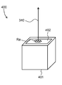
- 4A and 4B are diagrams for explaining the configuration of the light adjustment device 400.
- FIG. FIG. 4A is a perspective view illustrating an appearance of the light adjustment device 400.
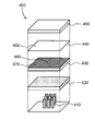
- FIG. FIG. 4B is an exploded perspective view showing the configuration of the light adjustment device 400.
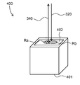
- the displacement adjustment system 500 includes a surgery support system 100 and a light adjustment device (light source device) 400.
- the deviation adjustment system 500 is an example of a projection system.
- positioning state of the optical adjustment apparatus 400 with respect to the surgery assistance system 100 in the deviation adjustment system 500 is shown.
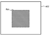
- the light adjustment device 400 includes a projection surface 402 that is a target of imaging and projection operations of the surgery support system 100 on one surface of a box-shaped housing 401 and a light source inside the housing 401. It is a device equipped.
- the projection surface 402 of the light adjustment device 400 is also an emission surface of LED (Light Emitting Diode) light 340 emitted from the inside of the housing 401.
- LED Light Emitting Diode
- the light adjustment device 400 includes a white LED 410, a diffusion plate 420, an opening mask 430, a screen material 440, and a protective glass 450. Inside the housing 401 of the light adjusting device 400, the white LED 410, the diffusion plate 420, the opening mask 430, the screen material 440, and the protective glass 450 are sequentially stacked.
- the white LED 410 is a semiconductor light emitting element that emits white LED light 340.
- the wavelength spectrum of the light emitted by the white LED 410 includes not only the visible light region but also the invisible light region (including the infrared region).
- the white LED 410 is used as the light source of the light adjustment device 400, but the present invention is not limited to this.
- a light source having a spectrum including a visible light component and a non-visible light component including an infrared wavelength component
- a light source may be configured by arranging both a light emitting element that emits only visible light, such as a monochromatic LED, and a light emitting element that emits only infrared light, inside the housing 401.
- a light emitting element that emits only visible light such as a monochromatic LED
- a light emitting element that emits only infrared light inside the housing 401.
- the diffusion plate 420 is formed of a resin plate having a ground glass-like rough surface, for example.
- the diffusion plate 420 is disposed inside the housing 401 so as to face the white LED 410.
- the diffuser plate 420 emits surface light by reducing unevenness in luminance of light emitted from the white LED 410. Note that the light adjustment device 400 may not include the diffusion plate 420.
- the opening mask 430 is a light shielding member in which an opening 460 is provided in the light shielding surface 470.
- the opening mask 430 is disposed inside the housing 401 of the light adjustment device 400 so as to face the white LED 410 via the diffusion plate 420.
- the opening 460 is a hole having a predetermined size facing the white LED 410, and light emitted from the white LED 410 passes through the opening 460.
- the light shielding surface 470 surrounds the opening 460 and shields light incident from the white LED 410.
- the size of the opening 460 and the location on the light shielding surface 470 in the opening mask 430 are determined according to the purpose of measurement. For example, in order to check whether the deviation is 2 mm or less, an opening 460 having a size of 2 mm or less is formed in the opening mask 430.
- the screen material 440 is a light-scattering sheet-like member, and has a projection surface 402 on one main surface.
- the screen material 440 is disposed to face the opening mask 430 with the main surface that is not the projection surface 402 facing the opening mask 430. At least a visible light component of the light emitted from the white LED 410 is scattered by the screen material 440.
- the light emitted from the white LED 410 is irradiated, and the viewing angle of the reference region Ra, which is the exiting region, is widened, making it easy for humans to visually recognize.
- the reference region Ra irradiated from the white LED 410 is formed in a size according to the setting of the opening 460, and serves as a reference for visually recognizing the positional deviation in the deviation adjustment method described later.
- the material of the screen material 440 is, for example, paper.
- the color of the paper is arbitrary, and may be a color (for example, a complementary color) that is easy to visually recognize according to the color of the laser light to be irradiated. Further, the material of the screen material 440 may be cloth instead of paper.
- the material of the screen material 440 may be any material that scatters at least part of the visible light component of the incident light and has a small scattering rate of the infrared wavelength component.
- the protective glass 450 is a glass member that protects the screen material 440 from scratches.
- the light adjusting device 400 may not include the screen material 440 and the protective glass 450.
- FIGS. 3 and 5A to 5E are diagrams for explaining the shift adjustment by the light adjustment device 400.
- FIG. 5A is a perspective view of the light adjustment device 400 during adjustment of misalignment.
- FIG. 5B shows an example of the state of the projection surface 402 when the deviation is not adjusted.
- FIG. 5C shows an image for projection in the example of FIG. 5B.
- FIG. 5D shows an image for projection obtained by adjusting the shift of the image of FIG. 5C.
- FIG. 5E shows an example of the state of the projection plane 402 after the shift adjustment.
- This adjustment method is performed, for example, by an adjustment worker of a manufacturer as an adjustment operation in the manufacturing stage of the imaging irradiation apparatus 200 or the surgery support system 100.
- the shipment product of the imaging irradiation apparatus 200 or the surgery support system 100 is already adjusted.
- this adjustment method can also be performed as a confirmation work just before the actual surgery.
- the adjustment operator sets the light adjustment device 400 directly under the imaging irradiation device 200, and the irradiation of the imaging surface of the infrared camera 210 and the visible laser light 320. Place it at the position facing the mouth.
- the allowable height range that is the allowable range (height) between the imaging irradiation apparatus 200 and the operating table 110 is 1000 mm ⁇ 300 mm
- the distance from the lower surface of the imaging irradiation apparatus 200 is 1000 mm.
- the light adjustment device 400 is disposed at the position of.
- the adjustment operator irradiates the LED light 340 from the white LED 410.
- the LED light 340 enters the screen material 440 through the aperture mask 430 and exits from the reference region Ra on the projection surface 402.
- the visible light component of the LED light 340 generates scattered light.
- the scattered light of the visible light component of the LED light 340 forms an image showing the reference region Ra (hereinafter referred to as “reference region image” Ra) on the projection surface 402 (see FIG. 4A).
- the LED light 340 emitted from the white LED 410 includes a wavelength band component in the infrared region.
- the wavelength band component in the infrared region of the LED light 340 passes through the dichroic mirror 211 of the surgery support system 100.
- the surgery support system 100 performs the above-described projection operation using the projection surface 402 of the light adjustment device 400 as an imaging and projection target.
- the infrared camera 210 receives light transmitted through the dichroic mirror 211 and captures an image of the projection plane 402. Therefore, the infrared camera 210 captures an image of the reference region Ra that emits light including a wavelength band component in the infrared region.
- the infrared camera 210 transmits the captured image to the control device (adjustment unit) 230.
- the control device 230 calculates, for example, XY coordinates from one vertex of the captured image, thereby emitting a reference region image Ra that emits light in the infrared wavelength band. Get information indicating the coordinates of.
- the control device 230 manages the coordinates in the captured image transmitted from the infrared camera 210 and the scanning coordinates that irradiate the visible laser light 320 in a one-to-one correspondence on the image data, for example.
- the control device 230 controls the MEMS mirror 221 so that the visible laser light is irradiated to the scanning coordinates corresponding to the acquired coordinates.
- the projection unit 220 irradiates the light adjustment device 400 with the visible laser light 320 in accordance with the infrared light emission from the light adjustment device 400, whereby a projection image Rb is displayed on the projection surface 402 as shown in FIG. 5A. Project.
- the reference area image Ra to be imaged by the imaging irradiation device 200 and the projection image Rb by the imaging irradiation device 200 are each reflected in visible light, and the adjustment operator , Both can be seen together.
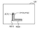
- the reference region image Ra by the LED light 340 and the projection region of the projection image Rb by the visible laser beam 320 should be essentially the same. However, in actuality, there may be a deviation between the positions due to assembly errors or the like. In such a case, according to the light adjustment device 400, as shown in FIG. 5B, the positional deviations ⁇ x and ⁇ y between the position of the reference area image Ra and the position of the projection image Rb can be visually recognized.
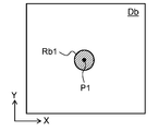
- the control device 230 stores in the memory 240 information indicating the irradiation position of the visible laser beam 320 when the deviation is not adjusted (that is, the scanning position of the MEMS mirror 221). At this time, as shown in FIG. 5C, the control device 230 generates a video signal indicating an image Db on which the projection image Rb1 based on the imaging result of the reference region image Ra is arranged. Based on this video signal, the projected image Rb by the visible laser beam 320 is projected onto the projection surface 402. The projected image Rb is projected at a position shifted from the reference area image Ra as shown in FIG. 5B.
- the control device 230 stores in the memory 240 the unadjusted position P1 of the projection image Rb1 on the image Db when the deviation is not adjusted.
- This position (scanning position) P1 is hereinafter referred to as “unadjusted position”.
- the adjustment operator compares the reference area image Ra projected on the projection surface 402 with the projection image Rb while visually observing them, and uses a control device (not shown) or the like so that the positions of the two match.
- the shift amount is input to 230. Specifically, information related to the movement amount for shifting the projection image on the X axis or the Y axis is input to the control device 230.
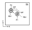
- the control device 230 controls the projection unit 220 so as to change the irradiation position of the visible laser beam 320 (scanning position by the MEMS mirror 221) based on the input information. For example, based on the input information indicating the movement amount, the control device 230 shifts the irradiation position in the image Db by the movement amounts ⁇ xd and ⁇ yd indicated by the input information from the unadjusted position P1, as shown in FIG. 5D.
- the movement amounts ⁇ xd and ⁇ yd on the image are values corresponding to the actual positional deviation amounts ⁇ x and ⁇ y on the projection surface 402.
- the projection image Rb2 is projected at a position on the projection surface 402 corresponding to the adjusted irradiation position P2, and coincides with the reference region image Ra.
- the control device 230 stores the final irradiation position P2 (that is, the scanning position of the MEMS mirror 221) on the image Db in the memory 240.
- This irradiation position (scanning position) P2 is hereinafter referred to as “adjusted position”.
- the control device 230 calculates a deviation correction amount based on the unadjusted position P1 and the adjusted position P2 stored in the memory 240. Specifically, the difference between the unadjusted position P1 and the adjusted position P2 is calculated as a deviation correction amount.
- the movement amounts ⁇ xd and ⁇ yd are stored in the memory 240 as deviation correction amounts.
- the control device 230 After performing the above deviation adjustment, the control device 230 corrects the irradiation position of the visible laser beam 320 based on the deviation correction amount stored in the memory 240 and projects a projection image. As a result, the projection image is accurately projected on the projection target.
- FIG. 6 shows an example of the state of the projection surface 402 when the light adjustment device 400 is used in the arrangement shown in FIG.
- the diameter La of the circular reference region image Ra shown in FIG. 6 is set to coincide with a predetermined allowable error according to the specifications of the surgery support system 100.
- the diameter La is set according to the size of the opening 460 of the opening mask 430 (see FIGS. 4A and 4B).
- the diameter La is set to 2 mm.
- the positional deviation ⁇ L between the reference area image Ra and the projection image Rb is less than the diameter La. Therefore, the projection accuracy of the surgery support system 100 is within the allowable error range.
- the positional deviation ⁇ L is larger than the diameter La, so that it can be determined that the projection accuracy is outside the allowable error range. Therefore, the user of the light adjustment device 400 easily confirms whether the positional deviation is within the allowable error range by visually confirming whether or not at least a part of the reference area image Ra and the projection image Rb overlap. can do.
- the above-described operation of the control device 230 for adjusting the deviation may be omitted.
- the shape of the reference region image Ra is circular.
- the shape of the reference region image Ra is not particularly limited, and may be an ellipse, a polygon such as a triangle or a rectangle, or other shapes. Good.
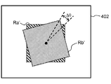
- a plurality of reference areas may be formed on one projection surface 402. As an example, a deviation adjustment method when the reference area image is a square will be described with reference to FIGS. 7A to 7C.
- FIG. 7A is a plan view of the opening mask 430 '.
- FIG. 7B shows a state where a light emission image by the white LED 410 is projected on the projection plane 402 using the opening mask 430 ′.
- FIG. 7C shows a state where the projection operation of the surgery support system 100 is performed on the projection plane 402 shown in FIG. 7B with the arrangement shown in FIG.
- a square reference area image Ra ' is projected on the projection surface 402 as shown in FIG. 7B.
- the angle deviation ⁇ can be visually recognized by comparing one vertex of the reference area image Ra ′ and the projection image Rb ′. Therefore, it is possible to make an adjustment while visually recognizing the angle deviation ⁇ , similarly to the adjustment for the position deviations ⁇ x and ⁇ y.
- the deviation adjustment system 500 includes the light adjustment device 400, the infrared camera 210, and the projection unit 220.
- the light adjusting device 400 has a projection surface 402 including a reference region Ra, and irradiates LED light 340 including invisible light and visible light from the reference region Ra.
- the infrared camera 210 receives invisible light and images the projection surface 402.
- the projection unit 220 projects a projected image Rb of visible light onto the projection surface 402 based on the captured image captured by the infrared camera 210.
- the LED light including the visible light is irradiated from the reference region Ra included in the projection surface 402 of the light adjustment device 400, and the projected image Rb of the visible light based on the captured image of the reference region Ra is applied to the projection surface 402. Projected. Therefore, the deviation between the reference region Ra, which is the subject on the projection surface 402, and the projection image Rb is visualized, and the deviation between the subject and the projection image in the projection system that images the subject and projects the projection image can be easily adjusted. .
- the deviation adjustment method is an adjustment method for adjusting the projection image G320 projected on the affected part 140 in the surgery support system 100.
- the surgery support system 100 receives the infrared fluorescence 310 and images the affected area 140, and generates a visible light projection image G 320 based on the captured image of the affected area 140 and projects the image onto the affected area 140. Part 220.
- the LED light 340 having a spectrum including a visible light component and an infrared wavelength component (including a wavelength of 850 nm) in the reference region Ra on the projection plane 402 that is an object of imaging and projection operations of the surgery support system 100 is used. Irradiating.
- the deviation adjustment method includes a step of imaging the reference region Ra of the projection surface 402 by the infrared camera 210.
- the deviation adjustment method includes a step of projecting onto the projection surface 402 a projection image Rb based on the reference region Ra of the imaged projection plane 402 by the projection unit 220.
- the deviation adjustment method includes a step of comparing the reference region Ra and the projection image Rb on the projection plane 402.
- the deviation adjustment method includes a step of adjusting the position of the projection image Rb based on the comparison result.
- the light adjustment device 400 is an adjustment device for adjusting the projection image G320 projected on the affected part 140 in the surgery support system 100.
- the light adjustment device 400 includes a white LED 410 and a projection surface 402.
- the white LED 410 emits LED light 340 having a spectrum including a visible light component and an infrared wavelength component (including a wavelength of 850 nm).
- the projection surface 402 has a predetermined reference area Ra irradiated with the (white) LED light 340 from the white LED 410, and is a target of the imaging and projection operations of the surgery support system 100.
- the visible laser beam 320 is irradiated to the region where the infrared fluorescence 310 that is the fluorescence of ICG is detected.
- the infrared light included in the white LED 410 of the light adjustment device 400 is irradiated. Is performed in the manner of ICG infrared fluorescence.
- the deviation between the irradiation position of the visible light laser 222 and the imaging position of the infrared camera 210 is visualized on the projection surface 402, and the deviation can be easily adjusted.
- the projection surface 402 is the main surface of the screen material 440.
- the present invention is not limited to this.
- the light shielding surface 470 of the aperture mask 430 is used as the projection surface. It is good. Even in this case, the reference region for emitting the LED light 340 is formed by the opening 460.
- the reference region Ra is formed by the opening 460.
- the reference region Ra is not limited to this, and the LED light 340 is guided by using a reflecting mirror, a lens, and the like, and is incident on the projection surface 402. A region may be formed.
- the projection image is adjusted by signal processing based on the amount of deviation correction.
- the deviation adjustment method according to the present embodiment is not limited to this.
- the physical arrangement of the infrared camera 210 and the visible light laser 222 may be adjusted while viewing the projection surface 402 of the light adjustment device 400. Good.
- the adjustment operator operates the operation unit to align the reference region Ra and the projection image Rb.
- the control device 230 may compare the reference region Ra and the projection image Rb on the projection surface 402 and adjust the position of the projection image based on the comparison result.
- the projection surface 402 may be imaged with a visible light camera, the positions of the reference region Ra and the visible light region Rb may be specified, and the control device 230 may perform alignment. For example, the number of dots on the captured image of the visible light camera may be counted and converted into a correction amount.
- the control device 230 may execute such processing using a predetermined program.
- the present invention is not limited to this.
- the correction amount ⁇ d of the rotation angle ⁇ and the correction amount of the projection magnification Z ⁇ Zd may be stored in the memory 240.
- the projection magnification Z and the correction amount ⁇ Zd may be set as a zoom value by an optical system such as a zoom lens for projecting the projection image, or may be set as a digital value in signal processing of the projection image. .
- the correction amount ⁇ d can be extracted based on the angle deviation ⁇ shown in FIG. 7C.
- the correction amount ⁇ Zd can be extracted by comparing the distance between the two vertices of the reference region Ra ′ and the projection image Rb ′ shown in FIG. 7C.
- the arrangement of the light adjustment device 400 may be changed and captured by a visible light camera, and the distortion of the projection image may be extracted and corrected by comparing the reference region image Ra and the projection image Rb.
- the shift is adjusted by using one light adjusting device 400, but a plurality of light adjusting devices 400 may be used. Accordingly, the arrangement of the light adjustment device 400 can be changed without changing the adjustment time, and the adjustment time can be shortened and the adjustment accuracy can be improved.
- the deviation adjustment method has been described in the case where the projection unit 220 has the visible light laser 222 and scans the laser irradiation, but the projection method of the projection image is not limited to this, and the projection is performed by other methods. Even when an image is projected, a deviation adjustment method using the light adjustment device 400 can be performed.
- the surgery support system 100 employs a laser scanning projection using the projection unit 220 having the visible light laser 222 and the MEMS mirror 221. Specifically, while being able to supply high-intensity light by the visible light laser 222, the MEMS mirror 221 is visible only to the inside or boundary of the region of the affected area 140 detected and identified by the infrared camera 210. The laser beam 320 is scanned. This makes it easy to visually recognize the projected image even in a high illumination environment while considering safety.
- FIG. 8A and 8B are diagrams for explaining the infrared fluorescence 310 and the visible laser beam 320 before and after the shift adjustment.
- FIG. 9 is a diagram for explaining a scanning pattern by the visible light laser 222 and the MEMS mirror 221.
- the operating table 110 on which a patient 130 is placed is located immediately below the imaging irradiation apparatus 200 and at a position facing the imaging surface of the infrared camera 210 and the irradiation port of the visible laser light 320.
- the allowable range based on the focal length of the infrared camera 210 is, for example, 1000 mm ⁇ 300 mm
- the body axis of the patient 130 is positioned at a position where the distance from the lower surface of the imaging irradiation device 200 is 1000 mm.
- the usage height of the imaging irradiation apparatus 200 or the usage height of the operating table 110 is adjusted.
- ICG has already been administered into the blood of the patient 130 and the ICG has accumulated in the affected area 140.
- the patient 130 starts the operation of the surgery support system 100 with the body part into which the scalpel is inserted with respect to the affected part 140 being placed on the operating table 110.
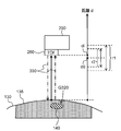
- the control device 230 controls the infrared excitation light source 250 to irradiate the surgical field 135 in the vicinity of the affected area 140 of the patient 130 with the infrared excitation light 300 before and after the excitation wavelength 800 nm of ICG. .
- the ICG accumulated in the affected part 140 causes an excitation reaction by the infrared excitation light 300 and emits infrared fluorescence 310 having a peak wavelength near 850 nm.
- a part of the infrared fluorescence 310 emitted from the ICG accumulated in the affected part 140 passes through the dichroic mirror 211.
- the infrared camera 210 receives the infrared fluorescence 310 transmitted through the dichroic mirror 211 and images the operative field 135. Therefore, an infrared fluorescent region R310 that emits infrared fluorescence 310 appears in the image captured by the infrared camera 210.
- the infrared camera 210 transmits the captured image to the control device 230
- the control device 230 specifies the coordinates of the emission region of the infrared fluorescence 310 (for example, the XY coordinates from one vertex of the captured image) based on the captured image transmitted from the infrared camera 210. At this time, the control device 230 reads ⁇ x and ⁇ y that are deviation correction amounts stored in the memory 240. Further, the control device 230 calculates a corrected coordinate obtained by correcting the deviation correction amount read from the memory 240 with respect to the coordinate specified based on the captured image transmitted from the infrared camera 210.
- the control device 230 controls the MEMS mirror 221 so as to irradiate the visible laser beam 320 with a laser scanning pattern set in advance at a scanning coordinate corresponding to the coordinate correction coordinate in the captured image transmitted from the infrared camera 210. . Details of the laser scanning pattern will be described later.
- FIG. 8A shows the infrared fluorescent region R310 of the infrared fluorescence 310 of ICG and the projection region R320 'by the visible laser beam 320 when correction based on the shift correction amount is not performed.
- the visible laser beam 320 is irradiated to a position shifted by ⁇ x and ⁇ y from the infrared fluorescent region R310 of ICG.
- FIG. 8B shows the infrared fluorescence region R310 of the infrared fluorescence 310 of ICG and the projection region R320 by the visible laser beam 320 when correction based on the shift correction amount is performed.
- the visible laser beam 320 is accurately irradiated to the infrared fluorescent region R310 of the ICG.
- FIG. 9 shows raster scanning and vector scanning that can be selected as a laser scanning pattern by the surgical operation support system 100.
- the raster scanning is a scanning pattern in which the reciprocating irradiation operation of the visible laser beam 320 is performed so that only the inside of the affected area 140 that emits the infrared fluorescence 310 is coated with a surface.
- the illuminance magnification is set to 1.
- the illumination intensity on the irradiated surface is about 250000 lux when the irradiation area takes the maximum value (when 100 mm square) and about 25 when the irradiation area takes the minimum value (when 10 mm square). 10,000 lux.
- the vector scanning is a scanning pattern in which the irradiation operation of the visible laser beam 320 is performed so as to draw a line only on the boundary of the region of the affected part 140 that emits the infrared fluorescence 310.
- the illuminance magnification is set to 20 times.
- the illumination intensity on the irradiated surface is about 50,000 lux when the irradiation area takes the maximum value (when 100 mm square) and about 5 million lux when the irradiation area takes the minimum value (when 10 mm square). It becomes.
- the doctor can switch and set whether to perform visible light laser irradiation by raster scanning or visible light laser irradiation by vector scanning by operating an operation unit (not shown) according to the operation contents and the like. .
- raster scanning and vector scanning are illustrated as scanning patterns, but the scanning pattern is not limited to this.
- a derived pattern of raster scanning only the inside of the affected area 140 that emits the infrared fluorescence 310 is scanned, but a pattern in which thinning of scanning is appropriately performed may be employed.
- a derived pattern of raster scanning or vector scanning a pattern in which the same position is scanned a plurality of times and then the irradiation position is shifted to another position may be adopted.
- the control device 230 causes the projection unit 220 to project the projected image by irradiating the region of the affected part 140 that emits the infrared fluorescence 310 with the visible laser light 320 based on the set scanning pattern. At this time, the control device 230 controls the MEMS mirror 221 to perform visible light laser irradiation based on the set scanning pattern. The control device 230 continues the scanning operation continuously even after the scanning of the region of the affected part 140 that emits the infrared fluorescent light 310 or the boundary is completed.
- the surgery support system 100 includes the infrared camera 210, the projection unit 220, and the control device 230.
- the infrared camera 210 images the affected part 140.
- the projection unit 220 generates a projected image G320 of visible light based on the captured image captured by the infrared camera 210 and projects it onto the affected part 140.
- the control device 230 controls the operations of the infrared camera 210 and the projection unit 220.
- the projection unit 220 includes a visible light laser 222 that irradiates the visible laser light 320.
- the control device 230 controls the projection unit 220 so as to scan the visible laser light 320 with a predetermined scanning pattern in the projection region R320 where the projection image G320 is projected.
- the surgery support system 100 since a high-illuminance laser light source is used as an irradiation light source, visibility can be improved even in a high-illuminance environment with other illumination devices such as a surgical light 120. Furthermore, since scanning is performed only on the inside or boundary of a specific area with a predetermined scanning pattern, it is possible to obtain illuminance compared to irradiating a wide area and to improve visibility. Moreover, the irradiation position is scanned instead of continuing to irradiate the high-illuminance visible laser beam 320 to the same location. Accordingly, it is possible to provide the surgical operation support system 100 that facilitates visual recognition even in a high illumination environment while considering safety.
- the scan pattern may be a raster scan that scans the visible laser beam 320 within the projection region R320.
- the scan pattern may be a vector scan that scans the visible laser beam 320 along the boundary of the projection region R320.
- the projection unit 220 may further include a MEMS mirror 221 having a plurality of micromirror surfaces that reflect the visible laser beam 320.
- the control device 230 may control the projection unit 220 so as to scan the visible laser light 320 while changing the inclination angle of each micromirror surface of the MEMS mirror 221. Thereby, the processing amount in the scanning of the visible laser beam 320 can be reduced.
- the inventor projects a cutting auxiliary line 321 that supports the determination of the cutting position where the scalpel is inserted as accompanying information, in addition to the projection of the visible light projection image G320 that displays the region of the affected part 140 in which ICG is accumulated. Came up with the idea. Thereby, it is possible to support the reproduction of the cutting position planned before the start of the operation, and it is possible to reduce the burden on the doctor. Moreover, the time spent at the start of surgery can be shortened.
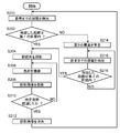
- FIG. 10 is a flowchart showing the projection operation of the auxiliary cutting line 321 according to the detection of the affected part 140.
- 11A and 11B are diagrams for explaining the projection operation of the cutting auxiliary line 321 according to the detection of the affected part 140.
- FIG. 10 is a flowchart showing the projection operation of the auxiliary cutting line 321 according to the detection of the affected part 140.
- 11A and 11B are diagrams for explaining the projection operation of the cutting auxiliary line 321 according to the detection of the affected part 140.
- FIG. 10 is a flowchart showing the projection operation of the auxiliary cutting line 321 according to the detection of the affected part 140.
- 11A and 11B are diagrams for explaining the projection operation of the cutting auxiliary line 321 according to the detection of the affected part 140.
- the doctor cuts so as to insert a scalpel with a certain distance (hereinafter referred to as “cutting margin width”) with respect to the affected part 140.
- cutting margin width a scalpel with a certain distance
- you have planned a location.
- the doctor has input the planned cutting margin into the surgery support system 100 using an operation unit (not shown).
- the doctor inputs information indicating the cutting auxiliary line condition that the cutting margin width is 2 centimeters to the surgery support system 100.
- the control device 230 of the surgery support system 100 stores the cutting margin width in the memory 240 based on the input information.
- the flow shown in FIG. 10 is started when an operation supported by the operation support system 100 is started in a state where information indicating the condition of the auxiliary cutting line is stored in the memory 240.
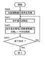
- control device 230 reads the cutting margin width and the like stored in the memory 240 and acquires the cutting auxiliary line condition (S400).
- the control device 230 causes the infrared camera 210 to capture a fluorescence image of the infrared fluorescence 310 emitted from the ICG in response to the infrared excitation light 300 (S401). At this time, the control device 230 specifies the coordinates of the region emitting infrared fluorescence from the captured image transmitted from the infrared camera 210. Further, the control device 230 reads out the deviation correction amount from the memory 240 and calculates a corrected coordinate obtained by correcting the deviation correction amount with respect to the coordinate specified based on the captured image transmitted from the infrared camera 210. In this way, the control device 230 detects the infrared fluorescent region R310 of the affected part 140.
- control device 230 starts irradiation with the visible laser beam 320 based on the calculated correction coordinates (S402). At this time, the control device 230 calculates the position at which the auxiliary cutting line 321 is projected based on the detected infrared fluorescent region R310 and the cutting margin width acquired in step S400. Then, the control device 230 performs laser scanning on the area specified as the affected area 140 and irradiates the cutting auxiliary line 321 at a position separated from the area specified as the affected area 140 by a cutting margin width. To control.
- the control device 230 adjusts the projection magnification based on the distance information detected by the TOF sensor 260.
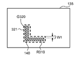
- the control device 230 causes the MEMS mirror 221 to irradiate the cutting auxiliary line 321 at a position separated by 2 centimeters from the region identified as the affected part 140. Control.
- the cutting auxiliary line 321 is projected around the area identified as the affected area 140 at a position separated by 2 centimeters to resemble the area identified as the affected area 140.
- the projection of the cutting auxiliary line 321 will be described in more detail with reference to FIGS. 11A and 11B.
- FIG. 11A shows the operative field 135 in a state where the projection operation of the cutting auxiliary line 321 corresponding to the detection of the affected part 140 is performed when the first cutting margin width W1 is set.
- FIG. 11B shows the operative field 135 in a state where the projection operation of the cutting auxiliary line 321 corresponding to the detection of the affected part 140 is performed when the second cutting margin width W2 is set.
- the second cutting margin width W2 is set to a value larger than the first cutting margin width W1.
- the visible light projection image G320 is projected on the infrared fluorescent region R310 of the affected area 140 that emits the infrared fluorescent light 310 in the operative field 135 by detecting the infrared fluorescent light 310 in the captured image.
- the control device 230 Based on the distance information detected by the TOF sensor 260 in addition to the irradiation position of the projection image G320, the control device 230 surrounds the infrared fluorescent region R310 with an interval of the cutting margin widths W1 and W2 in the operative field 135. In this way, the irradiation position of the visible laser beam 320 for projecting the auxiliary cutting line 321 is set. Therefore, as illustrated in FIGS. 11A and 11B, the surgery support system 100 can change the position at which the auxiliary cutting line 321 is irradiated according to the cutting position plan (cutting margin width) by the doctor.
- the margin for cutting may be set in advance by the surgery support system 100 such that the separation size is small (for example, 2 mm) or the separation size is large (for example, 10 mm). It is also possible to set an arbitrary cutting margin.
- the shape of the auxiliary cutting line 321 may be a solid line, a dotted line, a line that is a combination of points and lines such as a one-dot chain line, a two-dot chain line, etc., in addition to the broken line as shown in FIGS.
- a line other than the solid line is preferable so that it can be easily distinguished from the projection image G320.
- the line width of the auxiliary cutting line 321 is good enough for the doctor to visually recognize and understand the cutting site.
- the line width is preferably about 2 mm to 5 mm. May be.
- the control device 230 repeats the processing of S401 and S402 until an end instruction is given from the operation unit by a doctor or the like (No in S403).
- the control device 230 ends the irradiation operation of the visible laser beam 320.
- the conditions for the cutting auxiliary line 321 are the cutting margin widths W1 and W2.
- the condition of the cutting auxiliary line 321 is not limited to this, and may be a threshold value in the intensity distribution of the infrared fluorescence 310, for example.
- the control device 230 determines the boundary of the intensity distribution in the captured image based on the captured image captured by the infrared camera 210 and the threshold set as the condition of the cutting auxiliary line 321 in the process of step S402. And the projection unit 220 is controlled to project the auxiliary cutting line 321 onto the extracted boundary.
- both the threshold value in the intensity distribution of the infrared fluorescence and the cutting margin widths W 1 and W 2 are used, and the cutting margin widths W 1 and W 2 from the boundary of the intensity distribution in the captured image.
- the auxiliary cutting line 321 may be projected at positions that are spaced apart from each other.
- the control device 230 does not use the distance information of the TOF sensor 260 in particular, and the irradiation position by image analysis of the captured image of the infrared camera 210. May be determined.
- the surgery support system 100 includes the infrared camera 210, the projection unit 220, and the control device 230.
- the infrared camera 210 images the affected part 140.
- the projection unit 220 generates a projection image G320 of visible light and projects it onto the affected part 140.
- the control device 230 detects the infrared fluorescent region R310 of the affected part 140 that emits the infrared fluorescence 310 based on the captured image captured by the infrared camera 210.
- the control device 230 projects a projection image G320 indicating the detected infrared fluorescent region R310, and also assists in cutting, which is a projection image indicating an auxiliary line at a position corresponding to a predetermined condition with respect to the detected infrared fluorescent region R310.
- the projection unit 220 is controlled to project the line 321.
- the cutting auxiliary line 321 can be irradiated in addition to the irradiation to the region identified as the affected part 140 based on the cutting margin width input by the doctor prior to the start of the operation. Thereby, it is possible to support the reproduction of the cutting position planned before the start of the operation, and it is possible to reduce the burden on the doctor. Moreover, the time spent at the start of surgery can be shortened.
- the cutting auxiliary line 321 is projected according to the infrared fluorescent region R310 of the affected part 140 detected based on the emission of the infrared fluorescent 310. Therefore, a doctor or the like can visually recognize an auxiliary line that matches the position of the affected part 140 in real time in the operative field 135.
- the position where the auxiliary cutting line 321 is projected may be set at the boundary of the intensity distribution based on the intensity distribution of infrared fluorescence in the captured image.
- the predetermined condition may be cutting margin widths W1 and W2 indicating the distance from the detected infrared fluorescent region R310.
- the surgery support system 100 may further include a TOF sensor 260 that detects distance information indicating the distance to the affected area 140. Based on the distance information detected by the TOF sensor 260, the control device 230 may project the cutting auxiliary line 321 at a position spaced from the detected infrared fluorescent region R310 by the spacing of the cutting margin widths W1, W2.
- the cutting margin width which is a predetermined condition
- cutting assistance is uniformly placed at a position 2 centimeters away from the region identified as the affected part 140.
- the line 321 is irradiated, the present invention is not limited to this.
- the position where the auxiliary cutting line 321 should be irradiated on the region identified as the affected part 140 may be changed according to the cutting margin width.
- the irradiation of the cutting auxiliary line 321 can be appropriately turned ON / OFF according to the operation of a doctor or the like while the visible laser beam 320 is irradiated to the region identified as the affected part 140. It may be. When turned off, the cutting auxiliary line 321 is not irradiated, and only the visible laser beam 320 is irradiated to the region identified as the affected part 140.
- condition (cutting margin width) of the auxiliary cutting line 321 is input prior to the start of the operation.
- the present invention is not limited to this. That is, during the operation, the condition of the auxiliary cutting line 321 may be changed according to the operation of a doctor or the like.
- the color, brightness, etc. of the projection image G320 and the cutting auxiliary line 321 may be changed.
- the affected part 140 and the cutting position can be easily distinguished by setting the cutting auxiliary line 321 to green or red.
- a doctor performs an operation while checking vital data of the patient 130 as appropriate.
- the vital data includes blood pressure, heart rate (pulse rate), oxygen concentration, electrocardiogram and the like.
- the doctor can perform an operation according to a change in the condition of the patient 130 by checking the vital data.
- the doctor performs an operation while checking the examination image of the patient 130 as appropriate.
- the inspection image includes an image obtained by MRI (Magnetic Resonance Imaging), CT (Computed Tomography), X-ray and the like.
- the doctor can perform an operation according to the test result of the patient 130 by checking the test image.
- the doctor performs an operation while confirming a memo that describes an operation procedure and precautions for the operation, if necessary.
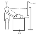
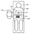
- FIG. 12A is a diagram showing a state of conventional surgery.
- the surgical assistance information is displayed on the monitor 142.
- the doctor 141 performs an operation on the patient 130 while confirming the operation assistance information displayed on the monitor 142.
- the doctor 141 is burdened and spends confirmation time.
- the inventor came up with the idea of projecting the auxiliary surgery information 151 around the affected area 140 as accompanying information in addition to the projection of the visible light image on the area identified as the affected area 140.
- doctors or the like can reduce line-of-sight movement during surgery.
- the burden on the doctor or the like can be reduced and the confirmation time can be shortened.
- FIG. 12B is a diagram for explaining the projection of the surgical assistance information 151 around the affected area 140.
- 13A and 13B are diagrams for explaining the projection of the surgical auxiliary information 151 onto the auxiliary screen material 150.
- the control device 230 of the surgery support system 100 is communicably connected to a medical device (not shown) that acquires various vital data. As a result, the control device 230 acquires vital data necessary for the surgery in real time from the medical devices that are communicably connected.
- the examination image data of the patient 130 and the memo such as the operation procedure are stored in the memory 240 in advance before the operation is started by the operation of the operation unit by the doctor 141 or the like.
- the control device 230 reads out and acquires examination image data necessary for the operation and a memo such as an operation procedure from the memory 240.
- FIG. 12B is a diagram showing a state of projection of the surgical auxiliary information 151 according to the present embodiment.
- the doctor 141 or the like arranges the auxiliary screen material 150 that projects the operation auxiliary information 151 in the vicinity of the affected part 140 of the patient 130 as shown in FIG. 12B.
- the auxiliary screen material 150 may be made of any material as long as it can display a projected image. Further, the auxiliary screen material 150 may be of any shape and size as long as it can be placed in the vicinity of the affected area 140.
- the auxiliary screen material 150 is arranged on the right side of the affected part 140 when viewed from the doctor 141, but the arrangement position is not limited to this. You may arrange
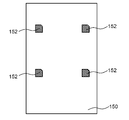
- FIG. 13A is a top view of the auxiliary screen material 150 in a state where the surgical auxiliary information is not projected.
- a marker 152 is attached to the upper surface of the auxiliary screen material 150.
- the marker 152 is positioned on the auxiliary screen material 150 as a reference indicating a region for displaying the surgical auxiliary information 151 on the auxiliary screen material 150.
- a camera (not shown) is connected to the control device 230 of the surgery support system 100, and the camera images the marker 152 attached on the auxiliary screen material 150.
- the camera transmits the captured image of the marker 152 to the control device 230.
- the memory 240 stores in advance a correspondence relationship between the imaging region in the captured image of the camera and the projection region of the surgical assistance information by the visible light laser 222 in advance.
- the control device 230 specifies a region on which the surgical auxiliary information 151 is projected from the correspondence relationship stored in the memory 240 and the detection result of the position of the marker 152 from the transmitted captured image.
- the control apparatus 230 controls the MEMS mirror 221 so that the surgery assistance information 151 is projected with respect to the specified area
- a projection image G ⁇ b> 151 indicating the surgical auxiliary information 151 is projected on the upper surface of the auxiliary screen material 150.
- the surgery support system 100 projects the projection image G151 of the surgery assistance information 151 onto the auxiliary screen material 150 together with the projection image G320 (see FIG. 2B) for the infrared fluorescent region R310 identified as the affected part 140.
- the doctor can reduce the movement of the line of sight during the operation.
- the burden on the doctor 141 can be reduced, the confirmation time can be shortened, and surgery can be supported.
- the surgical assistance information 151 is projected onto the auxiliary screen material 150, but is not limited thereto.
- the auxiliary surgery information 151 may be projected directly onto the body surface of the patient 130 instead of on the auxiliary screen material 150.
- the marker 152 may be added to the body surface of the patient 130.
- the camera for imaging the marker 152 is used.
- the present invention is not limited to this.
- the infrared camera 210 may image the marker 152.
- the marker 152 is made of a material coated with ICG, kneaded, or poured. Thereby, the affected part 140 and the marker 152 can be imaged only by the infrared camera 210.
- the region on which the surgical auxiliary information 151 is projected by the marker 152 is specified, but the present invention is not limited to this. That is, you may specify the area
- the operation assistance information 151 may be projected at a position away from a position where the affected part 140 is irradiated with the visible laser light 320 in a distance and direction set in advance by a doctor.
- the setting is made in advance so as to project to the position of 20 centimeters to the right from the rightmost end of the region identified as the affected part 140 as seen from the doctor 141.
- the control device 230 controls the MEMS mirror 221 so as to project the surgical auxiliary information 151 to a preset position with respect to the region identified as the affected part 140.
- the operation assistance information 151 can be projected to an arbitrary place that can be easily confirmed by the doctor 141.
- the control device 230 may calculate the position at which the surgical auxiliary information 151 is projected in the surgical field 135 based on the distance information detected by the TOF sensor 260.
- the surgery support system 100 includes the infrared camera 210, the projection unit 220, and the control device 230.
- the infrared camera 210 images the affected part 140.
- the projection unit 220 generates a projection image G320 of visible light and projects it onto the affected part 140.
- the control device 230 controls the projection operation of the projection unit 220 based on the captured image captured by the infrared camera 210.
- the control device 230 projects a projection image G320 showing the imaged affected part 140, and projects a projection image G151 showing operation assistance information 151, which is information related to the operation on the affected part 140, in the vicinity of the affected part 140. 220 is controlled.
- the projection image G151 is projected in the vicinity of the affected part 140, and the movement of the line of sight from the affected part 140 when the doctor or the like confirms the operation assistance information 151 can be reduced, and the burden on the doctor or the like during the operation can be reduced.
- the surgery support system 100 may further include an auxiliary screen material 150 that is disposed in the vicinity of the affected part 140 and has the marker 152.
- the control device 230 projects the projection image G151 on the auxiliary screen material 150 with the position of the marker 152 as a reference.
- the surgery support system 100 may further include a camera that images the marker 152, or the infrared camera 210 may image the marker 152.
- the surgery support system 100 may further include a memory 240 that stores the surgery assistance information 151.
- the control apparatus 230 may acquire the surgery assistance information 151 by communication with an external device.
- the surgery support system 100 may further include a distance detection unit such as a TOF sensor 260 that detects distance information indicating a distance to the affected part 140. Based on the detected distance information, the control device 230 may cause the projection unit 220 to project the surgical assistance information 151 at a position away from the affected part 140 by a predetermined distance. In addition, the control device 230 may project the surgical assistance information 151 on a substantially flat region in the vicinity of the affected part 140 based on the detected distance information. For example, the distance detection unit may output a distance image as distance information.
- a distance detection unit such as a TOF sensor 260 that detects distance information indicating a distance to the affected part 140. Based on the detected distance information, the control device 230 may cause the projection unit 220 to project the surgical assistance information 151 at a position away from the affected part 140 by a predetermined distance. In addition, the control device 230 may project the surgical assistance information 151 on a substantially flat region in the vicinity of the affected part 140 based on the detected distance information. For example,
- Imaging irradiation device 8-1 Monitoring height of imaging irradiation device 8-1. Overview of Usage Height Monitoring Operation
- the imaging irradiation apparatus 200 is adjusted to a height allowable range of 1000 mm ⁇ 300 mm according to the focal length of the infrared camera 210.
- the usage heights of the imaging irradiation device 200 and the operating table 110 are adjusted so that the body axis of the patient 130 is located at a distance of 1000 mm from the lower surface of the patient.
- the imaging irradiation device 200 and the operation are performed.
- the usage height of the table 110 is changed.
- a distance detection unit is provided in the imaging irradiation apparatus 200 and the usage height of the imaging irradiation apparatus 200 is monitored during the operation.
- the direction of 130 can be changed, and the height of the operating table can be adjusted.
- a warning is notified so that misidentification of a user such as a doctor can be avoided.
- safety during surgery can be ensured by controlling the projection image not to be projected when the usage height is outside the allowable range.
- a TOF sensor 260 that emits infrared detection light 330 having a wavelength of 850 nm to 950 nm is used as the distance detection unit.
- the infrared detection light 330 radiated from the TOF sensor 260 is reflected by the body surface of the patient 130 and then returned to the TOF sensor 260 and received. At this time, the infrared detection light 330 reflected by the body surface of the patient 130 reaches not only the TOF sensor 260 but also the infrared camera 210.
- the invention is configured to reciprocally control the TOF sensor 260, the infrared excitation light source 250, and the visible light laser 222 in order to monitor the safe usage height while realizing surgical support by detecting the infrared fluorescence 310. Is provided.
- FIG. 14 is a flowchart showing the flow of processing in the usage height monitoring operation.
- 15A and 15B are diagrams for explaining the usage height monitoring operation. This flow is executed by the control device 230 of the surgery support system 100 (see FIG. 1).
- the TOF sensor 260 emits the infrared detection light 330 and receives the reflected wave as shown in FIG. Is detected (S200). In step S200, the TOF sensor 260 emits the infrared detection light 330 for a predetermined period T1 (see FIG. 16). The TOF sensor 260 outputs the detected distance information to the control device 230.
- the control device 230 determines whether or not the detected distance di is within the predetermined first section r1 (S202).
- the first section r1 is a section showing an allowable range in which the surgery support system 100 at a distance between the imaging irradiation apparatus 200 and the affected part 140 can operate normally.
- step S214 the control height is abnormal.
- the warning in step S214 is performed by, for example, generating a message or warning sound indicating that the usage height is “abnormal state” from a speaker (not shown).
- the projection image is not projected onto the affected area 140 as shown in FIG. 15B.
- control device 230 controls the TOF sensor 260 after the elapse of the period T1, and detects the distance di to the patient 130 as in the process of step S200 (S216).
- the control device 230 determines whether or not the detected distance di is within a predetermined second section r2 (S218).
- the second section r2 is a section indicating that the surgery support system 100 is in a position where it can return from an abnormal state.
- control device 230 determines that the detected distance di is not within the second section r2 (NO in S218), the control device 230 repeatedly performs the process of step S216 at a predetermined cycle. On the other hand, when it is determined that the detected distance di is within the second section r2 (YES in S218), the control device 230 sequentially performs the processing from step S204.
- the control device 230 controls the infrared excitation light source 250 (see FIG. 1) when determining that the detected distance di is within the first section r1 (YES in S202).
- the infrared excitation light 300 is irradiated to the surgical field 135 (S204).
- the control device 230 controls the infrared camera 210 to image the affected area 140 of the operative field 135 (S206).
- the control device 230 causes the projection unit 220 to project a projection image G320 of visible light based on the captured image captured in the process of step S206 (S208).
- the processes in steps S202, 204, and 206 are performed in the same manner as the basic projection operation in the above-described surgery support system 100 (see FIG. 2).
- control device 230 determines whether or not a predetermined period T2 has elapsed since the start of irradiation with the infrared excitation light 300 in step S204 (S210).
- the control device 230 repeatedly executes the processes of steps S206 and S208 at a predetermined cycle (for example, 1/60 seconds) until the period T2 elapses (NO in S210).
- control device 230 After the period T2 has elapsed (YES in S210), the control device 230 causes the infrared excitation light source 250 to stop irradiating the infrared excitation light 300 and causes the projection unit 220 to delete the projection image G320 (S212). Following the process of step S212, the control device 230 returns to the process of step S200.
- step S212 the infrared excitation light source 250 stops the irradiation of the infrared excitation light 300. It is good only as well.
- step S200 is performed after the process of step S212, and distance detection can be performed without causing malfunction of the surgery support system 100 by reciprocally controlling the TOF sensor 260 and the projection unit 220 and the like.
- FIG. 16 is a timing chart for explaining operations of the infrared excitation light source 250, the TOF sensor 260, and the visible light laser 222 according to the height determination result.
- the horizontal axis in FIG. 16 represents the time axis.
- a low level in each chart indicates a light-off state, and a high level indicates a light-on state.
- the “lighting state” indicates the ON state of each of the infrared excitation light source 250, the TOF sensor 260, and the visible light laser 222.
- the “light-off state” indicates a power-off state of each of the infrared excitation light source 250, the TOF sensor 260, and the visible light laser 222.
- the control device 230 periodically performs height (distance) determination by the TOF sensor 260. Specifically, as shown in FIG. 16, a period T1 from time t1 to t2, a period T1 from time t3 to t4, a period T1 from time t5 to t6, a period T1 from time t7 to t8, and a period from time t9 to t10.
- T1 a period from time t1 to t2
- a period T1 from time t3 to t4 a period T1 from time t5 to t6
- a period T1 from time t7 to t8 a period from time t9 to t10.
- the TOF sensor 260 is in a lighting state that emits infrared detection light 330.
- the control device 230 controls the infrared excitation light source 250 and the visible light laser 222 to be turned off. That is, the reciprocal control is performed so that the infrared excitation light source 250 and the visible light laser 222 are turned off when the TOF sensor 260 is turned on.
- the period T1 from time t1 to t2, the period T1 from time t3 to t4, the period T1 from time t5 to t6, the period T1 from time t7 to t8, and the period T1 from time t9 to t10 are all as short as 10 msec to 100 msec, for example. Because it is time, it is difficult for humans to perceive it. Therefore, even if reciprocal control is performed in the height determination period, it is possible to perceive that the projected image by the visible laser beam 320 is continuously displayed.
- the control device 230 determines “normal state” as the height determination result in step S202 of FIG. Then, the control device 230 turns on both the infrared excitation light source 250 and the visible light laser 222 during the subsequent period T2 of time t2 to t3.
- the projection image G320 can be projected onto the affected area 140 as usual, and surgical support can be performed normally.
- the control device 230 determines “abnormal state” as the height determination result in step S202.
- the control device 230 maintains both the infrared excitation light source 250 and the visible light laser 222 in the extinguished state even during the period T2 of the subsequent time t4 to t5.
- the distance di indicated by the detection result of the TOF sensor 260 is between the distance d1 at one end of the first section r1 and the distance d2 at one end of the second section r2 (for example, 1250 mm).
- the imaging irradiation apparatus 200 is within the allowable height range, but may be immediately outside the allowable height range because it is close to the limit of the allowable height range. Therefore, a hysteresis width is provided in the second interval r2 shorter than the first interval r1, and the determination process in step S218 in FIG. 14 is performed, whereby the distance di is between the first distance d1 and the distance d2.
- it is determined as an “abnormal state” and in the period T2 from time t6 to t7, the same operation as in the period T2 from time t4 to t5 can be performed to ensure safety.
- the control device 230 determines “normal state” as the height determination result in step S218. Then, the control device 230 turns on both the infrared excitation light source 250 and the visible light laser 222 during the subsequent period T2 of time t8 to t9. As a result, during the period T2 from time t8 to t9, the projection image G320 can be projected onto the affected area 140 as usual, and surgical support can be performed again.
- the surgery support system 100 includes the infrared camera 210, the projection unit 220, the TOF sensor 260, and the control device 230.
- the infrared camera 210 images the affected part 140.
- the projection unit 220 generates a projection image G320 based on the captured image of the diseased part 140 and projects it onto the diseased part 140.
- the TOF sensor 260 detects the distance to the affected part 140.
- the control device 230 controls the operations of the infrared camera 210 and the projection unit 220.
- the control device 230 determines whether or not the distance detected by the TOF sensor 260 is within the first section r1. When the distance detected by the TOF sensor 260 is within the first section r1, the control device 230 generates a projection image G320 and projects it onto the affected area 140.
- the projection image G320 is generated and projected onto the affected part 140 when the distance detected by the TOF sensor 260 is within the first section r1. Therefore, safety when projecting the projection image G320 can be ensured.
- control device 230 issues a predetermined warning when the distance detected by the TOF sensor 260 is not within the first section r1.
- the surgery support system 100 can make a doctor or the like aware that the distance to the affected area 140 exceeds the first section r1, and can ensure safety during use of the surgery support system 100. Therefore, the surgery support system 100 can be made easier to use for a user such as a doctor.
- the projection image G320 may not be projected on the affected part 140 instead of or in addition to the predetermined warning. Thereby, in the surgery support system 100, the projection of the projection image G320 that may be inaccurate because the first section r1 has been exceeded is stopped, and safety during surgery can be improved.
- the infrared camera 210 may receive the infrared fluorescence 310 having the first spectrum and image the affected part 140.
- the TOF sensor 260 may detect the distance to the affected area 140 by emitting infrared detection light 330 having the second spectrum. In this case, the TOF sensor 260 emits the infrared detection light 330 during the first period T1, and does not emit the infrared detection light 330 during the second period T2 different from the first period T1.
- the control device 230 does not project the projection image G320 during the first period T1, and projects the projection image G320 during the second period T2. Thereby, the distance to the affected part 140 can be detected without causing a malfunction in the surgery support system 100.
- the infrared excitation light source 250 and the visible light laser 222 are both turned off when it is determined as “abnormal state”, but the present invention is not limited to this. Either the infrared excitation light source 250 or the visible light laser 222 may be turned off. When the infrared excitation light source 250 is turned off, the ICG infrared fluorescence 310 is not emitted. Therefore, the control device 230 cannot identify the region of the affected part 140, and even if the visible light laser 222 is in a lighting state, the visible laser beam 320 is not irradiated. When the visible light laser 222 is turned off, the visible laser light 320 is not irradiated in the first place.
- the control device 230 may prevent the infrared camera 210 from capturing an image in place of or in addition to the control of the infrared excitation light source 250 and the visible light laser 222. You may control. Further, the MEMS mirror 221 may be controlled not to generate the projection image G320. That is, the control device 230 may control any of the components of the surgery support system 100 so that the projection image G320 based on the imaging result of the infrared camera 210 is not projected.
- the warning may be an operation that outputs information indicating that the distance to the subject such as the affected part 140 is not within the range of the predetermined section.
- a user such as a doctor may be notified of the “abnormal state”.
- the visible light laser 222 may be switched to another wavelength and the color of the visible laser light 320 may be changed for irradiation.
- a warning may be given by projecting a projection image including a text message indicating an “abnormal state”.
- the projection image G320 based on the imaging result of the infrared camera 210 is deleted.
- the present invention is not limited to this.
- a projection image based on the imaging result of the infrared camera 210 may be used as a warning.
- the color of the projected image based on the imaging result of the infrared camera 210 may be changed for projection, or may be projected after flushing.
- the TOF sensor 260 uses the infrared detection light 330 having a spectrum that overlaps the spectrum of the infrared fluorescence 310, but is not limited thereto.
- the TOF sensor 260 may perform distance detection by emitting detection light that does not overlap the spectrum of the infrared fluorescence 310.
- a wavelength filter that blocks the spectrum of the infrared fluorescence 310 may be provided in the light emitting portion of the TOF sensor 260.
- the wavelength band of 850 nm to 950 nm has high atmospheric transmittance, and distance detection is easy. Therefore, the distance detection efficiency can be improved by performing the above-described reciprocal control without using the wavelength filter.
- the use height is monitored by detecting the distance of the TOF sensor 260, but the present invention is not limited to this.
- the distance between the imaging irradiation apparatus 200 and the subject such as the affected part 140 is monitored by detecting the distance of the TOF sensor 260 so that the surgery support system 100 can operate properly even when the direction of the imaging irradiation apparatus 200 changes. May be.
- the state transitions “lighting state” and “light-off state” of the infrared excitation light source 250 and the visible light laser 222 have been described as switching the power source ON / OFF state. It is not limited.
- the “lighting state” and “light-off state” may be realized by switching the light blocking means between the ON state and the OFF state even if the power source of the light source is maintained in the ON state.
- the first embodiment has been described as an example of the technique disclosed in the present application.
- the technology in the present disclosure is not limited to this, and can also be applied to an embodiment in which changes, replacements, additions, omissions, and the like are appropriately performed.
- the medical application such as surgery has been described as an example, but the present invention is not limited to this.
- the present invention can be applied when it is necessary to work on an object whose state change cannot be visually confirmed, such as a construction site, a mining site, a construction site, or a factory that processes materials.
- a fluorescent material is applied to an object that cannot be visually confirmed in a construction site, a mining site, a construction site, or a factory that processes the material.
- the object to be imaged may be an object to be imaged by the infrared camera 210 by being kneaded or poured.
- a heat generation location may be detected by a thermal sensor, and only that portion or only the boundary may be scanned.
- the projection of a cutting auxiliary line and the projection of surgical auxiliary information are not limited to this. That is, the projection of the cutting auxiliary line and the surgical auxiliary information may be performed by a light source other than the laser light source.
- the projection of the cutting auxiliary line and the projection of the surgical auxiliary information have been described in the case where the same visible light laser 222 as the light source of the projection for the region identified as the affected part is used, but is not limited thereto.
- the projection of the cutting auxiliary line and the projection of the surgical auxiliary information may be performed by a light source different from the projection for the region identified as the affected part.
- control is performed so as to perform projection corresponding to the projection for the region identified as the affected area.
- the TOF sensor 260 is used as the distance detection unit, but the present invention is not limited to this.
- it may be a sensor that radiates infrared detection light having a known pattern, such as a random dot pattern, and measures the distance based on the deviation of the reflected wave pattern.
- the distance detection unit can detect the distance information as a distance image representing the distance at each dot in the two-dimensional region.
- the projection image G320 of a single color uniform image by the visible light laser 222 is exemplified.
- the projection image projected by the projection unit is not limited to this, and a projected image with a light and shade or a full-color projected image may be projected, or an arbitrary image may be projected.
- the usable range of the surgery support system 100 of the present embodiment is a range that can be imaged by the infrared camera 210 and a range that can be projected by the projection unit 220.
- the range that can be projected by the projection unit 220 includes a range in which the accompanying information (cutting auxiliary line 321, surgical auxiliary information 151, etc.) described above can be projected in addition to the range that can be captured by the infrared camera 210.
- the range that can be projected by the projection unit 220 includes a range in which the accompanying information (cutting auxiliary line 321, surgical auxiliary information 151, etc.) described above can be projected in addition to the range that can be captured by the infrared camera 210.
- it is not limited to this as long as it can be used in the operative field 135 without any problem.
- the optical path of the visible laser beam 320 and the optical path of the infrared fluorescent light 310 are coaxial, but the respective optical paths are different axes, that is, red.
- the outer camera 210 and the projection unit 220 may have different positions and different optical paths.
- the position of the infrared camera 210 and the projection unit 220 are not limited to the projection based on the deviation correction amount stored in the memory 240 as described above when the patient 130 moves. Therefore, it is necessary to correct the shape of the image projected by the projection unit 220 from the image captured by the infrared camera 210.
- the distance between the infrared camera 210 and the patient 130 and the amount of change in the distance between the projection unit 220 and the patient 130 differ. That is, due to the movement of the patient 130, the distance between the infrared camera 210 and the patient 130 is short, the distance between the projection unit 220 and the patient 130 is long, or the distance between the infrared camera 210 and the patient 130 is long. As the distance between 220 and the patient 130 becomes shorter, the shape of the image changes. Therefore, it is necessary to correct the shape from the image captured by the infrared camera 210 to the image projected by the projection unit 220 in consideration of the change amount of the distance.
- the optical path of the visible laser beam 320 and the optical path of the infrared fluorescence 310 are preferably coaxial rather than different axes.
- the projection system according to the present disclosure can be applied when working on an object whose state change cannot be confirmed visually, such as medical use, construction site, mining site, construction site, factory for processing materials, etc. .
Landscapes
- Health & Medical Sciences (AREA)
- Life Sciences & Earth Sciences (AREA)
- Engineering & Computer Science (AREA)
- Surgery (AREA)
- Public Health (AREA)
- Animal Behavior & Ethology (AREA)
- Pathology (AREA)
- Veterinary Medicine (AREA)
- General Health & Medical Sciences (AREA)
- Biomedical Technology (AREA)
- Heart & Thoracic Surgery (AREA)
- Medical Informatics (AREA)
- Molecular Biology (AREA)
- Signal Processing (AREA)
- Multimedia (AREA)
- Oral & Maxillofacial Surgery (AREA)
- Nuclear Medicine, Radiotherapy & Molecular Imaging (AREA)
- Physics & Mathematics (AREA)
- Biophysics (AREA)
- Projection Apparatus (AREA)
- Investigating, Analyzing Materials By Fluorescence Or Luminescence (AREA)
Abstract
Description
1.手術支援システムの概要
本開示の投影システムの一例として、実施の形態1にかかる手術支援システムの概要を、図1を用いて説明する。図1は、実施の形態1にかかる手術支援システム100の構成を示す概略図である。
以下、手術支援システム100の構成について、図1を用いて説明する。手術支援システム100は、病院の手術室内に配置されて使用される。手術支援システム100は、撮像照射装置200と、制御装置230と、記憶部としてメモリ240と、光源部として赤外励起光源250とを備える。また、図示していないが、手術支援システム100は、撮像照射装置200を配置する位置を変更するための機構を備える。その機構は、例えば、撮像照射装置200と機械的に接続された駆動アームや、手術支援システム100の一式を載置する台座のキャスターを備える。
次に、手術支援システム100の基本的な動作である起動動作及び投影動作について説明する。
まず、手術支援システム100の起動動作について説明する。手術支援システム100において、電源(不図示)がOFFの状態からONの状態へと切替えられると、制御装置230が起動する。起動した制御装置230は、赤外カメラ210、可視光レーザ222、赤外励起光源250、TOFセンサ260など、手術支援システム100を構成する各部の起動動作を実行する。
次に、手術支援システム100の基本的な投影動作について、図1及び図2A,2Bを用いて説明する。図2A,2Bは、図1の手術支援システム100における術野135の状態を説明した図である。図2Aは、投影動作を行う前の手術支援システム100における術野135の状態を示す。図2Bは、図2Aの術野135に対して投影動作を行った状態を示す。
4-1.投影ズレの調整方法の概要
手術支援システム100は、上述のとおり、視認できないICGの赤外蛍光310を発する患部140を、赤外カメラ210を用いて検出し(図2A参照)、可視レーザ光320による投影画像を投影して、投影画像G320で患部140を可視化する(図2B参照)。ここで、手術支援システム100の使用時に、投影画像G320が患部140の赤外蛍光領域R310からずれて投影されると、術野135において患部140の位置等の誤認を生じてしまう。そのため、手術支援システム100の使用前に、赤外カメラ210の撮像画像に基づいて特定される位置と、投影画像の投影位置との関係を確認し、位置ズレがある場合には手術支援システム100を調整する必要がある。
光調整装置の構成について、図3,4A,4Bを用いて説明する。図3は、可視光レーザ222の照射位置と赤外カメラ210の撮像位置とのズレを調整するズレ調整システム500の構成を示す概略図である。図4A,4Bは、光調整装置400の構成を説明するための図である。図4Aは、光調整装置400の外観を示す斜視図である。図4Bは、光調整装置400の構成を示す分解斜視図である。
次に、光調整装置400を用いたズレ調整方法について、図3及び図5A~5Eを用いて説明する。図5A~5Eは、光調整装置400によるズレ調整を説明するための図である。図5Aは、ズレ調整中の光調整装置400の斜視図である。図5Bは、ズレ未調整時の投影面402の状態の一例を示す。図5Cは、図5Bの例における投影用の画像を示す。図5Dは、図5Cの画像をズレ調整した投影用の画像を示す。図5Eは、ズレ調整後の投影面402の状態の一例を示す。
光調整装置400に映し出された基準領域画像と投影画像とから、位置ズレ量が許容誤差の範囲内であるか否かを確認できる。以下、この許容誤差の確認方法について、図6を用いて説明する。図6は、図3に示す配置で光調整装置400を使用した場合における投影面402の状態の一例を示す。
以上のように、本実施形態において、ズレ調整システム500は、光調整装置400と、赤外カメラ210と、投影部220とを備える。光調整装置400は、基準領域Raを含む投影面402を有し、基準領域Raから非可視光と可視光を含むLED光340を照射する。赤外カメラ210は、非可視光を受光して投影面402を撮像する。投影部220は、赤外カメラ210が撮像した撮像画像に基づいて投影面402に可視光の投影画像Rbを投影する。
5-1.走査動作の概要
手術支援システム100を用いた手術においては、無影灯120による照明や、医師の頭部に装着される照明など、高照度(3万~10万ルクス)の照明装置が合わせて利用されることがある。通常の撮像照射装置200に用いられる光源では、数百ルクス程度と照度が低く、高照度環境下では投影映像が目立たず視認できなくなってしまう。
以下、可視光レーザ222およびMEMSミラー221による走査動作について、図1、図8A,8Bおよび図9を用いて説明する。図8A,8Bは、ズレ調整前後の赤外蛍光310と可視レーザ光320を説明するための図である。図9は、可視光レーザ222及びMEMSミラー221による走査パターンを説明するための図である。
以上のように、本実施の形態において、手術支援システム100は、赤外カメラ210と、投影部220と、制御装置230とを備える。赤外カメラ210は、患部140を撮像する。投影部220は、赤外カメラ210によって撮像された撮像画像に基づいて、可視光の投影画像G320を生成して、患部140に投影する。制御装置230は、赤外カメラ210及び投影部220の動作を制御する。投影部220は、可視レーザ光320を照射する可視光レーザ222を備える。制御装置230は、投影画像G320を投影する投影領域R320において、所定の走査パターンで可視レーザ光320を走査するように、投影部220を制御する。
6-1.切断補助線の投影動作の概要
医師は、患部140の手術を開始するにあたって、メスを入れる切断位置を判断する必要がある。そのため、医師は、患部140とメスを入れる切断位置との関係を画像解析装置等により確認するという作業をしている。このとき、医師は、患部140に対して一定距離の余裕を見てメスを入れるよう切断位置の計画を立てる。そして、医師は、計画した切断位置を頭に記憶しておいて、手術に臨む。
以下、患部140の検出に応じた切断補助線321の投影動作について、図10、図11A,11Bを用いて説明する。図10は、患部140の検出に応じた切断補助線321の投影動作を示すフローチャートである。図11A,11Bは、患部140の検出に応じた切断補助線321の投影動作を説明するための図である。
以上のように、本実施の形態において、手術支援システム100は、赤外カメラ210と、投影部220と、制御装置230とを備える。赤外カメラ210は、患部140を撮像する。投影部220は、可視光の投影画像G320を生成して、患部140に投影する。制御装置230は、赤外カメラ210によって撮像された撮像画像に基づいて、赤外蛍光310を発光する患部140の赤外蛍光領域R310を検出する。制御装置230は、検出した赤外蛍光領域R310を示す投影画像G320を投影するとともに、検出した赤外蛍光領域R310に対して所定の条件に該当する位置に補助線を示す投影画像である切断補助線321を投影するように、投影部220を制御する。
7-1.手術補助情報の投影動作の概要
医師は、患者130のバイタルデータを適宜確認しながら、手術を行う。バイタルデータには、血圧、心拍数(脈拍数)、酸素濃度、心電図などがある。医師は、バイタルデータを確認することで、患者130の容態変化に応じた手術を行うことができる。また、医師は、患者130の検査画像を適宜確認しながら、手術を行う。検査画像には、MRI(Magnetic Resonance Imaging)、CT(Computed Tomography)、X線などによる画像がある。医師は、検査画像を確認することで、患者130の検査結果に応じた手術を行うことができる。また、医師は、必要に応じて、手術手順や、手術における注意事項などを記載したメモを確認しながら、手術を行う。
以下、患部140の周辺への手術補助情報の投影について、図12B、図13A,13Bを用いて説明する。図12Bは、患部140の周辺に対する手術補助情報151の投影を説明するための図である。図13A,13Bは、補助スクリーン材150上への手術補助情報151の投影を説明するための図である。
以上のように、本実施の形態において、手術支援システム100は、赤外カメラ210と、投影部220と、制御装置230とを備える。赤外カメラ210は、患部140を撮像する。投影部220は、可視光の投影画像G320を生成して、患部140に投影する。制御装置230は、赤外カメラ210によって撮像された撮像画像に基づいて、投影部220の投影動作を制御する。制御装置230は、撮像された患部140を示す投影画像G320を投影するとともに、患部140に対する手術に関する情報である手術補助情報151を示す投影画像G151を患部140の近傍に投影するように、投影部220を制御する。
8-1.使用高さの監視動作の概要
図1に示す手術支援システム100においては、手術の開始時等に、例えば赤外カメラ210の焦点距離による高さ許容範囲1000mm±300mmに合わせて、撮像照射装置200の下面から距離1000mmに患者130の体軸が位置するように、撮像照射装置200及び手術台110の使用高さが調整される。しかしながら、手術を行っている間には、手術の内容に応じて患者130の向きを変えたり、施術者の入れ替わりに伴い撮像照射装置200の配置を変えたりするために、撮像照射装置200及び手術台110の使用高さが変更される。
以下、使用高さの監視動作の詳細について説明する。
まず、手術支援システム100における使用高さの監視動作における処理の流れについて、図14及び図15A,15Bを用いて説明する。図14は、使用高さの監視動作における処理の流れを示すフローチャートである。図15A,15Bは、使用高さの監視動作を説明するための図である。本フローは、手術支援システム100の制御装置230によって実行される(図1参照)。
以下、図14~図16を用いて、撮像照射装置200の使用高さの監視における相反制御についての詳細を説明する。図16は、赤外励起光源250、TOFセンサ260および、可視光レーザ222の、高さ判定結果に応じた動作を説明するためのタイミングチャートである。図16の横軸は時間軸を表す。図16において、各チャートのローレベルは消灯状態を示し、ハイレベルは点灯状態を示す。
以上のように、本実施形態において、手術支援システム100は、赤外カメラ210と、投影部220と、TOFセンサ260と、制御装置230とを備える。赤外カメラ210は、患部140を撮像する。投影部220は、患部140の撮像画像に基づき投影画像G320を生成して患部140上に投影する。TOFセンサ260は、患部140までの距離を検出する。制御装置230は、赤外カメラ210及び投影部220の動作を制御する。制御装置230は、TOFセンサ260によって検出された距離が第1の区間r1内にあるか否かを判断する。制御装置230は、TOFセンサ260によって検出された距離が第1の区間r1内にあるとき、投影画像G320を生成して患部140上に投影させる。
以上のように、本出願において開示する技術の例示として、実施の形態1を説明した。しかしながら、本開示における技術は、これに限定されず、適宜、変更、置き換え、付加、省略などを行った実施の形態にも適用可能である。また、上記実施の形態1で説明した各構成要素を組み合わせて、新たな実施の形態とすることも可能である。
110 手術台
120 無影灯
130 患者
135 術野
140 患部
141 医師
142 モニタ
150 補助スクリーン材
151 手術補助情報
152 マーカ
200 撮像照射装置
210 赤外カメラ(撮像部)
211 ダイクロイックミラー
220 投影部
221 MEMSミラー
222 可視光レーザ
230 制御装置
240 メモリ
250 赤外励起光源
260 TOFセンサ
300 赤外励起光
310 赤外蛍光
320 可視レーザ光
321 切断補助線
330 赤外検出光
340 LED光
400 光調整装置
401 筐体
402 投影面
410 白色LED
420 拡散板
430 開口マスク
440 スクリーン材
450 保護ガラス
460 開口
470 遮光面
500 ズレ調整システム
Ra 基準領域画像
Rb,Rb1,Rb2 投影画像
P1 未調整位置
P2 調整済位置
W1,W2 切断余裕幅
R310 赤外蛍光領域
G151,G320 投影画像
Claims (7)
- 所定の波長の光により励起される光によって特定される被写体の特定領域を撮像する撮像部と、
前記特定領域の画像を可視光にて投影する投影部と、
前記特定領域の画像と前記特定領域の画像に付随する付随情報とを前記被写体に投影するように制御する制御部と、
前記被写体に対する撮像部の光路と前記被写体に対する前記投影部の光路を一致させる光学部と、
を備えた投影システム。 - 前記付随情報は、前記特定領域から、所定幅離した線である、請求項1に記載の投影システム。
- 前記付随情報は、前記特定領域を、所定幅離して囲んだ線である、請求項1に記載の投影システム。
- 前記特定領域に対する前記付随情報の位置を記憶する記憶部と、をさらに備えた請求項1に記載の投影システム。
- 前記所定の波長の光は、赤外光である、請求項1に記載の投影システム。
- 前記所定の波長の光を前記被写体に照射する光源部と、をさらに備えた請求項1に記載の投影システム。
- 前記付随情報は、前記被写体のバイタルデータである、請求項1に記載の投影システム。
Priority Applications (3)
| Application Number | Priority Date | Filing Date | Title |
|---|---|---|---|
| EP15811253.2A EP3143941B1 (en) | 2014-06-25 | 2015-06-22 | Projection system |
| JP2016529071A JP6251888B2 (ja) | 2014-06-25 | 2015-06-22 | 投影システム |
| US15/375,783 US10426568B2 (en) | 2014-06-25 | 2016-12-12 | Projection system |
Applications Claiming Priority (2)
| Application Number | Priority Date | Filing Date | Title |
|---|---|---|---|
| JP2014130004 | 2014-06-25 | ||
| JP2014-130004 | 2014-06-25 |
Related Child Applications (1)
| Application Number | Title | Priority Date | Filing Date |
|---|---|---|---|
| US15/375,783 Continuation US10426568B2 (en) | 2014-06-25 | 2016-12-12 | Projection system |
Publications (1)
| Publication Number | Publication Date |
|---|---|
| WO2015198578A1 true WO2015198578A1 (ja) | 2015-12-30 |
Family
ID=54937686
Family Applications (1)
| Application Number | Title | Priority Date | Filing Date |
|---|---|---|---|
| PCT/JP2015/003101 Ceased WO2015198578A1 (ja) | 2014-06-25 | 2015-06-22 | 投影システム |
Country Status (4)
| Country | Link |
|---|---|
| US (1) | US10426568B2 (ja) |
| EP (1) | EP3143941B1 (ja) |
| JP (1) | JP6251888B2 (ja) |
| WO (1) | WO2015198578A1 (ja) |
Cited By (3)
| Publication number | Priority date | Publication date | Assignee | Title |
|---|---|---|---|---|
| JP2019166156A (ja) * | 2018-03-23 | 2019-10-03 | ソニー・オリンパスメディカルソリューションズ株式会社 | 医療用観察システム |
| KR20190131169A (ko) * | 2018-05-16 | 2019-11-26 | 주식회사 삼육오엠씨네트웍스 | 환자 수술용 무영등 |
| CN114587589A (zh) * | 2022-01-24 | 2022-06-07 | 张英泽 | 一种智能术中影像导航系统及导航影像投射方法 |
Families Citing this family (58)
| Publication number | Priority date | Publication date | Assignee | Title |
|---|---|---|---|---|
| US8755053B2 (en) | 2005-10-14 | 2014-06-17 | Applied Research Associates Nz Limited | Method of monitoring a surface feature and apparatus therefor |
| US9179844B2 (en) | 2011-11-28 | 2015-11-10 | Aranz Healthcare Limited | Handheld skin measuring or monitoring device |
| US20170154418A1 (en) * | 2015-11-27 | 2017-06-01 | National Applied Research Laboratories | Method of Labeling Invisible Fluorescence by Visible Light with Self-Correction |
| US10013527B2 (en) | 2016-05-02 | 2018-07-03 | Aranz Healthcare Limited | Automatically assessing an anatomical surface feature and securely managing information related to the same |
| US11116407B2 (en) | 2016-11-17 | 2021-09-14 | Aranz Healthcare Limited | Anatomical surface assessment methods, devices and systems |
| US11903723B2 (en) | 2017-04-04 | 2024-02-20 | Aranz Healthcare Limited | Anatomical surface assessment methods, devices and systems |
| JP7186762B2 (ja) | 2017-07-27 | 2022-12-09 | インブイティ・インコーポレイテッド | 投影走査システム |
| BR112020012708A2 (pt) | 2017-12-27 | 2020-11-24 | Ethicon Llc | imageamento por fluorescência em um ambiente de-ficiente de luz |
| JP2019184707A (ja) * | 2018-04-04 | 2019-10-24 | パナソニック株式会社 | 画像投影装置 |
| WO2020219473A1 (en) * | 2019-04-22 | 2020-10-29 | Khan Surgical Systems, Inc. | System and method to conduct bone surgery |
| WO2020234653A1 (en) | 2019-05-20 | 2020-11-26 | Aranz Healthcare Limited | Automated or partially automated anatomical surface assessment methods, devices and systems |
| US11432706B2 (en) | 2019-06-20 | 2022-09-06 | Cilag Gmbh International | Hyperspectral imaging with minimal area monolithic image sensor |
| US10841504B1 (en) | 2019-06-20 | 2020-11-17 | Ethicon Llc | Fluorescence imaging with minimal area monolithic image sensor |
| US11134832B2 (en) | 2019-06-20 | 2021-10-05 | Cilag Gmbh International | Image rotation in an endoscopic hyperspectral, fluorescence, and laser mapping imaging system |
| US11012599B2 (en) | 2019-06-20 | 2021-05-18 | Ethicon Llc | Hyperspectral imaging in a light deficient environment |
| US11793399B2 (en) | 2019-06-20 | 2023-10-24 | Cilag Gmbh International | Super resolution and color motion artifact correction in a pulsed hyperspectral imaging system |
| US11944273B2 (en) | 2019-06-20 | 2024-04-02 | Cilag Gmbh International | Fluorescence videostroboscopy of vocal cords |
| US10952619B2 (en) | 2019-06-20 | 2021-03-23 | Ethicon Llc | Hyperspectral and fluorescence imaging and topology laser mapping with minimal area monolithic image sensor |
| US12013496B2 (en) | 2019-06-20 | 2024-06-18 | Cilag Gmbh International | Noise aware edge enhancement in a pulsed laser mapping imaging system |
| US11700995B2 (en) | 2019-06-20 | 2023-07-18 | Cilag Gmbh International | Speckle removal in a pulsed fluorescence imaging system |
| US11412152B2 (en) | 2019-06-20 | 2022-08-09 | Cilag Gmbh International | Speckle removal in a pulsed hyperspectral imaging system |
| US11360028B2 (en) | 2019-06-20 | 2022-06-14 | Cilag Gmbh International | Super resolution and color motion artifact correction in a pulsed hyperspectral, fluorescence, and laser mapping imaging system |
| US11671691B2 (en) | 2019-06-20 | 2023-06-06 | Cilag Gmbh International | Image rotation in an endoscopic laser mapping imaging system |
| US11102400B2 (en) | 2019-06-20 | 2021-08-24 | Cilag Gmbh International | Pulsed illumination in a fluorescence imaging system |
| US11284785B2 (en) | 2019-06-20 | 2022-03-29 | Cilag Gmbh International | Controlling integral energy of a laser pulse in a hyperspectral, fluorescence, and laser mapping imaging system |
| US11516387B2 (en) | 2019-06-20 | 2022-11-29 | Cilag Gmbh International | Image synchronization without input clock and data transmission clock in a pulsed hyperspectral, fluorescence, and laser mapping imaging system |
| US11925328B2 (en) | 2019-06-20 | 2024-03-12 | Cilag Gmbh International | Noise aware edge enhancement in a pulsed hyperspectral imaging system |
| US12440085B2 (en) | 2019-06-20 | 2025-10-14 | Cilag Gmbh International | Image synchronization without input clock and data transmission clock in a pulsed laser mapping imaging system |
| US11633089B2 (en) | 2019-06-20 | 2023-04-25 | Cilag Gmbh International | Fluorescence imaging with minimal area monolithic image sensor |
| US11237270B2 (en) | 2019-06-20 | 2022-02-01 | Cilag Gmbh International | Hyperspectral, fluorescence, and laser mapping imaging with fixed pattern noise cancellation |
| US11617541B2 (en) | 2019-06-20 | 2023-04-04 | Cilag Gmbh International | Optical fiber waveguide in an endoscopic system for fluorescence imaging |
| US12007550B2 (en) | 2019-06-20 | 2024-06-11 | Cilag Gmbh International | Driving light emissions according to a jitter specification in a spectral imaging system |
| US11398011B2 (en) | 2019-06-20 | 2022-07-26 | Cilag Gmbh International | Super resolution and color motion artifact correction in a pulsed laser mapping imaging system |
| US11147436B2 (en) | 2019-06-20 | 2021-10-19 | Cilag Gmbh International | Image rotation in an endoscopic fluorescence imaging system |
| US11674848B2 (en) | 2019-06-20 | 2023-06-13 | Cilag Gmbh International | Wide dynamic range using a monochrome image sensor for hyperspectral imaging |
| US11550057B2 (en) | 2019-06-20 | 2023-01-10 | Cilag Gmbh International | Offset illumination of a scene using multiple emitters in a fluorescence imaging system |
| US11622094B2 (en) | 2019-06-20 | 2023-04-04 | Cilag Gmbh International | Wide dynamic range using a monochrome image sensor for fluorescence imaging |
| US11903563B2 (en) | 2019-06-20 | 2024-02-20 | Cilag Gmbh International | Offset illumination of a scene using multiple emitters in a fluorescence imaging system |
| US11187658B2 (en) | 2019-06-20 | 2021-11-30 | Cilag Gmbh International | Fluorescence imaging with fixed pattern noise cancellation |
| US11266304B2 (en) | 2019-06-20 | 2022-03-08 | Cilag Gmbh International | Minimizing image sensor input/output in a pulsed hyperspectral imaging system |
| US11758256B2 (en) | 2019-06-20 | 2023-09-12 | Cilag Gmbh International | Fluorescence imaging in a light deficient environment |
| US11412920B2 (en) | 2019-06-20 | 2022-08-16 | Cilag Gmbh International | Speckle removal in a pulsed fluorescence imaging system |
| US11931009B2 (en) | 2019-06-20 | 2024-03-19 | Cilag Gmbh International | Offset illumination of a scene using multiple emitters in a hyperspectral imaging system |
| US11533417B2 (en) | 2019-06-20 | 2022-12-20 | Cilag Gmbh International | Laser scanning and tool tracking imaging in a light deficient environment |
| US11589819B2 (en) | 2019-06-20 | 2023-02-28 | Cilag Gmbh International | Offset illumination of a scene using multiple emitters in a laser mapping imaging system |
| US11716543B2 (en) | 2019-06-20 | 2023-08-01 | Cilag Gmbh International | Wide dynamic range using a monochrome image sensor for fluorescence imaging |
| US12126887B2 (en) * | 2019-06-20 | 2024-10-22 | Cilag Gmbh International | Hyperspectral and fluorescence imaging with topology laser scanning in a light deficient environment |
| US11540696B2 (en) | 2019-06-20 | 2023-01-03 | Cilag Gmbh International | Noise aware edge enhancement in a pulsed fluorescence imaging system |
| US11471055B2 (en) | 2019-06-20 | 2022-10-18 | Cilag Gmbh International | Noise aware edge enhancement in a pulsed fluorescence imaging system |
| US11898909B2 (en) | 2019-06-20 | 2024-02-13 | Cilag Gmbh International | Noise aware edge enhancement in a pulsed fluorescence imaging system |
| US11457154B2 (en) | 2019-06-20 | 2022-09-27 | Cilag Gmbh International | Speckle removal in a pulsed hyperspectral, fluorescence, and laser mapping imaging system |
| US11389066B2 (en) | 2019-06-20 | 2022-07-19 | Cilag Gmbh International | Noise aware edge enhancement in a pulsed hyperspectral, fluorescence, and laser mapping imaging system |
| US11937784B2 (en) | 2019-06-20 | 2024-03-26 | Cilag Gmbh International | Fluorescence imaging in a light deficient environment |
| US11624830B2 (en) | 2019-06-20 | 2023-04-11 | Cilag Gmbh International | Wide dynamic range using a monochrome image sensor for laser mapping imaging |
| WO2021171695A1 (ja) * | 2020-02-28 | 2021-09-02 | 富士フイルム株式会社 | 撮像システム、撮像システムの制御方法、及びプログラム |
| CN113520624A (zh) * | 2021-07-15 | 2021-10-22 | 显微智能科技(湖南)有限公司 | 一种可校准的甲状旁腺定位装置及方法 |
| CN115337104B (zh) * | 2022-08-22 | 2026-02-10 | 北京银河方圆科技有限公司 | 视野指示器和使用视野指示器的方法 |
| CN116549111B (zh) * | 2023-04-20 | 2023-12-12 | 中国人民解放军总医院第七医学中心 | 一种发育性髋关节脱位骨盆截骨手术的全息影像技术装置 |
Citations (5)
| Publication number | Priority date | Publication date | Assignee | Title |
|---|---|---|---|---|
| US20080004533A1 (en) * | 2006-06-30 | 2008-01-03 | General Electric Company | Optical imaging systems and methods |
| WO2010084722A1 (ja) * | 2009-01-26 | 2010-07-29 | タツタ システム・エレクトロニクス株式会社 | 接着剤組成物 |
| JP2012045198A (ja) * | 2010-08-27 | 2012-03-08 | Hitachi Medical Corp | 治療支援装置及び治療支援システム |
| JP2012165910A (ja) * | 2011-02-15 | 2012-09-06 | Fujifilm Corp | 手術支援装置、手術支援方法および手術支援プログラム |
| JP2012521863A (ja) * | 2009-03-31 | 2012-09-20 | アンジオダイナミツクス・インコーポレイテツド | 治療装置の治療領域推定およびインタラクティブな患者治療計画のためのシステムおよび方法 |
Family Cites Families (10)
| Publication number | Priority date | Publication date | Assignee | Title |
|---|---|---|---|---|
| JP3568280B2 (ja) * | 1995-07-12 | 2004-09-22 | 富士写真フイルム株式会社 | 外科手術支援システム |
| US5969754A (en) * | 1996-12-09 | 1999-10-19 | Zeman; Herbert D. | Contrast enhancing illuminator |
| US8494616B2 (en) * | 2000-01-19 | 2013-07-23 | Christie Medical Holdings, Inc. | Method and apparatus for projection of subsurface structure onto an object's surface |
| JP2008203491A (ja) * | 2007-02-20 | 2008-09-04 | Seiko Epson Corp | プロジェクタ |
| JP5354008B2 (ja) * | 2009-04-06 | 2013-11-27 | ソニー株式会社 | 切替装置、切替方法、及び電子機器 |
| JP2011141411A (ja) * | 2010-01-07 | 2011-07-21 | Seiko Epson Corp | プロジェクターおよびその制御方法 |
| JP5707148B2 (ja) | 2010-01-27 | 2015-04-22 | 株式会社東芝 | 医用画像診断装置及び医用画像処理装置 |
| WO2012120958A1 (ja) * | 2011-03-04 | 2012-09-13 | 株式会社ニコン | 投影装置 |
| EP2872035B1 (en) * | 2012-07-10 | 2020-09-30 | Aïmago S.A. | Perfusion assessment multi-modality optical medical device |
| JP6152951B2 (ja) * | 2013-07-05 | 2017-06-28 | パナソニックIpマネジメント株式会社 | 投影システム |
-
2015
- 2015-06-22 EP EP15811253.2A patent/EP3143941B1/en active Active
- 2015-06-22 WO PCT/JP2015/003101 patent/WO2015198578A1/ja not_active Ceased
- 2015-06-22 JP JP2016529071A patent/JP6251888B2/ja active Active
-
2016
- 2016-12-12 US US15/375,783 patent/US10426568B2/en active Active
Patent Citations (5)
| Publication number | Priority date | Publication date | Assignee | Title |
|---|---|---|---|---|
| US20080004533A1 (en) * | 2006-06-30 | 2008-01-03 | General Electric Company | Optical imaging systems and methods |
| WO2010084722A1 (ja) * | 2009-01-26 | 2010-07-29 | タツタ システム・エレクトロニクス株式会社 | 接着剤組成物 |
| JP2012521863A (ja) * | 2009-03-31 | 2012-09-20 | アンジオダイナミツクス・インコーポレイテツド | 治療装置の治療領域推定およびインタラクティブな患者治療計画のためのシステムおよび方法 |
| JP2012045198A (ja) * | 2010-08-27 | 2012-03-08 | Hitachi Medical Corp | 治療支援装置及び治療支援システム |
| JP2012165910A (ja) * | 2011-02-15 | 2012-09-06 | Fujifilm Corp | 手術支援装置、手術支援方法および手術支援プログラム |
Non-Patent Citations (1)
| Title |
|---|
| See also references of EP3143941A4 * |
Cited By (6)
| Publication number | Priority date | Publication date | Assignee | Title |
|---|---|---|---|---|
| JP2019166156A (ja) * | 2018-03-23 | 2019-10-03 | ソニー・オリンパスメディカルソリューションズ株式会社 | 医療用観察システム |
| US11439477B2 (en) | 2018-03-23 | 2022-09-13 | Sony Olympus Medical Solutions Inc. | Medical observation system |
| JP7143099B2 (ja) | 2018-03-23 | 2022-09-28 | ソニー・オリンパスメディカルソリューションズ株式会社 | 医療用観察システム |
| KR20190131169A (ko) * | 2018-05-16 | 2019-11-26 | 주식회사 삼육오엠씨네트웍스 | 환자 수술용 무영등 |
| KR102135041B1 (ko) * | 2018-05-16 | 2020-08-26 | 주식회사 삼육오엠씨네트웍스 | 환자 수술용 무영등 |
| CN114587589A (zh) * | 2022-01-24 | 2022-06-07 | 张英泽 | 一种智能术中影像导航系统及导航影像投射方法 |
Also Published As
| Publication number | Publication date |
|---|---|
| EP3143941B1 (en) | 2021-12-01 |
| EP3143941A1 (en) | 2017-03-22 |
| JP6251888B2 (ja) | 2017-12-27 |
| EP3143941A4 (en) | 2017-06-28 |
| US10426568B2 (en) | 2019-10-01 |
| US20170086940A1 (en) | 2017-03-30 |
| JPWO2015198578A1 (ja) | 2017-05-25 |
Similar Documents
| Publication | Publication Date | Title |
|---|---|---|
| JP6251888B2 (ja) | 投影システム | |
| JP6534096B2 (ja) | 投影システム | |
| JP5915949B2 (ja) | 投影システム | |
| US11026763B2 (en) | Projection mapping apparatus | |
| KR101695267B1 (ko) | 환자를 위치결정하기 위한 위치결정 유닛, 영상 획득 장치, 및 위치결정 보조물을 광학적으로 생성하기 위한 방법 | |
| US20180360299A1 (en) | Imaging apparatus, imaging method, and medical observation equipment | |
| US11273002B2 (en) | Display system | |
| US8948346B2 (en) | Collimator and control method thereof | |
| US20220109814A1 (en) | Projection system | |
| US20220031155A1 (en) | Medical observation system, medical light source apparatus, and medical illumination method | |
| JP2016140646A (ja) | 眼科検査装置 | |
| KR20170036857A (ko) | X선 촬영장치 | |
| JP2016007397A (ja) | 投影システム | |
| JP4398339B2 (ja) | 頭部装着用照明器具 | |
| CN215606241U (zh) | 手术导航装置及系统 | |
| KR20120083099A (ko) | 방사선 조사야 조절장치 및 그 제어방법 | |
| US20160277687A1 (en) | Apparatus for acquiring and projecting broadband image capable of implementing visible light optical image and invisible light fluorescence image together | |
| JP2016007396A (ja) | 投影システム | |
| CN217366117U (zh) | 一种实时投影系统及投影装置 | |
| KR101353310B1 (ko) | 방사선 조사야 조절장치 및 그 제어방법 | |
| WO2023273013A1 (zh) | 手术导航装置及系统 | |
| JP2021013612A (ja) | 医療投影システム | |
| CN116965946A (zh) | 一种实时投影系统、投影装置及投影方法 | |
| US11202608B2 (en) | Radiography apparatus | |
| JP2012225826A (ja) | 干渉光計測装置 |
Legal Events
| Date | Code | Title | Description |
|---|---|---|---|
| 121 | Ep: the epo has been informed by wipo that ep was designated in this application |
Ref document number: 15811253 Country of ref document: EP Kind code of ref document: A1 |
|
| ENP | Entry into the national phase |
Ref document number: 2016529071 Country of ref document: JP Kind code of ref document: A |
|
| REEP | Request for entry into the european phase |
Ref document number: 2015811253 Country of ref document: EP |
|
| WWE | Wipo information: entry into national phase |
Ref document number: 2015811253 Country of ref document: EP |
|
| NENP | Non-entry into the national phase |
Ref country code: DE |