WO2015198633A1 - フローセンサ - Google Patents
フローセンサ Download PDFInfo
- Publication number
- WO2015198633A1 WO2015198633A1 PCT/JP2015/055363 JP2015055363W WO2015198633A1 WO 2015198633 A1 WO2015198633 A1 WO 2015198633A1 JP 2015055363 W JP2015055363 W JP 2015055363W WO 2015198633 A1 WO2015198633 A1 WO 2015198633A1
- Authority
- WO
- WIPO (PCT)
- Prior art keywords
- flow
- flow sensor
- main body
- flow rate
- blade member
- Prior art date
- Legal status (The legal status is an assumption and is not a legal conclusion. Google has not performed a legal analysis and makes no representation as to the accuracy of the status listed.)
- Ceased
Links
Images




Classifications
-
- G—PHYSICS
- G01—MEASURING; TESTING
- G01F—MEASURING VOLUME, VOLUME FLOW, MASS FLOW OR LIQUID LEVEL; METERING BY VOLUME
- G01F1/00—Measuring the volume flow or mass flow of fluid or fluent solid material wherein the fluid passes through a meter in a continuous flow
- G01F1/05—Measuring the volume flow or mass flow of fluid or fluent solid material wherein the fluid passes through a meter in a continuous flow by using mechanical effects
- G01F1/10—Measuring the volume flow or mass flow of fluid or fluent solid material wherein the fluid passes through a meter in a continuous flow by using mechanical effects using rotating vanes with axial admission
- G01F1/115—Measuring the volume flow or mass flow of fluid or fluent solid material wherein the fluid passes through a meter in a continuous flow by using mechanical effects using rotating vanes with axial admission with magnetic or electromagnetic coupling to the indicating device
-
- G—PHYSICS
- G01—MEASURING; TESTING
- G01F—MEASURING VOLUME, VOLUME FLOW, MASS FLOW OR LIQUID LEVEL; METERING BY VOLUME
- G01F5/00—Measuring a proportion of the volume flow
Definitions
- the present invention relates to a flow sensor for measuring a flow rate of a fluid flowing in a pipe, for example, a flow sensor for measuring a flow rate of a liquid fluid such as an instantaneous water heater, a boiler, a hot water supply facility, and an electric water heater.
- a flow sensor for measuring a flow rate of a liquid fluid such as an instantaneous water heater, a boiler, a hot water supply facility, and an electric water heater.
- This flow sensor for measuring the flow rate of such a fluid, a type that generates a pulse signal corresponding to the detected flow rate has been developed.
- This flow sensor is used, for example, for a feed forward control of an instantaneous water heater, an ignition control of a burner, etc., and as a sensor for detecting an accumulated flow rate to a bathtub and a remaining hot water amount such as a boiler.
- FIG. 10 is a longitudinal sectional view of a conventional flow sensor disclosed in Patent Document 1
- FIG. 11 is an end view in the A direction of the flow sensor of FIG. 10
- FIG. 12 is a partially enlarged sectional view of FIG. is there.
- the conventional flow sensor 100 includes a substantially circular flow sensor main body 102, and a vortex is generated at the inlet 104 on the upstream side of the flow sensor main body 102.
- a fixed vortex generating blade member 106 is provided.
- the vortex generating blade member 106 is composed of a plurality of (five) blade members 108 formed in a spiral shape. Then, five vortex generation introduction paths 110 are formed in a spiral between the plurality of blade members 108 formed in this way.
- a flow rate measuring rotary blade member 112 that rotates by the vortex generated by passing through the vortex generator introduction passage 110 of the vortex generator blade member 106 is rotatably provided. Yes.
- a bearing 114 is formed at the center of the vortex generating blade member 106, and one end 116 a of the shaft portion 116 of the flow measurement rotating blade member 112 is attached to the bearing 114.
- an outlet member 118 for discharging the fluid that has passed through the flow rate measuring rotary blade member 112 is provided on the downstream side of the flow rate measuring rotary blade member 112.
- the outlet member 118 is formed with a plurality of outlets 118a for discharging fluid.
- a bearing 120 is formed in the center of the outlet member 118, and the other end 116b of the shaft portion 116 of the flow rate measuring rotary blade member 112 is attached to the bearing 120.
- the flow rate measuring blade member 112 is rotatably supported by the bearing 114 of the vortex generator blade member 106 and the bearing 120 of the outlet member 118.
- the flow measurement rotating blade member 112 is provided with four blade portions 140 formed at a central angle of 90 ° and spaced apart from each other.
- the tips of these blade portions 140 are alternately magnetized to the S and N poles, respectively.
- the concave portion 102a formed on the side of the flow sensor main body 102 is provided with a flow rate detection unit 122 that performs flow rate measurement by the rotation of the flow rate measurement rotary blade member 112.
- the flow rate detection unit 122 uses a Hall IC or the like as a pulse signal to detect a change in magnetic flux density due to the magnetized tip of the blade part 140 or a change in the magnetic field direction as the flow measurement rotary blade member 112 rotates. As a result, the flow rate is measured.
- the vortex generating blade member 106 is formed integrally with a cylindrical casing 124, and the flow rate measuring rotary blade member 112 and the outlet member 118 are integrally housed in the cylindrical casing 124, and the flow sensor.
- a unit 126 is configured.
- the flow sensor unit 126 is fixed by fixing the outlet member 118 side with a fixing ring 128 by bringing the vortex generator blade member 106 side into contact with the step 102b on the inlet side formed in the flow sensor main body 102.
- the flow sensor unit 126 is arranged inside the flow sensor main body 102.
- the fluid introduced from the inlet 104 on the upstream side of the flow sensor main body 102 passes through the vortex generating introduction passage 110 of the vortex generating blade member 106 to generate a vortex.
- the flow measurement rotating blade member 112 is rotated by the vortex generated in this way, and the blade portion is rotated by the flow rate detection unit 122, for example, by the Hall IC, as the flow measurement rotation blade member 112 rotates.
- the flow rate is measured by outputting fluctuations in magnetic flux density due to 140 magnetized tips or fluctuations in the magnetic field direction as pulse signals.
- the fluid that has passed through the flow measurement rotating blade member 112 is discharged to the outside through a plurality of outlets 118 a of the outlet member 118.
- the flow rate detection unit 122 includes a substrate 130, and a Hall IC 132 is disposed on the substrate 130. A change in the magnetic field direction due to the magnetized tip of the blade 140 is detected by the Hall IC 132 as the flow rate measuring blade member 112 rotates, and a pulse signal is generated.
- reference numeral 136 denotes a sealing resin that seals the substrate 130 and the Hall IC 132 of the flow rate detection unit 122
- reference numeral 138 denotes a lead wire
- reference numeral 142 denotes a take-out housing.
- the terminal 134 is connected to three electric wires, that is, a common line (GND) 134a, an input power supply line (Vcc) 134b, and an output signal line (Vout) 134c.
- GND common line
- Vcc input power supply line
- Vout output signal line
- the end portion 116b of the shaft portion 116 of the flow rate measuring rotary blade member 112 may be worn and damaged in the bearing 120 provided in the outlet member 118, and the product life may be shortened.
- the bearing 120 provided on the outlet member 118 has a reduced contact area with the shaft portion 116 of the flow-measuring rotary blade member 112 (reduced frictional resistance). ) Is provided with a protruding portion 120a.
- the present invention has a small pressure loss compared to a conventional pressure sensor and a high load is applied to the flow sensor even when the flow rate is greatly increased to measure a large flow rate. It is an object of the present invention to provide a flow sensor that can accurately measure a flow meter and has a long product life.
- the present invention measures a large flow rate, even when the flow rate is significantly increased, the pressure loss is small compared to a conventional pressure sensor, and a high load is not applied to the flow sensor.
- the present invention can be applied to various usage flow ranges and flow characteristics, and the parts of the conventional existing flow sensor can be used as they are, and the cost required for design changes, molds, etc. can be reduced. It aims at providing the flow sensor which can also reduce cost.
- the present invention was invented in order to achieve the problems and objects in the prior art as described above, and the flow sensor of the present invention is A flow sensor for measuring the flow rate of a fluid, A flow sensor pipe body through which the fluid flows; A flow sensor main body disposed in the flow direction of fluid on the flow sensor pipe main body; The flow sensor pipe main body includes a bypass channel disposed in a fluid flow direction.
- the pressure loss is smaller than that of a conventional pressure sensor.
- the flow sensor body is not subjected to high load, the flow sensor body is not worn and damaged, accurate flow meter measurement is possible, and the flow sensor has a long product life. Can be provided.
- bypass channel By changing the diameter and shape of the bypass channel, it can be applied to various usage flow ranges and flow characteristics.
- the flow sensor of the present invention is
- the flow sensor body is A fixed vortex generator blade member disposed at the upstream inlet of the fluid of the flow sensor body and generating a vortex;
- a rotary vane member for measuring a flow rate which is disposed on the downstream side of the vortex generator blade member and rotates by the vortex generated by the vortex generator blade member;
- a flow rate detector is provided for measuring a flow rate by rotation of the rotary blade member for flow rate measurement.
- the flow sensor main body is not subjected to a high load, and the rotational speed of the flow rate measuring rotary blade member does not increase. For this reason, wear damage does not occur in the bearing of the rotary blade member for flow rate measurement, an accurate flow meter measurement is possible, and a flow sensor having a long product life can be provided.
- the flow sensor of the present invention is characterized in that the bypass flow path is composed of a plurality of bypass flow paths.
- bypass flow path is composed of a plurality of bypass flow paths, so that it can be applied to various usage flow ranges and flow characteristics.
- the flow sensor of the present invention is The flow sensor main body is disposed at the center of the cross section of the flow sensor pipe main body, The plurality of bypass flow paths are disposed around the flow sensor main body at a predetermined interval.
- the flow sensor main body is disposed in the center of the cross section of the flow sensor pipe main body, and the plurality of bypass flow paths are disposed around the flow sensor main body at regular intervals, the flow sensor main body is The pressure loss of the flowing fluid can be reduced.
- a conventional flow sensor body can be used, for example, a water flow durability test can be used, so that design time can be saved, and a flow sensor pipe body in which a flow sensor body housing portion and a bypass flow path are formed. Therefore, the cost can be reduced.
- the flow sensor of the present invention is characterized in that the bypass channel is a bypass channel having a substantially partial ring shape in cross section.
- the bypass channel is a bypass channel having a substantially partial ring shape
- the outer diameter of the flow sensor pipe body 12 can be reduced even if the channel cross-sectional area of the bypass channel 62 is the same.
- the size can be reduced, the diameter can be reduced, and the design can be made compact.
- a part of the fluid flowing through the flow sensor piping main body flows in the flow sensor piping main body through the bypass flow path disposed in the fluid flow direction.
- the pressure loss is smaller than that of a conventional pressure sensor.
- the flow sensor body is not subjected to high load, the flow sensor body is not worn and damaged, accurate flow meter measurement is possible, and the flow sensor has a long product life. Can be provided.
- bypass channel By changing the diameter and shape of the bypass channel, it can be applied to various usage flow ranges and flow characteristics.
- the flow sensor main body is not subjected to a high load, and the rotational speed of the flow rate measuring rotary blade member does not increase. For this reason, wear damage does not occur in the bearing of the rotary blade member for flow rate measurement, an accurate flow meter measurement is possible, and a flow sensor having a long product life can be provided.
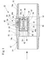
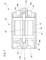
- FIG. 1 is a longitudinal sectional view of a flow sensor 10 of the present invention.
- FIG. 2 is a top view of the flow sensor 10 of FIG.
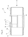
- FIG. 3 is a longitudinal sectional view of the flow sensor piping main body 12 of the flow sensor 10 of FIG.
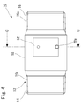
- FIG. 4 is a top view of the flow sensor pipe body 12 of FIG.
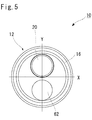
- FIG. 5 is an end view in the B direction of the flow sensor pipe main body 12 of FIG. 6 is a cross-sectional view taken along line CC of the flow sensor pipe main body 12 of FIG.
- FIG. 7 is an enlarged cross-sectional view of the flow sensor main body 24 of the flow sensor 10 of the present invention.
- FIG. 8 is an end view similar to FIG. 5 showing another embodiment of the flow sensor 10 of the present invention.
- FIG. 10 is a longitudinal sectional view of a conventional flow sensor disclosed in Patent Document 1.
- FIG. 11 is an end view of the flow sensor in FIG. 10 in the A direction.
- 12 is a partially enlarged cross-sectional view of FIG.
- FIG. 1 is a longitudinal sectional view of a flow sensor 10 of the present invention
- FIG. 2 is a top view of the flow sensor 10 of FIG. 1
- FIG. 5 is an end view in the B direction of the flow sensor pipe main body 12 of FIG. 3
- FIG. FIG. 7 is an enlarged sectional view of the flow sensor main body 24 of the flow sensor 10 of the present invention.
- reference numeral 10 indicates the flow sensor 10 of the present invention as a whole.
- the flow sensor 10 of the present invention includes a substantially circular pipe-shaped flow sensor pipe body 12 through which a fluid flows.
- the flow sensor pipe main body 12 includes an inlet side pipe section 14, an outlet side pipe section 16, and the inlet side pipe section 14 and the outlet side pipe section 16.
- a sensor housing 18 is provided.
- the inlet-side piping portion 14 and the outlet-side piping portion 16 of the flow sensor piping main body 12 are each provided with a female screw at an end thereof for connection with other connecting piping. 14a and a female screw 16a are formed. In this embodiment, the female screw 14a and the female screw 16a are formed. However, a known connecting portion such as a flange can be formed for connection with other connecting pipes.
- the sensor accommodating portion 18 of the flow sensor pipe main body 12 there is a flow sensor main body having a substantially cylindrical through hole in the fluid flow direction.
- the accommodating part 20 is formed.
- the flow sensor main body accommodating portion 20 is formed above the center line Y in the cross section of the sensor accommodating portion 18 of the flow sensor pipe main body 12. ing.
- the flow sensor main body accommodating portion 20 has a step portion 22 formed on the inner peripheral wall thereof on the inlet side piping portion 14 side. As shown in FIG. 1, the flow sensor main body 24 is disposed in the flow sensor main body accommodating portion 20 in the fluid flow direction.
- the flow sensor main body 24 includes a flow sensor unit 26 having the same configuration as the conventional flow sensor unit 126 shown in FIG.
- the vortex generating blade member 30 is configured integrally with the cylindrical casing 28, and the flow rate measuring rotary blade member 32 and the outlet member 34 are integrally stored in the cylindrical casing 28, and the flow sensor.
- the unit 26 is configured.
- a fixed vortex generating blade member 30 for generating a vortex is provided at the inlet 36 on the upstream side of the casing 28.
- the vortex generating blade member 30 is composed of a plurality (five in this embodiment) of blade members 38 formed in a spiral shape. Then, five vortex generation introduction paths 40 are formed spirally between the plurality of blade members 38 formed in this way.
- a flow rate measuring rotary blade member 32 that is rotated by the vortex generated by passing through the vortex generating introduction path 40 of the vortex generating blade member 30 is rotatably provided. Yes.
- a bearing 42 is formed at the center of the vortex generating blade member 30, and one end 44 a of the shaft portion 44 of the flow measurement rotating blade member 32 is attached to the bearing 42.
- an outlet member 34 for discharging the fluid that has passed through the flow measurement rotary blade member 32 is provided on the downstream side of the flow measurement rotary blade member 32.
- the outlet member 34 is formed with a plurality of outlets 34a for discharging fluid.
- a bearing 46 is formed at the center of the outlet member 34, and the other end 44 b of the shaft portion 44 of the flow rate measuring rotary blade member 32 is attached to the bearing 46.
- the flow measurement rotary blade member 32 is rotatably provided by being supported by the bearing 42 of the vortex generating blade member 30 and the bearing 46 of the outlet member 34.
- the rotary blade member 32 for flow rate measurement is provided with four blade portions 48 formed at a central angle of 90 ° and spaced apart from each other.
- the tips of these blade portions 48 are magnetized alternately to the S pole and the N pole, respectively.
- the flow sensor unit 26 is brought into contact with the stepped portion 22 formed on the inner peripheral wall of the flow sensor main body accommodating portion 20 on the vortex generating blade member 30 side, so that the outlet member 34.
- the flow sensor unit 26 is arranged inside the flow sensor main body accommodating portion 20.
- a rectangular recess 52 is formed in the side of the sensor housing portion 18 of the flow sensor pipe main body 12.
- a flow rate detector 54 that measures the flow rate by rotation of the rotary blade member 32 is provided.
- the flow rate detection unit 54 uses, for example, a Hall IC or the like as a pulse signal to detect a change in magnetic flux density or a change in the magnetic field direction due to the magnetized tip of the blade 48 as the flow measuring rotary blade member 32 rotates. As a result, the flow rate is measured.
- the flow rate detection unit 54 includes a substrate 56, and a Hall IC 58 is disposed on the substrate 56. A change in the direction of the magnetic field due to the magnetized tip of the blade 48 is detected by the Hall IC 58 along with the rotation of the flow rate measuring blade member 32, and a pulse signal is generated.
- the terminal 60 is connected to three wires: a common line (GND) 60a, an input power supply line (Vcc) 60b, and an output signal line (Vout) 60c.
- GND common line
- Vcc input power supply line
- Vout output signal line
- the substrate 56 is fixed to a screw hole 52a formed in the recess 52 with a set screw 56a.
- the one bypass flow path 62 is formed so that it may become a line symmetrical position.
- the relationship between the outer diameter R1 of the sensor housing part 18 of the flow sensor pipe body 12, the inner diameter R2 of the flow sensor body housing part 20, and the inner diameter R3 of the bypass flow path 62 is not particularly limited. It may be set as appropriate according to the intended use flow range and flow characteristics.
- the use flow rate in which the flow sensor body housing portion 20 and the bypass channel 62 are arranged, the cross-sectional shape, the number, and the placement position of the bypass channel 62 are also intended. What is necessary is just to set suitably according to a range and flow characteristics.
- the bypass channel 62 may be composed of a plurality of bypass channels.
- the bypass flow path 62 from the some bypass flow path 62, it is applicable to various use flow range and flow characteristics.
- the flow sensor main body 24 is disposed at the center of the cross section of the flow sensor pipe main body 12, and a plurality of bypass flow paths 62 are disposed around the flow sensor main body 24 at a predetermined interval. .
- the flow sensor main body 24 is disposed at the center of the cross section of the flow sensor pipe main body 12 and the plurality of bypass flow paths 62 are disposed around the flow sensor main body 24 at a predetermined interval, The pressure loss of the fluid flowing through the flow sensor main body 24 can be reduced, and accurate flow meter measurement is possible.
- the flow sensor main body 24 is disposed at the center of the cross section of the flow sensor pipe main body 12, and the three bypass flow paths 62 are spaced apart from each other by a certain distance around the flow sensor main body 24. They are spaced apart (90 ° center angle).
- the flow sensor main body 24 is disposed at the center of the cross section of the flow sensor pipe main body 12, and the two bypass flow paths 62 having a substantially partial ring shape in cross section are formed by the flow sensor.
- the main body 24 is disposed around the main body 24 at a predetermined interval (180 ° central angle).
- two bypass channels 62 having a substantially partial ring shape in cross section are formed along the inner periphery of the cross section of the flow sensor pipe main body 12.
- the arrangement position from the center of the cross section of the sensor pipe main body 12 can be changed as appropriate.
- the substantially partial ring-shaped bypass channel 62 is two bypass channels 62 in this embodiment, but this number may be one or three or more, and the arrangement center angle Etc. can be set as appropriate.
- the flow sensor main body 24 is connected to the cross section of the flow sensor pipe main body 12 as in the embodiment of FIGS. It is possible to dispose from the center, or to dispose at the center of the cross section of the flow sensor pipe main body 12.
- the outer diameter of the flow sensor pipe body 12 is reduced even if the flow passage cross-sectional area of the bypass passage 62 is the same as that of the flow sensor 10 of the embodiment of FIGS.
- the size can be reduced, the diameter can be reduced, and the design can be made compact.
- the flow sensor main body 24 is omitted.
- the flow sensor 10 of the present invention configured as described above is operated as follows.
- a part of the fluid introduced from the upstream-side inlet-side piping portion 14 of the flow sensor piping main body 12 is disposed in the flow sensor main body storage portion 20 in the sensor storage portion 18 of the flow sensor piping main body 12. It flows into the sensor body 24.
- the fluid flowing into the flow sensor main body 24 passes through the vortex generation introduction path 40 of the vortex generation blade member 30 to generate vortex.
- the flow measurement rotary blade member 32 is rotated by the vortex generated in this way, and the flow rate detection unit 54.
- the flow rate is output by outputting, as a pulse signal, fluctuations in magnetic flux density due to the magnetized tip of the blade part 48 or fluctuations in the magnetic field direction as the flow measurement rotary blade member 32 is rotated by a Hall IC or the like. It is configured to measure.
- the fluid that has passed through the flow rate measuring rotary blade member 32 is discharged to the outside from the outlet side piping portion 16 of the flow sensor piping main body 12 through the plurality of outlets 34 a of the outlet member 34. .
- the flow rate detection unit 54 includes a substrate 56, and a Hall IC 58 is disposed on the substrate 56. A change in the magnetic field direction due to the magnetized tip of the blade 48 is detected by the Hall IC 58 along with the rotation of the flow measurement rotating blade member 32 to generate a pulse signal.
- a part of the fluid flowing through the flow sensor pipe main body 12 is in the bypass flow path 62 formed in the flow direction of the fluid separately from the flow sensor main body storage section 20 in the sensor storage section 18 of the flow sensor pipe main body 12. Will flow.
- a flow sensor can be provided.
- the flow sensor main body 24 is not subjected to a high load, and the rotational speed of the flow rate measuring rotary blade member 32 does not increase. For this reason, wear damage does not occur in the bearings 42 and 46 and the protrusion 46a of the rotary blade member 32 for flow rate measurement, and an accurate flow meter can be measured, and the flow sensor 10 having a long product life can be provided.
- bypass passage 62 By changing the diameter and shape of the bypass passage 62, it can be applied to various flow ranges and flow characteristics, and the conventional existing flow sensor component (flow sensor unit 26) can be used as it is. In addition, it is possible to provide a flow sensor 10 that can reduce costs for design changes, molds, and the like, and can reduce costs. (Example 2)
- the bypass diameter 62 is set such that the outer diameter R1 of the sensor housing portion 18 of the flow sensor pipe body 12 is 45 mm and the inner diameter R2 of the flow sensor body housing portion 20 is 15 mm.
- the inner diameter R3 was changed to 15 mm, 12 mm, 10 mm, and 8 mm.
- the flow sensor 10 of the embodiment shown in FIG. 8B that is, the embodiment provided with two bypass channels 62 having a substantially partial ring shape corresponding to the inner diameter R3, 12 mm of the bypass channel 62 described above.
- the relationship between the flow rate of the fluid flowing through the flow sensor pipe body 12 and the pulse (number of rotations) detected by the flow sensor 10 of the present invention, that is, the measured flow rate was examined.
- the flow sensor main body 24 includes the flow sensor unit 26 including the vortex generating blade member 30, the flow rate measuring rotary blade member 32, and the outlet member 34.
- the flow sensor main body 24 has other configurations. Various modifications can be made without departing from the object of the present invention, such as application to the flow sensor main body 24.
- a flow sensor for measuring the flow rate of a fluid flowing in a pipe for example, a flow sensor for measuring the flow rate of a liquid fluid such as an instantaneous water heater, a boiler, a hot water supply facility, and an electric water heater.
Landscapes
- Physics & Mathematics (AREA)
- Fluid Mechanics (AREA)
- General Physics & Mathematics (AREA)
- Electromagnetism (AREA)
- Measuring Volume Flow (AREA)
Abstract
(課題)大流量を測定するために、流量が大幅に増加した場合にも従来の圧力センサに比較して圧力損失が小さくなり、フローセンサに高負荷がかかることがなく、流量測定用回転羽根部材の軸受けに摩耗損傷が生じず、正確な流量計の測定が可能で、製品寿命の長いフローセンサを提供する。 (解決手段)流体の流量を測定するためのフローセンサ10であって、流体が流れるフローセンサ配管本体12と、フローセンサ配管本体12に、流体の流れ方向に配設されたフローセンサ本体24と、フローセンサ配管本体12に、流体の流れ方向に配設されたバイパス流路62とを備える。
Description
本発明は、配管内を流れる流体の流量を測定するためのフローセンサ、例えば、瞬間湯沸かし器、ボイラー、給湯設備、電気温水器など、液体の流体の流量を測定するためのフローセンサに関する。
従来、このような流体の流量を測定するためのフローセンサとして、検出流量に応じたパルス信号を発生する形式のものが開発されている。このフローセンサは、例えば、瞬間湯沸器のフィードフォワード制御、バーナの着火制御などに使用されるほか、浴槽への積算流量、ボイラーなどの残湯量の検出用センサなどとして広く用いられている。
このような流体の流量を測定するためのフローセンサとしては、特許文献1(特開2001-255183号公報)に開示されている構造のフローセンサがある。
図10は、この特許文献1に開示されている従来のフローセンサの縦断面図、図11は、図10のフローセンサのA方向の端面図、図12は、図10の部分拡大断面図である。
この従来のフローセンサ100は、図10、図11に示したように、略円管形状のフローセンサ本体102を備えており、このフローセンサ本体102の上流側の入口104には、渦流を発生させる固定の渦流発生羽根部材106が設けられている。
また、図10、図11に示したように、渦流発生羽根部材106は、複数の(5枚の)螺旋状に形成された羽根部材108から構成されている。そして、このように形成された複数の羽根部材108の間に、螺旋状に5つの渦流発生導入路110が形成されている。
また、渦流発生羽根部材106の下流側には、渦流発生羽根部材106の渦流発生導入路110を通過することにより発生された渦流によって回転する流量測定用回転羽根部材112が回転可能に設けられている。
すなわち、渦流発生羽根部材106の中央に軸受け114が形成されており、この軸受け114に、流量測定用回転羽根部材112の軸部116の一方の端部116aが装着されている。
さらに、この流量測定用回転羽根部材112の下流側には、この流量測定用回転羽根部材112を通過した流体を排出するための出口部材118が設けられている。この出口部材118には、流体を排出するための複数の出口118aが形成されている。
また、この出口部材118の中央に軸受け120が形成されており、この軸受け120に、流量測定用回転羽根部材112の軸部116の他方の端部116bが装着されている。
このよう構成することによって、渦流発生羽根部材106の軸受け114、出口部材118の軸受け120に軸支されて、流量測定用回転羽根部材112が回転可能に設けられている。
さらに、図10、図11に示したように、流量測定用回転羽根部材112は、4枚の中心角度90°で相互に離間して形成された羽根部140が設けられている。これらの羽根部140の先端は、それぞれ交互にS極とN極に磁化されている。
また、フローセンサ本体102の側部に形成した凹部102aには、流量測定用回転羽根部材112の回転によって、流量測定を行う流量検知部122を備えている。
この流量検知部122は、例えば、ホールICなどにより、流量測定用回転羽根部材112の回転に伴って、羽根部140の磁化された先端による磁束密度の変動、または、磁界方向の変動をパルス信号として出力することによって流量を測定するように構成されている。
なお、渦流発生羽根部材106は、円筒形状のケーシング124と一体で構成され、これらの流量測定用回転羽根部材112、出口部材118が、円筒形状のケーシング124内に一体的に収納され、フローセンサユニット126を構成している。
そして、このフローセンサユニット126を、フローセンサ本体102に形成された入口側の段部102bに、渦流発生羽根部材106側を当接させて、出口部材118側を固定リング128で固定することによって、フローセンサ本体102の内部にフローセンサユニット126を配置するように構成されている。
このように構成される従来のフローセンサ100では、フローセンサ本体102の上流側の入口104から導入された流体が、渦流発生羽根部材106の渦流発生導入路110を通過することにより渦流が発生される。
そして、このように発生された渦流によって、流量測定用回転羽根部材112が回転し、流量検知部122によって、例えば、ホールICなどにより、流量測定用回転羽根部材112の回転に伴って、羽根部140の磁化された先端による磁束密度の変動、または、磁界方向の変動をパルス信号として出力することによって流量を測定するように構成されている。
さらに、この流量測定用回転羽根部材112を通過した流体は、出口部材118の複数の出口118aを介して、外部に排出されるようになっている。
具体的には、流量検知部122は、図10に示したように、基板130を備えており、この基板130にホールIC132が配設されている。そして、流量測定用回転羽根部材112の回転に伴って、羽根部140の磁化された先端による磁界方向の変化を、ホールIC132により検出してパルス信号を発生するように構成されている。
すなわち、ホールIC132に直流定格電圧を、端子134を介して印加しておくことにより、流量測定用回転羽根部材112の回転数(流量)に応じた周波数の電圧が、端子134を介して出力されるようになっている。
なお、図10中、符号136は、流量検知部122の基板130、ホールIC132などを封止する封止樹脂を、符号138は、リード線を、符号142は、取り出しハウジングをそれぞれ示している。
また、端子134は、図10に示したように、共通線(GND)134a、入力電源線(Vcc)134b、出力信号線(Vout)134cの3本の電線と接続されている。
しかしながら、このような従来のフローセンサ100では、大流量を流す際、圧力損失が大きくなってしまう。このため、システム上、一次圧力を高く設計しなければならなくなるため、圧力損失が小さい方が好ましい。
また、このように大流量を測定するために、流量が大幅に増加した場合には、流量測定用回転羽根部材112の回転数が大きくなる。
このために、流量測定用回転羽根部材112の軸部116の端部116bが、出口部材118に設けられた軸受け120において磨耗損傷して、製品寿命が短くなってしまうことがある。
すなわち、図12(A)の拡大図に示したように、出口部材118に設けられた軸受け120には、流量測定用回転羽根部材112の軸部116との接触面積を低減(摩擦抵抗を低減)するために、突設された突部120aが設けられている。
しかしながら、上記のように流量が大幅に増加した場合には、流量測定用回転羽根部材112の回転数が大きくなり、流量測定用回転羽根部材112の回転によって、突部120aが磨耗損傷することがある。
これにより、図12(B)の拡大図の矢印Dに示したように、流量測定用回転羽根部材112の軸部116の端部116bが、出口部材118に設けられた軸受け120の端面120bまで侵入して、摩擦抵抗が大きくなってしまい、正確な流量の測定ができないことになり、製品寿命が短くなってしまう。
本発明は、このような現状に鑑み、大流量を測定するために、流量が大幅に増加した場合にも、従来の圧力センサに比較して圧力損失が小さく、フローセンサに高負荷がかかることがなく、正確な流量計の測定が可能で、製品寿命の長いフローセンサを提供することを目的とする。
また、本発明は、流量の大流量を測定するために、流量が大幅に増加した場合にも、従来の圧力センサに比較して圧力損失が小さく、フローセンサに高負荷がかかることがなく、例えば、流量測定用回転羽根部材の軸受けに摩耗損傷が生じず、正確な流量計の測定が可能で、製品寿命の長いフローセンサを提供することを目的とする。
また、本発明は、様々な使用流量範囲、流量特性に適用可能で、しかも、従来の既存のフローセンサの部品をそのまま使用することができ、設計変更、金型などにかかる費用を低減でき、コストも低減できるフローセンサを提供することを目的とする。
本発明は、前述したような従来技術における課題及び目的を達成するために発明されたものであって、本発明のフローセンサは、
流体の流量を測定するためのフローセンサであって、
前記流体が流れるフローセンサ配管本体と、
前記フローセンサ配管本体に、流体の流れ方向に配設されたフローセンサ本体と、
前記フローセンサ配管本体に、流体の流れ方向に配設されたバイパス流路とを備えることを特徴とする。
流体の流量を測定するためのフローセンサであって、
前記流体が流れるフローセンサ配管本体と、
前記フローセンサ配管本体に、流体の流れ方向に配設されたフローセンサ本体と、
前記フローセンサ配管本体に、流体の流れ方向に配設されたバイパス流路とを備えることを特徴とする。
このように構成することによって、フローセンサ配管本体を流れる流体の一部が、フローセンサ配管本体に、流体の流れ方向に配設されたバイパス流路内を流れることになる。
これにより、フローセンサ配管本体を流れる流体のうち、フローセンサ本体を流れる流体の流量が低減することになる。
従って、大流量を測定しようとする場合にも、従来の圧力センサに比較して圧力損失が小さくなる。また、流量が大幅に増加した場合にも、フローセンサ本体に高負荷がかからず、フローセンサ本体が磨耗損傷することがなく、正確な流量計の測定が可能で、製品寿命の長いフローセンサを提供することができる。
さらに、バイパス流路の口径、形状を変えることによって、様々な使用流量範囲、流量特性に適用可能である。
また、本発明のフローセンサは、
前記フローセンサ本体が、
前記フローセンサ本体の前記流体の上流側入口に配設され、渦流を発生させる固定の渦流発生羽根部材と、
前記渦流発生羽根部材の下流側に配設され、前記渦流発生羽根部材により発生された渦流によって回転する流量測定用回転羽根部材と、
前記流量測定用回転羽根部材の軸部を軸支する軸受けと、
前記流量測定用回転羽根部材の回転によって、流量測定を行う流量検知部を備えることを特徴とする。
前記フローセンサ本体が、
前記フローセンサ本体の前記流体の上流側入口に配設され、渦流を発生させる固定の渦流発生羽根部材と、
前記渦流発生羽根部材の下流側に配設され、前記渦流発生羽根部材により発生された渦流によって回転する流量測定用回転羽根部材と、
前記流量測定用回転羽根部材の軸部を軸支する軸受けと、
前記流量測定用回転羽根部材の回転によって、流量測定を行う流量検知部を備えることを特徴とする。
このように構成することによって、フローセンサ配管本体を流れる流体の一部が、フローセンサ配管本体に、流体の流れ方向に配設されたバイパス流路内を流れることになる。
これにより、フローセンサ配管本体を流れる流体のうち、フローセンサ本体を流れる流体の流量が低減することになる。
従って、大流量を測定しようとする場合にも、従来の圧力センサに比較して圧力損失が小さくなる。
また、流量が大幅に増加した場合にも、フローセンサ本体に高負荷がかからず、流量測定用回転羽根部材の回転数が大きくならない。このため、流量測定用回転羽根部材の軸受けに摩耗損傷が生じず、正確な流量計の測定が可能で、製品寿命の長いフローセンサを提供することができる。
また、バイパス流路の口径、形状を変えることによって、様々な使用流量範囲、流量特性に適用可能で、しかも、従来の既存のフローセンサの部品をそのまま使用することができ、設計変更、金型などにかかる費用を低減でき、コストも低減できるフローセンサを提供することができる。
また、本発明のフローセンサは、前記バイパス流路が、複数のバイパス流路から構成されていることを特徴とする。
このようにバイパス流路が、複数のバイパス流路から構成することによって、様々な使用流量範囲、流量特性に適用可能である。
また、本発明のフローセンサは、
前記フローセンサ本体が、前記フローセンサ配管本体の断面中央に配設され、
前記複数のバイパス流路が、前記フローセンサ本体の周囲に一定間隔離間して配設されていることを特徴とする。
前記フローセンサ本体が、前記フローセンサ配管本体の断面中央に配設され、
前記複数のバイパス流路が、前記フローセンサ本体の周囲に一定間隔離間して配設されていることを特徴とする。
このように、フローセンサ本体が、フローセンサ配管本体の断面中央に配設され、複数のバイパス流路が、フローセンサ本体の周囲に一定間隔離間して配設されていれば、フローセンサ本体を流れる流体の圧力損失を低減することができる。
さらに、フローセンサ本体として従来のものを使用でき、例えば、通水耐久試験などを利用できるので、設計の時間を節約できるとともに、フローセンサ本体収容部とバイパス流路が形成されたフローセンサ配管本体を準備すれば良いので、コストを低減することができる。
また、本発明のフローセンサは、前記バイパス流路が、断面形状が略部分リング形状のバイパス流路であることを特徴とする。
このように構成することによって、バイパス流路が、断面形状が略部分リング形状のバイパス流路であれば、バイパス流路62の流路断面積が同じでも、フローセンサ配管本体12の外径を小さくすることができ、小径化が可能でコンパクトな設計とすることができる。
本発明によれば、フローセンサ配管本体を流れる流体の一部が、フローセンサ配管本体に、流体の流れ方向に配設されたバイパス流路内を流れることになる。
これにより、フローセンサ配管本体を流れる流体のうち、フローセンサ本体を流れる流体の流量が低減することになる。
従って、大流量を測定しようとする場合にも、従来の圧力センサに比較して圧力損失が小さくなる。また、流量が大幅に増加した場合にも、フローセンサ本体に高負荷がかからず、フローセンサ本体が磨耗損傷することがなく、正確な流量計の測定が可能で、製品寿命の長いフローセンサを提供することができる。
さらに、バイパス流路の口径、形状を変えることによって、様々な使用流量範囲、流量特性に適用可能である。
また、流量が大幅に増加した場合にも、フローセンサ本体に高負荷がかからず、流量測定用回転羽根部材の回転数が大きくならない。このため、流量測定用回転羽根部材の軸受けに摩耗損傷が生じず、正確な流量計の測定が可能で、製品寿命の長いフローセンサを提供することができる。
また、バイパス流路の口径、形状を変えることによって、様々な使用流量範囲、流量特性に適用可能で、しかも、従来の既存のフローセンサの部品をそのまま使用することができ、設計変更、金型などにかかる費用を低減でき、コストも低減できるフローセンサを提供することができる。
以下、本発明の実施の形態(実施例)を図面に基づいてより詳細に説明する。
(実施例1)
(実施例1)
図1は、本発明のフローセンサ10の縦断面図、図2は、図1のフローセンサ10の上面図、図3は、図1のフローセンサ10のフローセンサ配管本体12の縦断面図、図4は、図3のフローセンサ配管本体12の上面図、図5は、図3のフローセンサ配管本体12のB方向の端面図、図6は、図4のフローセンサ配管本体12のC-C線での断面図、図7は、本発明のフローセンサ10のフローセンサ本体24の拡大断面図である。
図1、図2において、符号10は、全体で本発明のフローセンサ10を示している。
図1、図2に示したように、本発明のフローセンサ10は、流体が流れる略円管形状のフローセンサ配管本体12を備えている。このフローセンサ配管本体12は、図1~図4に示したように、入口側配管部14と、出口側配管部16と、これらの入口側配管部14と出口側配管部16との間に設けられたセンサ収容部18を備えている。
また、この実施例のフローセンサ10では、フローセンサ配管本体12の入口側配管部14、出口側配管部16には、他の接続配管との接続のために、それぞれその端部に、雌ネジ14a、雌ネジ16aが形成されている。なお、この実施例では、雌ネジ14a、雌ネジ16aを形成したが、他の接続配管との接続のために、フランジなどの公知の接続部を形成することも可能である。
図1、図3、図5~図6に示したように、フローセンサ配管本体12のセンサ収容部18にはその内部に、流体の流れ方向に、略円筒形状の貫通孔からなるフローセンサ本体収容部20が形成されている。
すなわち、図5~図6に示したように、この実施例では、フローセンサ配管本体12のセンサ収容部18の断面において、中心線Y上の上方よりに、フローセンサ本体収容部20が形成されている。
また、このフローセンサ本体収容部20には、その内周壁に、入口側配管部14側に段部22が形成されている。そして、図1に示したように、このフローセンサ本体収容部20に、流体の流れ方向にフローセンサ本体24が配設されている。
図7に示したように、フローセンサ本体24は、図10に示した従来のフローセンサユニット126と同様な構成のフローセンサユニット26から構成されている。
すなわち、渦流発生羽根部材30は、円筒形状のケーシング28と一体で構成され、これらの流量測定用回転羽根部材32、出口部材34が、円筒形状のケーシング28内に一体的に収納され、フローセンサユニット26を構成している。
そして、ケーシング28の上流側の入口36には、渦流を発生させる固定の渦流発生羽根部材30が設けられている。
また、図7に示したように、渦流発生羽根部材30は、複数の(この実施例では5枚の)螺旋状に形成された羽根部材38から構成されている。そして、このように形成された複数の羽根部材38の間に、螺旋状に5つの渦流発生導入路40が形成されている。
また、渦流発生羽根部材30の下流側には、渦流発生羽根部材30の渦流発生導入路40を通過することにより発生された渦流によって回転する流量測定用回転羽根部材32が回転可能に設けられている。
すなわち、渦流発生羽根部材30の中央に軸受け42が形成されており、この軸受け42に、流量測定用回転羽根部材32の軸部44の一方の端部44aが装着されている。
さらに、この流量測定用回転羽根部材32の下流側には、この流量測定用回転羽根部材32を通過した流体を排出するための出口部材34が設けられている。この出口部材34には、流体を排出するための複数の出口34aが形成されている。
また、この出口部材34の中央に軸受け46が形成されており、この軸受け46に、流量測定用回転羽根部材32の軸部44の他方の端部44bが装着されている。
このように構成することによって、渦流発生羽根部材30の軸受け42、出口部材34の軸受け46に軸支されて、流量測定用回転羽根部材32が回転可能に設けられている。
さらに、図7に示したように、流量測定用回転羽根部材32は、4枚の中心角度90°で相互に離間して形成された羽根部48が設けられている。これらの羽根部48の先端は、それぞれ交互にS極とN極に磁化されている。
そして、図1に示したように、このフローセンサユニット26を、フローセンサ本体収容部20の内周壁に形成された段部22に、渦流発生羽根部材30側を当接させて、出口部材34側を固定リング50で固定することによって、フローセンサ本体収容部20の内部にフローセンサユニット26を配置するように構成されている。
一方、図1~図4、図6に示したように、フローセンサ配管本体12のセンサ収容部18の側部には、矩形形状の凹部52が形成されており、凹部52には、流量測定用回転羽根部材32の回転によって、流量測定を行う流量検知部54を備えている。
この流量検知部54は、例えば、ホールICなどにより、流量測定用回転羽根部材32の回転に伴って、羽根部48の磁化された先端による磁束密度の変動、または、磁界方向の変動をパルス信号として出力することによって流量を測定するように構成されている。
具体的には、流量検知部54は、図1、図2に示したように、基板56を備えており、この基板56にホールIC58が配設されている。そして、流量測定用回転羽根部材32の回転に伴って、羽根部48の磁化された先端による磁界方向の変化を、ホールIC58により検出してパルス信号を発生するように構成されている。
すなわち、ホールIC58に直流定格電圧を、端子60を介して印加しておくことにより、流量測定用回転羽根部材32の回転数(流量)に応じた周波数の電圧が、端子60を介して出力されるようになっている。
なお、端子60は、図2に示したように、共通線(GND)60a、入力電源線(Vcc)60b、出力信号線(Vout)60cの3本の電線と接続されている。
また、基板56は、図1、図2、図6に示したように、凹部52に形成されたネジ穴52aに、止めネジ56aで固定されるようになっている。
一方、図1、図3、図5~図6に示したように、フローセンサ配管本体12のセンサ収容部18にはその内部に、フローセンサ本体収容部20とは別に、流体の流れ方向に、略円筒形状の貫通孔からなるバイパス流路62が形成されている。
この実施例の場合には、図5、図6に示したように、フローセンサ配管本体12のセンサ収容部18の断面において、中心線Y上の下方よりに、フローセンサ本体収容部20と中心線Xについて、線対称の位置となるように、1個のバイパス流路62が形成されている。
なお、この場合、フローセンサ配管本体12のセンサ収容部18の外径R1と、フローセンサ本体収容部20の内径R2と、バイパス流路62の内径R3との関係は、特に限定されるものではなく、目的とする使用流量範囲、流量特性に応じて適宜設定すれば良い。
また、フローセンサ配管本体12のセンサ収容部18の断面において、フローセンサ本体収容部20とバイパス流路62の配置位置、バイパス流路62の断面形状、数、配置位置なども目的とする使用流量範囲、流量特性に応じて適宜設定すれば良い。
例えば、図8に示したように、バイパス流路62が、複数のバイパス流路から構成されていても良い。このようにバイパス流路62が、複数のバイパス流路62から構成することによって、様々な使用流量範囲、流量特性に適用可能である。
すなわち、図8では、フローセンサ本体24が、フローセンサ配管本体12の断面中央に配設され、複数のバイパス流路62が、フローセンサ本体24の周囲に一定間隔離間して配設されている。
このように、フローセンサ本体24が、フローセンサ配管本体12の断面中央に配設され、複数のバイパス流路62が、フローセンサ本体24の周囲に一定間隔離間して配設されていれば、フローセンサ本体24を流れる流体の圧力損失を低減することができ、正確な流量計の測定が可能である。
例えば、図8(A)の実施例では、フローセンサ本体24が、フローセンサ配管本体12の断面中央に配設され、3個のバイパス流路62が、フローセンサ本体24の周囲に一定間隔離間(90°の中心角度)離間して配設されている。
また、図8(B)の実施例では、フローセンサ本体24が、フローセンサ配管本体12の断面中央に配設され、断面形状が略部分リング形状の2個のバイパス流路62が、フローセンサ本体24の周囲に一定間隔離間(180°の中心角度)離間して配設されている。
この図8(B)の実施例では、フローセンサ配管本体12の断面内周に沿って、断面形状が略部分リング形状の2個のバイパス流路62を形成したが、バイパス流路62のフローセンサ配管本体12の断面中心からの配置位置は適宜変更することができる。
なお、この場合、略部分リング形状のバイパス流路62を、この実施例では、2個のバイパス流路62としたが、この数は1個でも、3個以上でも良く、また、配置中心角度などは適宜設定することができる。
また、1個の略部分リング形状のバイパス流路62を配置する場合には、図示しないが、図1~図7の実施例のように、フローセンサ本体24を、フローセンサ配管本体12の断面中心からずらして配設することも、また、フローセンサ配管本体12の断面中央に配設することも可能である。
この図8(B)の実施例では、図1~図7の実施例のフローセンサ10に比較して、バイパス流路62の流路断面積が同じでも、フローセンサ配管本体12の外径を小さくすることができ、小径化が可能でコンパクトな設計とすることができる。
なお、図8は、説明の便宜上、フローセンサ本体24を省略して示している。
なお、図8は、説明の便宜上、フローセンサ本体24を省略して示している。
このように構成される本発明のフローセンサ10は、以下のように作動される。
先ず、フローセンサ配管本体12の上流側の入口側配管部14から導入された流体の一部が、フローセンサ配管本体12のセンサ収容部18において、フローセンサ本体収容部20に配設されたフローセンサ本体24内に流入する。
そして、フローセンサ本体24内に流入した流体は、渦流発生羽根部材30の渦流発生導入路40を通過することにより渦流が発生される。
このように発生された渦流によって、流量測定用回転羽根部材32が回転し、流量検知部54によって。例えば、ホールICなどにより、流量測定用回転羽根部材32の回転に伴って、羽根部48の磁化された先端による磁束密度の変動、または、磁界方向の変動をパルス信号として出力することによって流量を測定するように構成されている。
さらに、この流量測定用回転羽根部材32を通過した流体は、出口部材34の複数の出口34aを介して、フローセンサ配管本体12の出口側配管部16から外部に排出されるようになっている。
具体的には、流量検知部54は、図1、図2に示したように、基板56を備えており、この基板56にホールIC58が配設されている。そして、流量測定用回転羽根部材32の回転に伴って、羽根部48の磁化された先端による磁界方向の変化を、ホールIC58により検出してパルス信号を発生する。
すなわち、ホールIC58に直流定格電圧を、端子60を介して印加しておくことにより、流量測定用回転羽根部材32の回転数(流量)に応じた周波数の電圧が、端子60を介して出力されるようになっている。これによって、フローセンサ配管本体12を流れる流体の流量が測定されるようになっている。
一方、フローセンサ配管本体12を流れる流体の一部が、フローセンサ配管本体12のセンサ収容部18に、フローセンサ本体収容部20とは別に、流体の流れ方向に形成されたバイパス流路62内を流れることになる。
これにより、フローセンサ配管本体12を流れる流体のうち、フローセンサ本体24を流れる流体の流量が低減することになる。
従って、大流量を測定しようとする場合にも、従来の圧力センサに比較して圧力損失が小さくなる。また、流量が大幅に増加した場合にも、フローセンサ本体24に高負荷がかからず、フローセンサ本体24が磨耗損傷することがなく、正確な流量計の測定が可能で、製品寿命の長いフローセンサを提供することができる。
また、流量が大幅に増加した場合にも、フローセンサ本体24に高負荷がかからず、流量測定用回転羽根部材32の回転数が大きくならない。このため、流量測定用回転羽根部材32の軸受け42、46、突部46aに摩耗損傷が生じず、正確な流量計の測定が可能で、製品寿命の長いフローセンサ10を提供することができる。
また、バイパス流路62の口径、形状を変えることによって、様々な使用流量範囲、流量特性に適用可能で、しかも、従来の既存のフローセンサの部品(フローセンサユニット26)をそのまま使用することができ、設計変更、金型などにかかる費用を低減でき、コストも低減できるフローセンサ10を提供することができる。
(実施例2)
(実施例2)
図1~図7に示した実施例のフローセンサ10において、フローセンサ配管本体12のセンサ収容部18の外径R1を45mm、フローセンサ本体収容部20の内径R2を15mmとして、バイパス流路62の内径R3を、15mm、12mm、10mm、8mmに変化させた。これらについて、フローセンサ配管本体12に流した流体の流量と、本発明のフローセンサ10で検出されたパルス(回転数)、すなわち、測定流量との関係を調べた。
また、図8(B)に示した実施例のフローセンサ10、すなわち、上記のバイパス流路62の内径R3、12mmに相当する、略部分リング形状の2個のバイパス流路62を備えた実施例について、フローセンサ配管本体12に流した流体の流量と、本発明のフローセンサ10で検出されたパルス(回転数)、すなわち、測定流量との関係を調べた。
その結果を、図9のグラフに示した。図9のグラフからも明らかなように、本発明のフローセンサ10によれば、いずれもリニアな関係が得られ、バイパス流路62の断面形状、寸法、数、配置位置などを変更することによって、目的とする使用流量範囲、流量特性に応じたフローセンサ10を提供することができることが分かる。
以上、本発明の好ましい実施の態様を説明してきたが、本発明はこれに限定されることはない。
また、上記実施例では、フローセンサ本体24として、渦流発生羽根部材30、流量測定用回転羽根部材32、出口部材34からなるフローセンサユニット26から構成したが、フローセンサ本体24として、その他の構成のフローセンサ本体24に適用することも可能であるなど本発明の目的を逸脱しない範囲で種々の変更が可能である。
配管内を流れる流体の流量を測定するためのフローセンサ、例えば、瞬間湯沸かし器、ボイラー、給湯設備、電気温水器など、液体の流体の流量を測定するためのフローセンサに適用することができる。
10 フローセンサ
12 フローセンサ配管本体
14 入口側配管部
14a 雌ネジ
16 出口側配管部
16a 雌ネジ
18 センサ収容部
20 フローセンサ本体収容部
22 段部
24 フローセンサ本体
26 フローセンサユニット
28 ケーシング
30 渦流発生羽根部材
32 流量測定用回転羽根部材
34 出口部材
34a 出口
36 入口
38 羽根部材
40 渦流発生導入路
42 軸受け
44 軸部
44a 端部
44b 端部
46 軸受け
46a 突部
48 羽根部
50 固定リング
52 凹部
52a ネジ穴
54 流量検知部
56 基板
56a ネジ
58 ホールIC
60 端子
62 バイパス流路
100 フローセンサ
102 フローセンサ本体
102a 凹部
102b 段部
104 入口
106 渦流発生羽根部材
108 羽根部材
110 渦流発生導入路
112 流量測定用回転羽根部材
114 軸受け
116 軸部
116a 端部
116b 端部
118 出口部材
118a 出口
120 軸受け
120a 突部
120b 端面
122 流量検知部
124 ケーシング
126 フローセンサユニット
128 固定リング
130 基板
132 ホールIC
134 端子
136 封止樹脂
138 リード線
140 羽根部
142 取り出しハウジング
R1 内径
R2 内径
R3 内径
X 中心線
Y 中心線
12 フローセンサ配管本体
14 入口側配管部
14a 雌ネジ
16 出口側配管部
16a 雌ネジ
18 センサ収容部
20 フローセンサ本体収容部
22 段部
24 フローセンサ本体
26 フローセンサユニット
28 ケーシング
30 渦流発生羽根部材
32 流量測定用回転羽根部材
34 出口部材
34a 出口
36 入口
38 羽根部材
40 渦流発生導入路
42 軸受け
44 軸部
44a 端部
44b 端部
46 軸受け
46a 突部
48 羽根部
50 固定リング
52 凹部
52a ネジ穴
54 流量検知部
56 基板
56a ネジ
58 ホールIC
60 端子
62 バイパス流路
100 フローセンサ
102 フローセンサ本体
102a 凹部
102b 段部
104 入口
106 渦流発生羽根部材
108 羽根部材
110 渦流発生導入路
112 流量測定用回転羽根部材
114 軸受け
116 軸部
116a 端部
116b 端部
118 出口部材
118a 出口
120 軸受け
120a 突部
120b 端面
122 流量検知部
124 ケーシング
126 フローセンサユニット
128 固定リング
130 基板
132 ホールIC
134 端子
136 封止樹脂
138 リード線
140 羽根部
142 取り出しハウジング
R1 内径
R2 内径
R3 内径
X 中心線
Y 中心線
Claims (5)
- 流体の流量を測定するためのフローセンサであって、
前記流体が流れるフローセンサ配管本体と、
前記フローセンサ配管本体に、流体の流れ方向に配設されたフローセンサ本体と、
前記フローセンサ配管本体に、流体の流れ方向に配設されたバイパス流路とを備えることを特徴とするフローセンサ。 - 前記フローセンサ本体が、
前記フローセンサ本体の前記流体の上流側入口に配設され、渦流を発生させる固定の渦流発生羽根部材と、
前記渦流発生羽根部材の下流側に配設され、前記渦流発生羽根部材により発生された渦流によって回転する流量測定用回転羽根部材と、
前記流量測定用回転羽根部材の軸部を軸支する軸受けと、
前記流量測定用回転羽根部材の回転によって、流量測定を行う流量検知部を備えることを特徴とする請求項1に記載のフローセンサ。 - 前記バイパス流路が、複数のバイパス流路から構成されていることを特徴とする請求項1から2のいずれかに記載のフローセンサ。
- 前記フローセンサ本体が、前記フローセンサ配管本体の断面中央に配設され、
前記複数のバイパス流路が、前記フローセンサ本体の周囲に一定間隔離間して配設されていることを特徴とする請求項3に記載のフローセンサ。 - 前記バイパス流路が、断面形状が略部分リング形状のバイパス流路であることを特徴とする請求項1から4のいずれかに記載のフローセンサ。
Priority Applications (1)
| Application Number | Priority Date | Filing Date | Title |
|---|---|---|---|
| EP15812478.4A EP3163261B1 (en) | 2014-06-27 | 2015-02-25 | Flow sensor |
Applications Claiming Priority (2)
| Application Number | Priority Date | Filing Date | Title |
|---|---|---|---|
| JP2014133286A JP5955351B2 (ja) | 2014-06-27 | 2014-06-27 | フローセンサ |
| JP2014-133286 | 2014-06-27 |
Publications (1)
| Publication Number | Publication Date |
|---|---|
| WO2015198633A1 true WO2015198633A1 (ja) | 2015-12-30 |
Family
ID=54937736
Family Applications (1)
| Application Number | Title | Priority Date | Filing Date |
|---|---|---|---|
| PCT/JP2015/055363 Ceased WO2015198633A1 (ja) | 2014-06-27 | 2015-02-25 | フローセンサ |
Country Status (3)
| Country | Link |
|---|---|
| EP (1) | EP3163261B1 (ja) |
| JP (1) | JP5955351B2 (ja) |
| WO (1) | WO2015198633A1 (ja) |
Citations (1)
| Publication number | Priority date | Publication date | Assignee | Title |
|---|---|---|---|---|
| JPH0687820U (ja) * | 1993-06-08 | 1994-12-22 | シーケーディ株式会社 | 流量センサ |
Family Cites Families (9)
| Publication number | Priority date | Publication date | Assignee | Title |
|---|---|---|---|---|
| GB984941A (en) * | 1963-02-16 | 1965-03-03 | Glacier Co Ltd | Rotary fluid-flow measuring devices |
| JPS58125823U (ja) * | 1982-02-17 | 1983-08-26 | トキコ株式会社 | 流量計 |
| JPS5984115A (ja) * | 1982-11-05 | 1984-05-15 | Nissan Motor Co Ltd | 流量測定装置 |
| JP2938228B2 (ja) * | 1991-06-28 | 1999-08-23 | リコーエレメックス株式会社 | 軸流式水道メータ |
| US6481293B1 (en) * | 1997-03-19 | 2002-11-19 | Osmonics, Inc. | Elbow mounted turbine flowmeter |
| DE19815658A1 (de) * | 1998-04-08 | 1999-10-14 | Bosch Gmbh Robert | Vorrichtung zum Messen der Masse eines strömenden Mediums |
| JP2001255183A (ja) * | 2000-03-13 | 2001-09-21 | Saginomiya Seisakusho Inc | フローセンサ |
| DE102009060516A1 (de) * | 2009-12-23 | 2011-06-30 | Gebr.Kemper GmbH + Co.KG Metallwerke, 57462 | Durchflussmengenmessapparatur für Flüssigkeiten |
| DE102011110023A1 (de) * | 2011-08-11 | 2013-02-14 | Hydrometer Gmbh | Woltmannzähler |
-
2014
- 2014-06-27 JP JP2014133286A patent/JP5955351B2/ja not_active Expired - Fee Related
-
2015
- 2015-02-25 WO PCT/JP2015/055363 patent/WO2015198633A1/ja not_active Ceased
- 2015-02-25 EP EP15812478.4A patent/EP3163261B1/en active Active
Patent Citations (1)
| Publication number | Priority date | Publication date | Assignee | Title |
|---|---|---|---|---|
| JPH0687820U (ja) * | 1993-06-08 | 1994-12-22 | シーケーディ株式会社 | 流量センサ |
Also Published As
| Publication number | Publication date |
|---|---|
| JP2016011879A (ja) | 2016-01-21 |
| JP5955351B2 (ja) | 2016-07-20 |
| EP3163261A1 (en) | 2017-05-03 |
| EP3163261B1 (en) | 2020-04-01 |
| EP3163261A4 (en) | 2018-01-17 |
Similar Documents
| Publication | Publication Date | Title |
|---|---|---|
| US7213467B2 (en) | Flowmeter | |
| CN107735652B (zh) | 包括测量通道和副通道的流量计 | |
| CN105814412A (zh) | 电磁流量计 | |
| KR20150098586A (ko) | 차압식 유량계 및 그것을 구비한 유량 컨트롤러 | |
| EP2824428A1 (en) | Coaxial flow meter | |
| JP6235986B2 (ja) | フローセンサ | |
| KR200437952Y1 (ko) | 정류기를 구비한 수도계량기 | |
| JP5955351B2 (ja) | フローセンサ | |
| US9175990B2 (en) | Axial-flow type impedance water flow sensor | |
| JP2013170912A (ja) | 流量センサ | |
| JP2003166861A (ja) | タービン式流量計 | |
| JP2005257309A (ja) | タービン流量計及び流体回転機械 | |
| KR20020076418A (ko) | 터빈 유량계 | |
| ITUB20155897A1 (it) | Dispositivo per la misurazione e/o il controllo volumetrico di un fluido | |
| RU2337319C1 (ru) | Тангенциальный турбинный расходомер | |
| US11408757B2 (en) | Flow meter device according to the vortex measuring principle, measuring tube for same, and method for measuring the flow rate or the flow speed of a medium | |
| KR100400405B1 (ko) | 터빈 유량계 | |
| ATE474210T1 (de) | Messkapsel für flüssigkeitszähler und flüssigkeitszähler | |
| JP6435537B2 (ja) | 検出ユニット | |
| KR102615908B1 (ko) | 임펠러식 역과방지 유량계 | |
| EP4025879B1 (en) | Axial flowmeter | |
| JP2018031787A (ja) | フローセンサ | |
| JP2009216663A (ja) | 流量計 | |
| ZA200208941B (en) | Flowmeter. | |
| KR100732117B1 (ko) | 유량 검출기 |
Legal Events
| Date | Code | Title | Description |
|---|---|---|---|
| 121 | Ep: the epo has been informed by wipo that ep was designated in this application |
Ref document number: 15812478 Country of ref document: EP Kind code of ref document: A1 |
|
| REEP | Request for entry into the european phase |
Ref document number: 2015812478 Country of ref document: EP |
|
| WWE | Wipo information: entry into national phase |
Ref document number: 2015812478 Country of ref document: EP |
|
| NENP | Non-entry into the national phase |
Ref country code: DE |