WO2015198668A1 - 採取部及びバイオセンサ - Google Patents
採取部及びバイオセンサ Download PDFInfo
- Publication number
- WO2015198668A1 WO2015198668A1 PCT/JP2015/058903 JP2015058903W WO2015198668A1 WO 2015198668 A1 WO2015198668 A1 WO 2015198668A1 JP 2015058903 W JP2015058903 W JP 2015058903W WO 2015198668 A1 WO2015198668 A1 WO 2015198668A1
- Authority
- WO
- WIPO (PCT)
- Prior art keywords
- receiving
- substance
- sampling
- receiving part
- receiving portion
- Prior art date
- Legal status (The legal status is an assumption and is not a legal conclusion. Google has not performed a legal analysis and makes no representation as to the accuracy of the status listed.)
- Ceased
Links
Images

Classifications
-
- G—PHYSICS
- G01—MEASURING; TESTING
- G01N—INVESTIGATING OR ANALYSING MATERIALS BY DETERMINING THEIR CHEMICAL OR PHYSICAL PROPERTIES
- G01N27/00—Investigating or analysing materials by the use of electric, electrochemical, or magnetic means
- G01N27/26—Investigating or analysing materials by the use of electric, electrochemical, or magnetic means by investigating electrochemical variables; by using electrolysis or electrophoresis
- G01N27/403—Cells and electrode assemblies
- G01N27/414—Ion-sensitive or chemical field-effect transistors, i.e. ISFETS or CHEMFETS
- G01N27/4145—Ion-sensitive or chemical field-effect transistors, i.e. ISFETS or CHEMFETS specially adapted for biomolecules, e.g. gate electrode with immobilised receptors
-
- G—PHYSICS
- G01—MEASURING; TESTING
- G01N—INVESTIGATING OR ANALYSING MATERIALS BY DETERMINING THEIR CHEMICAL OR PHYSICAL PROPERTIES
- G01N27/00—Investigating or analysing materials by the use of electric, electrochemical, or magnetic means
- G01N27/26—Investigating or analysing materials by the use of electric, electrochemical, or magnetic means by investigating electrochemical variables; by using electrolysis or electrophoresis
- G01N27/28—Electrolytic cell components
- G01N27/30—Electrodes, e.g. test electrodes; Half-cells
- G01N27/327—Biochemical electrodes, e.g. electrical or mechanical details for in vitro measurements
-
- G—PHYSICS
- G01—MEASURING; TESTING
- G01N—INVESTIGATING OR ANALYSING MATERIALS BY DETERMINING THEIR CHEMICAL OR PHYSICAL PROPERTIES
- G01N27/00—Investigating or analysing materials by the use of electric, electrochemical, or magnetic means
- G01N27/26—Investigating or analysing materials by the use of electric, electrochemical, or magnetic means by investigating electrochemical variables; by using electrolysis or electrophoresis
- G01N27/403—Cells and electrode assemblies
- G01N27/414—Ion-sensitive or chemical field-effect transistors, i.e. ISFETS or CHEMFETS
-
- G—PHYSICS
- G01—MEASURING; TESTING
- G01N—INVESTIGATING OR ANALYSING MATERIALS BY DETERMINING THEIR CHEMICAL OR PHYSICAL PROPERTIES
- G01N27/00—Investigating or analysing materials by the use of electric, electrochemical, or magnetic means
- G01N27/26—Investigating or analysing materials by the use of electric, electrochemical, or magnetic means by investigating electrochemical variables; by using electrolysis or electrophoresis
- G01N27/416—Systems
Definitions
- the present invention relates to a collection unit and a biosensor.
- Patent Document 1 discloses a biosensor having a structure in which a detection surface for detecting a change in physical characteristics of a negative charge is coated with a phenylboronic acid group that binds to a sialic acid sample (a cell itself or a cell-derived sugar chain). Is disclosed.
- the biosensor described in Patent Document 1 does not invade cells or the like, it cannot be said that there is no invasion to a human body when cells are collected. That is, a biosensor that can further reduce the burden on the human body, for example, a biosensor that can detect a detection target based on tears, sweat, saliva, and the like is desired.
- tears and the like contain proteins such as albumin in addition to glucose as a substance to be detected, and there is a concern that the protein may cause noise and reduce measurement sensitivity.
- an object of the present invention is to provide a collection unit and a biosensor that can be analyzed noninvasively based on a sample collected from a human body.
- the collection unit has a first receiving unit and a second receiving unit that receive and separate a sample liquid, and the first receiving unit includes an identification substance that binds to a detection target substance.
- the detection target substance in the sample solution is separated from the non-detection target substance, and the second receiving part is connected to a reference electrode via a salt bridge part.
- the biosensor according to the present invention is characterized in that it includes the collection unit, and a field effect transistor in which the first receiving unit and the gate electrode are electrically connected.
- the concentration of the detection target substance can be measured more reliably.
- first receiving part and the second receiving part are arranged separately, and the collected sample liquid is formed so as not to mix, so that the tear and the reference electrode are electrically connected via the salt bridge part. Since it can be connected to, it can be reduced in size.
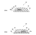
- FIG. 4A is a cross-sectional view schematically showing a configuration of a biosensor according to a second embodiment
- FIG. 4A is a cross-sectional view taken along line AA in FIG. 3
- FIG. 4B is a cross-sectional view taken along line BB in FIG.
- a biosensor 10 shown in FIG. 1 includes a collection unit 12 and a field effect transistor (FET) 14.
- the biosensor 10 detects glucose as a detection target substance contained in the sample solution in the sampling unit 12, and detects the amount of glucose in the sample solution by converting the identified information into an electrical signal in the FET 14.
- examples of the sample liquid include non-invasively collected sample liquid, that is, biological fluid other than blood, such as sweat, tears, and saliva.
- sample solutions contain proteins such as albumin as a non-detection target substance in addition to glucose.
- the collecting unit 12 has two receiving units arranged separately, that is, a first receiving unit 16 and a second receiving unit 18.
- the first receiving portion 16 and the second receiving portion 18 are formed so that the sample liquid can be moved from the distal end to the proximal end, and are separated by the separation portion 20.
- the separation unit 20 can prevent the sample liquid moving from the distal end to the proximal end from being mixed.
- the first receiving unit 16 separates glucose in the sample solution from the protein while moving the sample solution from the distal end to the proximal end.
- the 1st receiving part 16 is formed with the filter paper cut
- the first receiving portion 16 is electrically connected to the FET 14 on the proximal end side.
- the first receiving part 16 includes an identification substance 22.
- the identification substance 22 has a function of binding to glucose contained in the sample solution.
- phenylboronic acid for example, a derivative thereof (for example, phenylboronic acid having a vinyl group), glucose binding protein (GBP), a derivative thereof, or the like can be used as the identification substance 22.
- phenylboronic acid generates a negative charge when bound to glucose.
- the identification substance 22 is supported on a carrier (not shown).
- conductive particles or non-conductive particles can be used.
- the conductive particles metal particles such as particles such as Au, Pt, Ag, and Cu, and non-metal particles such as particles such as indium tin oxide (ITO) and a conductive polymer can be used.
- the non-conductive particles for example, particles such as SiO 2 can be used.
- a thiol group (—SH) or a disulfide group (—S—S—) into phenylboronic acid as the discriminating substance 22 to obtain a derivative of thiol or disulfide phenylboronic acid is attached to the surface of Au particles. It can be supported.
- the first receiving portion 16 may have an elastic portion 24 formed thereon.
- the elastic part 24 is formed on the surface opposite to the surface facing the second receiving part 18.
- the elastic part 24 is not formed on the proximal end side of the first receiving part 16.
- the elastic part 24 can be formed of a biocompatible material, for example, hydrogel.
- a hydrogel is a gel-like material in which hydrophilic polymer chains are cross-linked to retain a large amount of water and has excellent water absorption.
- agarose silicone, polyhydroxyethyl methacrylate (Poly-HEMA, polymethacrylic acid 2 -Also called hydroxyethyl), polyvinylpyrrolidone (PVP), polyvinyl alcohol (PVA), and the like.
- Poly-HEMA may be a homopolymer of hydroxyethyl methacrylate (HEMA) or a copolymer with other monomers (for example, 2,3-dihydroxypropyl methacrylate, glycerol methacrylate (GMA), etc.). Poly-HEMA tends to have a higher water content when it is a copolymer.
- the PVP may be a homopolymer of N-vinyl-2-pyrrolidone (NVP), which is a copolymer obtained by polymerizing NVP as a main component and adding a crosslinking agent with HEMA, methyl methacrylate (MMA) or the like. May be.
- the second receiving portion 18 is not particularly limited, and for example, paper can be used.
- Paper is manufactured by gluing plant fibers and other fibers. Plant fibers are composed of cellulose and hemicellulose. Cellulose has a property in which a large number of hydroxyl groups are bonded to each other by hydrogen bonding, whereby plant fibers constituting the paper adhere to each other. Examples of other fibers include fibers made of minerals, metals, synthetic resins, and the like.
- the second receiving portion 18 is connected to the reference electrode 21 via the salt bridge portion 25 on the proximal end side.
- the salt bridge portion 25 is formed, for example, by hardening a potassium chloride aqueous solution with agar or the like.
- the sample solution that has moved through the second receiving portion 18 and the reference electrode 21 are electrically connected by the salt bridge portion 25 without being in direct contact.
- the second receiving portion 18 may be formed with an elastic portion 24 in the same manner as the first receiving portion 16.
- the elastic portion 24 is formed on the surface opposite to the surface facing the first receiving portion 16.
- the elastic portion 24 is not formed on the base end side of the second receiving portion 18 where the salt bridge portion 25 is provided.
- the FET 14 includes a source electrode part 30 electrically connected to a source (not shown) formed on the surface of the semiconductor substrate 28, a drain electrode part 32 electrically connected to a drain (not shown), a semiconductor A gate insulating film (not shown) formed on the substrate 28, the source electrode portion 30 and the drain electrode portion 32;
- the FET 14 can use either n-MOS or p-MOS.
- a gate electrode 34 is formed on the gate insulating film.
- the gate electrode 34 can be formed of Au, Ag, Cu or the like.
- the source electrode part 30 and the drain electrode part 32 are electrically connected to a power source and a measuring instrument.
- the semiconductor substrate 28 may be formed of Si, Ga, As, ITO, IGZO, IZO, or the like, or an organic semiconductor, a carbon semiconductor (for example, a carbon nanotube, a graphene semiconductor, a diamond semiconductor, or the like) may be used.
- the gate insulating film can be formed by SiO 2, Si 3 N 4 ( SiN x), an oxide or nitride such as Ta 2 O 5, Al 2 O 3.
- the biosensor 10 includes a main body 36 that holds the collection unit 12 and the FET 14.
- the main body 36 is a cubic member formed of a synthetic resin such as polyethylene terephthalate (PET), polytetrafluoroethylene (PTFE), and the first receiving portion setting portion 38 and the second receiving portion setting.
- PET polyethylene terephthalate
- PTFE polytetrafluoroethylene
- Part 40, FET installation part 42, separation part 20, probe insertion hole 44, and reference electrode insertion hole 46 Part 40, FET installation part 42, separation part 20, probe insertion hole 44, and reference electrode insertion hole 46.
- the main body 36 has two holes extending from one end to the other end in the longitudinal direction on the upper and lower sides of one surface in the thickness direction.
- the lower hole is the first receiving portion setting portion 38
- the upper hole is the second receiving portion setting portion 40.
- a separation unit 20 is formed between the first receiving unit installation unit 38 and the second receiving unit installation unit 40.
- An FET installation portion 42 is formed on the other end side of the first receiving portion installation portion 38.
- a probe insertion hole 44 connected to the surface of the other end side in the longitudinal direction of the main body 36 is formed in the FET installation portion 42.
- Two probe insertion holes 44 are provided side by side in the vertical direction with respect to the paper surface of this figure.
- a salt bridge installation part 45 is formed on the other end side of the second receiving part installation part 40.
- a reference electrode insertion hole 46 connected to the surface of the other end side in the longitudinal direction of the main body 36 is formed.
- the FET 14 is installed in the FET installation part 42 in a state where the source electrode part 30 and the drain electrode part 32 are respectively aligned with the probe insertion holes 44.
- the gate electrode 34 is disposed at a connection portion with the first receiving portion installation portion 38.
- the first receiving part 16 is installed in the first receiving part installation part 38 with the elastic part 24 facing downward. Further, the first receiving portion 16 has a distal end protruding from one end of the main body 36, and a base end surface in contact with the gate electrode 34 of the FET 14.
- Probe electrodes 47 are inserted into the probe insertion holes 44, respectively. The tips of the probe electrodes 47 are in contact with the source electrode portion 30 and the drain electrode portion 32, respectively, and are electrically connected to the source and the drain, respectively.
- the salt bridge installation part 45 is filled with the salt bridge part 25.
- the second receiving part 18 is installed in the second receiving part installation part 40 with the elastic part 24 facing upward. Further, the second receiving portion 18 has a distal end protruding from one end of the main body 36, and a proximal end surface in contact with the salt bridge portion 25.
- the reference electrode 21 is inserted into the reference electrode insertion hole 46.
- the reference electrode 21 has a tip inserted into the salt bridge portion 25 and is electrically connected to the salt bridge portion 25.
- the reference electrode 21 becomes a reference potential in the FET 14.
- a sample solution is collected by the collection unit 12.
- the tear fluid as the sample solution is collected by bringing the tip of the collection unit 12 into direct contact with the inside of the lower eyelid.
- the first receiving portion 16 and the second receiving portion 18 are provided with the elastic portion 24 on the distal end side, thereby collecting tears without damaging the eyeball and the surrounding skin. Can do.
- the collected tears penetrate the first receiving part 16 and the second receiving part 18 from the distal end toward the proximal end.
- the 1st receiving part 16 is formed with filter paper, glucose in tears penetrates faster than protein.
- Glucose binds to the identification substance 22 in the first receiving unit 16.
- the identification substance 22 generates a negative charge.
- the tear fluid permeates to the proximal end side and reaches the salt bridge portion 25, whereby the tear fluid is electrically connected to the reference electrode 21 through the salt bridge portion 25.
- the negative charge is charged on the surface of the gate electrode 34 on the base end side of the first receiving portion 16. Thereby, the charge density on the gate electrode 34 changes.
- This change in charge density can be measured as a change in drain current flowing from the source to the drain with reference to the potential of the tear reference electrode 21.
- a change in charge density on the gate electrode 34 is measured as a change in gate voltage.
- the first receiving portion 16 is formed of filter paper, so that glucose in tear fluid penetrates faster than protein and reaches the proximal end side of the first receiving portion 16 faster than protein. .
- the biosensor 10 can suppress the protein from binding to the identification substance 22 included in the first receiving unit 16 or adhering to the surface of the gate electrode 34, so that an unnecessary negative charge is charged in the gate electrode 34. Can be suppressed. Therefore, since the biosensor 10 can further improve the measurement sensitivity, the amount of glucose can be more reliably measured based on the sample liquid collected from the human body non-invasively.
- the biosensor 10 is formed such that the first receiving portion 16 and the second receiving portion 18 are separated by the separating portion 20 on the proximal end side, and the sample liquid that has penetrated from the distal end is not mixed on the proximal end side. Further, a salt bridge portion 25 is provided on the proximal end side of the second receiving portion 18. Thereby, the biosensor 10 uses the reference electrode 21 electrically connected to the tears via the salt bridge portion 25 as a reference, and the charge density on the gate electrode 34 connected to the other end side of the first receiving portion 16. Can be measured.
- the biosensor 10 according to the above embodiment was manufactured, and the output voltage of the FET 14 when the sampling unit 12 was brought into contact with the inner side of the lower arm was measured.
- Paper manufactured by ADVANTEC, product name: qualitative filter paper No. 131
- ADVANTEC product name: qualitative filter paper No. 131
- gold particles particle size: 15 nm
- a solution concentration: 1 nM
- Paper manufactured by ADVANTEC, product name: qualitative filter paper No. 131
- a Pt electrode was used as the reference electrode 21.
- the separation part 20 was a plate-like member having a thickness of 300 ⁇ m formed of PTFE.
- An Au electrode was used as the gate electrode 34 of the FET 14.
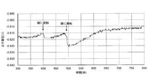
- the sampling part 12 of the biosensor 10 thus produced was brought into contact with a human eyeball for 10 seconds, and the change in the charge density on the gate electrode 34 was measured as the change in the drain-source voltage.
- the result is shown in FIG.
- the vertical axis represents output voltage (V)
- the horizontal axis represents time (seconds). From this figure, it was confirmed that the output voltage changed almost at the same time when the sampling part 12 was brought into contact with the eye. From this, the biosensor 10 measures the change in the charge density on the gate electrode 34 caused by the glucose in the tear fluid collected by the collection unit 12 in the first receiving unit 16 being combined with the identification substance 22. I was able to confirm that it was possible.
- the present invention is not limited to the above-described embodiment, and can be appropriately changed within the scope of the gist of the present invention.
- the present invention is not limited thereto, and is formed of a structure such as a synthetic resin having a flow path or an organic polymer nonwoven fabric. May be.
- the present invention is not limited to this, and a self-assembled monolayer (Self-Assembled) containing the identification substance 22 and an inhibitor is included.
- Monolayers SAMs
- the inhibitory substance prevents proteins such as albumin that are non-detection target substances from binding to phenylboronic acid or reaching the gate electrode 34.
- SAMs generally refer to organic thin films in which organic molecules spontaneously gather at a solid-liquid interface or a solid-gas interface to form a monomolecular film spontaneously.
- the inhibitor is formed of a polymer compound.
- the polymer compound oligoethylene glycol having a molecular chain longer than that of the identification substance 22 can be used, and for example, polyethylene glycol can be used.
- the first receiving unit 16 may use a copolymer bonded to the identification substance 22 and the inhibitory substance.
- the inhibitor can be formed of a hydrophilic polymer.
- the hydrophilic polymer is a polymer having a hydrophilic functional group (hydroxyl group, carboxyl group), such as hydrogel, paper, superabsorbent polymer (SAP).
- Hydrogel is a gel-like material in which hydrophilic polymer chains are cross-linked and retains a large amount of water and is excellent in water absorption, for example, polyhydroxyethyl methacrylate (Poly-HEMA, polyhydroxymethacrylate 2-hydroxyethyl). And polyvinyl pyrrolidone (PVP), polyvinyl alcohol (PVA), and the like.
- Poly-HEMA may be a homopolymer of hydroxyethyl methacrylate (HEMA) or a copolymer with other monomers (for example, 2,3-dihydroxypropyl methacrylate, glycerol methacrylate (GMA), etc.).
- Poly-HEMA tends to have a higher water content when it is a copolymer.
- the PVP may be a homopolymer of N-vinyl-2-pyrrolidone (NVP), which is a copolymer obtained by polymerizing NVP as a main component and adding a crosslinking agent with HEMA, methyl methacrylate (MMA) or the like. May be.
- NVP N-vinyl-2-pyrrolidone
- MMA methyl methacrylate
- Paper is manufactured by gluing plant fibers and other fibers.
- Plant fibers are composed of cellulose and hemicellulose.
- Cellulose has a property in which a large number of hydroxyl groups are bonded to each other by hydrogen bonding, whereby plant fibers constituting the paper adhere to each other.
- other fibers include fibers made of minerals, metals, synthetic resins, and the like. From the viewpoint of fixing the identification substance 22 more firmly, paper made of plant fibers (cellulose) is used. Is preferred.
- SAP is a polymer that can absorb and retain water from several hundred times to several thousand times its own weight.
- a polymer of acrylic acid can be used. Since a polymer of acrylic acid has a large number of carboxyl groups, it has a high hydrophilicity and is further crosslinked to a fine structure to form a gel having a high water absorption when it is in the form of sodium salt.
- hydrophilic polymers examples include cellulose derivatives such as hydroxypropylmethylcellulose (HPMC), sodium carboxymethylcellulose (CMC-Na), and hydroxyethylcellulose (HEC); polysaccharides such as alginic acid, hyaluronic acid, agarose, starch, dextran, and pullulan.
- HPMC hydroxypropylmethylcellulose
- CMC-Na sodium carboxymethylcellulose
- HEC hydroxyethylcellulose
- polysaccharides such as alginic acid, hyaluronic acid, agarose, starch, dextran, and pullulan.
- a homopolymer such as carboxyvinyl polymer, polyethylene oxide, poly (meth) acrylamide, poly (meth) acrylic acid, a copolymer of the homopolymer and polysaccharide, and a monomer constituting the homopolymer; Copolymers with other monomers; proteins such as collagen and gelatin and derivatives thereof; heparin, hyaluronic acid, chondroitin sulfate, dermatan sulfate, dextran sulfate, keratan sulfate, heparan Mention may be made of glycosaminoglycans such as acid, chitin, polysaccharides and mucopolysaccharides such as chitosan.
- 1-vinyl-2-pyrrolidinone, propenoic acid 2-methyl ester, monomethacryloyloxyethyl phthalate, ammonium sulfatoethyl methacrylate, N-vinylpyrrolidone, N, N-dimethylacrylamide, 2- (methacryloyloxyethyl) ) -2- (Trimethylammonioethyl) phosphate and other hydrophilic polymers may be used.
- hydrophilic polymers exemplified above may be used alone or in combination of two or more.
- a known radical polymerization accelerator can be appropriately selected and used.
- those having water solubility or water dispersibility and uniformly contained in the entire system are preferably used.
- water-soluble peroxides such as potassium peroxodisulfate and ammonium peroxodisulfate, water-soluble azo compounds such as VA-044, V-50, and V-501 (all of which are Wako Pure Chemical Industries, Ltd.)
- a mixture of Fe 2+ and hydrogen peroxide can be used.
- N, N'-methylenebisacrylamide, ethylene glycol dimethacrylate, vinyl methacrylate, or the like can be used as the crosslinking agent.
- the first receiving portion 16 has a structure including the identification substance 22 from the distal end side to the proximal end side, but is not limited thereto.
- the identification substance 22 that binds to glucose is included on the proximal end side of the first receiving unit 16, and a substance other than glucose (for example, a protein such as albumin) preferentially adheres to the distal end side of the first receiving unit 16.
- a structure including a substance, specifically, a substance that easily binds to a thiol group, gold particles, or platinum particles may be used. Such a structure is preferable because measurement sensitivity can be increased.
- the separation portion 20 is formed integrally with the main body 36 .
- the present invention is not limited to this, and the separation portion 20 may be formed so as to be separable independently of the main body 36. .
- the present invention is not limited thereto, and the first main body 36 that holds the sampling unit 12 and the FET 14.
- the second main body 36 that holds Thereby, the biosensor can replace only the collection part.
- the detection target substance is glucose
- the present invention is not limited to this.
- the present invention may be applied to sodium ions or potassium ions as the detection target substance.
- crown ether can be used as the identification substance.
- the present invention is not limited to this, and a thin film is directly formed on the salt bridge portion 25 to form the reference electrode. May be.
- the second receiving portion 18 is formed of paper
- the present invention is not limited thereto, and may be formed of hydrogel.
- the second receiving portion 18 does not need to be further provided with the elastic portion 24.
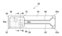
- the biosensor 50 shown in a partial top view in FIG. 3 includes a measurement electrode 60 and a reference electrode 62 that are separately formed on a rectangular substrate 54.
- the measurement electrode 60 and the reference electrode 62 are formed along the long side of the substrate 54, and the base ends 60 b and 62 b of each electrode reach the end of the substrate 54.
- the measurement electrode 60 is provided with a first receiving portion 56 at the tip, and the reference electrode 62 is provided with a second receiving portion 58 at the tip.
- the 1st receiving part 56 and the 2nd receiving part 58 are arrange
- the biosensor 50 identifies glucose as a detection target substance contained in the sample solution in the collection unit 52, and converts the identified information into an electrical signal in an FET (not shown). Thus, the amount of glucose in the sample solution is detected.
- the measurement electrode 60 can be formed by a gold electrode, for example.
- the base end 60b side of the measurement electrode 60 is electrically connected to an FET (not shown).
- the base end 60b side of the measurement electrode 60 is used as the gate electrode of the FET. Since the measurement electrode 60 has the first receiving portion 56 at the tip, the gate electrode of the FET in the biosensor 50 is connected to the first receiving portion 56.
- the first receiving unit 56 and the second receiving unit 58 are arranged separately.
- the first receiving part 56 and the second receiving part 58 arranged separately are covered with a porous elastic layer 70.
- the porous elastic layer 70 can be formed of a biocompatible material, for example, a porous gel obtained by making a hydrogel porous. Examples of the hydrogel include polyhydroxyethyl methacrylate as described in the first embodiment.
- the first receiving part 56 is provided with a MIP (Molecular Template Imprinted Polymer) gel layer 66 on the surface of the tip 60a of the measurement electrode 60.
- the MIP gel layer 66 is a gel layer containing an identification substance, and the gel layer is formed of a hydrogel.
- the identification substance a compound having a function of binding to glucose contained in the sample solution can be used as in the case of the first embodiment.
- the hydrogel include polyhydroxyethyl methacrylate as described in the first embodiment.
- the first receiving unit 56 separates glucose in the sample solution that has permeated the porous elastic layer 70 from the protein in the MIP gel layer 66.
- a blocking layer 64 is provided between the tip 60 a of the measurement electrode 60 and the MIP gel layer 66.
- the blocking layer 64 contains an inhibitor.
- the inhibitor has a protein removing action, and for example, a monolayer of albumin can be used.
- the inhibitory substance suppresses the protein that is the non-detection target substance from reaching the gate electrode.
- the second receiving portion 58 has a configuration in which the conductor portion 62a is covered with a salt bridge portion 68 as shown in FIG. 4B.
- the conductor part 62a and the reference electrode 62 are integrally formed, and the tip of the reference electrode 62 is used as the conductor part 62a.
- the second receiving portion 58 is connected to the reference electrode 62 through the salt bridge portion 68.
- the reference electrode 62 can be formed, for example, by covering a gold electrode with silver / silver chloride. As a gold electrode here, the thing similar to the measurement electrode 60 can be used.
- the salt bridge portion 68 is preferably a gel layer that is less likely to pass water than the porous elastic layer 70.
- the salt bridge portion 68 is formed by hardening a potassium chloride aqueous solution with agar or the like.
- the conductor portion 62a that is the tip of the sample solution and the reference electrode 62 is similar to the salt bridge portion 68 as in the first embodiment.
- electrical connection is made without direct contact.
- the base end 62b of the reference electrode 62 is connected to a measuring instrument.
- the FET (not shown) has basically the same configuration as that of the first embodiment. As described above, in the present embodiment, the base end 60b side of the measurement electrode 60 connected to the first receiving portion 56 is used as the gate electrode of the FET. The reference electrode 62 connected to the second receiving portion 58 becomes a reference potential in the FET.
- a sample solution is collected by the collection unit 52.
- tear fluid as a sample solution is collected.
- the collection unit 52 is provided with the porous elastic layer 70 that covers the first receiving unit 56 and the second receiving unit 58, so that the tears can be obtained without damaging the eyeball and surrounding skin. Can be collected.
- the collected tears penetrate into the porous elastic layer 70 toward the first receiving portion 56 and the second receiving portion 58.
- the porous elastic layer 70 is formed of a porous gel, so that glucose in tear fluid penetrates faster than the protein and reaches the first receiving unit 56.
- glucose binds to the identification substance in the MIP gel layer 66.
- the identification substance generates a negative charge. Proteins that are non-detection target substances are blocked by the blocking layer 64.
- tear fluid is electrically connected to the reference electrode 62 via the salt bridge portion 68.
- the identification substance is included in the MIP gel layer 66. Since the glucose in the tear fluid is taken into the molecular template in the MIP gel layer 66, the effect that glucose can be recognized more reliably is also obtained.
- the blocking layer 64 made of a monolayer of albumin is not a dense structure having a flat surface.
- the monolayer of albumin has a complicated structure on the surface, and there are gaps inside. Proteins that are non-detection target substances are captured in this complicated structure.
- the gel forming the MIP gel layer 66 enters the gap between the monomolecular films, and the MIP gel layer 66 is partially connected to the tip 60 a of the measurement electrode 60. The negative charges generated in the MIP gel layer 66 can reach the tip 60a of the measurement electrode 60 via such a gel.
- the negative charge is charged on the surface of the gate electrode.
- the negative charge is charged from the first receiving portion 56 via the measurement electrode 60 to the surface of the gate electrode on the base end 60 b side of the measurement electrode 60.
- the charge density of the gate electrode changes. This change in charge density can be measured as a change in drain current flowing from the source to the drain with reference to the potential of the tear reference electrode 62.
- the change in charge density on the gate electrode is measured as the change in gate voltage.
- the porous elastic layer 70 is formed of a porous gel, so that glucose in the tear fluid penetrates faster than the protein and reaches the first receiving unit 56.
- the tear fluid permeates the blocking layer 64 containing the inhibitory substance via the MIP gel layer 66 containing the identification substance.
- glucose in tears binds to the identification substance, so that the identification substance generates a negative charge.
- the inhibitory substance in the blocking layer 64 prevents the protein that is the non-detection target substance from reaching the gate electrode.
- the biosensor 50 can suppress the protein from adhering to the surface of the gate electrode, it can suppress the unnecessary negative charge from being charged to the gate electrode. Therefore, since the biosensor 50 can further improve the measurement sensitivity, it is possible to more reliably measure the amount of glucose based on the sample solution collected from the human body non-invasively.
- the first receiving portion 56 and the second receiving portion 58 are arranged separately, and the porous elastic layer 70 made of a porous gel covers the first and second receiving portions 56, 58. Is provided. Due to the presence of the porous elastic layer 70, tears can permeate at a high speed and quickly reach the first receiving portion 56 and the second receiving portion 58.
- the measurement electrode is based on the reference electrode 62 electrically connected to the tear fluid as in the case of the first embodiment.
- the change in charge density on the gate electrode on the other end 60b side of 60 can be measured.
- the biosensor 50 according to the second embodiment was manufactured, and the operation was confirmed by bringing the collection unit 52 into contact with the eyeball.
- Two gold electrodes were separated and formed on a glass substrate 54 by a sputtering method, and one gold electrode was used as a measurement electrode 60.
- the other gold electrode is covered with silver / silver chloride as reference electrode 62.
- the tip 60a of the measurement electrode 60 was immersed in a 5 g / L albumin solution overnight after being subjected to ultraviolet ozone treatment.
- the blocking layer 64 was formed in the front-end
- a MIP gel layer 66 was formed using a monomer solution containing vinylphenylboronic acid (0.01 g) as an identification substance as a raw material.
- a monomer solution containing vinylphenylboronic acid (0.01 g) as an identification substance as a raw material.
- HEMA hydroxyethyl methacrylate
- N-3- (dimethylamino) propylmethacrylamide 0.02 g of N, N′-methylenebisacrylamide
- 6.7 300% by weight of sodium acrylate (pH 7.3) 0.009 g of glucose, and 0.01 g of vinylphenylboronic acid were mixed.
- 100 mM sodium phosphate buffer pH 10.0 was added, adjusted to a total amount of 1 g, and dissolved.
- a silver / silver chloride ink (manufactured by BAS, product name: silver chloride ink for reference electrode) was applied on the gold electrode to be the reference electrode 62 and dried in the air for 24 hours. After drying, the conductor portion 62a, which is the tip of the measuring electrode 62 covered with silver / silver chloride, is covered with an agarose gel containing potassium chloride (concentration: 3.3M) to form a salt bridge portion 68, and the second receptor. Part 58 was obtained. On the board
- the first receiving unit 56 and the second receiving unit 58 were covered with the porous elastic layer 70 using a monomer solution as follows.
- the monomer solution here was prepared in the same manner as the raw material of the MIP gel layer except that vinyl phenylboronic acid as an identification substance was not blended.
- Sodium chloride 0.5g was added to the monomer solution so that it might become more than saturated aqueous solution, and the raw material solution of the porous elastic layer 70 was prepared.
- the surface of the substrate 54 on which the first receiving portion 56 and the second receiving portion 58 are arranged apart from each other protected the region other than the sampling portion 52 with hydrogel, and similarly protected the back surface and side surfaces of the substrate 54.
- the substrate 54 in which only the region of the collecting part 52 was exposed was immersed in the raw material solution of the porous elastic layer 70 and subjected to a polymerization reaction at room temperature in a nitrogen atmosphere for 12 hours to produce a hydrogel on the substrate 54. After completion of the polymerization reaction, the substrate 54 was immersed in ultrapure water for 4 hours to remove residual monomer components and sodium chloride crystals. In this way, the first receiving portion 56 having the blocking layer 64 and the MIP gel layer 66 and the second receiving portion 58 having the salt bridge portion 68 were covered with the porous elastic layer 70 to form the sampling portion 52.
- the biosensor 50 was produced using the other end 60b of the measurement electrode 60 as the gate electrode of the FET.
- the collected part 52 of the obtained biosensor 50 was brought into contact with the human eyeball, and the change in charge density was measured on the gate electrode in the same manner as in the first embodiment.
- the biosensor 50 can measure the change in the charge density on the gate electrode caused by the glucose in the tear fluid collected by the collection unit 52 being combined with the identification substance in the MIP gel layer 66. did it.
- the present invention is not limited to the above-described embodiment, and can be appropriately changed within the scope of the gist of the present invention.
- a separation unit may be disposed on the substrate 54 between the first receiving unit 56 and the second receiving unit 58 in the sampling unit 52.
- the separation part can also be arranged between the measurement electrode 60 and the reference electrode 62. By providing the separation part, it is possible to reliably prevent an unintended substance from reaching the reference electrode 62.
- the separation portion can be formed by a technique such as heat curing using a hydrophobic material such as polydimethylpolysiloxane (PDMS) or epoxy.
- PDMS polydimethylpolysiloxane
- the substrate 54 is formed of glass, but is not limited thereto.
- PDMS polymethyl methacrylate
- the substrate 54 can be used as the substrate 54 as long as it is a biocompatible and flexible material.
- the first receiving portion 56 is formed of a gold electrode, but is not limited thereto, and may be formed of silver, copper, platinum, palladium, mercury, or the like.
- the second receiving portion 58 can be formed by covering the gold electrode with silver / silver chloride, or covering the electrode made of silver or copper with silver / silver chloride, for example.
- the compound (identification substance) that binds to glucose contained in the sample solution and the hydrogel as described in the first embodiment are arbitrarily used. In combination, it can be prepared by blending the target substance (glucose).
- the MIP gel layer 66 can be formed by formulating the raw materials so as to obtain a desired molecular template and adopting a general technique.
- the gel layer containing the identification substance is the MIP gel layer including the molecular template polymer, but is not necessarily limited thereto.
- the first receiving portion 56 may be configured by including an identification substance in a gel layer that does not contain the molecular template polymer and providing the gel layer on the blocking layer 64.
- the blocking layer 64 between the MIP gel layer 66 and the first receiving unit 56 only needs to block proteins that are non-detection target substances.
- the blocking layer 64 can be formed using any inhibitor such as polyethylene glycol as mentioned in the first embodiment.
- the salt bridge portion 68 in the second receiving portion 58 is not limited to an agarose gel. If a layer that is harder than the porous elastic layer 70 and can penetrate the sample liquid is obtained, the salt bridge portion 68 can be formed using, for example, HEMA.
- the conductor portion 62 a in the second receiving portion 58 can function as long as it is electrically connected to the reference electrode 62, and does not necessarily have to be formed integrally with the reference electrode 62.
- a hydrogel such as HEMA
- a monomer solution prepared by blending an appropriate salt according to the type of hydrogel so as to become a saturated aqueous solution or more is used as a raw material of the porous elastic layer 70.
- HEMA sodium chloride may be used as the salt.
- the second embodiment can also be applied to sodium ions and potassium ions as detection target substances.
- crown ether is used as the discriminating substance, and the MIP gel layer 66 can be produced with a prescription according to a desired substance to be detected.
Landscapes
- Life Sciences & Earth Sciences (AREA)
- Health & Medical Sciences (AREA)
- Chemical & Material Sciences (AREA)
- Physics & Mathematics (AREA)
- Molecular Biology (AREA)
- Biochemistry (AREA)
- Pathology (AREA)
- Analytical Chemistry (AREA)
- Chemical Kinetics & Catalysis (AREA)
- General Health & Medical Sciences (AREA)
- General Physics & Mathematics (AREA)
- Immunology (AREA)
- Electrochemistry (AREA)
- Engineering & Computer Science (AREA)
- Microelectronics & Electronic Packaging (AREA)
- Spectroscopy & Molecular Physics (AREA)
- Investigating Or Analysing Biological Materials (AREA)
- Measurement Of The Respiration, Hearing Ability, Form, And Blood Characteristics Of Living Organisms (AREA)
- Investigating Or Analyzing Materials By The Use Of Electric Means (AREA)
Abstract
Description
(全体構成)
図1に示すバイオセンサ10は、採取部12と、電界効果トランジスタ(FET:Field Effect Transistor)14とを備える。バイオセンサ10は、採取部12において試料液中に含まれる検出対象物質としてのグルコースを識別し、識別された情報をFET14において電気的な信号に変換することにより、試料液中のグルコース量を検出する。ここで試料液とは、非侵襲的に採取した試料液、すなわち血液以外の生体液として、汗、涙、唾液を挙げることができる。これら試料液には、グルコースのほか、非検出対象物質としてのアルブミン等のタンパク質が含まれている。
上記のように構成されたバイオセンサ10において、まず、採取部12で試料液を採取する。例えば、採取部12の先端を直接下瞼の内側に接触させることにより、試料液としての涙液を採取する。本実施形態の場合、第1受容部16及び第2受容部18は、先端側に弾性部24が設けられていることにより、眼球やその周囲の皮膚を傷つけずに、涙液を採取することができる。
本発明は上記実施形態に限定されるものではなく、本発明の趣旨の範囲内で適宜変更することが可能である。
(全体構成)
図3に部分上面図を示すバイオセンサ50は、矩形状の基板54上に分離して形成された測定電極60及び参照電極62を備えている。測定電極60と参照電極62とは、基板54の長辺に沿って形成され、各電極の基端60b、62bは、基板54の端部に達している。測定電極60は先端に第1受容部56が設けられ、参照電極62は先端に第2受容部58が設けられている。第1受容部56及び第2受容部58は分離して配置されており、第1,第2受容部56,58は、後述するように採取部52を構成している。第1実施形態の場合と同様、バイオセンサ50は、採取部52において試料液中に含まれる検出対象物質としてのグルコースを識別し、識別された情報を図示しないFETにおいて電気的な信号に変換することにより、試料液中のグルコース量を検出する。
上記のように構成されたバイオセンサ50において、まず、採取部52で試料液を採取する。例えば、多孔質弾性層70の表面を直接下瞼に接触させることにより、試料液としての涙液を採取する。本実施形態の場合、採取部52においては第1受容部56及び第2受容部58を覆う多孔質弾性層70が設けられていることにより、眼球やその周囲の皮膚を傷つけずに、涙液を採取することができる。
本発明は上記実施形態に限定されるものではなく、本発明の趣旨の範囲内で適宜変更することが可能である。
12 採取部
16 第1受容部
18 第2受容部
20 分離部
21 参照電極
22 識別物質
24 弾性部
25 塩橋部
50 バイオセンサ
52 採取部
54 基板
56 第1受容部
58 第2受容部
60 測定電極
62 参照電極
64 ブロッキング層
66 MIPゲル層
68 塩橋部
70 多孔質弾性層
Claims (11)
- 試料液を受容し、分離して配置された第1受容部及び第2受容部
を有し、
前記第1受容部が、検出対象物質と結合する識別物質を含むと共に、前記試料液中の検出対象物質を非検出対象物質と分離し、
前記第2受容部が、塩橋部を介して参照電極に接続される
ことを特徴とする採取部。 - 前記第1受容部及び前記第2受容部との間に分離部が配置され、前記塩橋部は、前記第2受容部の基端側に設けられていることを特徴とする請求項1記載の採取部。
- 前記第1受容部及び前記第2受容部は、毛細管現象により前記試料液が先端から基端へ浸透することを特徴とする請求項2記載の採取部。
- 前記第1受容部及び前記第2受容部は、先端側に弾性部を有することを特徴とする請求項2又は3記載の採取部。
- 前記識別物質が、担体に担持されていることを特徴とする請求項2~4のいずれか1項記載の採取部。
- 前記担体が、前記第1受容部の基端側に固定されていることを特徴とする請求項5記載の採取部。
- 前記第1受容部及び前記第2受容部は、単一の基板上に配置され、
前記第1受容部は、前記基板上に形成された測定電極の先端に順に積層された阻害物質を含むブロッキング層と、前記ブロッキング層上の識別物質を含むゲル層とを備え、
前記第2受容部は、前記基板上に形成された参照電極の先端に設けられた塩橋部を有する
ことを特徴とする請求項1記載の採取部。 - 前記第1受容部及び前記第2受容部は、多孔質弾性層で覆われていることを特徴とする請求項7記載の採取部。
- 前記ゲル層は、分子鋳型ポリマーを含むことを特徴とする請求項7又は8記載の採取部。
- 前記識別物質が、フェニルボロン酸であることを特徴とする請求項1~9のいずれか1項記載の採取部。
- 請求項1~10のいずれか1項記載の採取部と、
前記第1受容部とゲート電極が電気的に接続された電界効果トランジスタと
を備えたことを特徴とするバイオセンサ。
Priority Applications (9)
| Application Number | Priority Date | Filing Date | Title |
|---|---|---|---|
| RU2017101678A RU2670572C2 (ru) | 2014-06-23 | 2015-03-24 | Пробоотборник и биосенсор |
| AU2015282264A AU2015282264A1 (en) | 2014-06-23 | 2015-03-24 | Sampling unit and biosensor |
| EP15812759.7A EP3159686B1 (en) | 2014-06-23 | 2015-03-24 | Sampling unit and biosensor |
| US15/320,024 US10197527B2 (en) | 2014-06-23 | 2015-03-24 | Sampling unit and biosensor |
| BR112016030440-3A BR112016030440A2 (ja) | 2014-06-23 | 2015-03-24 | An extraction part and a biosensor |
| CA2952919A CA2952919A1 (en) | 2014-06-23 | 2015-03-24 | Sampling unit and biosensor |
| CN201580033551.0A CN106662549B (zh) | 2014-06-23 | 2015-03-24 | 采样单元和生物传感器 |
| TW104109687A TW201602572A (zh) | 2014-06-23 | 2015-03-26 | 採取部及生物感測器 |
| JP2015154762A JP6591822B2 (ja) | 2014-08-07 | 2015-08-05 | バイオセンサ |
Applications Claiming Priority (2)
| Application Number | Priority Date | Filing Date | Title |
|---|---|---|---|
| JP2014-127845 | 2014-06-23 | ||
| JP2014127845A JP5599012B1 (ja) | 2014-06-23 | 2014-06-23 | 採取部及びバイオセンサ |
Publications (1)
| Publication Number | Publication Date |
|---|---|
| WO2015198668A1 true WO2015198668A1 (ja) | 2015-12-30 |
Family
ID=51840308
Family Applications (1)
| Application Number | Title | Priority Date | Filing Date |
|---|---|---|---|
| PCT/JP2015/058903 Ceased WO2015198668A1 (ja) | 2014-06-23 | 2015-03-24 | 採取部及びバイオセンサ |
Country Status (10)
| Country | Link |
|---|---|
| US (1) | US10197527B2 (ja) |
| EP (1) | EP3159686B1 (ja) |
| JP (1) | JP5599012B1 (ja) |
| CN (1) | CN106662549B (ja) |
| AU (1) | AU2015282264A1 (ja) |
| BR (1) | BR112016030440A2 (ja) |
| CA (1) | CA2952919A1 (ja) |
| RU (1) | RU2670572C2 (ja) |
| TW (1) | TW201602572A (ja) |
| WO (1) | WO2015198668A1 (ja) |
Cited By (2)
| Publication number | Priority date | Publication date | Assignee | Title |
|---|---|---|---|---|
| WO2017192836A1 (en) * | 2016-05-06 | 2017-11-09 | The Johns Hopkins University | A potentiometric wearable sweat sensor |
| EP3435075A4 (en) * | 2016-03-25 | 2019-10-30 | Provigate Inc. | HIGHLY SENSITIVE BIOSENSOR AND METHOD FOR THE PRODUCTION THEREOF |
Families Citing this family (10)
| Publication number | Priority date | Publication date | Assignee | Title |
|---|---|---|---|---|
| JP5599012B1 (ja) * | 2014-06-23 | 2014-10-01 | 国立大学法人 東京大学 | 採取部及びバイオセンサ |
| WO2016084873A1 (ja) | 2014-11-27 | 2016-06-02 | 富士フイルム株式会社 | 表面修飾無機物、表面修飾無機物の製造方法、および無機物表面を有機物で修飾する方法、ならびに放熱材料、熱伝導材料、および潤滑剤 |
| CN106770515B (zh) * | 2016-11-25 | 2019-08-30 | 合肥工业大学 | 一种基于分子印迹膜的有机电化学晶体管传感器 |
| CN107581832B (zh) * | 2017-09-19 | 2019-12-20 | 东莞理工学院 | 一种具有汗液传感器的智能床垫 |
| CN107802293A (zh) * | 2017-11-10 | 2018-03-16 | 湘潭大学 | 一种人体汗液收集的柔性微流体设备及该设备的汗液收集和检测方法 |
| TWI691720B (zh) | 2019-01-18 | 2020-04-21 | 國立清華大學 | 生物感測器 |
| WO2020236945A1 (en) | 2019-05-21 | 2020-11-26 | Illumina, Inc. | Sensors having an active surface |
| CN114689666B (zh) * | 2020-12-31 | 2024-09-20 | 中国科学院苏州纳米技术与纳米仿生研究所 | 汗液电化学传感器及其制作方法、可穿戴装置 |
| EP4277748A4 (en) | 2021-01-15 | 2024-12-25 | Illumina, Inc. | ACTIVATION OF SENSOR-TOP WIRE BONDING |
| WO2024063638A1 (en) * | 2022-09-23 | 2024-03-28 | Universiti Kebangsaan Malaysia | Device for detecting albumin from saliva |
Citations (4)
| Publication number | Priority date | Publication date | Assignee | Title |
|---|---|---|---|---|
| JPS63148159A (ja) * | 1986-12-11 | 1988-06-21 | Horiba Ltd | イオン濃度等の測定方法 |
| JP2004184155A (ja) * | 2002-12-02 | 2004-07-02 | Matsushita Electric Ind Co Ltd | 唾液糖バイオセンサ及び測定方法 |
| JP5447716B1 (ja) * | 2013-04-30 | 2014-03-19 | 国立大学法人 東京大学 | バイオセンサ及び分子識別部材 |
| JP5599012B1 (ja) * | 2014-06-23 | 2014-10-01 | 国立大学法人 東京大学 | 採取部及びバイオセンサ |
Family Cites Families (17)
| Publication number | Priority date | Publication date | Assignee | Title |
|---|---|---|---|---|
| KR900005223B1 (ko) | 1986-12-11 | 1990-07-21 | 가부시끼가이샤 호리바 세이사꾸쇼 | 이온농도등의 측정방법과 그 측정에 사용하는 계측기의 교정용시이트 및 교정방법 |
| US4933048A (en) * | 1988-02-16 | 1990-06-12 | I-Stat Corporation | Reference electrode, method of making and method of using same |
| DE4338732C2 (de) * | 1993-11-12 | 2003-12-11 | Thomas Dandekar | Biosensor (neuer Bauart) |
| AT404992B (de) | 1997-04-17 | 1999-04-26 | Avl List Gmbh | Sensor zur bestimmung eines enzymsubstrates |
| AU5565299A (en) * | 1998-08-17 | 2000-03-06 | California Institute Of Technology | Devices and methods for analysis of non-ionic solutes |
| RU2161653C2 (ru) * | 1998-08-24 | 2001-01-10 | ФАРМАКОВСКИЙ Дмитрий Александрович | Способ количественного электрохимического анализа биомолекул |
| KR100342165B1 (ko) | 1999-03-25 | 2002-06-27 | 배병우 | 자기 진단기능을 갖는 소형 고체상 기준전극 |
| CN1432130A (zh) * | 2000-03-08 | 2003-07-23 | 糖尿病诊断公司 | 快速响应葡萄糖传感器 |
| WO2001073124A2 (en) | 2000-03-28 | 2001-10-04 | Diabetes Diagnostics, Inc. | Rapid response glucose sensor |
| CN1692278A (zh) * | 2002-12-20 | 2005-11-02 | 松下电器产业株式会社 | 生物传感器 |
| KR100611510B1 (ko) | 2003-07-03 | 2006-08-11 | 주식회사 올메디쿠스 | 혈구를 포함하는 생리적 샘플내의 분석물의 농도를측정하기 위한 전기화학적 바이오센서용 테스트스트립 및시약 |
| WO2008044214A1 (en) * | 2006-10-12 | 2008-04-17 | Koninklijke Philips Electronics N.V. | Fast biosensor with reagent layer |
| JP5467312B2 (ja) * | 2008-06-24 | 2014-04-09 | 独立行政法人物質・材料研究機構 | バイオセンサ、バイオセンサを用いた生体物質の検出方法、及びそのキット |
| US20110082356A1 (en) * | 2009-10-01 | 2011-04-07 | Medtronic Minimed, Inc. | Analyte sensor apparatuses having interference rejection membranes and methods for making and using them |
| JP5398017B2 (ja) * | 2010-07-22 | 2014-01-29 | 国立大学法人 東京大学 | 検出デバイス及びバイオセンサ |
| EP2570803B1 (en) | 2011-09-16 | 2018-03-21 | Nxp B.V. | pH sensor and manufacturing method |
| DE102012216497A1 (de) | 2012-09-17 | 2014-03-20 | Robert Bosch Gmbh | Elektronische Sensorvorrichtung zum Detektieren von chemischen oder biologischen Spezies, mikrofluidische Vorrichtung mit einer derartigen Sensorvorrichtung sowie Verfahren zum Herstellen der Sensorvorrichtung und Verfahren zum Herstellen der mikrofluidischen Vorrichtung |
-
2014
- 2014-06-23 JP JP2014127845A patent/JP5599012B1/ja active Active
-
2015
- 2015-03-24 AU AU2015282264A patent/AU2015282264A1/en not_active Abandoned
- 2015-03-24 BR BR112016030440-3A patent/BR112016030440A2/ja not_active Application Discontinuation
- 2015-03-24 CA CA2952919A patent/CA2952919A1/en not_active Abandoned
- 2015-03-24 EP EP15812759.7A patent/EP3159686B1/en active Active
- 2015-03-24 WO PCT/JP2015/058903 patent/WO2015198668A1/ja not_active Ceased
- 2015-03-24 RU RU2017101678A patent/RU2670572C2/ru not_active IP Right Cessation
- 2015-03-24 US US15/320,024 patent/US10197527B2/en active Active
- 2015-03-24 CN CN201580033551.0A patent/CN106662549B/zh active Active
- 2015-03-26 TW TW104109687A patent/TW201602572A/zh unknown
Patent Citations (4)
| Publication number | Priority date | Publication date | Assignee | Title |
|---|---|---|---|---|
| JPS63148159A (ja) * | 1986-12-11 | 1988-06-21 | Horiba Ltd | イオン濃度等の測定方法 |
| JP2004184155A (ja) * | 2002-12-02 | 2004-07-02 | Matsushita Electric Ind Co Ltd | 唾液糖バイオセンサ及び測定方法 |
| JP5447716B1 (ja) * | 2013-04-30 | 2014-03-19 | 国立大学法人 東京大学 | バイオセンサ及び分子識別部材 |
| JP5599012B1 (ja) * | 2014-06-23 | 2014-10-01 | 国立大学法人 東京大学 | 採取部及びバイオセンサ |
Non-Patent Citations (1)
| Title |
|---|
| See also references of EP3159686A4 * |
Cited By (4)
| Publication number | Priority date | Publication date | Assignee | Title |
|---|---|---|---|---|
| EP3435075A4 (en) * | 2016-03-25 | 2019-10-30 | Provigate Inc. | HIGHLY SENSITIVE BIOSENSOR AND METHOD FOR THE PRODUCTION THEREOF |
| US10996194B2 (en) | 2016-03-25 | 2021-05-04 | Provigate Inc. | High-sensitivity biosensor and method for producing the same |
| WO2017192836A1 (en) * | 2016-05-06 | 2017-11-09 | The Johns Hopkins University | A potentiometric wearable sweat sensor |
| US11272868B2 (en) | 2016-05-06 | 2022-03-15 | The Johns Hopkins University | Potentiometric wearable sweat sensor |
Also Published As
| Publication number | Publication date |
|---|---|
| EP3159686A1 (en) | 2017-04-26 |
| CA2952919A1 (en) | 2015-12-30 |
| RU2670572C2 (ru) | 2018-10-23 |
| EP3159686A4 (en) | 2017-12-27 |
| BR112016030440A2 (ja) | 2018-07-17 |
| RU2017101678A3 (ja) | 2018-09-20 |
| US20170122899A1 (en) | 2017-05-04 |
| JP5599012B1 (ja) | 2014-10-01 |
| TW201602572A (zh) | 2016-01-16 |
| CN106662549A (zh) | 2017-05-10 |
| RU2017101678A (ru) | 2018-07-19 |
| CN106662549B (zh) | 2019-10-22 |
| US10197527B2 (en) | 2019-02-05 |
| JP2016008823A (ja) | 2016-01-18 |
| AU2015282264A1 (en) | 2017-01-12 |
| EP3159686B1 (en) | 2023-04-26 |
Similar Documents
| Publication | Publication Date | Title |
|---|---|---|
| CN106662549B (zh) | 采样单元和生物传感器 | |
| US11630078B2 (en) | Biosensor | |
| US10620155B2 (en) | Biosensor and molecular identification member | |
| JP6591822B2 (ja) | バイオセンサ | |
| WO2005103670A1 (ja) | ラボオンチップ用基板 | |
| EP4519690A1 (en) | Engineered particles as red blood cell mimics and compositions containing same for hematology | |
| US20220192601A1 (en) | Flexible device, method for producing flexible device | |
| EP3098604A1 (en) | Gel for sensor and sensor | |
| JP4854638B2 (ja) | 安定型ヘモグロビンA1c値の測定方法 | |
| JPWO2019188902A1 (ja) | バイオセンサ | |
| JP2021152477A (ja) | バイオセンサ及び複合センサ | |
| WO2018025876A1 (ja) | 測定装置及び測定方法 | |
| TW201606303A (zh) | 生物感測器 | |
| WO2020117170A1 (en) | Glucose biosensor based on polyphosphonoundecyl acrylate-co-polyvinylimidazole-co-polyvinylferrocene-co-polyglycidyl methacrylate tetra block copolymer | |
| JP4524395B2 (ja) | チオール基又はスルフィド基含有化合物の検出、濃度測定方法 | |
| CN116987285A (zh) | 一种导电水凝胶及其制备方法和应用 |
Legal Events
| Date | Code | Title | Description |
|---|---|---|---|
| 121 | Ep: the epo has been informed by wipo that ep was designated in this application |
Ref document number: 15812759 Country of ref document: EP Kind code of ref document: A1 |
|
| REEP | Request for entry into the european phase |
Ref document number: 2015812759 Country of ref document: EP |
|
| WWE | Wipo information: entry into national phase |
Ref document number: 2015812759 Country of ref document: EP |
|
| ENP | Entry into the national phase |
Ref document number: 2952919 Country of ref document: CA |
|
| WWE | Wipo information: entry into national phase |
Ref document number: 15320024 Country of ref document: US |
|
| NENP | Non-entry into the national phase |
Ref country code: DE |
|
| ENP | Entry into the national phase |
Ref document number: 2015282264 Country of ref document: AU Date of ref document: 20150324 Kind code of ref document: A |
|
| ENP | Entry into the national phase |
Ref document number: 2017101678 Country of ref document: RU Kind code of ref document: A |
|
| REG | Reference to national code |
Ref country code: BR Ref legal event code: B01A Ref document number: 112016030440 Country of ref document: BR |
|
| ENP | Entry into the national phase |
Ref document number: 112016030440 Country of ref document: BR Kind code of ref document: A2 Effective date: 20161223 |