WO2015198740A1 - 工作機械及び加工方法 - Google Patents
工作機械及び加工方法 Download PDFInfo
- Publication number
- WO2015198740A1 WO2015198740A1 PCT/JP2015/064002 JP2015064002W WO2015198740A1 WO 2015198740 A1 WO2015198740 A1 WO 2015198740A1 JP 2015064002 W JP2015064002 W JP 2015064002W WO 2015198740 A1 WO2015198740 A1 WO 2015198740A1
- Authority
- WO
- WIPO (PCT)
- Prior art keywords
- workpiece
- cutting
- tool
- rotating member
- cutting edge
- Prior art date
- Legal status (The legal status is an assumption and is not a legal conclusion. Google has not performed a legal analysis and makes no representation as to the accuracy of the status listed.)
- Ceased
Links
Images

Classifications
-
- B—PERFORMING OPERATIONS; TRANSPORTING
- B23—MACHINE TOOLS; METAL-WORKING NOT OTHERWISE PROVIDED FOR
- B23B—TURNING; BORING
- B23B29/00—Holders for non-rotary cutting tools; Boring bars or boring heads; Accessories for tool holders
- B23B29/24—Tool holders for a plurality of cutting tools, e.g. turrets
- B23B29/32—Turrets adjustable by power drive, i.e. turret heads
- B23B29/323—Turrets with power operated angular positioning devices
-
- B—PERFORMING OPERATIONS; TRANSPORTING
- B23—MACHINE TOOLS; METAL-WORKING NOT OTHERWISE PROVIDED FOR
- B23B—TURNING; BORING
- B23B1/00—Methods for turning or working essentially requiring the use of turning-machines; Use of auxiliary equipment in connection with such methods
-
- B—PERFORMING OPERATIONS; TRANSPORTING
- B23—MACHINE TOOLS; METAL-WORKING NOT OTHERWISE PROVIDED FOR
- B23B—TURNING; BORING
- B23B27/00—Tools for turning or boring machines; Tools of a similar kind in general; Accessories therefor
- B23B27/14—Cutting tools of which the bits or tips or cutting inserts are of special material
- B23B27/16—Cutting tools of which the bits or tips or cutting inserts are of special material with exchangeable cutting bits or cutting inserts, e.g. able to be clamped
- B23B27/1685—Adjustable position of the cutting inserts
- B23B27/1692—Angular position of the cutting insert adjustable around an axis parallel to the chip-forming plane
-
- B—PERFORMING OPERATIONS; TRANSPORTING
- B23—MACHINE TOOLS; METAL-WORKING NOT OTHERWISE PROVIDED FOR
- B23B—TURNING; BORING
- B23B29/00—Holders for non-rotary cutting tools; Boring bars or boring heads; Accessories for tool holders
- B23B29/04—Tool holders for a single cutting tool
- B23B29/12—Special arrangements on tool holders
-
- B—PERFORMING OPERATIONS; TRANSPORTING
- B23—MACHINE TOOLS; METAL-WORKING NOT OTHERWISE PROVIDED FOR
- B23B—TURNING; BORING
- B23B29/00—Holders for non-rotary cutting tools; Boring bars or boring heads; Accessories for tool holders
- B23B29/04—Tool holders for a single cutting tool
-
- B—PERFORMING OPERATIONS; TRANSPORTING
- B23—MACHINE TOOLS; METAL-WORKING NOT OTHERWISE PROVIDED FOR
- B23B—TURNING; BORING
- B23B3/00—General-purpose turning-machines or devices, e.g. centre lathes with feed rod and lead screw; Sets of turning-machines
- B23B3/06—Turning-machines or devices characterised only by the special arrangement of constructional units
Definitions
- the present invention relates to a machine tool and a machining method for cutting a workpiece.
- a lathe which is one of machine tools, holds a workpiece to be processed on a rotating shaft (spindle) and performs cutting with a cutting tool such as a cutting tool while rotating the workpiece.
- a processing method using such a lathe for example, a processing method is known in which a workpiece is cut while feeding a cutting tool in a tangential direction of the workpiece (direction intersecting the rotation axis) (see Patent Document 1).
- the cutting edge of the cutting tool is arranged in a state inclined at a predetermined angle with respect to the generatrix direction of the cutting portion of the workpiece.
- the load on the workpiece increases, and the workpiece may chatter or bend. For this reason, it is necessary to adjust the direction of the blade edge (blade edge angle) to reduce the load applied to the workpiece.
- a plurality of types of cutting tools and holders having different cutting edge angles with respect to the work bus bar have been prepared, and the cutting tools or holders have been replaced when changing the cutting edge direction.
- the method of exchanging the cutting tool and the holder involves a troublesome work such as removal and attachment of the cutting tool and the like, and the work takes time.
- an object of the present invention is to provide a machine tool and a machining method capable of easily and quickly changing the direction of the cutting edge of a cutting tool.
- a machine tool includes a cutting tool having a spindle that holds and rotates a workpiece and a linear cutting blade that cuts the workpiece.
- the cutting direction is a Z direction parallel to the axis of the spindle, a direction perpendicular to the Z direction, and a cutting amount with respect to the workpiece.
- a moving device that moves relative to the workpiece in a moving direction that includes at least a Y direction orthogonal to any of the X direction and the Z direction when the direction of the straight cutting edge is viewed from the X direction.
- a holder that holds the cutting tool in a state tilted by a predetermined angle, and an angle adjustment mechanism that changes the predetermined angle are provided.
- the moving direction may be a direction in which the Z direction and the Y direction are combined.
- the angle adjusting mechanism may include a rotating member that can rotate around an axis parallel to the X direction, and the holder may be attached to the rotating member. Further, the rotating member may be formed integrally with the holder. Moreover, you may provide the drive part which rotates a rotation member. In addition, the rotation member and the support unit that supports the rotation member may be provided with an indicator unit that indicates a predetermined angle. Moreover, you may provide the control part which controls the movement of a moving apparatus based on the information regarding a predetermined angle and a workpiece
- the machining method of the present invention is a method of machining a workpiece that is held and rotated by a main shaft, and includes a cutting tool having a linear cutting edge for cutting the workpiece in a Z direction parallel to the axis of the main shaft and a Z direction. And moving relative to the workpiece in a moving direction including at least the Y direction orthogonal to both the X direction and the X direction defining the cutting amount for the workpiece, and the direction of the linear cutting edge from the X direction It includes holding the cutting tool in a state inclined by a predetermined angle with respect to the Z direction, and changing the predetermined angle.
- the predetermined angle is changed by the angle adjustment mechanism in a state where the cutting tool is held by the holder so that the direction of the linear cutting edge when viewed from the X direction is inclined by a predetermined angle with respect to the Z direction. Therefore, the predetermined angle can be adjusted without exchanging the cutting tool or the holder. Thereby, the direction of the cutting edge of the cutting tool can be changed easily and in a short time.
- the moving direction is a direction that combines the Z direction and the Y direction
- a wide range can be cut in the Z direction relative to the workpiece, reducing the processing time. it can.
- the angle adjusting mechanism has a rotating member that can rotate around an axis parallel to the X direction and the holder is attached to the rotating member, the cutting tool is rotated together with the holder by rotating the rotating member. be able to. Thereby, the predetermined angle can be easily adjusted. Further, when the rotating member is formed integrally with the holder, the length to the blade edge (overhang) can be reduced.
- the predetermined angle can be automatically adjusted by driving the driving unit.
- the rotating member and the support portion that supports the rotating member are provided with an index portion indicating a predetermined angle
- the rotation of the rotating member can be adjusted using the index, and therefore the predetermined angle can be easily adjusted.
- an apparatus that includes a control unit that controls movement of the moving device based on information about a predetermined angle and a workpiece can perform optimum machining that increases machining accuracy without reducing machining efficiency.
- the predetermined angle can be changed in a state where the cutting tool is held such that the direction of the straight cutting edge when viewed from the X direction is inclined by a predetermined angle with respect to the Z direction. Therefore, the direction of the cutting edge of the cutting tool can be changed easily and in a short time according to the workpiece machining conditions, and the workpiece can be machined with high accuracy.
- (A) is a view when the inside of the tool post is viewed in the + Z direction
- (b) is a cross-sectional view taken along line AA of (a).
- An example of the tool head which concerns on a modification is shown, (a) is a perspective view, (b) is the figure seen from Q direction of (a). It is the figure which expanded and showed the part corresponding to the workpiece
- movement of a cutting tool is shown, (a) is the figure seen from X direction, (b) is the figure which looked at the example from which a blade edge
- the X axis is a direction that is orthogonal to the Z direction and that defines a cutting amount for the workpiece.
- the direction of the arrow in the figure is the + direction
- the direction opposite to the arrow direction is the ⁇ direction.
- a machining method including holding the cutting tool in a state tilted by a predetermined angle with respect to the Z direction and changing the predetermined angle is performed.
- FIG. 1 shows an example of a main part of a machine tool 100 according to the first embodiment, where (a) is a side view and (b) is a front view.
- a machine tool 100 shown in FIG. 1 is a lathe.
- the + Y side of the machine tool 100 is the front surface
- the ⁇ Y side is the back surface.
- the ⁇ Z side of the machine tool 100 is a side surface
- the Z direction is the left-right direction of the machine tool 100.
- the machine tool 100 has a base 1.
- the base 1 is provided with a headstock 2 and a tailstock 4.
- the headstock 2 supports the spindle 7 in a rotatable state by a bearing (not shown) or the like.
- the headstock 2 is fixed to the base 1 but may be formed so as to be movable in the Z direction, the X direction, the Y direction, and the like, and may be moved by driving a motor or the like.
- a chuck driving unit 9 is provided at the end of the main shaft 7 on the + Z side. The chuck drive unit 9 holds the workpiece W by moving the plurality of grasping claws 9 a in the radial direction of the main shaft 7. In FIG.
- the workpiece W is gripped using three gripping claws 9 a arranged at equal intervals around the rotation axis of the main shaft 7.
- the present invention is not limited to this, and the number and shape of the gripping claws 9 a are An arbitrary configuration capable of holding W is used.
- claw 9a is formed in the shape (for example, column shape etc.) which has the cylindrical surface Wa.
- the end of the spindle 7 on the ⁇ Z side protrudes from the headstock 2 in the ⁇ Z direction, and a pulley 11 is attached to this end.
- a belt 13 is stretched between the pulley 11 and the rotating shaft of the motor 12 provided on the base 1.
- the rotational speed of the motor 12 is controlled by an instruction from a control unit (not shown).
- a control unit not shown.
- a motor having a torque control mechanism is used as the motor 12.
- the main shaft 7 is not limited to being driven by the motor 12 and the belt 13, and may be one that transmits the drive of the motor 12 to the main shaft 7 by a gear train or the like, or one that rotates the main shaft 7 directly by the motor 12. .
- the tailstock 4 is formed to be movable along the Z-direction guide 3 installed on the base 1.
- the tailstock 4 supports the opposed shaft 8 in a rotatable state by a bearing (not shown) or the like.
- the direction of the rotation axis of the main shaft 7 and the direction of the rotation axis of the opposed shaft 8 are aligned with the Z direction.
- a center 10 is attached to the end of the tailstock 4 on the ⁇ Z side.
- the opposed shaft 8 may be fixed to the tailstock 4 and used as a dead center.
- the base 1 is provided with a Z direction guide 5 arranged in the Z direction. Further, at the ⁇ X position of the Z direction guide 5, similarly to the Z direction guide 5, a Z direction guide 5 A arranged in the Z direction is provided.
- Each of the Z-direction guides 5 and 5A is provided with Z-axis slides 17 and 17A that can move in the Z-direction along the Z-direction guides 5 and 5A.
- the Z-axis slide 17 is moved in the Z direction by driving of a Z-direction drive system (moving device) M1, and is held at a predetermined position. For example, an electric motor or hydraulic pressure is used for the Z-direction drive system M1.
- the Z-axis slide 17A has a drive system similar to the Z-direction drive system M1 described above, and is moved in the Z direction and held at a predetermined position by the drive of the drive system.
- the drive system for the Z-axis slide 17A may have the same configuration as the Z-direction drive system M1, or may have a different configuration.
- X-direction guides 18 and 18A are formed on the Z-axis slides 17 and 17A, respectively.
- the Z-axis slides 17 and 17A are provided with X-axis slides 15 and 15A that can move along the X-direction guides 18 and 18A, respectively.
- the X-axis slide 15 moves in the X direction by being driven by an X-direction drive system (moving device) M2, and is held at a predetermined position.
- an electric motor or hydraulic pressure is used for the X-direction drive system M2.
- the X-axis slide 15A has a drive system similar to the X-direction drive system M2 described above, and is moved in the X direction and held at a predetermined position by the drive of the drive system.
- the drive system for the X-axis slide 15A may have the same configuration as the X-direction drive system M2, or may have a different configuration.
- the Y-direction guides 16 and 16A are formed on the X-axis slides 15 and 15A, respectively.
- the X-axis slides 15 and 15A are provided with tool post driving units 21 and 21A that can move along the Y-direction guides 16 and 16A, respectively.
- the tool post driving unit 21 is moved in the Y direction by driving of a Y direction driving system (moving device) M3 and is held at a predetermined position.
- a Y direction driving system moving device
- an electric motor or hydraulic pressure is used for the Y-direction drive system M3.
- the tool post driving unit 21A has a drive system similar to the Y-direction drive system M3 described above, and is moved in the Y direction by the drive of the drive system and held at a predetermined position.
- the drive system of the tool post drive unit 21A may have the same configuration as the Y-direction drive system M3, or may have a different configuration.
- the Z-direction drive system M1, the X-direction drive system M2, and the Y-direction drive system M3 are controlled by the control unit CONT.
- Each of the tool post driving units 21 and 21A accommodates a rotary driving device such as a motor.
- a first turret 23 is attached to the tool post driving unit 21.
- the first turret 23 is rotatable about the Z direction as driven by a rotary drive device.
- a second turret 23A is attached to the tool post driving unit 21A.
- the second turret 23A is rotatable about the Z direction as driven by a rotary drive device.
- the first turret 23 is disposed above the workpiece W (+ X side), and the second turret 23A is disposed below the workpiece W ( ⁇ X side).
- a plurality of holding portions for holding the cutting tool T are provided on the peripheral surfaces of the first and second turrets 23 and 23A.
- the cutting tool T is held on all or part of these holding portions. Therefore, the desired cutting tool T is selected by rotating the first and second turrets 23 and 23A.
- the cutting tool T held by the holding portions of the first and second turrets 23 and 23A can be exchanged for each holding portion.
- a rotating tool such as a drill or an end mill may be used in addition to a cutting tool for cutting the workpiece W.
- the first and second turrets 23 and 23A are formed with tool heads 24 and 24A as one of a plurality of holding portions.
- the tool heads 24 and 24A may have the same configuration or different configurations.
- the second turret 23A may not be provided with the tool head 24A.
- the cutting tool T1 is attached to the tool head 24 via a holder 25 (see FIG. 2).
- a cutting tool T is attached to the tool head 24A via a holder (not shown).
- the cutting tool T may be the same as or different from the cutting tool T1 attached to the tool head 24.
- the cutting tools T and T1 are arranged on the ⁇ X side with respect to the workpiece W so as to sandwich the workpiece W, but either one may be used. Moreover, although the cutting tools T and T1 are arrange
- work W may be made into the X direction. Moreover, the cutting to the workpiece
- the first and second turrets 23 and 23A are used as the tool post, but the present invention is not limited to this, and a comb-like tool post may be used.
- the comb-like tool post holds the cutting tool T in each of the plurality of comb teeth portions, and selects any one of the plurality of cutting tools T by moving in the direction in which the comb teeth are arranged.
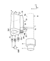
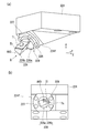
- FIG. 2 is an enlarged perspective view showing a main part including the main shaft 7 and the first turret 23 as a part corresponding to the workpiece W.
- the tool head 24 is detachably attached to the ⁇ X side surface 23 a of the first turret 23.
- a holder 25 is attached to the ⁇ X side of the tool head 24 via a rotating member 26 described later.
- the holder 25 holds the cutting tool T1.
- the cutting tool T1 is set so that the straight cutting edge Th is along the YZ plane.
- Cutting tool T1 prescribes
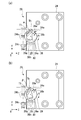
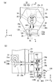
- FIGS. 3A and 3B are diagrams showing the configuration of the tool head 24 on the ⁇ X side. As shown in FIGS. 3A and 3B, a cylindrical opening 24 a is formed on the ⁇ X side of the tool head 24. A rotating member 26 described later is inserted into the opening 24 a of the tool head 24.
- a protruding portion 24 b is provided on the ⁇ Z side end surface of the tool head 24.
- the protrusion 24b protrudes in the ⁇ Z direction, and a notch 24d is formed.
- the cut portion 24d is formed linearly from the tip of the protruding portion 24b toward the -Z direction.
- the cut portion 24d cuts the protrusion 24b to the opening 24a and the + Z side of the opening 24a, and the protrusion 24b is divided into two.
- the tool head 24 is formed to be elastically deformable so that the opening 24a is narrowed when a force is applied in a direction in which the divided protrusions 24b are brought closer to each other (for example, the Y direction). .
- the divided protrusions 24b are fastened by bolts 24c.
- a force is applied so that the divided protrusions 24b approach each other in the Y direction. Accordingly, the inner wall portion of the opening 24 a is fixed so as to tighten the rotating member 26. Further, by loosening the bolt 24c, the force acting between the divided protrusions 24b is released, and the tightening to the rotating member 26 is eased. In this case, the rotation member 26 is in a state of being rotatable around the axis of the rotation axis AX parallel to the X direction.
- Such a rotating member 26 is formed in a columnar shape, for example, and is supported by the tool head 24 while being inserted into the opening 24a.
- the tool head 24 is provided as a support portion that supports the rotating member 26.
- the rotating member 26 is formed with a guide 26g for mounting the holder 25.
- the guide 26g is formed in a linear shape, for example.
- a holder contact surface 26h is provided at an end portion in the longitudinal direction of the guide 26g (the end portion on the -Y side in FIG. 3A).
- the holder 25 is positioned by contacting the holder 25 with the holder contact surface 26h.
- the holder contact surface 26h is a surface that receives the cutting force of the cutting tool T.
- the dimension (width) of the guide 26 g in the short direction is set according to the dimension of the holder 25.
- the holder 25 is fixed to the rotating member 26 by a fixing member (not shown). By fixing the holder 25 to the guide 26g, the direction of the straight cutting edge Th of the cutting tool T1 is fixed to the rotating member 26 in one direction. By rotating the rotating member 26 around the rotation axis AX in this state, the holder 25 and the cutting tool T1 rotate integrally with the rotating member 26, and the direction of the linear cutting blade Th is changed.
- the indicator portions 26 a and 26 b are formed on the ⁇ X side end surface of the rotating member 26.
- the indicator portions 26 a and 26 b are formed in an isosceles triangle shape, and for example, the apex is directed to the outer periphery of the rotating member 26.
- An index portion 24e is formed on the ⁇ X side surface of the tool head 24.
- the indicator portion 24e is formed in an isosceles triangle shape, and for example, the apex is directed to the rotating member 26 side.
- the vertex of the indicator portion 26a or the indicator portion 26b is arranged corresponding to the vertex of the indicator portion 24e on the tool head 24 side.
- the indicator portions 26a and 26b may be a scale or the like.
- the indicator portion 26a is configured so that the linear cutting blade Th is inclined by an angle ⁇ (eg, 45 °) with respect to the Z direction when viewed in the X direction in a state where the holder 25 is mounted on the rotating member 26.
- the rotational position is shown.
- an angle (predetermined angle) at which the linear cutting blade Th is inclined with respect to the Z direction when viewed in the X direction is referred to as a “blade edge angle”.
- FIG. 3A shows a state in which the index part 26a and the index part 24e correspond to each other.
- the blade edge angle can be set to ⁇ by adjusting the rotational position of the rotating member 26 so that the vertex of the indicator portion 26a corresponds to the vertex of the indicator portion 24e.
- the indicator portion 26b indicates the rotational position of the rotating member 26 such that the blade edge angle is ⁇ (eg, 60 °).
- FIG. 3B shows a state in which the index part 26b and the index part 24e correspond to each other.
- the blade edge angle can be set to ⁇ by adjusting the rotational position of the rotating member 26 so that the vertex of the indicator portion 26b corresponds to the vertex of the indicator portion 24e.
- the indicator part corresponding to the blade edge angle different from (alpha) and (beta) may be provided separately.
- the operator rotates the rotating member 26 about the rotation axis AX so that the index portions 26a, 26b and the index portion 24e correspond to each other with the bolt 24c loosened, whereby the blade edge angle is set to a preset angle. (Eg, angle ⁇ , angle ⁇ , etc.). Thereby, it is possible to efficiently change the direction of the straight cutting edge Th to a preset direction.
- the rotating member 26 and the tool head 24 that supports the rotating member 26 are provided as an angle adjusting mechanism 29 capable of changing the blade edge angle.
- the operation of the machine tool 100 configured as described above will be described.
- the workpiece W to be processed is held on the spindle 7.
- the workpiece 12 is rotated by driving the motor 12 and rotating the spindle 7.
- work W is suitably set according to a process.
- the first turret 23 is rotated to select the cutting tool T1.
- the rotating member 26 Prior to selecting the cutting tool T1, the rotating member 26 is inserted into the opening 24a provided in the tool head 24 of the first turret 23. Then, the cutting tool T1 is mounted on the holder 25, and the holder 25 is mounted on the rotating member 26 (guide 26g) of the tool head 24.
- the holder 25 is fixed to the rotating member 26 with a bolt or the like (not shown).
- the straight cutting edge Th is disposed in a direction parallel to the YZ plane, and is tilted by a predetermined angle with respect to the Z direction as viewed from the X direction. Thereafter, the blade edge angle is changed by rotating the rotating member 26. At this time, the operator can easily set the blade edge angle by associating the indicator portions 26 a and 26 b provided on the rotating member 26 with the indicator portion 24 e provided on the tool head 24.
- the position of the cutting tool T1 in the X direction is adjusted.
- the tool post driving unit 21 is moved in the X direction by the X direction driving system M2 so that the straight cutting edge Th of the cutting tool T1 corresponds to the cylindrical surface Wa of the workpiece W.
- the position in the X direction of the straight cutting edge Th defines the cutting amount of the workpiece W with respect to the cylindrical surface Wa.
- the cutting amount may be set to a value set in advance by the control unit CONT, or may be performed by an operator's manual operation.
- the XYZ coordinate position at which the linear cutting edge Th of the cutting tool T1 moves is set by, for example, movement of the Z-axis slide 17 in the Z direction and movement of the tool head 24 in the Y direction.
- This setting is performed by driving the Z-direction drive system M1 and the Y-direction drive system M3, respectively, based on the control of the control unit CONT.
- the straight cutting edge Th of the cutting tool T1 is moved in the Y direction that is the tangential direction of the cylindrical surface Wa of the workpiece W to perform the processing.
- Such movement of the cutting tool T1 in the Y direction is performed based on, for example, machining information (machining recipe) preset in a storage unit or the like provided in a control unit (not shown).
- machining information machining recipe
- the operator may manually operate the movement of the cutting tool T1.
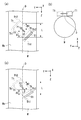
- FIG. 4A shows the operation of the cutting tool T1 (straight cutting edge Th) when the workpiece W is viewed in the ⁇ X direction when the cutting edge angle is ⁇ (eg, 45 °).
- FIG. 4B shows the operation of the cutting tool T1 (straight cutting blade Th) viewed from the Z direction.
- FIG. 4C shows the operation of the cutting tool T1 (straight cutting blade Th) when the workpiece W is viewed in the ⁇ X direction when the blade edge angle is ⁇ (eg, 60 °).
- the straight cutting edge Th of the cutting tool T1 is ⁇ with respect to the generatrix (axis) D in the Z direction on the cylindrical surface Wa of the workpiece W.
- the + Z side of the straight cutting edge Th comes into contact with the workpiece W first.
- the moving direction is a trajectory along a tangent plane with respect to the cylindrical surface Wa of the workpiece W.
- the first end Th1 on the + Z side of the straight cutting edge Th hits the cylindrical surface Wa, and the cylindrical surface Wa is cut at the first end Th1.
- the linear cutting edge Th moves in the + Y direction and the ⁇ Z direction (directions P1, P2) along the cylindrical surface Wa, so that the cutting portion of the workpiece W is changed from the first end portion Th1 to the second end portion Th2.
- the state gradually shifts in the -Z direction toward.
- the linear cutting edge Th moves in the directions P1 and P2
- the cutting portion of the cylindrical surface Wa of the workpiece W advances in the Z direction.
- the cutting of the cylindrical surface Wa is completed when the second end Th2 of the straight cutting edge Th is away from the bus D. As described above, the entire cylindrical surface Wa is cut from the first end Th1 to the second end Th2 of the straight cutting edge Th. However, the cylindrical surface Wa is cut using a part of the straight cutting edge Th. May be.
- the length L of the generatrix D is cut by moving the straight cutting edge Th in the direction P1.
- the length L is the length A1 (cos ⁇ of the width of the straight cutting edge Th) projected from the straight cutting edge Th on the bus D, and the Z direction during which the straight cutting edge Th moves in the direction P1 and cuts the bus D Is added to the length B1.
- the length L is similarly cut by moving the straight cutting edge Th in the direction P2.
- the length L is the length A2 (cos ⁇ of the length of Th) projected from the straight cutting edge Th on the bus D, and the length in the Z direction while the straight cutting edge Th moves in the direction P2 and cuts the bus D And B2.
- the cutting edge as in the first case. If the angle is small, the load on the workpiece W (cutting force on the workpiece) becomes large, and chatter vibration or deflection is likely to occur on the workpiece W. On the other hand, in the second case, since the blade edge angle is larger than that in the first case, the load on the workpiece W is reduced when the same feed amount as that in the first case is set. W chatter vibration and deflection are less likely to occur.
- the blade edge angle is set small. (For example, set as ⁇ ).
- the cutting range of the straight cutting edge Th in the Z direction is increased, the processing time can be shortened, and the surface accuracy can be improved.
- the cutting edge angle is set to a large value without changing the feed amount (for example, ⁇ is set). ) As a result, the cutting range in the Z direction of the straight cutting edge Th is reduced, so that the load on the workpiece W is reduced, and the workpiece W is less prone to chatter vibration and deflection.
- the workpiece W may be cut by adding the cutting tool T (see FIG. 1) of the second turret 23A.
- the cylindrical surface Wa may be cut by moving the cutting tool T of the second turret 23A on the ⁇ X side of the workpiece W along the same orbit as the cutting tool T1 described above.
- the cylindrical surface Wa is cut by both the cutting tools T1 and T, the same circumferential portion of the cylindrical surface Wa may be cut with different cutting amounts, and different portions of the cylindrical surface Wa may be cut respectively.
- the holding by the grasping claw 9a is released, and the workpiece W is taken out.
- the cutting tool T1 is held by the holder 25 so that the direction of the straight cutting edge Th when viewed from the X direction is inclined by a predetermined angle with respect to the Z direction.
- the blade edge angle can be changed by the angle adjusting mechanism 29, the blade edge angle can be adjusted without replacing the cutting tool T1 or the holder 25. Thereby, it becomes possible to change the direction of the cutting edge of the cutting tool T1 easily and in a short time.
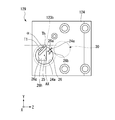
- FIG. 5 shows an example when the tool head 124 is viewed in the + X direction in the machine tool 200 according to the second embodiment.
- 5 is the same as the machine tool 100 shown in FIG.
- the same or equivalent components as those in the first embodiment are denoted by the same reference numerals, and the description thereof is omitted or simplified.
- the configuration of the angle adjustment mechanism 129 is different from the angle adjustment mechanism of the first embodiment (a configuration in which the rotating member 26 is rotated by an operator).
- the angle adjustment mechanism 129 includes a tool head 124, a rotating member 26, and a drive unit 30.
- the drive unit 30 rotates the rotating member 26.
- the drive unit 30 is controlled by, for example, the control unit CONT.
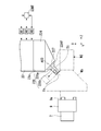
- FIG. 6 is a view of the inside of the first turret 23 (second turret 23A) when viewed in the + Z direction, and (b) is a cross-sectional view taken along the line AA of (a).
- the drive unit 30 includes a motor 31, a worm gear 32, a transmission shaft 33, and bevel gears 34 and 35.
- the motor 31 is disposed on the + Z side of the first turret 23 and is attached to the tool post driving unit 21, for example.
- the motor 31 has an output shaft 31a parallel to the Y direction.
- the output shaft 31a rotates around a rotation axis parallel to the Y direction.
- the worm gear 32 has a screw gear 32 a attached to the output shaft 31 a and a helical gear 32 b attached to the transmission shaft 33.
- the worm gear 32 transmits the rotation of the output shaft 31 a to the transmission shaft 33.
- the transmission shaft 33 is rotatably supported by, for example, bearings 33a and 33b around a rotation axis parallel to the Z direction.
- a helical gear 32b is attached to the end of the transmission shaft 33 on the + Z side.
- a bevel gear 34 is attached to the end of the transmission shaft 33 on the ⁇ Z side.
- the bevel gear 34 is engaged with the bevel gear 35.
- the bevel gear 35 is attached to the shaft 122.
- the bevel gears 34 and 35 transmit the rotation of the transmission shaft 33 to the shaft 122.
- the shaft 122 has a rotation axis AX2 parallel to the X direction, and rotates around the axis of the rotation axis AX2 by the driving force from the driving unit 30.
- the shaft 122 is rotatably supported by bearings 36a and 36b, for example.
- the gear 123 a is formed at the ⁇ X side end of the shaft 122 and rotates around the X axis integrally with the shaft 122.
- the gear 123b is formed on the outer peripheral surface of the rotating member 26.
- the rotation axis of the gear 123b coincides with the rotation axis AX1 of the rotation member 26.
- a plurality of teeth parallel to the X direction are arranged along the cylindrical surface of the rotating member 26 in the gear 123b.
- the gear 123b is meshed with the gear 123a, and rotates around the axis of the rotation axis AX1 by the rotation of the gear 123a.
- the gear 123a rotates and a rotational force is applied to the gear 123b. With this force, the rotation member 26 rotates around the axis of the rotation axis AX1.
- the rotating member 26 has a shaft portion 26 a supported by a slide bearing 125.
- the inner peripheral surface of the slide bearing 125 receives and supports the radial force (radial force) of the shaft portion 26a, and the lower end ( ⁇ X side end surface) of the slide bearing 125 is the thrust force (force in the X direction) of the rotating member 26. ) Receive and support.
- the edge angle of the straight cutting edge Th of the cutting tool T1 attached to the holder 25 is changed. Further, while the drive unit 30 stops driving, the changed blade edge angle is maintained.
- the rotational position of the rotary member 26 is set according to the drive of the drive unit 30, and thereby the edge angle of the straight cutting edge Th of the cutting tool T1 attached to the holder 25 is set.
- the blade edge angle can be automatically adjusted by driving the drive unit 30. Therefore, the edge angle can be adjusted without replacing the cutting tool T1 or the holder 25. Thereby, the direction of the straight cutting edge Th of the cutting tool T1 can be changed easily and in a short time.
- the drive unit 30 can be automatically controlled by the control of the control unit CONT, for example, when the diameter, rigidity, and gripping rigidity of the workpiece W change in the Z direction, these changes are made.
- the blade edge angle (the direction of the straight cutting blade Th) can be automatically changed according to. For example, in the vicinity of the grasping claw 9a, the cutting edge angle can be set to a low angle, the feed rate can be increased, and machining can be performed in a short time.
- the blade edge angle is set to a high angle, the feed rate is set to a low speed, and the cylindricity and surface roughness are suppressed while suppressing chatter vibration and bending of the workpiece W It can be processed so that the degree does not decrease. Thereby, high quality processing can be performed efficiently.
- the cutting edge angle may be changed in synchronization with the feed of the cutting tool T1 in the Y direction or the rotation of the main shaft 7.
- work W may be provided, and the structure which changes a blade edge angle according to the detection result of a sensor may be sufficient.
- the rotation member 26 is provided separately from the holder 25, and the configuration in which the holder 25 is attached to the rotation member 26 has been described as an example.
- the present invention is not limited to this.
- the rotating member 26 may be integrated.
- FIGS. 7A and 7B show an example of a tool head 224 according to a modified example, where FIG. 7A is a perspective view and FIG. 7B is a view seen from the Q direction of FIG. FIG. 8 is a view when the first turret 23 is viewed in the ⁇ Y direction.
- the tool head 224 has a tool placement surface 224f on which the cutting tool T1 is placed.
- the tool placement surface 224f is formed to be inclined with respect to the surface 23a (YZ plane) of the first turret 23 and is directed toward the main shaft 7 (see FIG. 8).
- the cutting tool T1 is held by the tool head 224 via the rotating member 226.
- the rotating member 226 has a rotating part 226a and a holder part 226b.
- the rotating part 226a and the holder part 226b are integrally formed.
- the rotating part 226a is formed in a cylindrical shape and is inserted into an opening (not shown) formed in the tool placement surface 224f.
- the rotating unit 226a is provided to be rotatable around the axis of the rotation axis AX3.
- the opening is formed in a cylindrical shape and has a larger diameter than the rotating part 226a.
- the rotating part 226a is attached via a lock sleeve 227.
- the lock sleeve 227 has a bolt 228 and a press-fit portion (not shown). This press-fitting part is press-fitted between the rotating part 226a and an opening (not shown). The press-fitting portion restricts the rotation of the rotating portion 226a. By fastening the bolt 228, the rotation position of the rotating portion 226a is held by the lock sleeve 227.
- the rotating member 226 can rotate around the axis of the rotation axis AX3.
- the holder part 226b holds the cutting tool T1.
- the direction of the straight cutting edge Th when viewed from the Q direction is inclined. Therefore, the direction of the straight cutting edge Th when viewed from the X direction is also inclined by a predetermined angle with respect to the Z direction.
- the inclination angle (blade edge angle) of the linear cutting blade Th is changed by rotating the rotary member 226 around the axis of the rotation axis AX3 in a state where the press-fitting of the lock sleeve 227 is loosened.
- the angle adjusting mechanism 229 is formed by the rotating member 226, the lock sleeve 227, and the bolt 228.
- the tool head 224 moves in the Z direction and the X direction integrally with the first turret 23 by the Z direction drive system M1 and the X direction drive system M2. Further, the tool head 224 is moved in the Y direction by the Y-direction drive system M3 described above. Therefore, the tool head 224 is provided so as to be movable in the Z direction, the X direction, and the Y direction with respect to the workpiece W by the Z direction drive system M1, the X direction drive system M2, and the Y direction drive system M3. As a result, the cutting tool T1 is movable in a direction in which all or part of the Z direction, the X direction, and the Y direction are combined with the workpiece W.
- the inclined surface Wb of the workpiece W2 is cut by moving the linear cutting blade Th in the direction (movement direction) obtained by combining the X direction, the Y direction, and the Z direction while rotating the workpiece W2.
- the Z-direction drive system M1, the X-direction drive system M2, and the Y-direction drive system M3 are controlled by the control unit CONT.
- the angle adjusting mechanism 229 makes the inclination angle of the linear cutting blade Th with respect to the Z direction when viewed from the X direction (the cutting edge). Angle) can be easily changed. Thereby, the direction of the straight cutting edge Th of the cutting tool T1 can be changed easily and in a short time.
- the configuration shown in FIGS. 7 and 8 the configuration in which the rotating unit 226a is provided integrally with the holder unit 226b has been described as an example. However, the configuration is not limited thereto, and the rotating unit 226a and the holder unit 226b are not limited thereto. And may be formed separately. Further, the configuration in which the holder 25 and the rotating member 26 are integrally provided is not limited to the configuration illustrated in FIGS. 7 and 8 and may be applied to the configuration of each of the above embodiments.
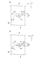
- FIGS. 9A and 9B show an example of moving the cutting tool T1 in the Y direction, where FIG. 9A is a diagram seen from the X direction, and FIG. 9B is a diagram seen from the X direction when the blade edge angles are different.
- FIG. 9A the cutting edge angle ⁇ is set
- FIG. 9B the cutting edge angle ⁇ is set.
- the straight cutting edge Th of the cutting tool T1 moves from the ⁇ Y side to the + Y side with respect to the generatrix D along the tangential plane of the cylindrical surface Wa of the workpiece W.
- the cutting edge angle is smaller than that in FIG. 9B, and the length A1 of the straight cutting edge Th in FIG. It is larger than the length A2 projected onto D.
- Fig.9 (a) it can cut widely in a Z direction by the movement of one Y direction compared with (b).
- the cutting force applied to the workpiece W is larger than that in (b), it causes chatter vibration of the workpiece W and the like. In such a case, the cutting force applied to the workpiece W is reduced by increasing the blade edge angle as shown in FIG.
- the control unit CONT is based on information about required surface roughness, cutting edge angle, workpiece W diameter, and longitudinal dimension (Z direction) of the workpiece W.
- a machining program may be created by automatically calculating the cutting start position and the cutting completion position of T1.
- the control unit CONT controls the Z direction drive system M1, the X direction drive system M2, the Y direction drive system M3, and the like based on the newly created machining program.
- the above information can be input to the machine tool 100 by an operator via an operation panel or the like.
- a sensor for detecting the direction of the straight cutting edge Th may be provided, and the edge angle of the straight cutting edge Th may be controlled by the output from this sensor.
- an optical or magnetic non-contact type sensor may be used.
- the rotating member 26 is not limited to being rotated by the above configuration.
- the rotating member 26 may be directly rotated by a servo motor or the like.
- the angle adjusting mechanism 29 or the like moves the holder 25 relative to the tool head 24 or the like to change the cutting edge angle of the cutting tool T1, but the present invention is not limited to this.
- the angle adjustment mechanism changes the cutting edge angle of the cutting tool T1 by moving the tool head 24 or the first turret 23 or the like, or changes the cutting edge angle by moving the cutting tool T1 relative to the holder 25. But you can.
- the cutting tool T1 is moved with respect to the workpiece W (the main shaft 7 or the like) at the time of cutting.
- the workpiece W is moved with respect to the cutting tool T1.
- the cutting may be performed by moving both the cutting tool T1 and the workpiece W.
Landscapes
- Engineering & Computer Science (AREA)
- Mechanical Engineering (AREA)
- Turning (AREA)
- Cutting Tools, Boring Holders, And Turrets (AREA)
- Milling Processes (AREA)
Abstract
Description
第1実施形態に係る工作機械100について、図面を用いて説明する。図1は、第1実施形態に係る工作機械100の要部の一例を示し、(a)は側面図、(b)は正面図である。図1に示す工作機械100は、旋盤である。図1において、工作機械100の+Y側が正面であり、-Y側が背面である。また、工作機械100の±Z側は側面であり、Z方向は工作機械100の左右方向である。
図3(a)及び(b)に示すように、ツールヘッド24の-X側には、円筒状の開口部24aが形成されている。ツールヘッド24の開口部24aには、後述の回転部材26が挿入される。
第2実施形態に係る工作機械200について説明する。
図5は、第2実施形態に係る工作機械200のうちツールヘッド124を+X方向に見た場合の一例を示している。図5において図示しない構成は、図1に示す工作機械100と同様のものが採用される。また、図5において、第1実施形態と同一または同等の構成部分については同一符号を付けて説明を省略または簡略化する。なお、この第2実施形態は、角度調整機構129の構成が第1実施形態の角度調整機構(回転部材26を作業者が回転させる構成)とは異なっている。図5に示すように、角度調整機構129は、ツールヘッド124と、回転部材26と、駆動部30とを有している。駆動部30は、回転部材26を回転させる。駆動部30は、例えば制御部CONTによって制御される。
例えば、上記各実施形態では、回転部材26がホルダ25と別体で設けられ、ホルダ25を回転部材26に装着する構成を例に挙げて説明したが、これに限定するものではなく、ホルダ25と回転部材26とが一体で設けられた構成であってもよい。
Claims (8)
- ワークを保持して回転する主軸と、
前記ワークを切削する直線切刃を有する切削工具を、前記主軸の軸線に平行なZ方向と、前記Z方向に直交しかつ前記ワークに対する切削量を規定するX方向とのいずれにも直交するY方向を少なくとも含む移動方向に、前記ワークに対して相対的に移動させる移動装置と、
前記直線切刃の方向を前記X方向から見て前記Z方向に対して所定角度傾けた状態で前記切削工具を保持するホルダと、
前記所定角度を変更する角度調整機構と、を備える工作機械。 - 前記移動方向は、前記Z方向と前記Y方向とを合成した方向である請求項1記載の工作機械。
- 前記角度調整機構は、前記X方向に平行な軸線周りに回転可能な回転部材を有し、
前記ホルダは、前記回転部材に取り付けられる請求項1または請求項2記載の工作機械。 - 前記回転部材は、前記ホルダと一体で形成される請求項3記載の工作機械。
- 前記回転部材を回転させる駆動部を備える請求項3または請求項4記載の工作機械。
- 前記回転部材、及び前記回転部材を支持する支持部に、前記所定角度を示す指標部を備える請求項3~請求項5のいずれか1項に記載の工作機械。
- 前記所定角度及び前記ワークに関する情報に基づいて前記移動装置の移動を制御する制御部を備える請求項1~請求項6のいずれか1項に記載の工作機械。
- 主軸に保持されて回転するワークを加工する方法であって、
前記ワークを切削する直線切刃を有する切削工具を、前記主軸の軸線に平行なZ方向と、前記Z方向に直交しかつ前記ワークに対する切削量を規定するX方向とのいずれにも直交するY方向を少なくとも含む移動方向に、前記ワークに対して相対的に移動させることと、
前記直線切刃の方向を前記X方向から見て前記Z方向に対して所定角度傾けた状態で前記切削工具を保持することと、
前記所定角度を変更することと、を含む加工方法。
Priority Applications (3)
| Application Number | Priority Date | Filing Date | Title |
|---|---|---|---|
| EP15811868.7A EP3162478B1 (en) | 2014-06-27 | 2015-05-15 | Machine tool and machining method |
| US15/321,808 US10016815B2 (en) | 2014-06-27 | 2015-05-15 | Machine tool and machining method |
| JP2016529177A JP6217856B2 (ja) | 2014-06-27 | 2015-05-15 | 工作機械及び加工方法 |
Applications Claiming Priority (2)
| Application Number | Priority Date | Filing Date | Title |
|---|---|---|---|
| JP2014132471 | 2014-06-27 | ||
| JP2014-132471 | 2014-06-27 |
Publications (1)
| Publication Number | Publication Date |
|---|---|
| WO2015198740A1 true WO2015198740A1 (ja) | 2015-12-30 |
Family
ID=54937838
Family Applications (1)
| Application Number | Title | Priority Date | Filing Date |
|---|---|---|---|
| PCT/JP2015/064002 Ceased WO2015198740A1 (ja) | 2014-06-27 | 2015-05-15 | 工作機械及び加工方法 |
Country Status (4)
| Country | Link |
|---|---|
| US (1) | US10016815B2 (ja) |
| EP (1) | EP3162478B1 (ja) |
| JP (1) | JP6217856B2 (ja) |
| WO (1) | WO2015198740A1 (ja) |
Cited By (5)
| Publication number | Priority date | Publication date | Assignee | Title |
|---|---|---|---|---|
| JP2018043328A (ja) * | 2016-09-16 | 2018-03-22 | 株式会社ジェイテクト | 切削工具、及び加工方法 |
| EP3330026A1 (de) * | 2016-12-05 | 2018-06-06 | Audi Ag | Drehwerkzeug, insbesondere drehräumwerkzeug |
| JP2021065976A (ja) * | 2019-10-24 | 2021-04-30 | アイシン機工株式会社 | 工具ホルダ |
| CN113681031A (zh) * | 2021-08-30 | 2021-11-23 | 宁夏共享精密加工有限公司 | 一种用于异形槽的加工方法及加工刀具 |
| JP2023138674A (ja) * | 2021-03-31 | 2023-10-02 | 株式会社プロテリアル | 加工方法および工具 |
Families Citing this family (4)
| Publication number | Priority date | Publication date | Assignee | Title |
|---|---|---|---|---|
| KR20170129163A (ko) * | 2015-02-24 | 2017-11-24 | 반두리트 게엠베하 하르트메탈 운트 디아만트베르크초이그 | 회전 피가공재를 기계가공하기 위한 디바이스, 방법 및 절단 플레이트 |
| DE112016001390B4 (de) * | 2015-03-25 | 2023-06-07 | Aisin Kiko Co., Ltd. | Schneidwerkzeug, Schälvorrichtung und Verfahren |
| JP6546950B2 (ja) * | 2017-03-15 | 2019-07-17 | シチズン時計株式会社 | タレット刃物台 |
| JP6775237B2 (ja) * | 2018-08-09 | 2020-10-28 | 国立大学法人東海国立大学機構 | 加工装置および切削加工方法 |
Citations (5)
| Publication number | Priority date | Publication date | Assignee | Title |
|---|---|---|---|---|
| JP2003127008A (ja) * | 2001-10-22 | 2003-05-08 | Minebea Co Ltd | バイトホルダおよびバイトシャンクの保持方法 |
| JP2005501749A (ja) * | 2001-09-11 | 2005-01-20 | べーリンガー ヴェルクツオィクマシーネン ゲーエムベーハー | ねじれを生じない回転対称面の鋼切削方法 |
| JP3984052B2 (ja) * | 1999-12-17 | 2007-09-26 | 住友電工ハードメタル株式会社 | 回転対称面のねじれの発生しない切削加工方法 |
| JP2013244582A (ja) * | 2012-05-29 | 2013-12-09 | Murata Machinery Ltd | Y軸送り台及び旋削機械 |
| JP2014531331A (ja) * | 2011-09-18 | 2014-11-27 | エムアーゲー イーアーエス ゲーエムベーハー | 工作物を仕上げるための方法及び装置 |
Family Cites Families (12)
| Publication number | Priority date | Publication date | Assignee | Title |
|---|---|---|---|---|
| US2803053A (en) * | 1953-06-01 | 1957-08-20 | Fazi Fulvio De | Adjustable toolholder |
| US3484919A (en) * | 1967-10-20 | 1969-12-23 | Carmet Co | Reversible cutting inserts and tool holder for the same |
| JPS60217005A (ja) * | 1984-04-12 | 1985-10-30 | Toshiba Corp | 切削工具 |
| JPH06206145A (ja) | 1991-06-21 | 1994-07-26 | Konica Corp | 切削加工装置 |
| JP2686000B2 (ja) * | 1991-07-17 | 1997-12-08 | 株式会社東芝 | 振動切削方法及び切削装置 |
| EP0792707A1 (en) * | 1996-02-21 | 1997-09-03 | Matsushita Electric Industrial Co., Ltd. | Chip-breaking turning method and apparatus |
| JP2002154007A (ja) * | 2000-09-05 | 2002-05-28 | Yamazaki Mazak Corp | 複合工具 |
| SE526480C2 (sv) * | 2002-10-31 | 2005-09-20 | Sandvik Intellectual Property | Verktyg för spånavskiljande bearbetning |
| US7089838B2 (en) * | 2004-01-28 | 2006-08-15 | Kennametal Inc. | Zero centerline toolholder assembly |
| US20080253847A1 (en) | 2004-08-19 | 2008-10-16 | Manchester Tool Company | Adjustable Machine Tool Cutting Insert Holder Apparatus |
| US7739931B2 (en) * | 2006-07-31 | 2010-06-22 | Xerox Corporation | Tool bit with multiple cutting tips |
| WO2015079836A1 (ja) * | 2013-11-29 | 2015-06-04 | 村田機械株式会社 | 工作機械及び切削方法 |
-
2015
- 2015-05-15 WO PCT/JP2015/064002 patent/WO2015198740A1/ja not_active Ceased
- 2015-05-15 EP EP15811868.7A patent/EP3162478B1/en active Active
- 2015-05-15 US US15/321,808 patent/US10016815B2/en active Active
- 2015-05-15 JP JP2016529177A patent/JP6217856B2/ja active Active
Patent Citations (5)
| Publication number | Priority date | Publication date | Assignee | Title |
|---|---|---|---|---|
| JP3984052B2 (ja) * | 1999-12-17 | 2007-09-26 | 住友電工ハードメタル株式会社 | 回転対称面のねじれの発生しない切削加工方法 |
| JP2005501749A (ja) * | 2001-09-11 | 2005-01-20 | べーリンガー ヴェルクツオィクマシーネン ゲーエムベーハー | ねじれを生じない回転対称面の鋼切削方法 |
| JP2003127008A (ja) * | 2001-10-22 | 2003-05-08 | Minebea Co Ltd | バイトホルダおよびバイトシャンクの保持方法 |
| JP2014531331A (ja) * | 2011-09-18 | 2014-11-27 | エムアーゲー イーアーエス ゲーエムベーハー | 工作物を仕上げるための方法及び装置 |
| JP2013244582A (ja) * | 2012-05-29 | 2013-12-09 | Murata Machinery Ltd | Y軸送り台及び旋削機械 |
Non-Patent Citations (1)
| Title |
|---|
| See also references of EP3162478A4 * |
Cited By (7)
| Publication number | Priority date | Publication date | Assignee | Title |
|---|---|---|---|---|
| JP2018043328A (ja) * | 2016-09-16 | 2018-03-22 | 株式会社ジェイテクト | 切削工具、及び加工方法 |
| EP3330026A1 (de) * | 2016-12-05 | 2018-06-06 | Audi Ag | Drehwerkzeug, insbesondere drehräumwerkzeug |
| JP2021065976A (ja) * | 2019-10-24 | 2021-04-30 | アイシン機工株式会社 | 工具ホルダ |
| JP7345352B2 (ja) | 2019-10-24 | 2023-09-15 | アイシン機工株式会社 | 工具ホルダ |
| JP2023138674A (ja) * | 2021-03-31 | 2023-10-02 | 株式会社プロテリアル | 加工方法および工具 |
| JP7661999B2 (ja) | 2021-03-31 | 2025-04-15 | 株式会社プロテリアル | 加工方法 |
| CN113681031A (zh) * | 2021-08-30 | 2021-11-23 | 宁夏共享精密加工有限公司 | 一种用于异形槽的加工方法及加工刀具 |
Also Published As
| Publication number | Publication date |
|---|---|
| US20170129018A1 (en) | 2017-05-11 |
| EP3162478B1 (en) | 2023-03-29 |
| JPWO2015198740A1 (ja) | 2017-04-20 |
| US10016815B2 (en) | 2018-07-10 |
| JP6217856B2 (ja) | 2017-10-25 |
| EP3162478A1 (en) | 2017-05-03 |
| EP3162478A4 (en) | 2018-02-28 |
Similar Documents
| Publication | Publication Date | Title |
|---|---|---|
| JP6217856B2 (ja) | 工作機械及び加工方法 | |
| JP6206504B2 (ja) | 工作機械及び切削方法 | |
| JP5094465B2 (ja) | 工作機械及び該工作機械を用いたワークの内表面加工方法 | |
| EP3199271B1 (en) | Machine tool and control device for machine tool | |
| US20160368060A1 (en) | Machine tool | |
| JP6638736B2 (ja) | 工作機械及び切削方法 | |
| TWI768194B (zh) | 工作機械 | |
| JP6530633B2 (ja) | 切削方法 | |
| WO2016013307A1 (ja) | 工作機械、工具ユニット、及び加工方法 | |
| JP6604438B2 (ja) | 切削工具支持装置及び工作機械 | |
| WO2019123699A1 (ja) | 工具保持装置及び工作機械 | |
| JP7056138B2 (ja) | 工作機械 | |
| JP4572133B2 (ja) | 中空ワークの内面加工装置 | |
| JP2009066725A (ja) | 複合旋盤及び複合旋盤におけるワークの加工方法 | |
| JP6551521B2 (ja) | 工作機械及び切削方法 | |
| JP2020082278A (ja) | 工作機械及び切削方法 | |
| JP4621569B2 (ja) | 旋盤における主軸交叉内周の加工方法 | |
| JP7441678B2 (ja) | 回転工具装置および工作機械 | |
| JP2013006224A (ja) | 工作機械 | |
| JP7058103B2 (ja) | ワークの端面切削加工方法 | |
| KR20260008017A (ko) | 공작 기계, 및 그 제어 위치 결정 방법 |
Legal Events
| Date | Code | Title | Description |
|---|---|---|---|
| 121 | Ep: the epo has been informed by wipo that ep was designated in this application |
Ref document number: 15811868 Country of ref document: EP Kind code of ref document: A1 |
|
| ENP | Entry into the national phase |
Ref document number: 2016529177 Country of ref document: JP Kind code of ref document: A |
|
| REEP | Request for entry into the european phase |
Ref document number: 2015811868 Country of ref document: EP |
|
| WWE | Wipo information: entry into national phase |
Ref document number: 15321808 Country of ref document: US Ref document number: 2015811868 Country of ref document: EP |
|
| NENP | Non-entry into the national phase |
Ref country code: DE |