WO2015198894A1 - 情報処理装置、情報処理方法、プログラム及び記録媒体 - Google Patents
情報処理装置、情報処理方法、プログラム及び記録媒体 Download PDFInfo
- Publication number
- WO2015198894A1 WO2015198894A1 PCT/JP2015/067051 JP2015067051W WO2015198894A1 WO 2015198894 A1 WO2015198894 A1 WO 2015198894A1 JP 2015067051 W JP2015067051 W JP 2015067051W WO 2015198894 A1 WO2015198894 A1 WO 2015198894A1
- Authority
- WO
- WIPO (PCT)
- Prior art keywords
- transfer function
- connection point
- point
- input
- response
- Prior art date
- Legal status (The legal status is an assumption and is not a legal conclusion. Google has not performed a legal analysis and makes no representation as to the accuracy of the status listed.)
- Ceased
Links
Images




Classifications
-
- G—PHYSICS
- G05—CONTROLLING; REGULATING
- G05B—CONTROL OR REGULATING SYSTEMS IN GENERAL; FUNCTIONAL ELEMENTS OF SUCH SYSTEMS; MONITORING OR TESTING ARRANGEMENTS FOR SUCH SYSTEMS OR ELEMENTS
- G05B19/00—Program-control systems
- G05B19/02—Program-control systems electric
- G05B19/18—Numerical control [NC], i.e. automatically operating machines, in particular machine tools, e.g. in a manufacturing environment, so as to execute positioning, movement or co-ordinated operations by means of program data in numerical form
- G05B19/406—Numerical control [NC], i.e. automatically operating machines, in particular machine tools, e.g. in a manufacturing environment, so as to execute positioning, movement or co-ordinated operations by means of program data in numerical form characterised by monitoring or safety
-
- G—PHYSICS
- G01—MEASURING; TESTING
- G01H—MEASUREMENT OF MECHANICAL VIBRATIONS OR ULTRASONIC, SONIC OR INFRASONIC WAVES
- G01H17/00—Measuring mechanical vibrations or ultrasonic, sonic or infrasonic waves, not provided for in the other groups of this subclass
-
- G—PHYSICS
- G01—MEASURING; TESTING
- G01M—TESTING STATIC OR DYNAMIC BALANCE OF MACHINES OR STRUCTURES; TESTING OF STRUCTURES OR APPARATUS, NOT OTHERWISE PROVIDED FOR
- G01M99/00—Subject matter not provided for in other groups of this subclass
-
- G—PHYSICS
- G06—COMPUTING OR CALCULATING; COUNTING
- G06F—ELECTRIC DIGITAL DATA PROCESSING
- G06F17/00—Digital computing or data processing equipment or methods, specially adapted for specific functions
- G06F17/10—Complex mathematical operations
- G06F17/17—Function evaluation by approximation methods, e.g. inter- or extrapolation, smoothing, least mean square method
-
- G—PHYSICS
- G06—COMPUTING OR CALCULATING; COUNTING
- G06F—ELECTRIC DIGITAL DATA PROCESSING
- G06F30/00—Computer-aided design [CAD]
- G06F30/10—Geometric CAD
- G06F30/15—Vehicle, aircraft or watercraft design
-
- G—PHYSICS
- G06—COMPUTING OR CALCULATING; COUNTING
- G06F—ELECTRIC DIGITAL DATA PROCESSING
- G06F30/00—Computer-aided design [CAD]
- G06F30/20—Design optimisation, verification or simulation
-
- G—PHYSICS
- G05—CONTROLLING; REGULATING
- G05B—CONTROL OR REGULATING SYSTEMS IN GENERAL; FUNCTIONAL ELEMENTS OF SUCH SYSTEMS; MONITORING OR TESTING ARRANGEMENTS FOR SUCH SYSTEMS OR ELEMENTS
- G05B2219/00—Program-control systems
- G05B2219/30—Nc systems
- G05B2219/31—From computer integrated manufacturing till monitoring
- G05B2219/31343—Design of factory, manufacturing system control
-
- G—PHYSICS
- G06—COMPUTING OR CALCULATING; COUNTING
- G06F—ELECTRIC DIGITAL DATA PROCESSING
- G06F2119/00—Details relating to the type or aim of the analysis or the optimisation
- G06F2119/10—Noise analysis or noise optimisation
Definitions
- the present invention relates to an information processing apparatus, an information processing method, a program, and a recording medium.
- a product to be analyzed is defined by dividing it into partial structures, and a contribution analysis is performed at a connection point that transfers force between the partial structures.
- Conventional analysis methods are mainly divided into two methods: a method of estimating the force applied to the connection point by separating the partial structure and a method of estimating the contribution of the transmission path from actual vibration without separation to the partial structure. Classification (for example, see Non-Patent Document 1).
- Problem 1 It takes enormous man-hours to separate the partial structure.
- Problem 2 It takes enormous man-hours to measure the drive point function (transfer function where the input point and the response point are at the same position) at each connection point of the separated partial structure and the transfer function between the connection points.
- the predetermined aspect of the present invention provides an information processing apparatus, an information processing method, a program, and a recording medium that can reduce the man-hours for separating the partial structure and the measurement function of the transfer function and estimate an appropriate transfer function.
- the purpose is to do.
- the information processing apparatus when performing a transmission path analysis of an object, is connected to the object via the input side structure and the input side structure through one or more connection points.
- a response-side structure including an evaluation point is defined, a first self-transfer function obtained by measuring a response at the evaluation point with respect to an input from the evaluation point, and a response between each connection point with respect to the input is measured.
- a vector based on a transfer function between the connection point and the evaluation point using the input unit that inputs each first transfer function obtained in the above, the first self-transfer function, and the first transfer function A first estimator for estimating each second self-transfer function at each connection point in space, and the first estimator for a self-transfer function defined as an inner product of an input-side element vector and an output-side element vector
- a construction unit that constructs a third transfer function at each connection point of the response side structure on the vector space using each second self-transfer function and each second transfer function.
- the information processing method provides an input-side structure connected to the object via the input-side structure and one or more connection points when performing a transmission path analysis of the object.
- a response side structure including an evaluation point is defined, a first self-transfer function obtained by measuring a response at the evaluation point with respect to an input from the evaluation point, and a response at each connection point with respect to the input
- the predetermined aspect of the present invention it is possible to reduce the man-hours for separation into the partial structure and the man-hours for measuring the transfer function and to estimate an appropriate transfer function.
- FIG. 1 It is a figure which shows the actual vehicle experiment data for demonstrating the comparison of the sound pressure when components are replaced
- FIG. 1 is a block diagram illustrating an example of a schematic configuration of an information processing apparatus 10 according to the first embodiment.
- the information processing apparatus 10 includes a central processing unit (CPU) 102, a random access memory (RAM) 104, a read only memory (ROM) 106, a drive device 108, a network I / F ( Interface) 110, an input device 112, and a display device 114. These components are connected to each other via a bus so as to be able to transmit and receive data.
- the CPU 102 is a control unit that controls each device, calculates data, and processes in the computer.
- the CPU 102 is an arithmetic device that executes a program for performing transmission path analysis processing stored in the RAM 104 or the ROM 106.
- the CPU 102 receives input data from the input device 112, the network I / F 110, and the like, calculates and processes the data, and outputs the calculation result to the display device 114, the storage device, and the like.
- the RAM 104 is, for example, a main storage unit.
- the RAM 104 is a storage device that stores or temporarily stores programs and data such as OS (Operating System) and application software that are basic software executed by the CPU 102.
- OS Operating System
- application software that are basic software executed by the CPU 102.
- the ROM 106 is a storage device that stores data related to application software, for example.
- the drive device 108 reads a program and data from a recording medium 116, such as a CD-ROM or an SD card, and installs or downloads the program or data in a storage device.
- a recording medium 116 such as a CD-ROM or an SD card
- a predetermined program is stored in the recording medium 116, and the program stored in the recording medium 116 is installed in the information processing apparatus 10 via the drive device 108.
- the installed predetermined program can be executed by the information processing apparatus 10.
- the network I / F 110 is an interface between a peripheral device having a communication function and the information processing apparatus 10.
- the network I / F 110 is connected via a network such as a LAN (Local Area Network) or a WAN (Wide Area Network) constructed by a data transmission path such as a wired and / or wireless line.
- a network such as a LAN (Local Area Network) or a WAN (Wide Area Network) constructed by a data transmission path such as a wired and / or wireless line.
- the input device 112 includes a keyboard having cursor keys, numeric input, various function keys, and the like, a mouse and a slide pad for selecting keys on the display screen of the display device 114, and the like.
- the input device 112 is a user interface for a user to give an operation instruction to the CPU 102 or input data.
- the display device 114 is configured by an LCD (Liquid Crystal Display) or the like, and performs display according to display data input from the CPU 102. Note that the input device 112 and the display device 114 may be provided outside the information processing apparatus 10.
- FIG. 2 is a block diagram illustrating an example of functions of the information processing apparatus 10 according to the first embodiment.
- the information processing apparatus 10 illustrated in FIG. 2 includes a calculation unit 200 and a storage unit 202.
- the calculation unit 200 includes an input unit 212, a first estimation unit 214, a first calculation unit 216, and a second estimation unit. 218, a construction unit 220, a second calculation unit 222, and a third calculation unit 224.
- the CPU 102 can execute the function of each unit in the calculation unit 200 by executing an application program that performs transmission path analysis based on the input data.
- the storage unit 202 can be realized by the RAM 104 and / or the ROM 106, for example.
- the storage unit 202 stores parameters and calculation results used for transmission path analysis.
- the following definitions are made when performing a transmission path analysis of an object.
- a partial structure is defined as an input side structure and a response side structure including an evaluation point connected to the input side structure through one or more connection points.
- a physical quantity for example, sound or vibration
- a physical quantity for example, acceleration
- all the measured data be data (correlation function, cross power spectrum, etc.) correlated with the evaluation point i as a reference.
- the first self-transfer function and each first transfer function acquired in the measurement 2 are input to the information processing apparatus 10 as input data.
- the input data is input to the information processing apparatus 10 via the network I / F 110, the input device 112, and the like.
- the input unit 212 inputs input data from the network I / F 110, the input device 112, or the like.
- the input data is, for example, a first self-transfer function at an evaluation point or each first transfer function at each connection point measured when performing a transfer path analysis of an object.
- the input unit 212 outputs the input first self-transfer function and each first transfer function to the first estimation unit 214.
- the first estimation unit 214 uses the first self-transfer function and each first transfer function acquired from the input unit 212, and uses each first connection function at each connection point on the vector space based on the transfer function between the connection point and the evaluation point. 2 Estimate the self-transfer function.
- the first calculation unit 216 uses each second self-transfer function estimated by the first estimation unit 214 to connect each connection point.
- the element vector of is calculated.
- the second estimation unit 218 estimates each second transfer function between the connection points on the vector space using the element vector of each connection point.
- the construction unit 220 constructs a third transfer function at each connection point of the response side structure on the vector space using each estimated second self-transfer function and each second transfer function. Thereby, the separation man-hour to the partial structure and the measurement man-hour of the transfer function can be reduced, and an appropriate transfer function can be estimated.
- the second calculation unit 222 uses the response data at each connection point of the response-side structure, which is measured when the object is in operation, and each connection at the time of operation on the vector space using the constructed third transfer function. Calculate the force generated at the point.
- the third calculation unit 224 multiplies the first transfer function at each connection point by the force generated at the corresponding connection point to obtain the sum, and calculates the contribution of the transfer path to the evaluation physical quantity at the evaluation point i.
- the ratio of the multiplication value at a predetermined connection point to the total is the contribution of the transmission path at that connection point.
- an object is a vehicle (hereinafter, an automobile is taken as an example), a physical quantity that can be evaluated by the vehicle is sound and vibration, and a physical quantity that can estimate the contribution of the transmission path at the connection point is acceleration.
- a vehicle hereinafter, an automobile is taken as an example
- a physical quantity that can be evaluated by the vehicle is sound and vibration
- a physical quantity that can estimate the contribution of the transmission path at the connection point is acceleration.
- FIG. 3 is a diagram illustrating an example of an input side structure and a response side structure in the embodiment.
- a transmission path analysis is performed on an automobile, first, a partial structure of an input side structure (Active part) ap and a response side structure (Passive part) pp including an evaluation point is defined for the automobile.
- connection point e1, e2 production time of the force (e.g., vibration during traveling) ⁇ f op ⁇ 1, and 2 is applied ⁇ f op ⁇ .
- the sound at the evaluation point i is ⁇ P a ⁇ i
- the transfer functions from the connection points e1 and e2 to the evaluation point i are [h i1 ] and [h i2 ], respectively.
- the inventors express the sound at the evaluation point i by the expression (1) using the transfer function [H] in and the force ⁇ F op ⁇ n during actual operation.
- the direction in which the force is applied at each of the connection points e is considered, and the force ⁇ F op ⁇ n during actual operation is estimated.
- the force is multiplied by the transfer function [H] in from each connection point e of the response side structure pp to the evaluation point i by the total number of forces, and the sum is approximated as sound or vibration at the evaluation point i.
- evaluation can sound ⁇ P a ⁇ products at evaluation point i of the target object i and vibration ⁇ U op ⁇ i (U represents the umlaut U) is measured by the sensor .
- the acceleration ⁇ U op ⁇ m at which the contribution of the transmission path can be estimated also at the connection point e of the response side structure pp is measured.
- the number m to be measured is preferably equal to or greater than the number n of forces to be obtained (m ⁇ n).
- all measured data is data obtained by taking a correlation with respect to the evaluation point i.
- the correlated data is data converted into a cross power spectrum when the cross correlation function is taken and analyzed on the frequency axis.
- [G] mn is measured in order to estimate the force generated in the response side structure pp of the automobile using the following equation (2).
- [G] mn is represented by Formula (3).
- the input side structure ap is separated from the vehicle and the response side structure pp is taken into account.
- the subscript ee at the lower right of the driving point function ⁇ h ⁇ ee means a diagonal term, and applies to the diagonal term of [G] mn .
- the subscript ej at the lower right of the transfer function ⁇ h ⁇ ej means a non-diagonal term and applies to the off-diagonal term of [G] mn .
- to measure the [G] mn has a problem in that enormous man-hours is applied.
- the following measurement is performed. For example, at the connection point e of the response side structure pp that performs the contribution analysis of the sound ⁇ P a ⁇ i (acceleration ⁇ U op ⁇ i in the case of vibration evaluation) and the transmission path at the evaluation point i.
- the measurement result is vibration acceleration ⁇ U op ⁇ m
- the response side structure pp is separated only, and measurement is performed using a vibration exciter at the connection point e of the response side structure pp.
- acceleration ⁇ u ⁇ n (u represents u with umlaut) is measured at the connection point e of the response side structure pp, and at the same time, the sound pressure response ⁇ p a ⁇ i (vibration) in the vicinity of the evaluation point i. In the case of evaluation, an acceleration response ⁇ u ⁇ i ) is measured.
- the response side structure pp when the measurement result at the connection point e of the response side structure pp that performs the contribution analysis of the transmission path is a vibration distortion ⁇ op ⁇ m , the response side structure pp is separated only. Then, at the connection point e of the responder structure pp, strain ⁇ [delta] ⁇ n is measured at a connection point near using shaker. At the (in the case of vibration evaluation acceleration response ⁇ u ⁇ i) the sound pressure response ⁇ p a ⁇ i at the evaluation point i at the same time is measured.
- the drive function ⁇ h ⁇ ee of the strain response near the connection point e constituting [G] mn of the equation (2) and the transfer function ⁇ h ⁇ ej between the strain responses near the connection point e are measured. is, input ⁇ F op ⁇ n is determined.
- the driving point function ⁇ h ⁇ ee is a transfer function because the input position and the response position do not match exactly.
- the transfer function ⁇ h ⁇ ei from the connection point e constituting [H] in of the equation (1) to the evaluation point i is also obtained. Everything is measured and the input contribution is determined.
- a space spanned by the transfer function ⁇ h ⁇ ei excited by the input at the evaluation point i is defined.
- Two response vectors composed of inner products with i are defined as element vectors.
- the transfer function ⁇ h ⁇ ei between the connection point e and the evaluation point i is expressed by the transfer function ⁇ h ⁇ ei excited by the input at the evaluation point i according to the equation (4). It can be assumed that it consists of the inner product of response vectors on the space spanned by.
- the response vectors are an element vector ⁇ i (k) ⁇ e on the output side and an element vector ⁇ i (k) ⁇ i on the input side.
- the subscript “i” on the right shoulder of the element vector means a response vector in space spanned by the transfer function excited by the input i.
- the driving point function ⁇ h ⁇ ii at the same position i as the evaluation point is obtained from the element vector ⁇ i (k) ⁇ i on the output side and the element on the input side according to the equation (5). It can be assumed that the vector ⁇ i (k) ⁇ i consists of an inner product.
- the necessary measurement result can be obtained by only one experiment, so that the man-hours can be greatly reduced as compared with the conventional method described above.
- the necessary measurement result can be obtained by only one experiment, so that the man-hours can be greatly reduced as compared with the conventional method described above.
- the transfer function ⁇ h ⁇ ei between all the connection points e and the evaluation point i has a reciprocity between the evaluation point i evaluated during the actual operation in the procedure 1 and the connection point e of the response side structure pp. Therefore, the transfer function ⁇ h ⁇ ei can be acquired by giving an input from the evaluation point i side and measuring responses at all the connection points e. Simultaneously with this measurement, a driving point function (transfer function obtained by measuring a response at the same position i as the input point) ⁇ h ⁇ ii on the evaluation point i side is measured.
- FIG. 4 is a diagram illustrating an example of a space spanned by a transfer function in the embodiment. As described above, it is a non-excitation point that is the center of the coordinate axis on the vector space [H] in which the evaluation point i shown in FIG. 2 exists, using all the transfer functions and driving point functions measured at one time. It becomes possible to estimate the drive point function ⁇ h i ⁇ ee at the connection point e.
- the right shoulder “i” symbol indicates a response on the vector space [H] pasted by the transfer function ⁇ h ⁇ ei between the connection point e on the response side structure pp and the evaluation point i.
- the information processing apparatus 10 estimates [G] mn in the equation (2) on the vector space [H] using the driving point function ⁇ h i ⁇ ee, and connects the response side structure pp. Estimate the force ⁇ f i-op ⁇ e on the vector space [H] occurring in e.
- the input unit 212 of the information processing apparatus 10 inputs the measured transfer function ⁇ h ⁇ ei and the drive point function ⁇ h ⁇ ii .
- the first estimation unit 214 of the information processing apparatus 10 uses the transfer functions ⁇ h i (k) ⁇ ei and the drive point function ⁇ h i (k) ⁇ ii in Equation (6) in actual numerical calculation.
- calculation is performed by substituting Euler's formula. Thereby, the arithmetic part 200 can stabilize and speed up minute numerical calculations.
- the first estimation unit 214 substitutes the above formulas (7) and (8) into the formula (6), so that the Euler formula expression (formulas) of the driving point function at the connection point e of the non-excitation point is as follows. (9)) and its amplitude and phase (equations (10) and (11)) are calculated.
- the first calculation unit 216 uses the element vector ⁇ e of the response point side e, which is each connection point, from each driving point function ⁇ h i ⁇ ee on the vector space [H] estimated by the first estimation unit 214. ⁇ i ⁇ e is calculated.
- the first calculation unit 216 calculates an element vector ⁇ i ⁇ e (formula (12)), its amplitude and phase (formulas (13) and (14)) using Euler's formula.
- the second estimation unit 218 uses the element vector ⁇ i ⁇ e at the connection point e, which is a plurality of non-excitation points of the response-side structure pp calculated in step 3, on the vector space [H]. Transfer functions ⁇ h i ⁇ ej between all connection points are estimated using equations (15) to (17).
- the construction unit 220 uses the drive point function ⁇ h i ⁇ ee and the transfer function ⁇ h i ⁇ ej of all estimated connection points e, and uses the response side structure on the vector space [H].
- the transfer function [G i ] ee at the connection point e of pp is constructed as shown in the equation (18).
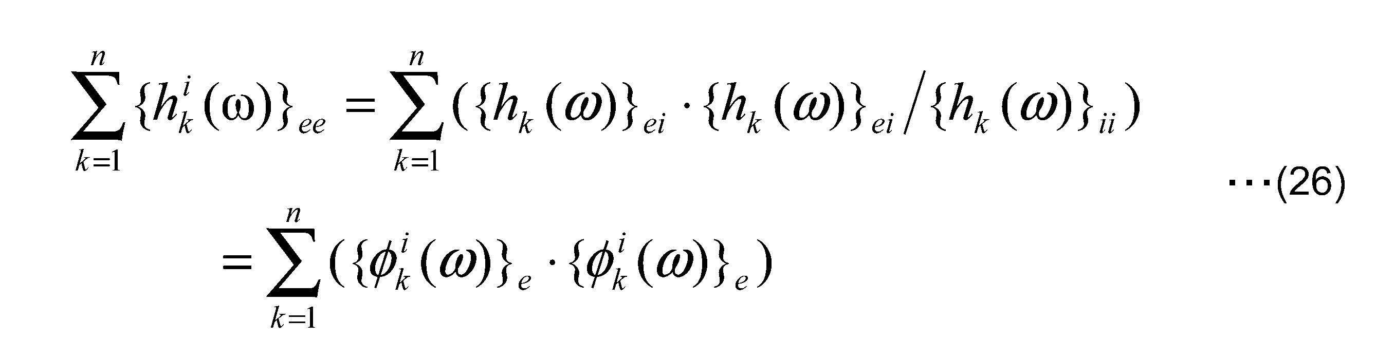
- the subscripts “e 1 e 2 ” and “e 2 e 1 ” indicate off-diagonal terms and have the same meaning as the subscripts “ej” and “je”.
- the 2nd calculation part 222 calculates the force which arises in the connection point e of the response side structure pp at the time of actual operation
- the second calculation unit 222 transmits the response ⁇ U op ⁇ m at the connection point e of the response side structure pp measured in the actual operation of the procedure 1 and the transfer function [G i on the vector space [H] estimated in the procedure 2.
- the force ⁇ F i-op ⁇ n generated at all connection points e in actual operation on the vector space [H] is calculated.
- the response at the connection point e is preferably data correlated with the evaluation point, such as data obtained by cross-power spectrum conversion based on the evaluation point criterion.
- the third calculation unit 224 calculates the contribution of the transmission path to the evaluation physical quantity (sound ⁇ P a ⁇ i , vibration ⁇ U op ⁇ i, etc.) at the evaluation point i by summing up the multiplied values.
- the ratio of the multiplication value at a predetermined connection point to the total is the contribution of the transmission path at that connection point.
- volume acceleration excitation ⁇ q ⁇ i using a speaker is performed at the evaluation point.
- a vibration exciter is used.
- the measurement acceleration response ⁇ u ⁇ i For vibration evaluation
- sound pressure response ⁇ p a ⁇ i at evaluation point i vicinity Is done.
- the volume acceleration excitation ⁇ q ⁇ i using the speaker is performed at the evaluation point. Is called.
- a vibration exciter is used.
- the acceleration ⁇ u ⁇ n is measured at the connection point e of the response side structure pp, and the strain ⁇ n near the connection point e is further measured.
- the evaluation point sound pressure response with i vicinity ⁇ p a ⁇ i is measured.
- the transfer function ⁇ h ⁇ ei to the evaluation point i is measured from the acceleration response of the connection point e and the nearby strain response, and at the same time, the driving point function ⁇ h ⁇ ii at the same position i as the evaluation point is measured.
- the information processing apparatus 20 can solve the two problems of the conventional method by using the estimated transfer function, Expression (19), and Expression (20). Specifically, according to the embodiment, the contribution analysis of the transmission path can be performed without being separated into partial structures, and all the necessary results can be obtained by one measurement. One problem can be solved.
- the measured data is once converted to other coordinate axes such as the frequency axis and analyzed. .
- input and contribution are calculated
- FIG. 5 is a flowchart illustrating an example of a transmission path analysis process in the first embodiment.
- step S102 the input unit 212 inputs the measured transfer function ⁇ h ⁇ ei (each first transfer function) and the drive point function ⁇ h ⁇ ii (first self-transfer function).
- step S104 the first estimation unit 214 uses the first self-transfer function and each first transfer function to perform each first connection at each connection point on the vector space based on the transfer function between the connection point and the evaluation point. 2 Estimate the self-transfer function ⁇ h i ⁇ ee .
- step S106 the first calculation unit 216 uses the second self-transfer function estimated by the first estimation unit 214 for the self-transfer function defined as the inner product of the input-side element vector and the output-side element vector.
- the element vector of each connection point is calculated.
- step S108 the second estimation unit 218 estimates each second transfer function between the connection points on the vector space using the element vector of each connection point.
- step S110 the construction unit 220 constructs a third transfer function at each connection point of the response-side structure pp on the vector space using each second self-transfer function and each second transfer function. Thereby, the separation man-hour to the partial structure and the measurement man-hour of the transfer function can be reduced, and an appropriate transfer function can be estimated.
- the inventors have conducted two experiments.
- the first is a simulation experiment using a complex vehicle model that simulates the phenomenon of a vehicle running experiment in order to reproduce an experiment under ideal conditions without any disturbance (FIGS. 6 and 7).
- the sound in the passenger compartment when a displacement input is applied to the tire ground contact surface is calculated in order to reproduce the phenomenon during traveling.
- the second is a measurement experiment when running on the road using an actual vehicle with various disturbances (FIGS. 8 and 9).
- FIG. 6 is a diagram showing a simulation result (numerical analysis) using a complicated vehicle model by the transmission path analysis of the conventional method.
- the conventional method shown in FIG. 6 is a method of measuring a response by performing decomposition into partial structures, inputting from a connection point side.
- the solid line shown in FIG. 6 is the calculation data of the sound in the passenger compartment when the displacement input is given to the tire ground contact surface in order to reproduce the phenomenon at the time of traveling, and the thin line is the result analyzed by the conventional method It is the simulation result data which shows.
- the calculation data of the solid line and the simulation result data of the thin line are almost the same, and it can be seen that the analysis of the conventional method is appropriately performed.
- FIG. 7 is a diagram illustrating a simulation result using a complicated vehicle model by the transmission path analysis of the embodiment.
- the method of the embodiment shown in FIG. 7 is a method of reducing man-hours by estimating the self-transfer function at the evaluation point, unlike the conventional method, in which the input is performed from the evaluation point side and the response is measured.
- the solid line shown in FIG. 7 is the same calculation data as the solid line shown in FIG. 6, and the thin line is the simulation result data showing the result analyzed by the method of the example.
- the transmission path analysis method in this embodiment greatly reduces the separation man-hours and the measurement man-hours. Analysis can be performed with the same high accuracy as the conventional method.
- FIG. 8 is a diagram showing actual vehicle experiment data for explaining comparison of sound pressures when parts are replaced.
- the solid line shown in FIG. 8 shows sound pressure measurement experiment data at the evaluation point of the original automobile.
- the thin line shown in FIG. 8 shows sound pressure measurement experimental data at an evaluation point of an automobile having a suspension different from that of the original. As shown in FIG. 8, the difference in sound pressure is caused by changing the suspension, particularly at 60 to 100 Hz.
- FIG. 9 is a diagram showing simulation result data before and after parts replacement using the transmission path analysis in the embodiment for the automobile described in FIG.
- the solid line shown in FIG. 9 is the simulation result data obtained by performing the transmission path analysis of the embodiment with respect to the original vehicle, and the thin line is the transmission path analysis of the embodiment with respect to the vehicle having a suspension different from that of the original vehicle. Simulation result data.
- FIG. 9 also in the analysis results, there is a difference in sound pressure at 60 to 100 Hz representing the difference in parts. Therefore, according to the transmission path analysis of the embodiment, it is possible to appropriately detect differences in parts.
- the information processing apparatus 10 can reduce the man-hours for separating the partial structure and the measurement man-hour of the transfer function, and can estimate an appropriate transfer function.
- FIG. 10 is a block diagram illustrating an example of functions of the information processing apparatus 20 according to the second embodiment.
- the information processing apparatus 20 illustrated in FIG. 10 includes a calculation unit 300 and a storage unit 202.
- the calculation unit 300 includes an input unit 212, a fourth calculation unit 302, a first estimation unit 214, a first calculation unit 216, a second estimation unit 218, a construction unit 220, a second calculation unit 222, A third calculator 224 at least.
- the fourth calculation unit 302 acquires the first self-transfer function and each first transfer function from the input unit 212.
- the fourth calculation unit 302 performs expression expansion used in general mode analysis on the frequency response function at the connection point on the vector space based on the transfer function between the connection point and the evaluation point.
- the fourth calculation unit 302 develops the frequency response function using Equation (22) using mode analysis.
- the frequency response function on the left side of Equation (22) can be expressed by the sum of the equations represented by the variables of the kth mode coordinate system and the remainder function of the second term on the right side, as in the first term on the right side. it can.
- k is the mode number
- ⁇ dk is the attenuation natural frequency
- ⁇ k is the stimulation coefficient
- ⁇ k ⁇ is the mode type [Z r ] is the remainder term
- the fourth calculation unit 302 treats the remainder function term of the second term on the right side of Equation (22) in the same manner as the superposition of the frequency responses of the mode coordinate systems of the first term on the right side, and represents the frequency response represented by each term. Superimpose functions. Thereby, the frequency response function can be expressed by the equation (23).
- the following formulas are all developed assuming the frequency response function of formula (23). Thereafter, with the use of Expression (23), the expression of the first embodiment is changed to an expression that expresses each frequency response h by adding a subscript k.
- Expression (23) is an expression expressing the frequency response by superposing frequency responses with one degree of freedom.
- the first estimator 214 uses the following formula to calculate each first point at each connection point on the vector space based on the transfer function between the connection point and the evaluation point, as in the first embodiment. 2 Calculate the self-transfer function.
- the 1st calculation part 216 calculates the element vector of each connection point using the following formula
- the 2nd estimation part 218 estimates each 2nd transfer function between connection points using the following formula
- the construction unit 220 uses the equation (38) to calculate the drive point functions ⁇ h i ⁇ ee and transfer functions ⁇ h i ⁇ for all estimated connection points e.
- the transfer function at the connection point e of the response side structure pp is constructed on the vector space [H].
- the second calculation unit 222 calculates the force generated at the connection point e of the response side structure pp at the time of actual operation of a product such as an automobile, using the equation (39), as in the first embodiment. .
- the third calculation unit 224 sums up the multiplied values using the equation (40), so that the evaluation physical quantity (sound ⁇ P a ⁇ i and vibration ⁇ U op ⁇ i etc.) is calculated.
- FIG. 11 is a diagram for explaining a simple model used in the second embodiment.
- FIG. 11 is constructed to demonstrate the effectiveness of the present method by comparing the transfer function previously calculated by the finite element method and the transfer function estimated using the present method in order to prove the accuracy of the present method. The model is shown.
- the model shown in FIG. 11 uses a two-dimensional beam model representation based on the theory of the finite element method.
- two degrees of freedom of translation and rotation are a set, and what connects each set of the two degrees of freedom is called an element.
- This element constitutes a beam.
- element numbers are not described, but only degrees of freedom are described. Odd numbers represent translational degrees of freedom, and even numbers represent rotational degrees of freedom.
- the model shown in FIG. 11 connects to the odd number of translational degrees of freedom at both ends of each beam using translation spring elements.
- the “element” here is a different concept from the “element vector” used in the mathematical expression.
- Fig. 11 shows the input side structure (Active Part) composed of one beam model and two ground spring elements using the finite element method, and the three beam models and each beam with two translation spring elements.
- the response side structure (Passive Part) including the evaluation points connecting degrees 1 and 41, 39 and 79, 41 and 81, 79 and 119 is provided with degrees of freedom 81 and 121, 101 and 141 via three translational spring elements.
- 119 and 159 are connected system models. The results of various experiments by simulation using the model shown in FIG. 11 will be described below.
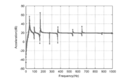
- FIG. 12 is a diagram illustrating an example of an experimental result (No. 1) for evaluating the estimation accuracy of the drive point function in the second embodiment.
- the result shown in FIG. 12 shows that the driving point function at the degree of freedom 81 that is the connection point is directly finite using the model of only the response side structure when the connection springs on the input structure side and the response structure side are not connected.
- the result of a solid line calculated using the element method and the result of a dotted line (a line formed by dots and dots) estimated by this method are shown.
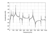
- FIG. 13 is a diagram illustrating an example of an experimental result (No. 2) for evaluating the estimation accuracy of the driving point function in the second embodiment.
- the result shown in FIG. 13 shows that the driving point function at the degree of freedom 101 that is the connection point is directly finite using the model of only the response side structure when the connection springs on the input structure side and the response structure side are not connected.
- the result of the solid line calculated using the element method and the result of the dotted line estimated by this method are shown.
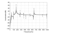
- FIG. 14 is a diagram illustrating an example of an experimental result (part 1) for evaluating the estimation accuracy of the transfer function in the second embodiment.
- the result shown in FIG. 14 shows that the transfer function of the degree of freedom 81 when the degree of freedom 101 is vibrated using the model of only the response side structure when the connection springs of the input structure side and the response structure side are not connected.
- the results of the solid line calculated directly using the finite element method and the result of the dotted line estimated by this method are shown.
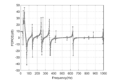
- FIG. 15 is a diagram illustrating an example of an experimental result (part 2) for evaluating the estimation accuracy of the transfer function in the second embodiment.
- the result shown in FIG. 15 shows that the transfer function of the degree of freedom 81 when the degree of freedom 119 is vibrated using a model of only the response side structure when the connection springs of the input structure side and the response structure side are not connected.
- the results of the solid line calculated directly using the finite element method and the result of the dotted line estimated by this method are shown.
- the present method can accurately estimate the driving point function and the transfer function of each degree of freedom.
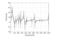
- FIG. 16 is a diagram illustrating an example of an experiment result for evaluating the estimation accuracy of the force generated in the degree of freedom 81 in the second embodiment.
- the result shown in FIG. 16 shows the result of the solid line obtained by directly calculating the force generated in the degree of freedom 81 using the formula (2) of the conventional method and the result of the dotted line estimated using the formula (39).
- FIG. 17 is a diagram illustrating an example of an experiment result for evaluating the estimation accuracy of the force generated in the degree of freedom 101 in the second embodiment.
- the result shown in FIG. 17 shows the result of the solid line obtained by directly calculating the force generated in the degree of freedom 101 using Expression (2) of the conventional method and the result of the dotted line estimated using Expression (39).
- FIG. 18 is a diagram illustrating an example of an experimental result for evaluating the estimation accuracy of the force generated at the degree of freedom 119 in the second embodiment.
- the result shown in FIG. 18 shows the result of the solid line obtained by directly calculating the force generated in the degree of freedom 119 using the formula (2) of the conventional method and the result of the dotted line estimated using the formula (39).
- the present method can accurately estimate the force generated in each degree of freedom.
- FIG. 19 is a diagram illustrating an example of an experimental result for evaluating the estimation accuracy of the evaluation physical quantity of the evaluation point in the second embodiment.
- the results shown in FIG. 19 are the result of the solid line calculated using Equation (1) of the conventional method and the result of the dotted line estimated using Equation (40) as the evaluation physical quantity at the degree of freedom 11 as the evaluation point. It shows.
- the present method can accurately obtain the vibration that is the evaluation physical quantity at the evaluation point.
- the CPU 102 reads the program from the ROM 106 and executes it, so that one or more of the above-described units are loaded on the RAM 104, One or more units are generated on the RAM 104.
- the processing described in the above-described two embodiments may be realized as a program for causing a computer to execute.
- the above-described processing can be realized by installing this program from a server or the like and causing the computer to execute it.
- the recording medium 116 is a recording medium that records information optically, electrically, or magnetically, such as a CD-ROM, a flexible disk, or a magneto-optical disk, and information is electrically stored such as a ROM or flash memory.
- Various types of recording media such as a semiconductor memory for recording can be used.
- the automobile is described as the object, but the transmission path analysis in the embodiment can be applied to a ship, an airplane, a building, and the like.
Landscapes
- Physics & Mathematics (AREA)
- Engineering & Computer Science (AREA)
- General Physics & Mathematics (AREA)
- Theoretical Computer Science (AREA)
- Geometry (AREA)
- Pure & Applied Mathematics (AREA)
- Mathematical Optimization (AREA)
- Mathematical Analysis (AREA)
- Computational Mathematics (AREA)
- General Engineering & Computer Science (AREA)
- Mathematical Physics (AREA)
- Evolutionary Computation (AREA)
- Computer Hardware Design (AREA)
- Data Mining & Analysis (AREA)
- Automation & Control Theory (AREA)
- Algebra (AREA)
- Databases & Information Systems (AREA)
- Software Systems (AREA)
- Aviation & Aerospace Engineering (AREA)
- Manufacturing & Machinery (AREA)
- Human Computer Interaction (AREA)
- Measurement Of Mechanical Vibrations Or Ultrasonic Waves (AREA)
Abstract
Description
課題1:部分構造へ分離するのに莫大な工数が掛かる。
課題2:分離した部分構造の各接続点における駆動点関数(入力点と応答点が同じ位置となる伝達関数)と、接続点間の伝達関数との計測に莫大な工数が掛かる。
<構成>
図1は、第1実施形態における情報処理装置10の概略構成の一例を示すブロック図である。図1に示すように、情報処理装置10は、CPU(Central Processing Unit)102と、RAM(Random Access Memory)104と、ROM(Read only Memory)106と、ドライブ装置108と、ネットワークI/F(Interface)110と、入力装置112と、表示装置114とを有する。これら各構成は、バスを介して相互にデータ送受信可能に接続されている。
次に、情報処理装置10の機能について説明する。図2は、第1実施形態における情報処理装置10の機能の一例を示すブロック図である。図2に示す情報処理装置10は、演算部200と、記憶部202とを備え、演算部200は、入力部212と、第1推定部214と、第1算出部216と、第2推定部218と、構築部220と、第2算出部222と、第3算出部224とを少なくとも備える。
また、記憶部202は、例えばRAM104及び/又はROM106により実現されうる。記憶部202は、伝達経路解析に用いるパラメータや演算結果などを記憶する。ここで、対象物の伝達経路解析を実施する際に、以下の定義が行われる。
対象物に対して、入力側構造と、この入力側構造と1つ以上の接続点を介して接続される、評価点を含む応答側構造という部分構造が定義される。
入力側構造と応答側構造との各接続点に発生する作用反作用の力について、構造を分離した際は、入力側構造と応答側構造とに対する外力として、また構造を分離しないで接続している場合は、内力として定義される。
以下に提案する解析手法は、この各接続点における実稼働時の力を推定し、応答側構造の各接続点eから評価点iまでの伝達関数に掛け合わせ、その総和により、評価点における物理量(例えば、音、振動、歪、電流・電圧など)が近似的に表現できるシステムを対象とする。
対象物の実稼働時に、対象物の評価点iにおいて、対象物の評価が可能な物理量(例えば音や振動など)が計測される。これと同時に、応答側構造の接続点eにおいても、伝達経路の寄与を見積もることが可能な物理量(例えば加速度など)が計測される。
次に、対象物の応答側構造に生ずる力を推定するために、評価点iからの入力に対する評価点iにおける応答が計測される。これと同時に、評価点iからの入力に対する各接続点eにおける応答も計測される。これにより、対象物の伝達経路解析を行う際に計測された、評価点iにおける伝達関数(以下、第1自己伝達関数、駆動点関数ともいう。)や各接続点e間における伝達関数(以下、各第1伝達関数ともいう。)が取得される。
次に、対象物を車両(以下、自動車を例にする)とし、車両の評価が可能な物理量を音や振動とし、接続点において伝達経路の寄与を見積もることが可能な物理量を加速度とする実施例について説明する。本実施例において、以下の定義が行われる。
図3は、実施例における入力側構造と応答側構造の一例を示す図である。自動車に対して伝達経路解析が実施される際、まず、自動車に対して、入力側構造(Active part)apと、評価点を含む応答側構造(Passive part)ppという部分構造が定義される。
次に、入力側構造apと応答側構造ppの各接続点e1、e2に発生する作用反作用の力について、構造を分離した場合は、入力側構造apと応答側構造ppに対する外力、また構造を分離しない場合は、入力側構造apと応答側構造ppに対する内力として定義される。
本実施例において、発明者らは、評価点iにおける音を、伝達関数[H]inと実稼働時の力{Fop}nを用いて式(1)で表す。

次に、実施例において、応答側構造ppの各接続点eにおける伝達経路解析を実施するために、以下の手順が行われる。
まず、自動車の実稼働時に、対象物の評価点iにおいて製品の評価が可能な音{Pa}iや振動{Uop}i(Uは、ウムラウト付きUを表す)がセンサーにより計測される。この計測と同時に、応答側構造ppの接続点eにおいても伝達経路の寄与を見積もることが可能な加速度{Uop}mが計測される。この時、計測する個数mは、求めたい力の個数n以上(m≧n)となることが望ましい。
実施例における手順2を説明する前に、実施例と比較するための、従来手法の処理について説明する。


次に、実施例の手順2について説明する。実施例では、従来手法とは異なり、[G]mnは計測されず、発明者らにより提案される後述の式を用いることで、伝達経路解析に必要な評価点iに寄与する駆動点関数{hi(k)}eeと、接続点e間の伝達関数{h}ejとが推定される。kは、周波数などの刻みステップである。これにより、実施例では、駆動点関数や伝達関数を適切に推定するため、計測工数を大幅に削減することができる。








次に、第2推定部218は、手順3で算出した応答側構造ppの複数の非加振点である接続点eにおける要素ベクトル{Φi}eを用いて、ベクトル空間[H]上の全ての接続点間の伝達関数{hi}ejを、式(15)~(17)を用いて推定する。



次に、第2算出部222は、自動車の実稼働時における応答側構造ppの接続点eに生ずる力を算出する。第2算出部222は、手順1の実稼働時に計測した応答側構造ppの接続点eにおける応答{Uop}mと、手順2で推定されたベクトル空間[H]上の伝達関数[Gi]eeとを用いて、ベクトル空間[H]上の実稼働時の全接続点eに生ずる力{Fi-op}nを算出する。なお、接続点eにおける応答は、評価点基準でクロスパワースペクトル化したデータなど、評価点と相関があるデータが望ましい。

次に、第3算出部224は、手順2で評価点側から加振して計測した評価点iと、応答側構造ppの各接続点eの間の伝達関数{h}eiを、相反性を利用して各接続点e側から評価点iへの伝達関数という逆伝達関数としてまとめて構築した行列[H]inに対して、手順4で求めた力{Fi-op}nを掛け合わせる。第3算出部224は、乗算した値を総和することで、評価点iにおける評価物理量(音{Pa}iや振動{Uop}iなど)に対する伝達経路の寄与を算出する。所定の接続点における乗算値が総和に占める割合が、その接続点における伝達経路の寄与となる。

ここで、上述した実施例における各手順について、事例を用いて説明する。例えば、自動車の評価は、評価点iにおいて音{Pa}i(振動評価の場合は加速度{Uop}i)とする。また、伝達経路の寄与解析を実施する応答側構造の接続点eにおける計測結果は、振動の加速度{Uop}mとする。
情報処理装置10の動作について説明する。図5は、第1実施形態における伝達経路解析処理の一例を示すフローチャートである。
以下、発明者らは、2つの実験を実施している。一つ目は、全く外乱が無い理想的な条件の実験を再現するために、車両走行実験の現象を模擬する複雑な車両モデルを用いたシミュレーション実験である(図6、7)。このシミュレーション実験では、走行時の現象を再現するため、タイヤ接地面に対し、変位入力を与えた時の車室内の音が計算される。二つ目は、さまざまな外乱がある条件の実車を使った路面走行時の計測実験である(図8、図9)。
次に、第2実施形態における情報処理装置について説明する。第2実施形態における情報処装置の構成は、図1に示す構成と同様であるため、その説明を省略する。
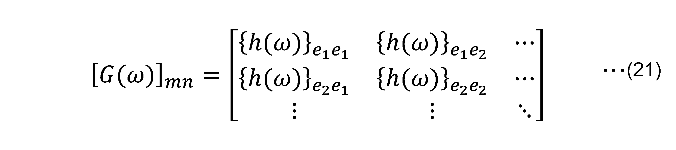
図10は、第2実施形態における情報処理装置20の機能の一例を示すブロック図である。図10に示す機能のうち、図2に示す機能と同様のものは、図2に示す符号と同じ符号を用いる。図10に示す情報処理装置20は、演算部300と、記憶部202とを備える。演算部300は、入力部212と、第4算出部302と、第1推定部214と、第1算出部216と、第2推定部218と、構築部220と、第2算出部222と、第3算出部224とを少なくとも備える。

kは、モード数
ωdkは、減衰自然周波数
ξkは、刺激係数
{φk}は、モード形
[Zr]は、剰余項












第2実施形態における情報処理装置20の動作について説明する。第2実施形態における情報処理装置20の動作は、図5に示すステップS102とS104と間に第4算出部302によるモード解析処理が挿入される。第2実施形態におけるステップS104以降の処理は、モード解析により得られた周波数応答関数が展開されること以外は、図5で説明した処理と同様である。
102 CPU
104 RAM
106 ROM
212 入力部
214 第1推定部
216 第1算出部
218 第2推定部
220 構築部
222 第2算出部
224 第3算出部
302 第4算出部
Claims (7)
- 対象物の伝達経路解析を行う際、該対象物に対して入力側構造と、該入力側構造と1つ以上の接続点を介して接続される、評価点を含む応答側構造とが定義され、前記評価点からの入力に対する該評価点における応答を計測して取得される第1自己伝達関数と、前記入力に対する各接続点間における応答を計測して取得される各第1伝達関数とを入力する入力部と、
前記第1自己伝達関数及び前記各第1伝達関数を用いて、前記接続点と前記評価点との間の伝達関数に基づくベクトル空間上の各接続点における各第2自己伝達関数を推定する第1推定部と、
入力側の要素ベクトルと出力側の要素ベクトルの内積として定義される自己伝達関数に対し、前記第1推定部により推定された各第2自己伝達関数に基づき、各接続点の要素ベクトルを算出する第1算出部と、
前記各接続点の要素ベクトルを用いて、前記ベクトル空間上の接続点間の各第2伝達関数を推定する第2推定部と、
前記各第2自己伝達関数と、前記各第2伝達関数とを用いて、前記ベクトル空間上における前記応答側構造の各接続点における第3伝達関数を構築する構築部と、
を備える情報処理装置。 - 前記第1推定部は、
前記第1自己伝達関数及び前記各第1伝達関数に対し、オイラーの公式を用いて代入して推定処理を行う、請求項1記載の情報処理装置。 - 前記対象物の稼働時に計測した、前記応答側構造の各接続点における応答データと、前記第3伝達関数とを用いて、前記ベクトル空間上の稼働時の各接続点に生ずる力を算出する第2算出部と、
前記各接続点における第1伝達関数に、対応する接続点に生ずる力を乗算して総和を求め、前記評価点における評価物理量に対する伝達経路の寄与を算出する第3算出部と、
をさらに備える、請求項1又は2に記載の情報処理装置。 - 前記入力部に入力された前記第1自己伝達関数及び前記各第1伝達関数に基づく、前記接続点と前記評価点との間の伝達関数に基づくベクトル空間上の各接続点における周波数応答関数に対し、モード解析を行う第4算出部をさらに備え、
前記第1推定部は、
前記第4算出部によりモード解析された周波数応答関数に基づく各第2自己伝達関数を推定する、請求項1乃至3いずれか一項に記載の情報処理装置。 - 対象物の伝達経路解析を行う際、該対象物に対して入力側構造と、該入力側構造と1つ以上の接続点を介して接続される、評価点を含む応答側構造とが定義され、前記評価点からの入力に対する該評価点における応答を計測して取得される第1自己伝達関数と、前記入力に対する各接続点における応答を計測して取得される各第1伝達関数とを入力すること、
前記第1自己伝達関数及び前記各第1伝達関数を用いて、前記評価点が存在するベクトル空間上の各接続点における各第2自己伝達関数を推定すること、
前記ベクトル空間の前記各第2自己伝達関数を用いて、各接続点の要素ベクトルを算出すること、
前記各接続点の要素ベクトルを用いて、前記ベクトル空間上の全ての接続点間の各第2伝達関数を推定すること、
前記各第2自己伝達関数と、前記各第2伝達関数とを用いて、前記ベクトル空間上における前記応答側構造の各接続点における第3伝達関数を構築すること、
をコンピュータが実行する情報処理方法。 - 請求項5に記載の情報処理方法をコンピュータに実行させるためのプログラム。
- 請求項6に記載のプログラムを記録したコンピュータ読み取り可能な記録媒体。
Priority Applications (3)
| Application Number | Priority Date | Filing Date | Title |
|---|---|---|---|
| US15/321,799 US20170185066A1 (en) | 2014-06-27 | 2015-06-12 | Information processing device, information processing method, program, and recording medium |
| EP15811793.7A EP3163270A4 (en) | 2014-06-27 | 2015-06-12 | Information processing device, information processing method, program, and recording medium |
| JP2016529316A JPWO2015198894A1 (ja) | 2014-06-27 | 2015-06-12 | 情報処理装置、情報処理方法、プログラム及び記録媒体 |
Applications Claiming Priority (2)
| Application Number | Priority Date | Filing Date | Title |
|---|---|---|---|
| JP2014133142 | 2014-06-27 | ||
| JP2014-133142 | 2014-06-27 |
Publications (1)
| Publication Number | Publication Date |
|---|---|
| WO2015198894A1 true WO2015198894A1 (ja) | 2015-12-30 |
Family
ID=54937985
Family Applications (1)
| Application Number | Title | Priority Date | Filing Date |
|---|---|---|---|
| PCT/JP2015/067051 Ceased WO2015198894A1 (ja) | 2014-06-27 | 2015-06-12 | 情報処理装置、情報処理方法、プログラム及び記録媒体 |
Country Status (4)
| Country | Link |
|---|---|
| US (1) | US20170185066A1 (ja) |
| EP (1) | EP3163270A4 (ja) |
| JP (1) | JPWO2015198894A1 (ja) |
| WO (1) | WO2015198894A1 (ja) |
Cited By (1)
| Publication number | Priority date | Publication date | Assignee | Title |
|---|---|---|---|---|
| JP2022076701A (ja) * | 2020-11-10 | 2022-05-20 | トヨタ自動車株式会社 | 車両の異音検査装置 |
Families Citing this family (3)
| Publication number | Priority date | Publication date | Assignee | Title |
|---|---|---|---|---|
| CN112595528B (zh) * | 2020-08-24 | 2022-06-17 | 中国汽车技术研究中心有限公司 | 车辆行驶工况下动力总成悬置主动侧激励力的识别方法 |
| CN112697448B (zh) * | 2020-08-24 | 2022-06-17 | 中国汽车技术研究中心有限公司 | 车辆怠速工况下动力总成悬置主动侧激励力的识别方法 |
| CN115144033A (zh) * | 2022-07-08 | 2022-10-04 | 重庆大学 | 时域工况传递路径分析方法 |
Citations (2)
| Publication number | Priority date | Publication date | Assignee | Title |
|---|---|---|---|---|
| JP2010230584A (ja) * | 2009-03-27 | 2010-10-14 | Mazda Motor Corp | 車両の音響解析装置 |
| JP2011081543A (ja) * | 2009-10-06 | 2011-04-21 | Suzuki Motor Corp | 寄与度解析方法及び装置 |
Family Cites Families (3)
| Publication number | Priority date | Publication date | Assignee | Title |
|---|---|---|---|---|
| AT504424B1 (de) * | 2008-02-08 | 2009-05-15 | Avl List Gmbh | Verfahren zur bestimmung der anteile einzelner übertragungswege |
| EP2113755B1 (en) * | 2008-05-01 | 2012-02-01 | LMS International NV | Vibrational and/or acoustic transfer path analysis |
| US20130083929A1 (en) * | 2011-09-30 | 2013-04-04 | Hitachi, Ltd. | Method for analyzing sound transmission paths in a system |
-
2015
- 2015-06-12 EP EP15811793.7A patent/EP3163270A4/en not_active Withdrawn
- 2015-06-12 WO PCT/JP2015/067051 patent/WO2015198894A1/ja not_active Ceased
- 2015-06-12 US US15/321,799 patent/US20170185066A1/en not_active Abandoned
- 2015-06-12 JP JP2016529316A patent/JPWO2015198894A1/ja active Pending
Patent Citations (2)
| Publication number | Priority date | Publication date | Assignee | Title |
|---|---|---|---|---|
| JP2010230584A (ja) * | 2009-03-27 | 2010-10-14 | Mazda Motor Corp | 車両の音響解析装置 |
| JP2011081543A (ja) * | 2009-10-06 | 2011-04-21 | Suzuki Motor Corp | 寄与度解析方法及び装置 |
Non-Patent Citations (1)
| Title |
|---|
| See also references of EP3163270A4 * |
Cited By (2)
| Publication number | Priority date | Publication date | Assignee | Title |
|---|---|---|---|---|
| JP2022076701A (ja) * | 2020-11-10 | 2022-05-20 | トヨタ自動車株式会社 | 車両の異音検査装置 |
| JP7392633B2 (ja) | 2020-11-10 | 2023-12-06 | トヨタ自動車株式会社 | 車両の異音検査装置 |
Also Published As
| Publication number | Publication date |
|---|---|
| EP3163270A1 (en) | 2017-05-03 |
| EP3163270A4 (en) | 2018-04-18 |
| US20170185066A1 (en) | 2017-06-29 |
| JPWO2015198894A1 (ja) | 2017-04-20 |
Similar Documents
| Publication | Publication Date | Title |
|---|---|---|
| Cumbo et al. | Kalman-based load identification and full-field estimation analysis on industrial test case | |
| Janssens et al. | OPAX: A new transfer path analysis method based on parametric load models | |
| EP2113755B1 (en) | Vibrational and/or acoustic transfer path analysis | |
| CN105631090A (zh) | 一种有限元模型优化装置及方法 | |
| Dragos et al. | Decentralized infrastructure health monitoring using embedded computing in wireless sensor networks | |
| WO2015198894A1 (ja) | 情報処理装置、情報処理方法、プログラム及び記録媒体 | |
| JP6477411B2 (ja) | 解析プログラム | |
| Wang et al. | An improved OPAX method based on moving multi-band model | |
| Mayes et al. | Predicting system response at unmeasured locations | |
| US20250094660A1 (en) | Methods and systems of determining the static stiffness of a body structure | |
| CN105705927A (zh) | 具有柔性致动器组件和迭代获得的驱动的测试系统 | |
| Sahu et al. | Experimental modal analysis of a tire: an exploration of different operating and boundary conditions | |
| CN117171886B (zh) | 一种车身复合振动识别方法、装置、设备及存储介质 | |
| Gajdátsy | Advanced transfer path analysis methods | |
| Ragnarsson et al. | Subcomponent modelling of input parameters for statistical energy analysis by using a wave-based boundary condition | |
| JP2021012605A (ja) | 伝達関数の予測方法 | |
| CN118673651A (zh) | 悬置动刚度曲线仿真方法、装置、电子设备及存储介质 | |
| JP4232566B2 (ja) | 有限要素による数値解析における形状把握方法 | |
| Ramos et al. | Kalman-based force identification applied to vibration transfer path analysis | |
| Gibanica | Experimental-analytical dynamic substructuring: a state-space approach | |
| US6804615B2 (en) | Method of estimating system dynamics by subsystem transfer function testing | |
| Yoon et al. | Transient quasi-static Ritz vector (TQSRV) method by Krylov subspaces and eigenvectors for efficient contact dynamic finite element simulation | |
| CN113704870A (zh) | 发动机激振力识别方法、装置、计算机设备和存储介质 | |
| Elkafafy et al. | Optimizing NVH Performance in Electric Vehicles Through Enhanced Modal Parameter Estimation Techniques | |
| Allen et al. | Industrial Applications & Related Concepts |
Legal Events
| Date | Code | Title | Description |
|---|---|---|---|
| 121 | Ep: the epo has been informed by wipo that ep was designated in this application |
Ref document number: 15811793 Country of ref document: EP Kind code of ref document: A1 |
|
| ENP | Entry into the national phase |
Ref document number: 2016529316 Country of ref document: JP Kind code of ref document: A |
|
| NENP | Non-entry into the national phase |
Ref country code: DE |
|
| REEP | Request for entry into the european phase |
Ref document number: 2015811793 Country of ref document: EP |
|
| WWE | Wipo information: entry into national phase |
Ref document number: 2015811793 Country of ref document: EP |
|
| WWE | Wipo information: entry into national phase |
Ref document number: 15321799 Country of ref document: US |