WO2016002045A1 - 質量分析装置 - Google Patents
質量分析装置 Download PDFInfo
- Publication number
- WO2016002045A1 WO2016002045A1 PCT/JP2014/067791 JP2014067791W WO2016002045A1 WO 2016002045 A1 WO2016002045 A1 WO 2016002045A1 JP 2014067791 W JP2014067791 W JP 2014067791W WO 2016002045 A1 WO2016002045 A1 WO 2016002045A1
- Authority
- WO
- WIPO (PCT)
- Prior art keywords
- standard sample
- sample
- measurement
- mass spectrometer
- measurement sample
- Prior art date
- Legal status (The legal status is an assumption and is not a legal conclusion. Google has not performed a legal analysis and makes no representation as to the accuracy of the status listed.)
- Ceased
Links
Images


Classifications
-
- H—ELECTRICITY
- H01—ELECTRIC ELEMENTS
- H01J—ELECTRIC DISCHARGE TUBES OR DISCHARGE LAMPS
- H01J49/00—Particle spectrometers or separator tubes
- H01J49/0009—Calibration of the apparatus
-
- G—PHYSICS
- G01—MEASURING; TESTING
- G01N—INVESTIGATING OR ANALYSING MATERIALS BY DETERMINING THEIR CHEMICAL OR PHYSICAL PROPERTIES
- G01N30/00—Investigating or analysing materials by separation into components using adsorption, absorption or similar phenomena or using ion-exchange, e.g. chromatography or field flow fractionation
- G01N30/02—Column chromatography
- G01N30/62—Detectors specially adapted therefor
- G01N30/72—Mass spectrometers
- G01N30/7233—Mass spectrometers interfaced to liquid or supercritical fluid chromatograph
- G01N30/724—Nebulising, aerosol formation or ionisation
-
- H—ELECTRICITY
- H01—ELECTRIC ELEMENTS
- H01J—ELECTRIC DISCHARGE TUBES OR DISCHARGE LAMPS
- H01J49/00—Particle spectrometers or separator tubes
- H01J49/02—Details
- H01J49/04—Arrangements for introducing or extracting samples to be analysed, e.g. vacuum locks; Arrangements for external adjustment of electron- or ion-optical components
- H01J49/0422—Arrangements for introducing or extracting samples to be analysed, e.g. vacuum locks; Arrangements for external adjustment of electron- or ion-optical components for gaseous samples
-
- H—ELECTRICITY
- H01—ELECTRIC ELEMENTS
- H01J—ELECTRIC DISCHARGE TUBES OR DISCHARGE LAMPS
- H01J49/00—Particle spectrometers or separator tubes
- H01J49/02—Details
- H01J49/04—Arrangements for introducing or extracting samples to be analysed, e.g. vacuum locks; Arrangements for external adjustment of electron- or ion-optical components
- H01J49/0431—Arrangements for introducing or extracting samples to be analysed, e.g. vacuum locks; Arrangements for external adjustment of electron- or ion-optical components for liquid samples
- H01J49/0445—Arrangements for introducing or extracting samples to be analysed, e.g. vacuum locks; Arrangements for external adjustment of electron- or ion-optical components for liquid samples with means for introducing as a spray, a jet or an aerosol
-
- H—ELECTRICITY
- H01—ELECTRIC ELEMENTS
- H01J—ELECTRIC DISCHARGE TUBES OR DISCHARGE LAMPS
- H01J49/00—Particle spectrometers or separator tubes
- H01J49/02—Details
- H01J49/10—Ion sources; Ion guns
- H01J49/14—Ion sources; Ion guns using particle bombardment, e.g. ionisation chambers
- H01J49/145—Ion sources; Ion guns using particle bombardment, e.g. ionisation chambers using chemical ionisation
-
- H—ELECTRICITY
- H01—ELECTRIC ELEMENTS
- H01J—ELECTRIC DISCHARGE TUBES OR DISCHARGE LAMPS
- H01J49/00—Particle spectrometers or separator tubes
- H01J49/02—Details
- H01J49/10—Ion sources; Ion guns
- H01J49/16—Ion sources; Ion guns using surface ionisation, e.g. field-, thermionic- or photo-emission
- H01J49/165—Electrospray ionisation
-
- G—PHYSICS
- G01—MEASURING; TESTING
- G01N—INVESTIGATING OR ANALYSING MATERIALS BY DETERMINING THEIR CHEMICAL OR PHYSICAL PROPERTIES
- G01N30/00—Investigating or analysing materials by separation into components using adsorption, absorption or similar phenomena or using ion-exchange, e.g. chromatography or field flow fractionation
- G01N30/02—Column chromatography
- G01N30/62—Detectors specially adapted therefor
- G01N2030/626—Detectors specially adapted therefor calibration, baseline
Definitions
- the present invention relates to a chromatograph mass spectrometer that performs qualitative analysis / quantitative analysis by chromatography using a mass spectrometer such as a gas chromatograph mass spectrometer or a liquid chromatograph mass spectrometer as a detector, and more particularly, a chromatograph mass spectrometer.
- the present invention relates to a method for calibrating a mass spectrometric unit.
- the liquid chromatograph mass spectrometer includes a liquid chromatograph unit (LC unit) that separates and elutes a liquid sample into components, and an ionization chamber (interface unit) that ionizes sample components eluted from the LC unit. ) And a mass analysis unit (MS unit) that detects ions introduced from the ionization chamber.
- LC unit liquid chromatograph unit
- ionization chamber interface unit
- MS unit mass analysis unit
- MS unit mass analysis unit
- various ionization methods are used to ionize sample components, but atmospheric pressure ionization methods such as atmospheric pressure chemical ionization (APCI) and electrospray ionization (ESI) are widely used. It has been.
- the tip of the nozzle connected to the end of the column of the LC section is arranged toward the inside of the ionization chamber, and a needle electrode is arranged in front of the tip of the nozzle.
- generated by the corona discharge from a needle electrode is chemically reacted with the droplet of the sample atomized by the heating in the nozzle, and is ionized.
- the tip of the nozzle connected to the end of the column of the LC section is arranged toward the inside of the ionization chamber, and a high unequal electric field is applied by applying a high voltage of about several kV to the tip of the nozzle. Is generated.
- the sample components are charge-separated by the electric field and are torn off by the Coulomb attractive force to be atomized.
- the solvent in the droplets of the sample evaporates and gas ions are generated.
- sample components are ionized in a state close to atmospheric pressure, so an ionization chamber in a high pressure state (that is, a state close to atmospheric pressure) and a very low pressure state (that is, a state of high vacuum).
- a configuration is adopted in which an intermediate chamber or the like is provided between the ionization chamber and the MS portion so that the degree of vacuum is gradually increased.
- FIG. 4 is a schematic configuration diagram illustrating an example of a liquid chromatograph mass spectrometer using the ESI method.
- the front direction parallel to the ground is defined as the X direction
- the direction horizontal to the ground and perpendicular to the X direction is defined as the Y direction
- the direction perpendicular to the X direction and the Y direction is defined as the Z direction.
- the liquid chromatograph mass spectrometer 201 includes an LC unit 2, a probe (ion source) 15, an ionization chamber 11 including a chamber (housing) 210, a first intermediate chamber 12 adjacent to the ionization chamber 11, a first A second intermediate chamber 13 adjacent to the intermediate chamber 12, a mass analysis chamber (MS unit) 14 adjacent to the second intermediate chamber 13, and a computer 240 that controls the entire liquid chromatograph mass spectrometer 201 are provided.
- FIG. 5A is a side view of the probe
- FIG. 5B is an enlarged cross-sectional view of A shown in FIG.
- the probe 15 has a double tube structure, and the measurement sample supplied via the measurement sample channel 155 is ejected from the inside of the circular tube 151.
- the nitrogen gas supplied from the nebulization gas channel 156 is injected from between the circular tube 151 and the circular tube-shaped nozzle 152.
- the ejected measurement sample is sprayed in a mist state due to the collision with the nebulization gas sprayed around the circular tube 151.
- wiring is connected to the tip of the nozzle 152 so that a high voltage of several kV is applied from a voltage source, and ionization is performed by such a configuration.
- the ionization chamber 11 includes a rectangular parallelepiped chamber 210 of 13 cm ⁇ 13 cm ⁇ 12 cm, and the chamber 210 has an upper surface, a partition wall (rear surface), a front surface, a right side surface, a left side surface, and a lower surface.
- the inner space of the ionization chamber 11 is formed by being surrounded by the upper surface, the partition wall, the front surface, the right side surface, the left side surface, and the lower surface.
- a circular opening that communicates in the front-rear direction (X direction) is formed on the front surface, and the probe 15 is attached to the opening.
- the partition wall is arranged so as to partition the inside of the ionization chamber 11 and the inside of the first intermediate chamber 12, and the partition wall has a circular tube shape (diameter outer diameter 1.6 mm, inner diameter 0.5 mm) desolvation tube (ion introduction) Mouth) 19 is formed, and a dry gas flow path 50 is formed so as to cover the periphery of the desolvation tube 19.
- the desolvation tube 19 has a function of promoting desolvation and ionization by heating action and collision action when ions sprayed by the probe 15 and fine sample droplets pass through the inside.
- the jet port of the probe 15 is directed forward (X direction) so as to face the entrance of the desolvation tube 19 with a predetermined distance (for example, 2 cm).
- a drain 30 is formed on the lower surface, and unnecessary samples are discharged from the drain 30 to the outside.
- a first ion lens 21 is provided inside the first intermediate chamber 12, and an exhaust port 31 for evacuating with an oil rotary pump (RP) is provided on the lower surface of the first intermediate chamber 12.
- RP oil rotary pump
- a skimmer 22 having a pore (orifice) is formed in the partition wall between the first intermediate chamber 12 and the second intermediate chamber 13, and the inside of the first intermediate chamber 12 and the second space are formed through the pore.
- the interior of the intermediate chamber 13 communicates.
- An octopole 23 and a focus lens 24 are provided inside the second intermediate chamber 13, and an exhaust port 32 for evacuating with a turbo molecular pump (TMP) is provided on the lower surface of the second intermediate chamber 13. It has been.
- TMP turbo molecular pump
- an entrance lens 25 having a pore is provided in a partition wall between the second intermediate chamber 13 and the mass spectrometry chamber 14, and the inside of the second intermediate chamber 13 and the mass spectrometry chamber 14 are interposed through the pore. Communication with the inside.
- a first quadrupole 16, a second quadrupole 17, and a detector 18 are provided inside the mass analysis chamber 14, and the lower surface of the mass analysis chamber 14 is vacuumed by a turbo molecular pump (TMP).
- TMP turbo molecular pump
- An exhaust port 33 for exhausting is provided.
- the ion lens 21, the octopole 23, the focus lens 24, and the entrance lens 25 efficiently send ions that pass under the respective ion velocities to the next stage under respective vacuum conditions. Has a convergence effect.
- ions generated in the ionization chamber 11 are removed from the desolvation tube 19, the first ion lens 21 in the first intermediate chamber 12, the skimmer 22, and the octave in the second intermediate chamber 13. It passes through the pole 23, the focus lens 24, and the entrance lens 25 in this order and is sent to the mass spectrometry chamber 14, and is separated by the quadrupoles 16 and 17 according to the magnitude of the mass-to-charge ratio (m / z) and reaches the detector 18. Will do.
- the computer 240 acquires an intensity signal corresponding to the number of ions generated for each mass-to-charge ratio (m / z) and creates a mass spectrum.
- the molecular weight of the measurement sample is calculated from the mass-to-charge ratio (m / z) at which the peak of the molecular ion appears in the mass spectrum.
- the cleavage mode is estimated from the mass-to-charge ratio (m / z) at which the peak of each fragment ion generated by the cleavage of the molecular ion appears, and the molecular structure of the measurement sample is analyzed.
- the mass-to-charge ratio (m / z) of each peak obtained by measurement of the measurement sample is within a predetermined period. It is determined using a peak obtained by measuring a known standard sample (calibration sample) (see, for example, Patent Document 1).
- the difference (calibration value) between the measured value of the mass-to-charge ratio (m / z) of each peak obtained by measuring the standard sample and the theoretical value of the mass-to-charge ratio (m / z) of the peak ) are calculated, and a calibration value at an arbitrary mass-to-charge ratio (m / z) is obtained by interpolating or extrapolating the plurality of calibration values. Then, by adding the calibration value to the measured value of the peak mass-to-charge ratio (m / z) obtained by measuring the measurement sample, the accurate mass-to-charge ratio (m / z) of each peak is calculated. Yes.
- a method of introducing a standard sample by temporal separation into the measurement sample channel 155 see, for example, Patent Document 2
- a method of preparing a plurality of ion devices and mechanically switching the introduction direction for example, And a method of introducing a standard sample into a vacuum from another flow path different from the measurement sample flow path 155.
- a standard sample channel for spraying the standard sample is formed inside the ionization chamber, a pulse valve is arranged in the standard sample channel, and the standard sample is intermittently introduced using the pulse valve. did.
- the mass spectrometer of the present invention includes an ionization chamber that ionizes a sample, and a mass analysis unit into which ions are introduced from the ionization chamber.
- the ionization chamber includes a housing, and the internal space is formed by the housing.
- a probe having a measurement sample channel for spraying a measurement sample into the ionization chamber is attached to the housing, and the inside of the ionization chamber and the inside of the mass spectrometer are communicated with each other
- a mass spectrometer that calibrates the measured value of the mass spectrum obtained by measuring the measurement sample using the measured value of the mass spectrum obtained by measuring the standard sample, wherein the ion introduction port is formed
- the standard sample is introduced into the standard sample channel in the first time zone (for example, 0 minute to 1 minute), and the next second time zone (for example, 1 minute to 10 minutes). ), The standard sample is not introduced into the standard sample channel, and the standard sample is introduced into the standard sample channel in the next third time zone (for example, 10 to 11 minutes).
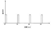
- FIG. 6 is an example of a graph showing the relationship between time and the discharge amount of the standard sample into the ionization chamber.
- the standard sample is introduced into the ion introduction port in the first time zone, the measurement sample is introduced in the next second time zone, and the standard sample is introduced in the next third time zone. Become.
- the mass spectrometer of the present invention it is possible to appropriately control the introduction timing of the standard sample while preventing the mixture of the measurement sample and the standard sample. In addition, even when a plurality of types of measurement samples are successively introduced into the ionization chamber in a short time, it is possible to obtain an accurate mass spectrum of each measurement sample.
- the standard sample channel may be arranged so that the standard sample is sprayed between the spray port of the measurement sample channel and the ion introduction port.
- the standard sample sprayed into the ionization chamber blows away the measurement sample toward the ion introduction port, so that only the standard sample is introduced into the ion introduction port.
- the concentration of the standard sample introduced into the ion introduction port can be adjusted by controlling the pulse valve to change the introduction amount. Therefore, the trouble of adjusting the concentration of the standard sample can be saved.
- the said standard sample flow path is the same flow path as the dry gas flow path for spraying dry gas, or the same flow path as the nebulization gas flow path for spraying nebulization gas. You may be allowed to. According to the mass spectrometer of the present invention, it is not necessary to newly form a standard sample channel. Further, when the standard sample is introduced into the standard sample flow path, the concentration of the standard sample introduced into the ion introduction port can be adjusted by controlling the pulse valve to change the introduction amount. Therefore, the trouble of adjusting the concentration of the standard sample can be saved.
- the standard sample flow path is the same flow path as the measurement sample flow path.
- the liquid standard sample is introduced by a pulse valve
- a gas standard sample may be introduced by a pulse valve.
- the measurement sample and the standard sample can be alternately arranged in the flow path. At this time, a plurality of LC units or GC units may be connected.
- a pulse valve for intermittently introducing a mobile phase is disposed in the standard sample flow path, and when the measurement sample is a liquid, the liquid mobile phase is introduced by the pulse valve, On the other hand, when the measurement sample is a gas, a gas mobile phase may be introduced by a pulse valve.
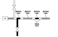
- the mobile phase can be injected between the measurement sample and the standard sample in the flow channel so that the measurement sample and the standard sample are not mixed in the flow channel.
- An example of the flow path when such a mobile phase is injected is shown in FIG.
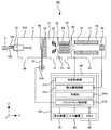
- FIG. 1 is a schematic configuration diagram illustrating an example of a liquid chromatograph mass spectrometer using the ESI method according to the first embodiment.
- the liquid chromatograph mass spectrometer 1 includes an LC unit 2, a probe (measurement sample ion source) 15, a probe (standard sample ion source) 215, a pulse valve 216, and a chamber (housing) 110.
- a chamber 11 a first intermediate chamber 12 adjacent to the ionization chamber 11, a second intermediate chamber 13 adjacent to the first intermediate chamber 12, a mass spectrometry chamber (MS section) 14 adjacent to the second intermediate chamber 13, And a computer 40 that controls the entire liquid chromatograph mass spectrometer 1.
- the ionization chamber 11 includes a rectangular parallelepiped chamber 110 of 13 cm ⁇ 13 cm ⁇ 12 cm, and the chamber 110 has an upper surface, a partition wall (rear surface), a front surface, a right side surface, a left side surface, and a lower surface.
- the inner space of the ionization chamber 11 is formed by being surrounded by the upper surface, the partition wall, the front surface, the right side surface, the left side surface, and the lower surface.
- a circular opening communicating with the front-rear direction (X direction) is formed on the front surface, and the probe 15 can be attached to the opening.
- a circular opening that communicates in the vertical direction (Z direction) is formed on the lower surface, and the probe 215 is attached to the opening.
- the probe 215 has the same shape as the probe 15 shown in FIG. 5 and has a double tube structure, and the standard sample supplied via the standard sample channel 255 is ejected from the inside of the circular tube.
- nitrogen gas supplied from the nebulization gas channel 256 is injected from between the circular tube and the circular tube-shaped nozzle.
- the ejected standard sample is sprayed in a mist state by the collision action with the nebulizing gas sprayed around the circular tube.
- ionization is performed by applying a high voltage of several kV from the wiring connected to the voltage source to the tip of the nozzle.
- the standard sample it is convenient for the standard sample to have a peak of fragment ions regularly.
- a low molecular weight standard sample such as PFTBA (Perfluorotributylamine) is used in a low mass-to-charge ratio (m / z) region.
- high molecular weight standards such as triazine (Tris- (perfluoroheptyl) -s-triazine) and PKF (Perfluorokerosene) A sample is used.
- the partition wall is arranged so as to partition the inside of the ionization chamber 11 and the inside of the first intermediate chamber 12, and the partition wall has a circular tube shape (diameter outer diameter 1.6 mm, inner diameter 0.5 mm) desolvation tube (ion introduction) Mouth) 19 is formed, and a dry gas flow path 50 is formed so as to cover the periphery of the desolvation tube 19.
- the desolvation tube 19 has a function of promoting desolvation and ionization by heating action or collision action when ions sprayed by the probe 15 or the probe 215 or fine sample droplets pass through the inside. Have. Further, when the desolvation tube 19 gets wet with the measurement sample or the standard sample, it is dried with a dry gas.
- the jet port of the probe 15 is directed forward (X direction) so as to face the entrance of the desolvation tube 19 with a predetermined distance (for example, 2 cm).
- the jet port of the probe 215 is directed upward (Z direction) so that the standard sample is sprayed at a predetermined flow rate (for example, 0.1 ml / min) between the jet port of the probe 15 and the inlet of the desolvation tube 19. It has been.
- a predetermined flow rate for example, 0.1 ml / min
- Examples of the pulse valve 216 include those manufactured by Musashi Engineering Co., Ltd., and are arranged in the standard sample channel 255.
- the pulse valve 216 is in an “open state” in which the standard sample is introduced into the standard sample channel 255 or a “closed state” in which the standard sample is not introduced, according to a control signal from the computer 40. It has become.
- the computer 40 includes a CPU 41, a display device 42, an input device 43, and a memory 44. Further, the functions processed by the CPU 41 will be described in the form of blocks.
- An analysis control unit 41a that controls the quadrupoles 16, 17 and the like by an operator's input operation and a detector control unit 41b that acquires an intensity signal from the detector 18.
- a creation unit 41c that creates a mass spectrum and stores it in the memory 44, and a pulse valve control unit 41d that controls the pulse valve 216 by an input operation of the measurer.
- the pulse valve control unit 41 d controls the pulse valve 216 based on an input signal from the input device 43. For example, when the time from the measurement start time t 1 to the measurement end time t 2 is 31 minutes and an input signal for “open state” is input every 9 minutes for 1 minute, t 1 to (t 1 +1 minutes) ), (T 1 +10 minutes) to (t 1 +11 minutes), (t 1 +20 minutes) to (t 1 +21 minutes), and (t 1 +30 minutes) to (t 1 +31 minutes).
- a pulse signal (control signal) for introducing a predetermined amount of the standard sample is output to the pulse valve 216 (see FIG. 6). Note that the condition content of the pulse signal can be changed by an input operation by the measurer, and the operation timing (introduction timing) and the introduction time (introduction amount) can be freely set.
- the creation unit 41 c performs control to create a mass spectrum and store it in the memory 44 based on the intensity signal acquired by the detector control unit 41 b.
- the mass spectrum of the measurement sample and the mass spectrum of the standard sample are separately stored in the memory 44 in synchronization with the operation timing of the pulse valve 216 based on the input signal input to the pulse valve control unit 41d.
- the measurement value (mass-to-charge ratio (m / z) and intensity value) of each peak obtained by measurement of the measurement sample is determined using the peak obtained by measurement of the standard sample.
- the mass spectrum of the sample the one having the closest time at which the mass spectrum of the measurement sample was obtained is selected.
- the mass spectrum of the standard sample obtained from t 1 to (t 1 +1 min) is used as the mass spectrum of the measurement sample obtained from (t 1 +1 min) to (t 1 +5 min).
- the mass spectra of the measurement samples obtained from (t 1 +5 minutes) to (t 1 +10 minutes) and (t 1 +11 minutes) to (t 1 +15 minutes) include (t 1 +10 minutes) to (t 1 +11).
- the mass spectrum of the standard sample obtained in (min) is used, and the measurement samples obtained from (t 1 +15 min) to (t 1 +20 min) and (t 1 +21 min) to (t 1 +25 min) are used.
- the mass spectrum of the standard sample obtained from (t 1 +20 minutes) to (t 1 +21 minutes) is used, and the measurement sample obtained from (t 1 +25 minutes) to (t 1 +30 minutes) Is obtained from (t 1 +30 minutes) to (t 1 +31 minutes).
- the mass spectrum of the prepared standard sample is used. Thereby, even when a plurality of types of measurement samples are successively introduced into the ionization chamber 11 in a short time, an accurate mass spectrum of each measurement sample can be acquired.
- the introduction timing of the standard sample can be appropriately controlled while preventing the measurement sample and the standard sample from being mixed. Further, when the standard sample is introduced into the standard sample channel 255, the concentration of the standard sample introduced into the desolvation tube 19 can be adjusted by controlling the pulse valve 216 to change the introduction amount.
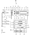
- FIG. 2 is a schematic configuration diagram illustrating an example of a liquid chromatograph mass spectrometer using the ESI method according to the second embodiment.
- the liquid chromatograph mass spectrometer 301 includes an LC unit 2, a probe (measurement sample ion source) 15, a pulse valve 216, an ionization chamber 11 including a chamber (housing) 210, and an ionization chamber 11 adjacent to the ionization chamber 11.
- the pulse valve 216 is disposed in the dry gas channel (standard sample channel) 51.
- the pulse valve 216 receives either a control signal from the computer 340, so that either the “open state” in which the standard sample is introduced into the dry gas flow path 51 or the “closed state” in which the standard sample is not introduced. It comes to be in a state.
- the computer 340 includes a CPU 341, a display device 42, an input device 43, and a memory 44. Further, the functions processed by the CPU 341 will be described in blocks.
- An analysis control unit 41a that controls the quadrupoles 16, 17 and the like by an operator's input operation, and a detector control unit 41b that acquires an intensity signal from the detector 18.
- a creation unit 341c that creates a mass spectrum and stores it in the memory 44, and a pulse valve control unit 41d that controls the pulse valve 216 by an input operation of the measurer.
- the creation unit 341c performs control for creating a mass spectrum and storing it in the memory 44 based on the intensity signal acquired by the detector control unit 41b. Then, the mass-to-charge ratio (m / z) of each peak obtained by measurement of the measurement sample is determined using the peak obtained by measurement of the standard sample. Two samples that exist before and after the time when the mass spectrum of the measurement sample is obtained are used so as to sandwich the time when the mass spectrum of the sample is obtained.
- the liquid chromatograph mass spectrometer 301 of the second embodiment it is possible to appropriately control the introduction timing of the standard sample while preventing the mixture of the measurement sample and the standard sample. Further, when the standard sample is introduced into the dry gas channel 51, the concentration of the standard sample introduced into the desolvation tube 19 can be adjusted by controlling the pulse valve 216 to change the introduction amount.
- FIG. 3 is a schematic configuration diagram illustrating an example of a liquid chromatograph mass spectrometer using the ESI method according to the third embodiment.
- the liquid chromatograph mass spectrometer 401 includes an LC unit 2, a probe (measurement sample ion source) 15, a pulse valve 216, a pulse valve 416, an ionization chamber 11 including a chamber (housing) 210, and an ionization chamber. 11, a second intermediate chamber 13 adjacent to the first intermediate chamber 12, a mass analysis chamber (MS section) 14 adjacent to the second intermediate chamber 13, and a liquid chromatograph mass spectrometer And a computer 440 that controls the entire system 401.
- LC unit 2 includes an LC unit 2, a probe (measurement sample ion source) 15, a pulse valve 216, a pulse valve 416, an ionization chamber 11 including a chamber (housing) 210, and an ionization chamber. 11, a second intermediate chamber 13 adjacent to the first intermediate chamber 12, a mass analysis chamber (
- the pulse valve 216 is disposed in the measurement sample channel (standard sample channel) 155. Then, when the control signal is input from the computer 440, the pulse valve 216 is in an “open state” in which a predetermined amount of the standard sample is introduced into the measurement sample channel 155 or in a “closed state” in which the standard sample is not introduced. It will be in any state of. Further, the pulse valve 416 is disposed in the measurement sample channel 155 and is disposed in the measurement sample channel 155 in front of the pulse valve 216.
- the pulse valve 416 is in an “open state” in which a predetermined amount of gas (mobile phase) is introduced into the measurement sample channel 155 or a gas (mobile phase) is introduced into the measurement sample flow channel 155 by receiving a control signal from the computer 440. It will be in any of the "closed state”. Thus, gas (mobile phase) can be injected between the measurement sample and the standard sample in the measurement sample channel 155 so that the measurement sample and the standard sample are not mixed in the measurement sample channel 155 (FIG. 7).
- the computer 440 includes a CPU 441, a display device 42, an input device 43, and a memory 44. Further, the function processed by the CPU 441 will be described as a block.
- An analysis control unit 41a that controls the quadrupoles 16, 17 and the like by an input operation of a measurer, and a detector control unit 41b that acquires an intensity signal from the detector 18.
- a creation unit 41c that creates a mass spectrum and stores it in the memory 44
- a pulse valve control unit 441d that controls the pulse valve 216 and the pulse valve 416 by an input operation of the measurer.
- liquid chromatograph mass spectrometer 401 of the third embodiment it is possible to appropriately control the introduction timing of the standard sample while preventing the mixture of the measurement sample and the standard sample.
- a gas mobile phase
- LC units are connected to the measurement sample channel 155. Also good.
- the pulse valve 216 is configured to be disposed in the dry gas flow channel 51, but is disposed in the nebulization gas flow channel 156. It is good also as a structure.
- the mass spectrometer of the present invention is used, for example, as a calibration method for a mass analyzer in a chromatograph mass spectrometer.
Landscapes
- Chemical & Material Sciences (AREA)
- Analytical Chemistry (AREA)
- Physics & Mathematics (AREA)
- Engineering & Computer Science (AREA)
- Plasma & Fusion (AREA)
- Dispersion Chemistry (AREA)
- Health & Medical Sciences (AREA)
- Life Sciences & Earth Sciences (AREA)
- Biochemistry (AREA)
- General Health & Medical Sciences (AREA)
- General Physics & Mathematics (AREA)
- Immunology (AREA)
- Pathology (AREA)
- Other Investigation Or Analysis Of Materials By Electrical Means (AREA)
Abstract
Description
液体クロマトグラフ質量分析装置201は、LC部2と、プローブ(イオン源)15と、チャンバ(筐体)210を備えるイオン化室11と、イオン化室11に隣接する第1中間室12と、第1中間室12に隣接する第2中間室13と、第2中間室13に隣接する質量分析室(MS部)14と、液体クロマトグラフ質量分析装置201全体の制御を行うコンピュータ240とを備える。
ここで、図5(a)は、プローブの側面図であり、図5(b)は、図5(a)に示すAの拡大断面図である。プローブ15は、二重管構造になっており、測定試料流路155を介して供給された測定試料は円管151の内側から噴出される。一方、ネブライズガス流路156から供給された窒素ガスは円管151と円管形状のノズル152との間から噴射される。これにより、噴出された測定試料は、円管151の周囲に噴射されるネブライズガスとの衝突作用により霧状態となって噴霧される。
また、図示は省略するが、ノズル152の先端には電圧源から数kVの高電圧が印加されるように配線が接続されており、このような構成によりイオン化が行われるようになっている。
前面には、前後方向(X方向)に連通する円形状の開口部が形成されており、開口部にプローブ15が取り付けられるようになっている。
なお、下面には、ドレイン30が形成されており、不要な試料はドレイン30から外部へ排出されるようになっている。
第2中間室13の内部には、オクタポール23と、フォーカスレンズ24とが設けられ、第2中間室13の下面には、ターボ分子ポンプ(TMP)で真空排気するための排気口32が設けられている。また、第2中間室13と質量分析室14との間の隔壁には、細孔を有する入口レンズ25が設けられ、この細孔を介して第2中間室13の内部と質量分析室14の内部とが連通する。
なお、イオンレンズ21と、オクタポール23と、フォーカスレンズ24と、入口レンズ25とは、それぞれの真空状態下で、それぞれのイオン速度下のもとで通過するイオンを効率的に次段に送り出すための収束作用を有する。
よって、測定試料と標準試料とを「ほぼ同時」かつ「別々」に質量分析を行う方法が開示されている。例えば、測定試料流路155中に時間的に分離して標準試料を導入する方法(例えば、特許文献2参照)や、複数のイオン用デバイスを用意して導入方向を機械的に切り替える方法(例えば、特許文献3参照)や、標準試料を測定試料流路155と異なる別の流路から真空中に導入する方法等がある。
本発明の質量分析装置によれば、イオン化室の内部に噴霧された標準試料が、イオン導入口に向かう測定試料を吹き飛ばすことで、標準試料のみがイオン導入口に導入される。また、標準試料を標準試料流路中に導入する際に、パルスバルブを制御して導入量を変化させることにより、イオン導入口に導入される標準試料の濃度も調整可能となる。よって、標準試料の濃度を調整する手間を省くことができる。
本発明の質量分析装置によれば、標準試料流路を新たに形成する必要がなくなる。また、標準試料を標準試料流路中に導入する際に、パルスバルブを制御して導入量を変化させることにより、イオン導入口に導入される標準試料の濃度も調整可能となる。よって、標準試料の濃度を調整する手間を省くことができる。
本発明の質量分析装置によれば、流路中において測定試料と標準試料とが交互にならぶようにすることができる。このとき、複数のLC部やGC部が連結されるようにしてもよい。
さらに、上記発明において、前記標準試料流路中に、間欠的に移動相を導入するパルスバルブが配置されており、前記測定試料が液体であるときには、液体の移動相がパルスバルブによって導入され、一方、前記測定試料が気体であるときには、気体の移動相がパルスバルブによって導入されるようにしてもよい。
本発明の質量分析装置によれば、流路中で測定試料と標準試料とが混在しないよう、流路中において測定試料と標準試料との間に移動相を注入することができる。このような移動相を注入した際の流路の一例を図7に示す。
図1は、実施形態1に係るESI法を用いた液体クロマトグラフ質量分析装置の一例を示す概略構成図である。なお、上述した従来の液体クロマトグラフ質量分析装置201と同様のものについては、同じ符号を付している。
液体クロマトグラフ質量分析装置1は、LC部2と、プローブ(測定試料用イオン源)15と、プローブ(標準試料用イオン源)215と、パルスバルブ216と、チャンバ(筐体)110を備えるイオン化室11と、イオン化室11に隣接する第1中間室12と、第1中間室12に隣接する第2中間室13と、第2中間室13に隣接する質量分析室(MS部)14と、液体クロマトグラフ質量分析装置1全体の制御を行うコンピュータ40とを備える。
前面には、前後方向(X方向)に連通する円形状の開口部が形成されており、この開口部にプローブ15が取り付けられるようになっている。
プローブ215は、図5に示したプローブ15と同様の形状であって二重管構造になっており、標準試料流路255を介して供給される標準試料は円管の内側から噴出される。一方、ネブライズガス流路256から供給される窒素ガスは円管と円管形状のノズルとの間から噴射される。これにより、噴出された標準試料は、円管の周囲に噴射されるネブライズガスとの衝突作用により霧状態となって噴霧される。
また、電圧源に接続された配線から数kVの高電圧がノズルの先端に印加されることでイオン化が行われるようになっている。
なお、下面には、ドレイン30が形成されており、不要な試料はドレイン30から外部へ排出されるようになっている。
図2は、実施形態2に係るESI法を用いた液体クロマトグラフ質量分析装置の一例を示す概略構成図である。なお、上述した液体クロマトグラフ質量分析装置1、201と同様のものについては、同じ符号を付している。
液体クロマトグラフ質量分析装置301は、LC部2と、プローブ(測定試料用イオン源)15と、パルスバルブ216と、チャンバ(筐体)210を備えるイオン化室11と、イオン化室11に隣接する第1中間室12と、第1中間室12に隣接する第2中間室13と、第2中間室13に隣接する質量分析室(MS部)14と、液体クロマトグラフ質量分析装置301全体の制御を行うコンピュータ340とを備える。
図3は、実施形態3に係るESI法を用いた液体クロマトグラフ質量分析装置の一例を示す概略構成図である。なお、上述した液体クロマトグラフ質量分析装置1と同様のものについては、同じ符号を付している。
液体クロマトグラフ質量分析装置401は、LC部2と、プローブ(測定試料用イオン源)15と、パルスバルブ216と、パルスバルブ416と、チャンバ(筐体)210を備えるイオン化室11と、イオン化室11に隣接する第1中間室12と、第1中間室12に隣接する第2中間室13と、第2中間室13に隣接する質量分析室(MS部)14と、液体クロマトグラフ質量分析装置401全体の制御を行うコンピュータ440とを備える。
また、パルスバルブ416は、測定試料流路155中に配置され、測定試料流路155中においてパルスバルブ216より前段に配置されている。そして、パルスバルブ416は、コンピュータ440から制御信号が入力されることで、測定試料流路155中に所定量の気体(移動相)を導入する「開状態」か、気体(移動相)を導入しない「閉状態」かのいずれの状態となるようになっている。
これにより、測定試料流路155中で測定試料と標準試料とが混在しないよう、測定試料流路155中において測定試料と標準試料との間に気体(移動相)を注入することができる(図7参照)。
(1)上述した液体クロマトグラフ質量分析装置301では、パルスバルブ216は、乾燥ガス流路51中に配置されているような構成を示したが、ネブライズガス流路156中に配置されているような構成としてもよい。
11 イオン化室
14 質量分析室(質量分析部)
15 プローブ
19 脱溶媒管(イオン導入口)
110 チャンバ(筐体)
155 測定試料流路
216 パルスバルブ
255 標準試料流路
Claims (5)
- 試料をイオン化するイオン化室と、当該イオン化室からイオンが導入される質量分析部とを備え、
前記イオン化室は、筐体を備え、当該筐体によって内部空間が形成され、
前記筐体には、前記イオン化室の内部に測定試料を噴霧するための測定試料流路を有するプローブが取り付けられるとともに、前記イオン化室の内部と質量分析部の内部とを連通するイオン導入口が形成されており、
標準試料を測定することにより得られたマススペクトルの測定値を用いて、前記測定試料を測定することにより得られたマススペクトルの測定値を校正する質量分析装置であって、
前記イオン化室の内部に標準試料を噴霧するための標準試料流路と、当該標準試料流路中に配置され、間欠的に標準試料を導入するパルスバルブとを備えることを特徴とする質量分析装置。 - 前記測定試料流路の噴霧口と前記イオン導入口との間に前記標準試料を噴霧するように、前記標準試料流路が配置されていることを特徴とする請求項1に記載の質量分析装置。
- 前記標準試料流路は、乾燥ガスを噴霧するための乾燥ガス流路と同一流路となっているか、或いは、ネブライズガスを噴霧するためのネブライズガス流路と同一流路となっていることを特徴とする請求項1に記載の質量分析装置。
- 前記標準試料流路は、前記測定試料流路と同一流路となっており、
前記測定試料が液体であるときには、液体の標準試料がパルスバルブによって導入され、一方、前記測定試料が気体であるときには、気体の標準試料がパルスバルブによって導入されることを特徴とする請求項1に記載の質量分析装置。 - 前記標準試料流路中に、間欠的に移動相を導入するパルスバルブが配置されており、
前記測定試料が液体であるときには、液体の移動相がパルスバルブによって導入され、一方、前記測定試料が気体であるときには、気体の移動相がパルスバルブによって導入されることを特徴とする請求項4に記載の質量分析装置。
Priority Applications (5)
| Application Number | Priority Date | Filing Date | Title |
|---|---|---|---|
| JP2016530762A JP6179671B2 (ja) | 2014-07-03 | 2014-07-03 | 質量分析装置 |
| US15/117,868 US9741548B2 (en) | 2014-07-03 | 2014-07-03 | Mass spectrometer |
| EP14896695.5A EP3166129A4 (en) | 2014-07-03 | 2014-07-03 | Mass spectrometer |
| CN201480078992.8A CN106463335B (zh) | 2014-07-03 | 2014-07-03 | 质谱分析装置 |
| PCT/JP2014/067791 WO2016002045A1 (ja) | 2014-07-03 | 2014-07-03 | 質量分析装置 |
Applications Claiming Priority (1)
| Application Number | Priority Date | Filing Date | Title |
|---|---|---|---|
| PCT/JP2014/067791 WO2016002045A1 (ja) | 2014-07-03 | 2014-07-03 | 質量分析装置 |
Publications (1)
| Publication Number | Publication Date |
|---|---|
| WO2016002045A1 true WO2016002045A1 (ja) | 2016-01-07 |
Family
ID=55018644
Family Applications (1)
| Application Number | Title | Priority Date | Filing Date |
|---|---|---|---|
| PCT/JP2014/067791 Ceased WO2016002045A1 (ja) | 2014-07-03 | 2014-07-03 | 質量分析装置 |
Country Status (5)
| Country | Link |
|---|---|
| US (1) | US9741548B2 (ja) |
| EP (1) | EP3166129A4 (ja) |
| JP (1) | JP6179671B2 (ja) |
| CN (1) | CN106463335B (ja) |
| WO (1) | WO2016002045A1 (ja) |
Cited By (4)
| Publication number | Priority date | Publication date | Assignee | Title |
|---|---|---|---|---|
| WO2017094178A1 (ja) * | 2015-12-04 | 2017-06-08 | 株式会社島津製作所 | 液体試料分析システム |
| JPWO2018100612A1 (ja) * | 2016-11-29 | 2019-04-04 | 株式会社島津製作所 | イオン化装置及び質量分析装置 |
| WO2020240640A1 (ja) * | 2019-05-27 | 2020-12-03 | 株式会社島津製作所 | 質量分析装置 |
| JP2023117896A (ja) * | 2022-02-14 | 2023-08-24 | 株式会社島津製作所 | イオン分析装置 |
Families Citing this family (13)
| Publication number | Priority date | Publication date | Assignee | Title |
|---|---|---|---|---|
| KR101828117B1 (ko) | 2010-10-14 | 2018-02-09 | 셀라니즈 세일즈 저머니 게엠베하 | 커플링된 유리-섬유 강화된 폴리옥시메틸렌 |
| CN105223264B (zh) * | 2015-09-21 | 2017-12-29 | 广东联捷生物科技有限公司 | 一种质谱定量分析的模拟内标方法、装置及应用 |
| CN117304644A (zh) | 2015-09-30 | 2023-12-29 | 塞拉尼斯销售德国有限公司 | 低摩擦无刺耳音的组合件 |
| CN110741045A (zh) | 2017-06-16 | 2020-01-31 | 塞拉尼斯销售德国有限公司 | 具有低排放的增强的聚甲醛组合物 |
| GB201808949D0 (en) | 2018-05-31 | 2018-07-18 | Micromass Ltd | Bench-top time of flight mass spectrometer |
| US11367607B2 (en) | 2018-05-31 | 2022-06-21 | Micromass Uk Limited | Mass spectrometer |
| GB201808912D0 (en) | 2018-05-31 | 2018-07-18 | Micromass Ltd | Bench-top time of flight mass spectrometer |
| GB201808932D0 (en) | 2018-05-31 | 2018-07-18 | Micromass Ltd | Bench-top time of flight mass spectrometer |
| GB201808893D0 (en) * | 2018-05-31 | 2018-07-18 | Micromass Ltd | Bench-top time of flight mass spectrometer |
| GB201808894D0 (en) | 2018-05-31 | 2018-07-18 | Micromass Ltd | Mass spectrometer |
| CN109326499B (zh) * | 2018-09-29 | 2020-06-02 | 清华大学深圳研究生院 | 一种用于去除质谱仪进样结晶的装置 |
| CN113383232B (zh) * | 2019-02-04 | 2023-09-19 | 株式会社日立高新技术 | 液相色谱质量分析装置 |
| TWI687630B (zh) * | 2019-04-16 | 2020-03-11 | 亞台富士精機股份有限公司 | 乾燥系統與控制方法 |
Citations (4)
| Publication number | Priority date | Publication date | Assignee | Title |
|---|---|---|---|---|
| JP2000243344A (ja) * | 1999-02-18 | 2000-09-08 | Japan Science & Technology Corp | アイソトポマー質量分析装置 |
| JP2009031201A (ja) * | 2007-07-30 | 2009-02-12 | Hitachi High-Technologies Corp | 液体クロマトグラフ/質量分析計 |
| JP2012163570A (ja) * | 2006-03-31 | 2012-08-30 | Thermo Fisher Scientific (Bremen) Gmbh | ガスを分析装置に供給する装置 |
| JP2013521470A (ja) * | 2010-02-26 | 2013-06-10 | ゾイクス コーポレーション | 飛行時間型質量分析法におけるパルス化質量校正 |
Family Cites Families (10)
| Publication number | Priority date | Publication date | Assignee | Title |
|---|---|---|---|---|
| JPH10132786A (ja) | 1996-10-30 | 1998-05-22 | Shimadzu Corp | 質量分析装置 |
| US6410915B1 (en) | 1998-06-18 | 2002-06-25 | Micromass Limited | Multi-inlet mass spectrometer for analysis of liquid samples by electrospray or atmospheric pressure ionization |
| JP2002245962A (ja) * | 2000-12-12 | 2002-08-30 | Jeol Ltd | エレクトロスプレー・イオン源 |
| US6657191B2 (en) * | 2001-03-02 | 2003-12-02 | Bruker Daltonics Inc. | Means and method for multiplexing sprays in an electrospray ionization source |
| JP2006073437A (ja) * | 2004-09-03 | 2006-03-16 | Idx Technologies Corp | 光蓄積型レーザーイオン化質量分析装置 |
| US20060255261A1 (en) * | 2005-04-04 | 2006-11-16 | Craig Whitehouse | Atmospheric pressure ion source for mass spectrometry |
| US8803080B2 (en) * | 2007-06-02 | 2014-08-12 | Cerno Bioscience Llc | Self calibration approach for mass spectrometry |
| JP4985153B2 (ja) * | 2007-07-03 | 2012-07-25 | 株式会社島津製作所 | クロマトグラフ質量分析装置 |
| JP5316481B2 (ja) * | 2010-06-11 | 2013-10-16 | 株式会社島津製作所 | 質量分析装置 |
| JP5675442B2 (ja) * | 2011-03-04 | 2015-02-25 | 株式会社日立ハイテクノロジーズ | 質量分析方法及び質量分析装置 |
-
2014
- 2014-07-03 EP EP14896695.5A patent/EP3166129A4/en not_active Withdrawn
- 2014-07-03 US US15/117,868 patent/US9741548B2/en active Active
- 2014-07-03 CN CN201480078992.8A patent/CN106463335B/zh not_active Expired - Fee Related
- 2014-07-03 WO PCT/JP2014/067791 patent/WO2016002045A1/ja not_active Ceased
- 2014-07-03 JP JP2016530762A patent/JP6179671B2/ja active Active
Patent Citations (4)
| Publication number | Priority date | Publication date | Assignee | Title |
|---|---|---|---|---|
| JP2000243344A (ja) * | 1999-02-18 | 2000-09-08 | Japan Science & Technology Corp | アイソトポマー質量分析装置 |
| JP2012163570A (ja) * | 2006-03-31 | 2012-08-30 | Thermo Fisher Scientific (Bremen) Gmbh | ガスを分析装置に供給する装置 |
| JP2009031201A (ja) * | 2007-07-30 | 2009-02-12 | Hitachi High-Technologies Corp | 液体クロマトグラフ/質量分析計 |
| JP2013521470A (ja) * | 2010-02-26 | 2013-06-10 | ゾイクス コーポレーション | 飛行時間型質量分析法におけるパルス化質量校正 |
Non-Patent Citations (1)
| Title |
|---|
| See also references of EP3166129A4 * |
Cited By (8)
| Publication number | Priority date | Publication date | Assignee | Title |
|---|---|---|---|---|
| WO2017094178A1 (ja) * | 2015-12-04 | 2017-06-08 | 株式会社島津製作所 | 液体試料分析システム |
| JPWO2017094178A1 (ja) * | 2015-12-04 | 2018-05-17 | 株式会社島津製作所 | 液体試料分析システム |
| JPWO2018100612A1 (ja) * | 2016-11-29 | 2019-04-04 | 株式会社島津製作所 | イオン化装置及び質量分析装置 |
| WO2020240640A1 (ja) * | 2019-05-27 | 2020-12-03 | 株式会社島津製作所 | 質量分析装置 |
| JPWO2020240640A1 (ja) * | 2019-05-27 | 2021-12-23 | 株式会社島津製作所 | 質量分析装置 |
| JP7140282B2 (ja) | 2019-05-27 | 2022-09-21 | 株式会社島津製作所 | 質量分析装置 |
| JP2023117896A (ja) * | 2022-02-14 | 2023-08-24 | 株式会社島津製作所 | イオン分析装置 |
| JP7746875B2 (ja) | 2022-02-14 | 2025-10-01 | 株式会社島津製作所 | イオン分析装置 |
Also Published As
| Publication number | Publication date |
|---|---|
| EP3166129A1 (en) | 2017-05-10 |
| EP3166129A4 (en) | 2018-06-13 |
| CN106463335A (zh) | 2017-02-22 |
| CN106463335B (zh) | 2019-02-19 |
| JP6179671B2 (ja) | 2017-08-16 |
| US9741548B2 (en) | 2017-08-22 |
| US20170011897A1 (en) | 2017-01-12 |
| JPWO2016002045A1 (ja) | 2017-04-27 |
Similar Documents
| Publication | Publication Date | Title |
|---|---|---|
| JP6179671B2 (ja) | 質量分析装置 | |
| US12080537B2 (en) | IRMS sample introduction system and method | |
| CN102971826B (zh) | 大气压电离质谱仪 | |
| EP3577677B1 (en) | Fourier transform mass spectrometer | |
| JP3791479B2 (ja) | イオンガイド | |
| JP6620896B2 (ja) | イオン化装置及び質量分析装置 | |
| GB2563194A (en) | Dual mode ionization device | |
| EP3033763A1 (en) | Sample quantitation with a miniature mass spectrometer | |
| US7230237B2 (en) | Mass spectrometer | |
| EP4091191A1 (en) | High pressure mass analyzer | |
| EP1829080A2 (en) | Atmospheric pressure ionization with optimized drying gas flow | |
| JP2002107344A (ja) | 液体クロマトグラフ質量分析装置 | |
| EP2715774A2 (en) | Ion inlet for a mass spectrometer | |
| WO2018100621A1 (ja) | イオン化装置及び質量分析装置 | |
| JP4811361B2 (ja) | 大気圧化学イオン化質量分析装置 |
Legal Events
| Date | Code | Title | Description |
|---|---|---|---|
| 121 | Ep: the epo has been informed by wipo that ep was designated in this application |
Ref document number: 14896695 Country of ref document: EP Kind code of ref document: A1 |
|
| ENP | Entry into the national phase |
Ref document number: 2016530762 Country of ref document: JP Kind code of ref document: A |
|
| REEP | Request for entry into the european phase |
Ref document number: 2014896695 Country of ref document: EP |
|
| WWE | Wipo information: entry into national phase |
Ref document number: 2014896695 Country of ref document: EP |
|
| WWE | Wipo information: entry into national phase |
Ref document number: 15117868 Country of ref document: US |
|
| NENP | Non-entry into the national phase |
Ref country code: DE |