WO2016002085A1 - テープフィーダ - Google Patents
テープフィーダ Download PDFInfo
- Publication number
- WO2016002085A1 WO2016002085A1 PCT/JP2014/067979 JP2014067979W WO2016002085A1 WO 2016002085 A1 WO2016002085 A1 WO 2016002085A1 JP 2014067979 W JP2014067979 W JP 2014067979W WO 2016002085 A1 WO2016002085 A1 WO 2016002085A1
- Authority
- WO
- WIPO (PCT)
- Prior art keywords
- reel
- tape
- feeder
- reel holding
- pair
- Prior art date
- Legal status (The legal status is an assumption and is not a legal conclusion. Google has not performed a legal analysis and makes no representation as to the accuracy of the status listed.)
- Ceased
Links
Images


Classifications
-
- H—ELECTRICITY
- H05—ELECTRIC TECHNIQUES NOT OTHERWISE PROVIDED FOR
- H05K—PRINTED CIRCUITS; CASINGS OR CONSTRUCTIONAL DETAILS OF ELECTRIC APPARATUS; MANUFACTURE OF ASSEMBLAGES OF ELECTRICAL COMPONENTS
- H05K13/00—Apparatus or processes specially adapted for manufacturing or adjusting assemblages of electric components
- H05K13/02—Feeding of components
-
- H—ELECTRICITY
- H05—ELECTRIC TECHNIQUES NOT OTHERWISE PROVIDED FOR
- H05K—PRINTED CIRCUITS; CASINGS OR CONSTRUCTIONAL DETAILS OF ELECTRIC APPARATUS; MANUFACTURE OF ASSEMBLAGES OF ELECTRICAL COMPONENTS
- H05K13/00—Apparatus or processes specially adapted for manufacturing or adjusting assemblages of electric components
- H05K13/04—Mounting of components, e.g. of leadless components
- H05K13/0417—Feeding with belts or tapes
-
- B—PERFORMING OPERATIONS; TRANSPORTING
- B65—CONVEYING; PACKING; STORING; HANDLING THIN OR FILAMENTARY MATERIAL
- B65H—HANDLING THIN OR FILAMENTARY MATERIAL, e.g. SHEETS, WEBS, CABLES
- B65H19/00—Changing the web roll
- B65H19/10—Changing the web roll in unwinding mechanisms or in connection with unwinding operations
- B65H19/12—Lifting, transporting, or inserting the web roll; Removing empty core
-
- H—ELECTRICITY
- H05—ELECTRIC TECHNIQUES NOT OTHERWISE PROVIDED FOR
- H05K—PRINTED CIRCUITS; CASINGS OR CONSTRUCTIONAL DETAILS OF ELECTRIC APPARATUS; MANUFACTURE OF ASSEMBLAGES OF ELECTRICAL COMPONENTS
- H05K13/00—Apparatus or processes specially adapted for manufacturing or adjusting assemblages of electric components
- H05K13/04—Mounting of components, e.g. of leadless components
- H05K13/0417—Feeding with belts or tapes
- H05K13/0419—Feeding with belts or tapes tape feeders
Definitions
- the technology disclosed in this specification relates to a tape feeder that supplies electronic components to a substrate working machine.
- the tape feeder includes a reel holding unit that holds a reel on which a tape that holds an electronic component is wound, and a feeder main body that sends the tape from the reel to the substrate working machine.
- a plurality of tape feeders are mounted in parallel on the substrate working machine along the substrate transport direction.
- the reel holding part is wider than the feeder body. For this reason, the number of tape feeders that can be mounted on the substrate working machine is limited by the width of the reel holder.
- a tape feeder disclosed in Japanese Patent Application Laid-Open No. 2004-47951 includes a movable mechanism provided between a feeder main body and a reel holding portion.
- the movable mechanism allows the reel holder to move relative to the feeder body.
- the movable mechanism changes the position of the reel holding unit with respect to the feeder main body so as to avoid contact of the reel holding unit between adjacent tape feeders.
- the number of tape feeders that can be mounted on the substrate working machine is limited by the width of the narrow feeder body, not the width of the wide reel holder.
- the tape feeder is provided with a movable mechanism, more tape feeders can be mounted on the substrate working machine.
- the substrate working machine can realize mounting of various types of electronic components and high production efficiency.
- a space where such a tape feeder is mounted when observed by an operator, some reel holders are blocked by other reel holders, and workability for exchanging reels that have consumed tape deteriorates. .
- This specification aims at providing the technique which improves such deterioration of workability
- One embodiment of a tape feeder disclosed in the present specification is configured to supply electronic components to a substrate working machine, and includes a reel holder, a feeder body, and a movable mechanism.
- the reel holding unit holds the first reel on which the first tape holding the electronic component is wound and the second reel on which the second tape holding the electronic component is wound at different positions on the reel holding surface.
- the feeder main body sends the first tape from the first reel to the substrate working machine, and automatically feeds the second tape from the second reel to the substrate working machine after the first tape is consumed.
- the movable mechanism is provided between the feeder main body and the reel holding portion, and allows relative movement of the reel holding portion with respect to the feeder main body.
- the movable mechanism makes it possible to change the position of the reel holding portion with respect to the feeder main body between an upper position and a lower position.
- the movable mechanism further allows the position of the reel holding portion with respect to the feeder main body to be changed between an approach position and a separation position at least at a lower position.
- the movable mechanism of the above embodiment can change the position of the reel holding unit relative to the feeder body between the upper side position and the lower side position so as to avoid contact of the reel holding unit between adjacent tape feeders. As a result, more tape feeders can be mounted on the substrate working machine. Furthermore, the movable mechanism of the above embodiment can change the position of the reel holding unit disposed at the lower position relative to the feeder main body between the approach position and the separation position. Accordingly, when the reel holding portion arranged at the lower position is placed at the separation position, the reel holding portion is exposed from the reel holding portion arranged at the upper position, so that the reel held by the reel holding portion is Can be easily replaced.
- One embodiment of a tape feeder disclosed in the present specification is configured to supply electronic components to a substrate working machine, and may include a reel holding unit, a feeder body, and a movable mechanism.
- the reel holding unit holds the first reel on which the first tape holding the electronic component is wound and the second reel on which the second tape holding the electronic component is wound at different positions on the reel holding surface. May be.
- the electronic component held on the first reel and the electronic component held on the second reel may be of the same type or different types.
- the reel holding unit may hold three or more reels as necessary.
- the feeder main body may send the first tape from the first reel to the substrate working machine, and may automatically send the second tape from the second reel to the substrate working machine after the first tape is consumed. .
- the tape feeder can automatically perform the splicing work of the tape.
- the movable mechanism may be provided between the feeder main body and the reel holding portion, and may allow the reel holding portion to move relative to the feeder main body.
- the movable mechanism may change the position of the reel holding unit with respect to the feeder main body between an upper position and a lower position.
- the movable mechanism may further change the position of the reel holding portion with respect to the feeder main body between an approach position and a separation position at least at a lower position.
- the movable mechanism may have a guide arm including a guide portion that extends parallel to the reel holding surface.
- the reel holding part may be configured to be slidable between the approach position and the separation position along the guide part. According to this aspect, the operator can easily change the position of the reel holding portion with respect to the feeder main body between the approach position and the separation position at least in the lower position.
- the guide arm may be configured to be movable in parallel between a position when the reel holding unit is arranged at the upper position and a position when the reel holding unit is arranged at the lower position. According to this aspect, the operator can easily change the position of the reel holding portion with respect to the feeder main body between the upper position and the lower position.
- the movable mechanism may have a first attachment / detachment portion and a second attachment / detachment portion to / from which the guide arm is selectively attached / detached.
- the reel holding portion when the guide arm is attached to the first attaching / detaching portion, the reel holding portion is disposed at the upper position.
- the reel holding portion When the guide arm is attached to the second attaching / detaching portion, the reel holding portion is disposed at the lower position.
- the form of the movable mechanism is simplified, and the movable mechanism is resistant to breakage.
- the guide arm may be formed with an opening extending along the sliding direction of the reel holding portion as a guide portion.
- the opening may be formed with a pair of grooves including a lower groove formed on a lower edge defining the opening and an upper groove formed on an upper edge defining the opening.
- the reel holding part may have a pair of rollers inserted into the opening of the guide arm. The position of the reel holding portion with respect to the feeder body is fixed when one of the pair of rollers is fitted into the lower groove and the other is fitted into the upper groove. According to this aspect, positioning in the sliding direction of the reel holding part with respect to the feeder main body can be realized with a simple structure.
- the pair of grooves may be formed in each of one end and the other end of the opening of the guide arm.
- the reel holding portion When the pair of rollers are fitted into a pair of grooves formed at one end of the opening, the reel holding portion is disposed at the approach position.
- the pair of rollers When the pair of rollers are fitted into the pair of grooves formed at the other end of the opening, the reel holding portion is disposed at the separation position. According to this aspect, positioning of the approach position and the separation position of the reel holding portion with respect to the feeder main body can be realized with a simple structure.
- the reel holding part may have a first holding part and a second holding part.
- the first holding unit may be configured to hold the first reel.
- the second holding portion is disposed on a side farther from the feeder main body than the first holding portion, and is located between a normal position for holding the second reel and a storage position that approaches the feeder main body and does not hold the second reel. It may be configured to be movable. According to this aspect, when the second holding unit does not hold the second reel, the space can be saved by moving the second holding unit to the storage position.
- FIG. 1 shows an electronic component mounting machine 1 used in an electronic component mounting line.
- the electronic component mounting machine 1 is a device for mounting electronic components on a circuit board, and includes a transport device 2, a mounting head 3, and a moving device 4.
- the conveyance device 2 is a double conveyor type, and conveys the circuit board along the conveyance direction (arrow direction shown in the drawing).
- the mounting head 3 is connected to the moving device 4 and has a suction nozzle that sucks electronic components.
- the moving device 4 moves the mounting head 3 in a plane parallel to the surface of the circuit board to be conveyed.
- An electronic component supply device 5 is mounted on the electronic component mounting machine 1.
- the electronic component supply apparatus 5 includes a plurality of tape feeders 10 arranged in parallel along the conveyance direction of the circuit board. As described above, the electronic component mounting machine 1 sucks the electronic component supplied from the tape feeder 10 of the electronic component supply device 5 with the suction nozzle of the mounting head 3, and uses the moving device 4 to circuit the mounting head 3. The electronic component is mounted at a predetermined position on the circuit board.
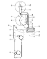
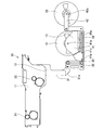
- FIG. 2 schematically shows a schematic configuration of the tape feeder 10.
- the left side of the paper (the side on which the electronic component mounting machine 1 is present when mounted on the electronic component mounting machine 1) is the front side, and the right side of the paper is the rear side.
- the upper side of the paper (when mounted on the electronic component mounting machine 1, the upper side in the vertical direction) is the upper side, the lower side of the paper is the lower side, and the depth direction of the paper is the transport direction of the circuit board.
- the tape feeder 10 includes a feeder body 11, a movable mechanism 12, and a reel holding unit 13.
- the tape feeder 10 is of a type called an auto loading feeder and holds two reels 51 and 52.
- the first reel 51 is wound with a first tape (hereinafter referred to as a delivery tape) that holds electronic components at a constant pitch interval.
- the second reel 52 is wound with a second tape (hereinafter referred to as a standby tape) that holds electronic components at a constant pitch interval.
- the electronic components held on the delivery tape and the electronic components held on the standby tape are the same type.
- the first reel 51 and the second reel 52 are held at different positions in the reel holding surface orthogonal to the circuit board transport direction.
- the reel holding surface is also a surface on which the feeder main body 11 exists.
- the feeder body 11 is configured to be detachable from the frame of the electronic component supply device 5 and includes a first sprocket 21 and a second sprocket 22.
- the first sprocket 21 and the second sprocket 22 are configured to be rotatable in synchronization.
- the first sprocket 21 and the second sprocket 22 engage with a feed hole formed in the delivery tape from the first reel 51 and pitch-feed the delivery tape to a component suction position along a tape guide (not shown). .
- the leading end of the standby tape from the second reel 52 stands by above the second sprocket 22.
- the feeder body 11 moves the standby tape waiting above the second sprocket 22 downward, and engages the second sprocket 22 with the feed hole formed in the standby tape.
- the feeder main body 11 is configured to automatically send the standby tape to the electronic component mounting machine 1 after the delivery tape is consumed.
- the splicing work of the tape that has been performed manually until now can be performed. Can be omitted.
- the work efficiency of the operator is improved and the production stop of the splicing work is lost or the production stop due to the work mistake is eliminated, so that the production efficiency of the electronic component mounting machine 1 is improved.
- the movable mechanism 12 is configured to allow relative movement of the reel holding unit 13 with respect to the feeder main body 11, and includes a support arm 31, a pair of links 32 and 33, and a guide arm 34.
- the support arm 31 has an upper end fixed to the rear end of the feeder main body 11, extends parallel to the reel holding surface, and extends downward from the rear end of the feeder main body 11.
- the lower end portion of the support arm 31 has a connecting portion 31a extending rearward.
- the first link 32 extends parallel to the reel holding surface, one end is rotatably connected to the connecting portion 31 a of the support arm 31, and the other end is rotatable to the front end portion of the guide arm 34. It is connected to.
- the second link 33 also extends parallel to the reel holding surface, and one end is rotatably connected to the connecting portion 31 a of the support arm 31, and the other end is rotatable to the front end portion of the guide arm 34. It is connected to. Between the connecting portion 31a of the support arm 31 and the guide arm 34, the first link 32 and the second link 33 have the same length. Thereby, the guide arm 34 is configured to be movable in a plane parallel to the reel holding surface.
- FIGS. 2 and 3 show how the guide arm 34 moves in parallel.
- the movable mechanism 12 translates the guide arm 34 by using a pair of links 32 and 33, so that the position of the reel holding unit 13 with respect to the feeder body 11 is set to an upper position (see FIG. 2) and a lower position (see FIG. 3)).
- the presence range when the reel holding unit 13 and the pair of reels 51 and 52 are in the upper position is that the reel holding unit 13 and the pair of reels 51 and 52 are in the lower position. It does not overlap with the existing range. Therefore, as shown in FIG. 1, when the plurality of tape feeders 10 are mounted on the electronic component mounting machine 1, the reel holding unit 13 disposed at the upper position and the reel holding unit disposed at the lower position.
- the contact of the reel holding part 13 between the adjacent tape feeders 10 can be avoided. Since the reel holding unit 13 is configured to be wider than the feeder body 11, the number of tape feeders 10 that can be mounted on the electronic component mounting machine 1 can be increased by avoiding contact with the reel holding unit 13.
- the width of the feeder main body 11 is not limited to 13 but is limited. As a result, a larger number of tape feeders 10 can be mounted on the electronic component mounting machine 1, so that the electronic component mounting machine 1 can mount many types of electronic components on the circuit board.
- the reel holding unit 13 includes a first holding unit 41 and a second holding unit 42.
- the first holding unit 41 is disposed closer to the feeder body 11 than the second holding unit 42.
- the first holding portion 41 has an engagement pin 41 a, and the engagement pin 41 a engages with the rotation shaft hole of the first reel 51 to hold the first reel 51 rotatably.
- the second holding part 42 is disposed on the side farther from the feeder body 11 than the first holding part 41, and is configured by a rectangular plate member.
- the front end of the second holding part 42 is connected to the first holding member 41 so as to be rotatable.
- the second holding portion 42 also has an engagement pin 42a at the rear end portion, and the engagement pin 42a engages with the rotation shaft hole of the second reel 52 to hold the second reel 52 rotatably. .
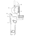
- the second holding portion 42 is located at a position where the longitudinal direction thereof is parallel to the front-rear direction, in other words, when the engaging pin 42a is at a position furthest away from the engaging pin 41a of the first holding portion 41. 52 is held stably.
- the second holding unit 42 is the first holding unit. It is folded to 41 side and stored in the side of the 1st holding
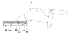
- the first holding part 41 has a pair of rollers 41b and 41c.
- the pair of rollers 41 a and 41 b are inserted into an opening 34 a formed in the guide arm 34 with the conveyance direction of the circuit board as a rotation axis.
- the opening 34a of the guide arm 34 extends along the front-rear direction.
- the pair of rollers 41 a and 41 b move while being guided by the opening 34 a of the guide arm 34.
- the reel holding unit 13 is configured to be slidable in the front-rear direction along the guide arm 34 and is configured to be movable between an approaching position approaching the feeder body 11 and a separating position separating. Yes.
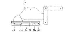
- FIG. 5A schematically shows an enlarged view of the main part of the rear end portion of the guide arm 34.
- the opening 34a of the guide arm 34 is formed with a pair of grooves 35, 36 including an upper groove 35 formed on the upper edge that defines the opening 34a and a lower groove 36 formed on the lower edge that defines the opening 34a. ing.
- the upper groove 35 is formed in front of the lower groove 36. Since the reel holder 13 is formed to extend rearward from the pair of rollers 41a and 41b, a self-weight torque in the clockwise direction is generated in the reel holder 13 with the pair of rollers 41a and 41b as the rotation shaft. Therefore, as shown in FIG.
- the tape feeder 10 of this embodiment can automatically supply the standby tape from the second reel 52 to the electronic component mounting machine 1 after the feeding tape from the first reel 51 is consumed. it can. Further, before the standby tape from the second reel 52 is consumed, the operator takes out the first reel 51 from which the feed tape has been consumed from the first holding unit 41 and holds the second reel 52 in the first holding state. The second holding unit 42 is replenished with a new reel. Thereby, since it is not necessary to stop production for reel replacement, the production efficiency of the electronic component mounting machine 1 is improved.
- the reel holding unit 13 arranged at the upper position and the reel holding unit 13 arranged at the lower position are alternately arranged along the conveyance direction of the circuit board. Is set to be For this reason, in particular, the first holding portion 41 of the reel holding portion 13 disposed at the lower position is blocked by the reel holding portion 13 disposed at the upper position when observed by the operator.
- the reel holding portion 13 is configured to be movable between an approach position and a separation position. As a result, when the reel holding part 13 arranged at the lower position is placed at the separated position, the reel holding part 13 is exposed from the reel holding part 13 arranged at the upper position. The held reel can be easily exchanged.
- the guide arm 34 is translated between the upper position and the lower position using the pair of links 32 and 33.
- the guide arm 34 may be moved between an upper position and a lower position using an attachment / detachment mechanism.
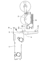
- the support arm 31 of this example has a pair of upper engagement hooks 37a and a pair of lower engagement hooks 37b.
- the guide arm 34 has a pair of engagement pins 38 formed at the front end. The guide arm 34 is disposed at the upper position when the pair of engagement pins 38 engage with the upper engagement hook 37a, and is disposed at the lower position when the pair of engagement pins 38 engage with the lower engagement hook 37b.
- the Such an attaching / detaching mechanism is characterized in that its form is simplified and it is resistant to breakage.
Landscapes
- Engineering & Computer Science (AREA)
- Manufacturing & Machinery (AREA)
- Microelectronics & Electronic Packaging (AREA)
- Supply And Installment Of Electrical Components (AREA)
Abstract
Description
11:フィーダ本体
12:可動機構
13:リール保持部
21:第1スプロケット
22:第2スプロケット
31:支持アーム
32:第1リンク
33:第2リンク
34:案内アーム
41:第1保持部
42:第2保持部
51:第1リール
52:第2リール
Claims (7)
- 基板作業機に電子部品を供給するテープフィーダであって、
電子部品を保持する第1テープが巻回されている第1リール及び電子部品を保持する第2テープが巻回されている第2リールをリール保持面内の異なる位置で保持するリール保持部と、
前記第1リールからの前記第1テープを前記基板作業機に送出するとともに、前記第1テープが消費された後に前記第2リールからの前記第2テープを自動的に前記基板作業機に送出するフィーダ本体と、
前記リール保持部と前記フィーダ本体との間に設けられており、前記フィーダ本体に対する前記リール保持部の相対移動を許容する可動機構と、
を備え、
前記可動機構は、前記フィーダ本体に対する前記リール保持部の位置を、上側位置と下側位置との間で変更可能にするとともに、少なくとも前記下側位置において接近位置と離間位置との間で変更可能にする、
テープフィーダ。 - 前記可動機構は、前記リール保持面に対して平行に伸びる案内部を含む案内アームを有しており、
前記リール保持部は、前記案内部に沿って前記接近位置と前記離間位置との間で摺動可能に構成されている、
請求項1に記載のテープフィーダ。 - 前記案内アームは、前記リール保持部が前記上側位置に配置されるときの位置と前記リール保持部が前記下側位置に配置されるときの位置との間を平行移動可能に構成されている、請求項2に記載のテープフィーダ。
- 前記可動機構は、前記案内アームが選択的に着脱される第1着脱部と第2着脱部とを有しており、
前記案内アームが前記第1着脱部に取り付けられると、前記リール保持部が前記上側位置に配置され、
前記案内アームが前記第2着脱部に取り付けられると、前記リール保持部が前記下側位置に配置される、
請求項2に記載のテープフィーダ。 - 前記案内アームには、前記案内部として前記リール保持部の摺動方向に沿って伸びる開口が形成されており、
前記開口には、前記開口を画定する下縁に形成されている下溝と前記開口を画定する上縁に形成されている上溝とを含む一対の溝が形成されており、
前記リール保持部は、前記案内アームの前記開口に挿入されている一対のローラを有しており、
前記フィーダ本体に対する前記リール保持部の位置は、前記一対のローラの一方が前記下溝に嵌入するとともに他方が前記上溝に嵌入すると固定される、
請求項2~4のいずれか一項に記載のテープフィーダ。 - 前記一対の溝は、前記案内アームの前記開口の一方の端部と他方の端部のそれぞれに形成されており、
前記一対のローラが前記開口の一方の端部に形成されている前記一対の溝に嵌入すると、前記リール保持部が前記接近位置に配置され、
前記一対のローラが前記開口の他方の端部に形成されている前記一対の溝に嵌入すると、前記リール保持部が前記離間位置に配置される、
請求項5に記載のテープフィーダ。 - 前記リール保持部は、第1保持部と第2保持部とを有しており、
前記第1保持部は、前記第1リールを保持するように構成されており、
前記第2保持部は、前記第1保持部よりも前記フィーダ本体から遠い側に配置されており、前記第2リールを保持する通常位置と前記フィーダ本体に接近するとともに前記第2リールを保持しない格納位置との間を移動可能に構成されている、
請求項1~6のいずれか一項に記載のテープフィーダ。
Priority Applications (5)
| Application Number | Priority Date | Filing Date | Title |
|---|---|---|---|
| EP14896345.7A EP3166376B1 (en) | 2014-07-04 | 2014-07-04 | Tape feeder |
| CN201480080172.2A CN106471876B (zh) | 2014-07-04 | 2014-07-04 | 带式供料器 |
| PCT/JP2014/067979 WO2016002085A1 (ja) | 2014-07-04 | 2014-07-04 | テープフィーダ |
| JP2016530795A JP6545677B2 (ja) | 2014-07-04 | 2014-07-04 | テープフィーダ |
| US15/323,447 US10375868B2 (en) | 2014-07-04 | 2014-07-04 | Tape feeder |
Applications Claiming Priority (1)
| Application Number | Priority Date | Filing Date | Title |
|---|---|---|---|
| PCT/JP2014/067979 WO2016002085A1 (ja) | 2014-07-04 | 2014-07-04 | テープフィーダ |
Publications (1)
| Publication Number | Publication Date |
|---|---|
| WO2016002085A1 true WO2016002085A1 (ja) | 2016-01-07 |
Family
ID=55018681
Family Applications (1)
| Application Number | Title | Priority Date | Filing Date |
|---|---|---|---|
| PCT/JP2014/067979 Ceased WO2016002085A1 (ja) | 2014-07-04 | 2014-07-04 | テープフィーダ |
Country Status (5)
| Country | Link |
|---|---|
| US (1) | US10375868B2 (ja) |
| EP (1) | EP3166376B1 (ja) |
| JP (1) | JP6545677B2 (ja) |
| CN (1) | CN106471876B (ja) |
| WO (1) | WO2016002085A1 (ja) |
Cited By (5)
| Publication number | Priority date | Publication date | Assignee | Title |
|---|---|---|---|---|
| US20180049353A1 (en) * | 2015-04-03 | 2018-02-15 | Yamaha Hatsudoki Kabushiki Kaisha | Setup supporting device, component mounter, setup supporting method |
| WO2018207329A1 (ja) * | 2017-05-11 | 2018-11-15 | ヤマハ発動機株式会社 | 部品供給台車および部品実装装置 |
| WO2020003424A1 (ja) * | 2018-06-27 | 2020-01-02 | ヤマハ発動機株式会社 | 部品供給装置 |
| WO2020084663A1 (ja) | 2018-10-22 | 2020-04-30 | 株式会社Fuji | 電気部品供給装置、および電気部品供給方法 |
| JPWO2022219715A1 (ja) * | 2021-04-13 | 2022-10-20 |
Families Citing this family (3)
| Publication number | Priority date | Publication date | Assignee | Title |
|---|---|---|---|---|
| JP7129610B2 (ja) * | 2018-03-30 | 2022-09-02 | パナソニックIpマネジメント株式会社 | 部品供給ユニットの配置決定方法および部品供給ユニットの配置決定装置 |
| JP6806743B2 (ja) * | 2018-08-24 | 2021-01-06 | ファナック株式会社 | リールホルダ、テープ供給装置、ロボットハンド、ロボットおよび部品実装システム |
| US12624853B2 (en) | 2020-02-14 | 2026-05-12 | Blueair Ab | Air purifier |
Citations (3)
| Publication number | Priority date | Publication date | Assignee | Title |
|---|---|---|---|---|
| JP2004047951A (ja) * | 2002-05-24 | 2004-02-12 | Fuji Mach Mfg Co Ltd | テープフィーダおよび電子部品供給システム |
| JP2006108420A (ja) * | 2004-10-06 | 2006-04-20 | Matsushita Electric Ind Co Ltd | 電子部品供給装置 |
| JP2014082454A (ja) * | 2012-09-25 | 2014-05-08 | Fuji Mach Mfg Co Ltd | フィーダ |
Family Cites Families (8)
| Publication number | Priority date | Publication date | Assignee | Title |
|---|---|---|---|---|
| US5873691A (en) * | 1995-05-11 | 1999-02-23 | Fuji Machine Mfg. Co., Ltd. | Electronic-component supplying system |
| JP2010212681A (ja) * | 2009-03-09 | 2010-09-24 | Koshoku Kin | 部品実装機用キャリアテープ自動供給装置 |
| US8678065B2 (en) * | 2010-03-30 | 2014-03-25 | Sts Co., Ltd. | Carrier tape feeder |
| JP5891354B2 (ja) * | 2012-01-19 | 2016-03-23 | パナソニックIpマネジメント株式会社 | テープフィーダ及び部品実装装置 |
| JP5891353B2 (ja) * | 2012-01-19 | 2016-03-23 | パナソニックIpマネジメント株式会社 | テープフィーダ及び部品実装装置 |
| JP6114509B2 (ja) * | 2012-06-28 | 2017-04-12 | ヤマハ発動機株式会社 | 部品供給装置及び部品実装装置 |
| US10660249B2 (en) * | 2015-09-09 | 2020-05-19 | Fuji Corporation | Separate installation-type reel holding device |
| CN108293318B (zh) * | 2015-11-30 | 2020-06-30 | 株式会社富士 | 元件供给装置的电源控制装置及电源控制方法 |
-
2014
- 2014-07-04 US US15/323,447 patent/US10375868B2/en active Active
- 2014-07-04 WO PCT/JP2014/067979 patent/WO2016002085A1/ja not_active Ceased
- 2014-07-04 CN CN201480080172.2A patent/CN106471876B/zh active Active
- 2014-07-04 JP JP2016530795A patent/JP6545677B2/ja active Active
- 2014-07-04 EP EP14896345.7A patent/EP3166376B1/en active Active
Patent Citations (3)
| Publication number | Priority date | Publication date | Assignee | Title |
|---|---|---|---|---|
| JP2004047951A (ja) * | 2002-05-24 | 2004-02-12 | Fuji Mach Mfg Co Ltd | テープフィーダおよび電子部品供給システム |
| JP2006108420A (ja) * | 2004-10-06 | 2006-04-20 | Matsushita Electric Ind Co Ltd | 電子部品供給装置 |
| JP2014082454A (ja) * | 2012-09-25 | 2014-05-08 | Fuji Mach Mfg Co Ltd | フィーダ |
Cited By (15)
| Publication number | Priority date | Publication date | Assignee | Title |
|---|---|---|---|---|
| US10912240B2 (en) * | 2015-04-03 | 2021-02-02 | Yamaha Hatsudoki Kabushiki Kaisha | Setup supporting device, component mounter, setup supporting method |
| US20180049353A1 (en) * | 2015-04-03 | 2018-02-15 | Yamaha Hatsudoki Kabushiki Kaisha | Setup supporting device, component mounter, setup supporting method |
| WO2018207329A1 (ja) * | 2017-05-11 | 2018-11-15 | ヤマハ発動機株式会社 | 部品供給台車および部品実装装置 |
| JPWO2018207329A1 (ja) * | 2017-05-11 | 2019-12-12 | ヤマハ発動機株式会社 | 部品供給台車および部品実装装置 |
| JP7093837B2 (ja) | 2018-06-27 | 2022-06-30 | ヤマハ発動機株式会社 | 部品供給装置 |
| JPWO2020003424A1 (ja) * | 2018-06-27 | 2021-06-03 | ヤマハ発動機株式会社 | 部品供給装置 |
| WO2020003424A1 (ja) * | 2018-06-27 | 2020-01-02 | ヤマハ発動機株式会社 | 部品供給装置 |
| US11974402B2 (en) | 2018-06-27 | 2024-04-30 | Yamaha Hatsudoki Kabushiki Kaisha | Component supply device |
| WO2020084663A1 (ja) | 2018-10-22 | 2020-04-30 | 株式会社Fuji | 電気部品供給装置、および電気部品供給方法 |
| JPWO2020084663A1 (ja) * | 2018-10-22 | 2021-03-18 | 株式会社Fuji | 電気部品供給装置、および電気部品供給方法 |
| JP7012868B2 (ja) | 2018-10-22 | 2022-01-28 | 株式会社Fuji | 電気部品供給装置、および電気部品供給方法 |
| US11903136B2 (en) | 2018-10-22 | 2024-02-13 | Fuji Corporation | Electric component supply device, and electric component supply method |
| JPWO2022219715A1 (ja) * | 2021-04-13 | 2022-10-20 | ||
| WO2022219715A1 (ja) * | 2021-04-13 | 2022-10-20 | 株式会社Fuji | フィーダ及び部品実装機 |
| JP7615306B2 (ja) | 2021-04-13 | 2025-01-16 | 株式会社Fuji | フィーダ及び部品実装機 |
Also Published As
| Publication number | Publication date |
|---|---|
| JPWO2016002085A1 (ja) | 2017-04-27 |
| US10375868B2 (en) | 2019-08-06 |
| JP6545677B2 (ja) | 2019-07-17 |
| EP3166376B1 (en) | 2019-11-27 |
| US20170142873A1 (en) | 2017-05-18 |
| EP3166376A4 (en) | 2017-07-19 |
| EP3166376A1 (en) | 2017-05-10 |
| CN106471876A (zh) | 2017-03-01 |
| CN106471876B (zh) | 2019-04-23 |
Similar Documents
| Publication | Publication Date | Title |
|---|---|---|
| JP6545677B2 (ja) | テープフィーダ | |
| CN107950083B (zh) | 追加型带盘保持装置 | |
| JP5781686B2 (ja) | 作業ヘッド、および、トップテープ剥離装置 | |
| CN107950085B (zh) | 另置式带盘保持装置 | |
| CN110583106B (zh) | 元件供给台车及元件安装装置 | |
| WO2013031565A1 (ja) | 部品供給装置 | |
| EP3809810A1 (en) | Exchange device | |
| WO2008044638A1 (en) | Part feeder, and surface mounting machine | |
| JP7035262B2 (ja) | 追加形リール保持装置 | |
| JP6600185B2 (ja) | テープフィーダ | |
| WO2017098628A1 (ja) | リール保持装置 | |
| JP6777792B2 (ja) | テープフィーダ | |
| JP7047041B2 (ja) | テープフィーダ | |
| JP4969398B2 (ja) | 表面実装装置 | |
| JP5844116B2 (ja) | テープフィーダ | |
| CN113170605A (zh) | 安装系统 | |
| CN103766018B (zh) | 带式供料器 | |
| JP5877211B2 (ja) | 電子部品供給装置 | |
| JP7234433B2 (ja) | 追加形リール保持装置 | |
| US11445648B2 (en) | Feeder | |
| CN110050522B (zh) | 带式供料器 |
Legal Events
| Date | Code | Title | Description |
|---|---|---|---|
| 121 | Ep: the epo has been informed by wipo that ep was designated in this application |
Ref document number: 14896345 Country of ref document: EP Kind code of ref document: A1 |
|
| ENP | Entry into the national phase |
Ref document number: 2016530795 Country of ref document: JP Kind code of ref document: A |
|
| REEP | Request for entry into the european phase |
Ref document number: 2014896345 Country of ref document: EP |
|
| WWE | Wipo information: entry into national phase |
Ref document number: 2014896345 Country of ref document: EP |
|
| WWE | Wipo information: entry into national phase |
Ref document number: 15323447 Country of ref document: US |
|
| NENP | Non-entry into the national phase |
Ref country code: DE |