WO2016002373A1 - Capteur de réflexion optique et dispositif électronique - Google Patents
Capteur de réflexion optique et dispositif électronique Download PDFInfo
- Publication number
- WO2016002373A1 WO2016002373A1 PCT/JP2015/064596 JP2015064596W WO2016002373A1 WO 2016002373 A1 WO2016002373 A1 WO 2016002373A1 JP 2015064596 W JP2015064596 W JP 2015064596W WO 2016002373 A1 WO2016002373 A1 WO 2016002373A1
- Authority
- WO
- WIPO (PCT)
- Prior art keywords
- light
- light receiving
- signal
- distance measuring
- time
- Prior art date
- Legal status (The legal status is an assumption and is not a legal conclusion. Google has not performed a legal analysis and makes no representation as to the accuracy of the status listed.)
- Ceased
Links
Images




Classifications
-
- G—PHYSICS
- G01—MEASURING; TESTING
- G01S—RADIO DIRECTION-FINDING; RADIO NAVIGATION; DETERMINING DISTANCE OR VELOCITY BY USE OF RADIO WAVES; LOCATING OR PRESENCE-DETECTING BY USE OF THE REFLECTION OR RERADIATION OF RADIO WAVES; ANALOGOUS ARRANGEMENTS USING OTHER WAVES
- G01S7/00—Details of systems according to groups G01S13/00, G01S15/00, G01S17/00
- G01S7/48—Details of systems according to groups G01S13/00, G01S15/00, G01S17/00 of systems according to group G01S17/00
- G01S7/483—Details of pulse systems
- G01S7/486—Receivers
- G01S7/4865—Time delay measurement, e.g. time-of-flight measurement, time of arrival measurement or determining the exact position of a peak
-
- G—PHYSICS
- G01—MEASURING; TESTING
- G01S—RADIO DIRECTION-FINDING; RADIO NAVIGATION; DETERMINING DISTANCE OR VELOCITY BY USE OF RADIO WAVES; LOCATING OR PRESENCE-DETECTING BY USE OF THE REFLECTION OR RERADIATION OF RADIO WAVES; ANALOGOUS ARRANGEMENTS USING OTHER WAVES
- G01S17/00—Systems using the reflection or reradiation of electromagnetic waves other than radio waves, e.g. lidar systems
- G01S17/02—Systems using the reflection of electromagnetic waves other than radio waves
- G01S17/06—Systems determining position data of a target
- G01S17/08—Systems determining position data of a target for measuring distance only
- G01S17/10—Systems determining position data of a target for measuring distance only using transmission of interrupted, pulse-modulated waves
-
- G—PHYSICS
- G01—MEASURING; TESTING
- G01C—MEASURING DISTANCES, LEVELS OR BEARINGS; SURVEYING; NAVIGATION; GYROSCOPIC INSTRUMENTS; PHOTOGRAMMETRY OR VIDEOGRAMMETRY
- G01C3/00—Measuring distances in line of sight; Optical rangefinders
- G01C3/02—Details
- G01C3/06—Use of electric means to obtain final indication
- G01C3/08—Use of electric radiation detectors
-
- G—PHYSICS
- G01—MEASURING; TESTING
- G01S—RADIO DIRECTION-FINDING; RADIO NAVIGATION; DETERMINING DISTANCE OR VELOCITY BY USE OF RADIO WAVES; LOCATING OR PRESENCE-DETECTING BY USE OF THE REFLECTION OR RERADIATION OF RADIO WAVES; ANALOGOUS ARRANGEMENTS USING OTHER WAVES
- G01S17/00—Systems using the reflection or reradiation of electromagnetic waves other than radio waves, e.g. lidar systems
- G01S17/02—Systems using the reflection of electromagnetic waves other than radio waves
- G01S17/06—Systems determining position data of a target
- G01S17/46—Indirect determination of position data
- G01S17/48—Active triangulation systems, i.e. using the transmission and reflection of electromagnetic waves other than radio waves
Definitions
- the present invention relates to a reflective sensor that detects the presence or absence of an object and the distance of an object, and an electronic device using the same.
- Patent Document 1 Japanese Patent Laid-Open No. 2013-113610
- Patent Document 2 Japanese Patent Laid-Open No. 2013-210315
- Patent Document 3 Japanese Patent Laid-Open No. 2012-63173
- Patent Document 4 Japanese Patent Laid-Open No. 2-61510
- Patent Document 5 Japanese Patent Laid-Open No. 2013-134173
- radiation from a radiation source is detected by changing the position and orientation of a two-dimensional radiation detector having directivity, and the obtained radiation is detected.
- a radiation source location is estimated by expressing an angle region on a measurement space voxelized.
- the return light condensing optical system includes a return light condensing lens, and the return light condensing lens includes a laser light output element.
- the laser beam emitted and reflected by the scanning mirror includes an optical path toward the irradiation point, and has an optical characteristic in which the refractive power in the width direction in the plane perpendicular to the scanning surface is larger than the refractive power in the scanning surface direction.
- the return light from the irradiation point is received and condensed on the scanning mirror. In this way, a large amount of return light can be obtained, and an effective range of distance measurement can be sufficiently obtained.
- the laser light from the laser diode is deflected by a two-dimensional scanner including a mirror to irradiate the vertex of an arbitrary polygon on the measurement object. . Then, the laser beam reflected at each vertex is received by a photodiode and a signal is output, and the operation control unit uses the output signal from the photodiode and the operation information of the two-dimensional scanner to output the polygon. The area is calculated.
- the reflected light is condensed by the light receiving lens and imaged on the image sensor.
- a focusing lens for converging light is arranged between the light receiving lens and the image sensor only in a direction perpendicular to the detection line of the image sensor, and the central portion of the fine light beams deflected to a certain width is arranged.
- the reflected light of the fine light beam deviated from the vertical direction is imaged on the image sensor, so that the one-dimensional image sensor can measure the distance in the two-dimensional direction.
- the incident is performed in the first light receiving period, which is a part of the rising period of the intensity of the reflected light from the distance measuring object incident on the solid-state imaging device.
- the photoelectrons corresponding to the light quantity of the accumulated light are accumulated and accumulated by the solid-state imaging device.
- photoelectrons corresponding to the amount of incident light are accumulated and accumulated by the solid-state imaging device in a second light receiving period that is a period including a falling period from the peak of the intensity of the reflected light incident on the solid-state imaging device.
- the arithmetic unit divides the photoelectron information accumulated and accumulated during the second light receiving period by the photoelectron information accumulated and accumulated during the first light receiving period to obtain the light amount ratio as a value depending on the round trip time of light.
- the distance to the distance measuring object is obtained by a time of flight (TOF) method.
- photoelectrons corresponding to the amount of light received in a light receiving period other than the light receiving period to be measured are discarded.
- the output current is the far side output current and the near side output current at the light incident position in the PSD (Position Sensitive Detector).
- the distance to the detection objects A and B can be obtained by the triangulation method.
- the center of gravity of the reflected light is shifted and the distance is accurately measured. Can not do it.
- the detected object C is at the same distance as the detected object A, but the PSD incident angle of the reflected light from the detected object C is the same as the PSD incident angle of the detected object B.
- the PSD output current in the case of C becomes the PSD output current in the case of the detection object B, which causes a problem of erroneous detection.
- the distance to the object can be obtained from the time of flight from when the light is emitted from the light emitting unit to when it is reflected by the object and incident on the light receiving unit.
- the object in front of the projection is the object of distance measurement. Therefore, when the detection range is expanded in a plane, the mirror is driven to change the light projection angle with a mirror or the like, and the direction of the light projection is specified based on the mirror angle. is necessary. Alternatively, it is possible to arrange a plurality of light receiving elements and specify the direction of the object according to the position of the light receiving element that has received the incident light. It becomes.
- the light amount ratio is used for calculating the distance to the distance measuring object by the TOF method. Further, photoelectrons corresponding to the amount of light received in a light receiving period other than the light receiving period to be measured are discarded.
- the distance measurement object in front of the irradiation apparatus is the object of distance measurement, and the distance to the distance measurement object in a wide area is not calculated. For this reason, in order to widen the distance measurement range, scanning is performed by changing the irradiation angle with a mirror or the like. Alternatively, it is necessary to arrange a plurality of the individual imaging devices.
- an object of the present invention is to provide a reflective sensor that can detect the presence / absence of an object on a two-dimensional plane and a wide range of the distance of the object with a small and simple configuration.
- the light reflection type sensor of the present invention is: A light emitting element for irradiating light to a distance measuring object; A light receiving optical system for collecting the reflected light from the object to be measured; A light receiving element that receives the light collected by the light receiving optical system and outputs a photocurrent signal according to a light receiving position; Based on the photocurrent signal output from the light receiving element, light receiving position information on the light receiving element and light emitted from the light emitting element are reflected by the object to be measured and are reflected by the light receiving element. And a signal processing circuit for obtaining time-of-flight information, which is a time until light is received.
- the light emitted by the light emitting element is pulsed light
- the light receiving element is a position detecting element
- the photocurrent signal is output from a first photocurrent signal output from an electrode provided on one side of the light receiving position and a second output output from an electrode provided on the other side.
- a control unit that outputs a pulsed drive signal to the light emitting element and outputs a synchronization signal synchronized with a fall of the drive signal to the signal processing circuit
- the signal processing circuit is While obtaining the light receiving position information by the ratio of the integrated value of the first photocurrent signal and the integrated value of the second photocurrent signal output from the light receiving element,
- the first photocurrent signal and the second photocurrent signal are divided into two, and the first photocurrent signal and the second photocurrent signal on the time axis front side from the division position.
- Time-of-flight information of the light is obtained by a ratio between the sum of the integrated values and the sum of the integrated values of the first photocurrent signal and the second photocurrent signal on the time axis rearward from the division position. It is like that.
- the light emitting element is adapted to irradiate light having a radiation angle
- the distance measuring object is located within the radiation angle of the light emitting element, Position information based on the light receiving optical system of the distance measuring object from the incident angle of the reflected light from the distance measuring object to the light receiving element and the flight time information of the light related to the distance measuring object
- a storage unit for storing an arithmetic expression for calculating Based on the light receiving position information obtained by the signal processing circuit, the incident angle of the reflected light from the distance measuring object is obtained, and the obtained incident angle and the light obtained by the signal processing circuit are obtained.
- an arithmetic processing unit that calculates the position information of the distance measuring object using the arithmetic expression stored in the storage unit based on the flight time information.
- a controller that outputs a pulsed drive signal to the light emitting element;
- the signal processing circuit When the photocurrent signal rises, the drive signal and the photocurrent Based on the signal, the light receiving position information and the time-of-flight information of the closest distance measuring object closest to the light receiving optical system among the plurality of distance measuring objects are obtained, while the fall of the photocurrent signal is obtained.
- the arithmetic processing unit obtains the incident angle of the reflected light with respect to the nearest distance measuring object and the farthest distance measuring object based on the respective light receiving position information obtained by the signal processing circuit, Based on the obtained incident angle and the time-of-flight information of the light obtained by the signal processing circuit, position information based on the light receiving optical system is calculated.
- the electronic device of the present invention is The light reflection type sensor of the present invention is used.
- the light reflection type sensor is the light receiving sensor for obtaining the incident angle to the light receiving element based on the photocurrent signal output from the light receiving element by the signal processing circuit.
- the light receiving position information on the element and the time-of-flight information of the upper light are obtained. Accordingly, it is possible to compensate for the shortcomings of the distance measuring method using the triangular distance measuring method and the TOF method, and to increase the detection accuracy of the distance to the distance measuring object. Furthermore, it is possible to prevent erroneous detection when only one of the incident angle and the time of flight of the light is used.
- the configuration of the optical system in the light reflection type sensor of the present invention includes only one light emitting element capable of emitting light in a wide area, the above light receiving optical system, and only one light receiving element, and changes the irradiation angle. There is no need to provide a mirror or the like for scanning and to arrange a plurality of the light emitting elements and the light receiving elements. Therefore, it is possible to detect a wide area on a two-dimensional plane with a small and simple configuration.
- the electronic device of the present invention uses an inexpensive reflective sensor that can detect the presence or absence of an object in a two-dimensional plane and a wide range of the distance of the object with high accuracy with a small and simple configuration. It is possible to provide a comfortable electronic device that is gentle to people and the environment by being used for sanitary applications, robot cleaners, and devices that require human body detection.
- FIG. 5 is a diagram showing a drive signal to the light emitting element and a detection signal of the light receiving element in FIG. 4. It is explanatory drawing of how to obtain
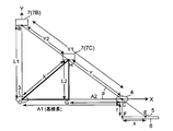
- FIG. 1 is a schematic diagram illustrating a configuration of a light reflection type sensor according to the present embodiment.
- the light reflection type sensor according to the present embodiment has a configuration that combines the triangular distance measuring method and the TOF method.
- a light reflection type sensor 1 includes a light emitting element 2 composed of the LED for irradiating light to a distance measuring object 7 (hereinafter simply referred to as an object), and a light emitting element 2.
- the light-emitting lens 3 that collects the reflected light
- the light-receiving lens 4 that collects the reflected light from the object 7, and the light that is collected by the light-receiving lens 4 is imaged to form a light spot 5.
- an element 6 The light emitting element 2 may be another element such as an infrared light emitting element or a laser diode.
- the position of the light emitting lens 3 is the origin O
- the irradiation position of the light from the light emitting element 2 on the object 7 (7A) is A
- the position of the light receiving lens 4 is the point C
- X is on the base line of the origin O.
- the light receiving element 6 is arranged on a straight line parallel to the axis.
- the PSD is used for the light receiving element 6 and detects the position of the light barycenter of the light spot 5 irradiated and imaged on the light receiving element 6 and outputs a detection signal.
- the signal processing circuit 8 obtains the position of the light spot 5 on the light receiving element 6 and the time from when the light is emitted from the light emitting element 2 until the light spot 5 is formed on the light receiving element 6.
- the flight time (hereinafter simply referred to as the flight time) is obtained.
- the arithmetic processing unit 9 Based on the position of the light spot 5 obtained by the signal processing circuit 8, the arithmetic processing unit 9 passes the incident angle of the reflected light from the object 7 to the light receiving element 6 and the light emitting lens 3 and the light receiving lens 4. The distance from the base line which is a straight line to the object 7 is calculated.
- the storage unit 10 stores a flight time search table that will be described in detail later.
- the control unit 11 receives the calculation result from the arithmetic processing unit 9 and controls the operations of the light emitting element 2 and the signal processing circuit 8.
- the light beam emitted from the light emitting element 2 to the object 7 (7 ⁇ / b> A) is condensed into a substantially parallel light beam 12 by the light emitting lens 3.
- the condensed parallel light beam 12 is emitted along the Y axis, is spot-irradiated at a point A on the object 7, and is diffusely reflected by the object 7.
- the light beam 13 diffusely reflected by the object 7 is collected by the light receiving lens 4.
- the condensed light is imaged at a point E on the light receiving element 6 to form a light spot 5.
- the triangle OAC and the triangle FCE are similar.
- the distance A is a distance (base line length) between the light emitting lens 3 and the light receiving lens 4.
- the distance f is the distance between the light receiving lens 4 and the light receiving element 6 and is the focal length of the light receiving lens 4.
- the distance x is the amount of change from the reference position of the light barycenter position of the light spot 5 on the light receiving element (PSD) 6.
- the distance x is the detection signal output from the electrodes provided at both ends of the light receiving element 6, and the balance between the signal currents I 1 and I 2 changing according to the change amount is given to the light receiving element 6. It is calculated
- the size of the target is the spread of the light. There is no problem if it is large enough to cover the whole.
- FIG. 1 when there is an object 7C having the same distance from the base line as the object 7A but different from the object 7A, the light reflected from the object 7C to the light receiving element 6 is received. Since the incident angle is the same as the incident angle of the reflected light from the object 7B on the Y axis, the distance x obtained by the signal processing circuit 8 is the same between the object 7C and the object 7B. . Therefore, the distance LC from the base line to the target object 7C is calculated as the distance y (LB) to the target object 7B, resulting in erroneous detection.
- the light detection element 6 and the signal processing circuit 8 are provided with a distance detection function by the TOF method, thereby preventing the erroneous detection by the triangulation method.
- the light is emitted from the light emitting element 2 and then the light is emitted from each object.
- the flight time T which is the time from when reflected by 7 and received by the light receiving element 6, is obtained in advance.
- a flight time search table in which the flight time T is associated with the distance y from the base line to the object 7 and the incident angle ⁇ to the light receiving element 6 is created and stored.
- a drive signal for emitting pulsed light is output from the control unit 11 to the light emitting element 2, and pulsed light is emitted from the light emitting element 2.
- the signal processing circuit 8 outputs a control signal for notifying that the pulsed light has been turned off.
- the signal processing circuit 8 and the arithmetic processing unit 9 receive the detection signal from the light receiving element 6 corresponding to the pulsed light emitted from the light emitting element 2 and enter the light receiving element 6 by the triangular distance measuring method. Find the angle ⁇ . That is, assuming that the irradiation position of light from the light emitting element 2 on the object 7B is B and the position of the light spot 5 formed on the light receiving element 6 is Eb, the triangle OBC and the triangle FCEb are similar. Therefore, the signal processing circuit 8 obtains the position of the light spot 5 based on the detection signal from the light receiving element 6, and measures the length (distance x) of the side FEb. Then, the arithmetic processing unit 9 calculates Tan ⁇ 1 (f / x) for the triangle FCEb to determine the incident angle ⁇ on the light receiving element 6.
- the signal processing circuit 8 emits the pulsed light from the light emitting element 2 based on the detection signal from the light receiving element 6 and the control signal for turning off the pulsed light from the control unit 11.
- the flight time Tc which is the time until the light spot 5 is formed on the light receiving element 6 by the reflected light from the object 7C, is obtained.
- the search result of the flight time search table by the arithmetic processing unit 9 shows that the distance y from the base line to the distance measuring object 7 is LB. Desired. That is, different objects 7 having the same incident angle ⁇ incident on the light receiving element 6 can be distinguished by the difference in the flight time.
- the PSD as the light receiving element 6
- the light is output from both ends of the light receiving element 6 according to the spot position on the light receiving element 6 due to the reflected light from the object 7.
- the spot position on the light receiving element 6 can be detected by the ratio of the detection signals. Therefore, based on the spot position, the incident angle ⁇ of the reflected light from the object 7 can be obtained by the triangulation method.
- the time from when the pulsed light is emitted from the light emitting element 2 to when the detection signal is output from the light receiving element 6 is delayed by the time of flight according to the distance from the base line to the object 7. Therefore, the delay time, that is, the flight time T is detected by a detection signal output from both ends of the light receiving element 6 according to the spot position and a control signal for notifying that the pulsed light is turned off. Based on the incident angle ⁇ and the flight time T, the distance from the base line to the object 7 can be obtained.
- the distance from the light emitting lens 3 to the object 7 depends on the distance between the object 7 and the light receiving lens 4 (that is, the flight time T). The distance to fluctuates. Even if the flight time T is the same, the distance from the light emitting lens 3 to the object 7 varies depending on the angle between the object 7 and the light receiving lens 4 (that is, the incident angle ⁇ ). This is achieved by using the incident angle ⁇ of the reflected light from the object 7 and the time of flight T from when the light is emitted from the light emitting element 2 to when it is received by the light receiving element 6. In addition, it means that the detection accuracy of the distance from the light emitting lens 3 to the object 7 can be increased. Further, it is possible to prevent erroneous detection when only one of the incident angle ⁇ and the flight time T is used.
- the configuration of the optical system in the present light reflection type sensor includes only one light emitting element 2 and light emitting lens 3 that can emit light in a wide area, a light receiving lens 4, and one light receiving element 6 made of the PSD. Therefore, it is not necessary to provide a mirror for scanning by changing the irradiation angle or to arrange a plurality of light emitting elements 2 and light receiving elements 6. Therefore, it is possible to detect a wide area on a two-dimensional plane with a small and simple configuration.
- the accuracy of detecting the position information of the object on the two-dimensional plane can be improved and erroneous detection can be prevented by the light reflection type sensor that projects light with one pulse. is there.
- the length (distance x) of the side FEb is measured based on the detection signal from the light receiving element 6, and the angle of incidence on the light receiving element 6 by Tan ⁇ 1 (f / x) with respect to the triangle FCEb. ⁇ is obtained.
- the present invention is not limited to this, and the length LB of the side OB of the triangle OBC may be obtained by the above-mentioned triangulation method, and the triangle OBC may be obtained by Tan ⁇ 1 (LB / A).
- the signal processing circuit 8 obtains the position of the light spot 5 on the light receiving element 6 and the light spot on the light receiving element 6 after the light is emitted from the light emitting element 2.
- the present invention relates to a method for obtaining the flight time T until 5 is detected.
- FIG. 2 shows, in order from the upper end, the on / off timing of the drive signal output from the control unit 11 to the light emitting element 2 (that is, the on / off state of the light emitting element 2) and the far side of the light receiving element 6. 2 shows a change in the far-side output current that is the detection signal and a change in the near-side output current that is the near-side detection signal in the light receiving element 6.
- the far side of the light receiving element 6 is the side where the reflected light from the object 7 located far away forms the spot 5 in the light receiving element 6 which is a PSD.
- the near side of the light receiving element 6 is the side on the light receiving element 6 where the reflected light from the object 7 located nearby forms the spot 5.
- the far-side output current I1 is an output current output from the far-end electrode of both ends of the light receiving element 6, and its value is "I1".
- the near-side output current I2 is an output current output from the electrode at the near-side end of the light receiving element 6, and its value is "I2".
- the far side output current I1 is an example of the first photocurrent signal
- the near side output current I2 is an example of the second photocurrent signal.
- the far-side output current I1 is divided at the timing when the light emitting element 2 is turned off (falling).
- An integrated value of the output current value I1 in the first light receiving period that is on the time axis front side from the division position is defined as I1a.
- the integrated value of the output current value I1 in the second light receiving period that is on the rear side of the time axis from the division position is defined as I1b.
- the near-side output current I2 is divided at the timing when the light emitting element 2 is turned off (falling).
- An integrated value of the output current value I2 in the first light receiving period that is on the time axis front side from the division position is defined as I2a.
- the integrated value of the output current value I2 in the second light receiving period that is on the rear side of the time axis from the division position is defined as I2b.
- the far side output current I1 and the near side output current I2 increase or decrease in directions opposite to each other. Therefore, the integrated value (I1a + I1b) of the output current value I1 in “first light receiving period + second light receiving period” and the integrated value (I2a + I2b) of output current value I2 in “first light receiving period + second light receiving period” are obtained. By comparing, the position of the spot 5 on the light emitting element 2 can be obtained.
- the flight time T changes between long and short, the division position in the far side output current I1 and the near side output current I2 moves back and forth on the time axis. Therefore, the integrated value (I1a + I2a) of each of the far side output current I1 and the near side output current I2 in the “first light receiving period”, and the far side output current I1 and the near side output current I2 in the “second light receiving period”.
- the flight time T can be obtained by comparing the added value (I2a + I2b) of the respective integral values.
- the signal processing circuit 8 when the signal processing circuit 8 receives the far-side output current I1 and the near-side output current I2 from the light receiving element 6 which is a PSD, the signal processing circuit 8 transmits the control signal to the light emitting element 2 transmitted from the control unit 11. Based on the timing of a synchronizing signal (control signal notifying that the pulsed light has been turned off) synchronized with the falling edge, the far-side output current I1 and the near-side output current I2 are supplied to the first light receiving period and the second light receiving Divide into periods.
- a synchronizing signal control signal notifying that the pulsed light has been turned off
- the integral value (I1a + I1b) of the output current value I1 and the integral value (I2a + I2b) of the output current value I2 are calculated, and the ratio “(I1a + I1b) / (I2a + I2b)” of both integral values is calculated. Based on the value of the ratio, the position of the light spot 5 on the light receiving element 6 is obtained.
- the addition value (I1a + I2a) of the integrated values of both output currents in the “first light receiving period” and the added value (I1b + I2b) of the integrated values of both output currents in the “second light receiving period” are calculated and further added.
- the ratio of values “(I1a + I2a) / (I1b + I2b)” is calculated.
- the flight time T from when the light is emitted from the light emitting element 2 to when the light spot 5 is detected on the light receiving element 6 is obtained.
- the method for obtaining the flight time based on the ratio value is not particularly limited.
- the flight time can be obtained by using a correspondence table or a correspondence formula between the ratio value and the flight time prepared in advance. That's fine.
- a simple process of dividing I2 with the timing of turning off (falling) of the light-emitting element 2 and changing the combination of the four integrated output current values I1a, I1b, I2a, I2b, Position information for obtaining the position of the light spot 5 on the light receiving element 6 and time information for obtaining the flight time T can be obtained.
- the present invention relates to a method for obtaining without using the flight time search table in the first embodiment.
- the signal processing circuit 8 first detects the light spot on the light receiving element 6 based on the far side output current I1 and the near side output current I2 from the light receiving element 6 which is a PSD, for example, by the process of the second embodiment. 5 is obtained, and the length (distance x) of the side FE of the triangle FCE is measured. Further, the arithmetic processing unit 9 uses the fact that the triangle OBC and the triangle FCE are similar to each other on the virtual object 7B on the Y axis passing through the light-emitting lens 3, and the triangular distance measuring method. To calculate the distance L1 from the light emitting lens 3 to the object 7B.
- the distance between the light-emitting lens 3 and the light-receiving lens 4 is the baseline length A1
- the distance between the light-receiving lens 4 and the light-receiving element 6 is the light-receiving lens 4 focal length f, both of which are known.
- Tan ⁇ 1 (L1 / A1) is calculated for the triangle OBC to determine the incident angle ⁇ to the light receiving element 6.
- the signal processing circuit 8 emits light from the light emitting element 2 based on the far side output current I1 and the near side output current I2 from the light receiving element 6, for example, by the process of the second embodiment.
- the flight time T from when the light is reflected by the object 7C until it is received by the light receiving element 6 is obtained.
- the arithmetic processing unit 9 calculates the distance Y from the object 7C to the light receiving element 6 from the above formulas (1) to (4) as the formula (5).
- Y (A1 2 ⁇ T 2 C 2 ) / (2A1 cos ⁇ 2T ⁇ C) (5)
- the distance A2 along the base line from the light receiving lens 4 in the distance measuring object 7C and the base line This distance L2 can be calculated.
- the storage unit 10 stores the equations (1) to (4) instead of the flight time search table.
- the signal processing circuit 8 obtains the position of the light spot 5 on the light receiving element 6 based on the far side output current I1 and the near side output current I2 from the light receiving element 6, and the arithmetic processing unit 9 performs the above operation.
- the incident angle ⁇ of the reflected light from the object 7C to the light receiving element 6 is obtained using a triangulation method.
- the time T of flight from when the light is emitted from the light emitting element 2 to when it is reflected by the object 7C and received by the light receiving element 6 is obtained by the signal processing circuit 8.
- the light receiving lens 4 is used by using the equations (1) to (4) stored in the storage unit 10.
- the position information of the object 7 ⁇ / b> C with reference to is obtained.
- the detection accuracy when detecting the position information of the object 7 on the two-dimensional plane using only one light emitting element 2 capable of emitting light in a wide area compared with the case of using the above flight time search table, Further improvement can be achieved. Furthermore, it is not necessary to create and register the flight time search table, and it is easy to construct a light reflection type sensor.
- the object 7 ⁇ / b> C to be distance-measured is at an intermediate position between the light-emitting lens 3 and the light-receiving lens 4.
- the light receiving lens 4 of the object 7C has the same configuration and processing. It is possible to obtain position information based on.
- This embodiment uses only one light emitting element 2 capable of emitting light in a wide area, and detects position information when a plurality of objects 7 exist within the light emission angle from the light emitting element 2. Regarding the method.
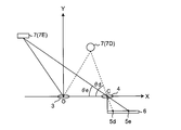
- FIG. 4 shows a positional relationship between the light emitting lens 3, the light receiving lens 4, and the light receiving element 6 and the two objects 7D and 7E in the present embodiment.
- one object 7D is located between the light emitting lens 3 and the light receiving lens 4
- the other object 7E is located on the opposite side of the light receiving lens 3 from the light receiving lens 4 side. ing.
- any of the above objects 7D and 7E is located within the light emission angle from the light emitting element 2, and the reflected light from the object 7D is incident on the long distance detection region side of the light receiving element 6 to enter the light spot 5d. Forming. On the other hand, the reflected light from the object 7E is incident on the short distance detection region side of the light receiving element 6 to form a light spot 5e.
- FIG. 5 shows the drive signal to the light emitting element 2 and the detection signal from the light receiving element 6.
- FIG. 5A shows the on / off timing of the drive signal output from the control unit 11 to the light emitting element 2 (that is, the light emitting element 2 is turned on / off).
- FIG. 5B shows a detection signal from the light receiving element 6 when the object of distance measurement is the objects 7D and 7E.
- FIG. 5C shows a detection signal from the light receiving element 6 when the object of distance measurement is only the object 7D.
- FIG. 5D shows a detection signal from the light receiving element 6 when the object of distance measurement is only the object 7E.
- the "detection signal” may be either the far side output current I1 or the near side output current I2.
- the rising edge of the detection signal in FIGS. 5 (c) and 5 (d) indicates the detection start point in the light reflected by the object 7D or the object 7E.
- the falling edge of the detection signal indicates the end point of detection in the light reflected by the object 7D or the object 7E. Therefore, the time from the time t1 when the light emitting element 2 in FIG. 5A is turned on to the rising edge of the detection signal in FIGS. 5C and 5D, or the light emitting element 2 in FIG.
- the time from the turning-off time t3 to the falling edge of the detection signal in FIGS. 5 (c) and 5 (d) corresponds to the flight time T.
- the flight time T based on the time point t1 when the light emitting element 2 is turned on and the flight time T based on the time point t3 when the light emitting element 2 is turned off are both shorter for the object 7D than for the object 7E. It has become. That is, it can be seen that the object 7D is closer to the light receiving lens 4 than the object 7E.
- the detection signals from the light receiving elements 6 in the objects 7D and 7E shown in FIG. 5B are the detection signal of the object 7D shown in FIG. 5C and the detection signal of the object 7E shown in FIG. Is a detection signal obtained by synthesizing. Therefore, when FIG. 5B is compared with FIGS. 5C and 5D, the rising point t2 of the detection signal shown in FIG. 5B is closest to the light receiving lens 4. This corresponds to the rise time of the light detection signal relating to the object 7D, and the fall time t4 of the detection signal shown in FIG. 5B is the rise of the light detection signal relating to the object 7E farthest from the light receiving lens 4. It can be seen that it corresponds to the time of falling.
- the time from the time t1 when the light emitting element 2 is turned on in FIG. 5A to the time t2 when the detection signal rises shown in FIG. 5B corresponds to the flight time Td related to the nearest object 7D.
- the time from the time t3 when the light emitting element 2 is turned off in FIG. 5A to the time t4 when the detection signal falls as shown in FIG. 5B corresponds to the flight time Te for the farthest object 7E. It is.
- the signal processing circuit 8 calculates the output current based on the far side output current I1d and the near side output current I2d from the light receiving element 6 at the timing t2 of the rising edge of the detection signal shown in FIG. By calculating the ratio I1d / I2d, the position of the light spot 5d by the reflected light from the closest object 7D on the light receiving element 6 is obtained. Further, the calculation processing unit 9 obtains the incident angle ⁇ d of the reflected light from the object 7D by the above triangulation method based on the position of the light spot 5d.
- the flight time Td related to the object 7D is obtained.
- the object 7D based on the light receiving lens 4 is processed by the arithmetic processing unit 9 based on the obtained incident angle ⁇ d and the flight time Td regarding the object 7D. Position information can be obtained.
- the signal processing circuit 8 determines the flight time Te for the object 7E based on the time from the time point t3 to the time point t4.
- the arithmetic processing unit 9 can obtain position information of the object 7E with the light receiving lens 4 as a base point based on the incident angle ⁇ e related to the object 7E obtained and the flight time Te.
- the signal processing circuit 8 detects that the drive signal from the control unit 11 to the light emitting element 2 is turned off (that is, the light emitting element 2 is turned off), the signal processing circuit 8 is at regular intervals that are sufficiently smaller than the wavelength t of the drive signal.
- the ratio I1d / I2d between the far-side output current I1d and the near-side output current I2d is repeatedly calculated, and the calculation result is held.
- the position of the light spot 5e is calculated based on the value of the output current ratio I1d / I2d calculated immediately before the time t4 among the calculation results held at the timing t4 when the detection signal falls. You can ask for.
- the far-side output current I1d and the near-side output current I2d are stored at the above-described interval, and the position of the light spot 5e is obtained based on the ratio I1d / I2d of the two output currents stored immediately before the time point t4. May be.
- the detection signal obtained by the light receiving element 6 is a signal obtained by combining the detection signals related to three or more objects 7.
- the detection signal of the object 7 closest to the light receiving lens 4 can be identified by the rising edge of the detection signal, and the detection signal of the object 7 farthest from the light receiving lens 4 can be identified by the falling edge of the detection signal, but the object located in the middle
- the detection signal of the object 7 is buried in the detection signals of the both objects 7 and cannot be identified.
- the position information of the closest object 7 with the light receiving lens 4 as a base point can be obtained by the above-described processing, and the falling edge of the detection signal.
- the position information of the farthest object 7 with the light receiving lens 4 as a base point can be obtained. Therefore, it can be detected that the position of the target object 7 other than the latest and farthest target object 7 with respect to the light receiving lens 4 is an intermediate position between the two target objects 7.
- the light receiving element that is a PSD. 6
- a detection signal obtained by combining the detection signals of the plurality of objects 7 is obtained.
- the detection signal rises.
- the position of the light spot 5 with respect to the closest object 7 is obtained, and the calculation processing unit 9 obtains the incident angle ⁇ with respect to the closest object 7 based on the position of the light spot 5.
- the flight time T related to the nearest object 7 is obtained by the signal processing circuit 8 based on the time from the time point t1 to the time point t2.
- the arithmetic processing unit 9 obtains the position information of the closest object 7 with the light receiving lens 4 as a base point based on the obtained incident angle ⁇ and the flight time T.
- the flight time T based on the position of the light spot 5 with respect to the farthest object 7, the incident angle ⁇ , and the time from the time t3 to the time t4 is obtained. Then, based on the obtained incident angle ⁇ and time of flight T, position information of the farthest object 7 with the light receiving lens 4 as a base point is obtained.
- one light emitting element 2 and one light receiving element 6 capable of emitting light in a wide area a plurality of objects existing within the light emission angle from the light emitting element 2 can be emitted only once. 7 position information can be detected simultaneously.
- the first to fourth embodiments it is possible to detect the presence / absence of an object on a two-dimensional plane and the wide distance of the object with a small and simple configuration. It is possible to provide an inexpensive reflective sensor that enables high accuracy. Such a reflective sensor is suitable for use in electronic devices such as sanitary applications, robot cleaners, and devices that require human body detection, and it is possible to provide a comfortable electronic device that is friendly to people and the environment. .
- a light-emitting element 2 that irradiates the distance measuring object 7 with light;
- a light receiving optical system 4 for condensing the reflected light from the distance measuring object 7,
- a light receiving element 6 for receiving the light collected by the light receiving optical system 4 and outputting a photocurrent signal corresponding to the light receiving position;
- a signal processing circuit 8 for obtaining time-of-flight information, which is a time until light is received by the light receiving element 6.
- a distance measurement method using a triangular distance measurement method or a TOF method is used.
- the distance measuring method using the above-mentioned triangular distance measuring method is based on the incident angle of the reflected light from each distance measuring object 7 to the light receiving element 6.
- the incident angles are the same, there is a drawback that the distance to the distance measuring object 7 varies depending on the flight time of light until the light from the light emitting element 2 is received by the light receiving element 6.
- the distance measuring method by the TOF method is based on the flight time of the light.
- the flight time of the light is the same, there is a drawback that the distance to the distance measurement object 7 varies depending on the angle between the distance measurement object 7 and the light receiving optical system 4 (that is, the incident angle). .
- the configuration of the optical system in the light reflection type sensor of the present invention includes only one light emitting element 2 capable of emitting light in a wide area, the light receiving optical system 4, and the one light receiving element 6. There is no need to provide a mirror or the like for changing the angle and to arrange a plurality of the light emitting elements 2 and the light receiving elements 6. Therefore, it is possible to detect a wide area on a two-dimensional plane with a small and simple configuration.
- the light emitted from the light emitting element 2 is pulsed light
- the light receiving element 6 is a position detecting element
- the photocurrent signal is output from a first photocurrent signal I1 output from an electrode provided on one side of the light receiving position and an electrode provided on the other side.
- a second photocurrent signal I2 A control unit 11 that outputs a pulse-shaped drive signal to the light-emitting element 2 and outputs a synchronization signal synchronized with the fall of the drive signal to the signal processing circuit 8,
- the signal processing circuit 8 While obtaining the light receiving position information by the ratio of the integrated value of the first photocurrent signal I1 output from the light receiving element 6 and the integrated value of the second photocurrent signal I2,
- the first photocurrent signal I1 and the second photocurrent signal I2 are divided into two, and the first photocurrent signal and the second photocurrent signal on the time axis front side from the division position are divided into two.
- the first photocurrent signal I1 and the second photocurrent signal I2 obtained by the single light receiving element 6 based on the emission of one pulsed light from the light emitting element 2 are used. Are divided in synchronization with the fall of the drive signal to the light emitting element 2. Then, the light receiving position information and the time-of-flight information of the light are calculated by changing the combination of the integral values I1a, I1b, I2a, and I2b of the obtained four partial photocurrent signals.
- the first photocurrent signal I1 and the second photocurrent signal I2 from the light receiving element 6 are divided in synchronization with the fall of the drive signal, and the four partial photocurrent signals obtained are integrated.
- the light receiving position information and the time-of-flight information of the light can be obtained by a simple process by changing the combination of the values I1a, I1b, I2a, and I2b.
- the light emitting element 2 is adapted to irradiate light having a radiation angle
- the distance measuring object 7 is located within the radiation angle of the light emitting element 2, From the incident angle of the reflected light from the distance measuring object 7 to the light receiving element 6 and the time-of-flight information of the light related to the distance measuring object 7, the light receiving optical system 4 of the distance measuring object 7 is changed.
- a storage unit 10 for storing an arithmetic expression for calculating position information as a base point; Based on the light receiving position information obtained by the signal processing circuit 8, the incident angle of the reflected light from the distance measuring object 7 is obtained, and the obtained incident angle and the signal processing circuit 8 obtain the incident angle.
- an arithmetic processing unit 9 that calculates the position information of the distance measuring object 7 using the arithmetic expression stored in the storage unit 10 based on the time-of-flight information of the light.
- the arithmetic processing unit 9 stores the arithmetic expression stored in the storage unit 10 based on the incident angle of the reflected light based on the light receiving position information and the time-of-flight information of the light. Is used to calculate the position information of the distance measuring object 7.
- a plurality of the distance measuring objects 7 are located within the radiation angle of the light emitting element 2, A control unit 11 for outputting a pulsed drive signal to the light emitting element 2;
- the signal processing circuit 8 is configured to output the drive signal and the optical signal at the rising edge of the photocurrent signal.
- the light receiving position information and the time-of-flight information regarding the closest distance measuring object 7D closest to the light receiving optical system 4 among the plurality of distance measuring objects 7 are obtained, while the photocurrent At the time of the fall of the signal, based on the drive signal and the photocurrent signal, the light receiving position information and the light flight time information regarding the farthest distance measuring object 7E farthest from the light receiving optical system 4 are obtained.
- the arithmetic processing unit 9 Based on the respective light receiving position information obtained by the signal processing circuit 8, the arithmetic processing unit 9 performs the incident angle of the reflected light with respect to the nearest distance measuring object 7D and the farthest distance measuring object 7E. And the positional information based on the light receiving optical system 4 is calculated based on the calculated incident angle and the time-of-flight information of the light determined by the signal processing circuit 8. .
- the signal processing circuit 8 makes the latest measurement closest to the light receiving optical system 4 based on the drive signal and the photocurrent signal at the time when the photocurrent signal rises and falls.
- the light receiving position information and the light flight time information regarding the distance object 7D and the farthest distance object 7E are obtained.
- a plurality of pulses existing within the light emission angle from the light emitting element 2 can be emitted only once by emitting pulsed light.
- the position information of the distance measuring object 7 can be detected simultaneously.
- a plurality of the light emitting elements 2 or the light receiving elements 6 are provided, or a mirror for scanning by changing an irradiation angle is provided. There is no need to do. Therefore, it is possible to provide an inexpensive light-reflective sensor with a small and simple configuration, high detection accuracy, and ease of use.
- the electronic device of the present invention is The light reflection type sensor of the present invention is used.
Landscapes
- Physics & Mathematics (AREA)
- Engineering & Computer Science (AREA)
- Electromagnetism (AREA)
- General Physics & Mathematics (AREA)
- Radar, Positioning & Navigation (AREA)
- Remote Sensing (AREA)
- Computer Networks & Wireless Communication (AREA)
- Optical Radar Systems And Details Thereof (AREA)
- Measurement Of Optical Distance (AREA)
Abstract
Priority Applications (3)
| Application Number | Priority Date | Filing Date | Title |
|---|---|---|---|
| CN201580036672.0A CN106471335B (zh) | 2014-07-03 | 2015-05-21 | 光反射型传感器和电子设备 |
| JP2016531186A JP6303007B2 (ja) | 2014-07-03 | 2015-05-21 | 光反射型センサおよび電子機器 |
| US15/313,782 US20170199272A1 (en) | 2014-07-03 | 2015-05-21 | Optical reflection sensor and electronic device |
Applications Claiming Priority (2)
| Application Number | Priority Date | Filing Date | Title |
|---|---|---|---|
| JP2014137884 | 2014-07-03 | ||
| JP2014-137884 | 2014-07-03 |
Publications (1)
| Publication Number | Publication Date |
|---|---|
| WO2016002373A1 true WO2016002373A1 (fr) | 2016-01-07 |
Family
ID=55018927
Family Applications (1)
| Application Number | Title | Priority Date | Filing Date |
|---|---|---|---|
| PCT/JP2015/064596 Ceased WO2016002373A1 (fr) | 2014-07-03 | 2015-05-21 | Capteur de réflexion optique et dispositif électronique |
Country Status (4)
| Country | Link |
|---|---|
| US (1) | US20170199272A1 (fr) |
| JP (1) | JP6303007B2 (fr) |
| CN (1) | CN106471335B (fr) |
| WO (1) | WO2016002373A1 (fr) |
Cited By (1)
| Publication number | Priority date | Publication date | Assignee | Title |
|---|---|---|---|---|
| JPWO2021234812A1 (fr) * | 2020-05-19 | 2021-11-25 |
Families Citing this family (12)
| Publication number | Priority date | Publication date | Assignee | Title |
|---|---|---|---|---|
| JP6520053B2 (ja) * | 2014-11-06 | 2019-05-29 | 株式会社デンソー | 光飛行型測距装置 |
| US10557965B2 (en) * | 2016-12-02 | 2020-02-11 | Stmicroelectronics (Grenoble 2) Sas | Device, system, and method for detecting human presence |
| JP6850173B2 (ja) * | 2017-03-24 | 2021-03-31 | 京セラ株式会社 | 電磁波検出装置、プログラム、および電磁波検出システム |
| US12038507B1 (en) * | 2017-05-09 | 2024-07-16 | National Technology & Engineering Solutions Of Sandia, Llc | Systems and methods for optical measurement of cross-wind |
| CN110622038B (zh) * | 2017-05-15 | 2023-04-21 | 夏普株式会社 | 光传感器、电子设备、运算装置及对光传感器与检测对象物之间的距离进行测量的方法 |
| WO2018211831A1 (fr) * | 2017-05-18 | 2018-11-22 | シャープ株式会社 | Détecteur optique et équipement électronique portable |
| JP7109906B2 (ja) * | 2017-11-14 | 2022-08-01 | シャープ株式会社 | 光センサ及び電子機器 |
| JP6748143B2 (ja) * | 2018-04-27 | 2020-08-26 | シャープ株式会社 | 光センサおよび電子機器 |
| WO2020022185A1 (fr) | 2018-07-25 | 2020-01-30 | 株式会社小糸製作所 | Système de capteur |
| JP7208052B2 (ja) * | 2019-02-15 | 2023-01-18 | 株式会社豊田中央研究所 | 光学的測距装置 |
| JP7442940B2 (ja) * | 2020-07-07 | 2024-03-05 | アルプスアルパイン株式会社 | 近接検知装置 |
| CN112731417B (zh) * | 2020-12-18 | 2024-04-05 | 维沃移动通信有限公司 | 测距装置、电子设备及测量方法 |
Citations (8)
| Publication number | Priority date | Publication date | Assignee | Title |
|---|---|---|---|---|
| JPS58204383A (ja) * | 1982-05-24 | 1983-11-29 | Mitsubishi Electric Corp | 撮像装置 |
| JPH06317741A (ja) * | 1993-05-07 | 1994-11-15 | Olympus Optical Co Ltd | 測距装置 |
| JPH07191143A (ja) * | 1993-12-27 | 1995-07-28 | Mazda Motor Corp | 距離計測装置 |
| JPH08152474A (ja) * | 1994-09-28 | 1996-06-11 | Nikon Corp | 距離測定装置 |
| US6160479A (en) * | 1996-05-07 | 2000-12-12 | Besam Ab | Method for the determination of the distance and the angular position of an object |
| JP2001186544A (ja) * | 1999-12-27 | 2001-07-06 | Asahi Optical Co Ltd | 3次元画像入力装置 |
| JP2004184333A (ja) * | 2002-12-05 | 2004-07-02 | Denso Corp | 距離測定装置 |
| WO2013099537A1 (fr) * | 2011-12-26 | 2013-07-04 | Semiconductor Energy Laboratory Co., Ltd. | Dispositif de reconnaissance de mouvement |
Family Cites Families (11)
| Publication number | Priority date | Publication date | Assignee | Title |
|---|---|---|---|---|
| US5900863A (en) * | 1995-03-16 | 1999-05-04 | Kabushiki Kaisha Toshiba | Method and apparatus for controlling computer without touching input device |
| WO2005098475A1 (fr) * | 2004-03-29 | 2005-10-20 | Evolution Robotics, Inc. | Dispositif et procede de detection permettant de mesurer la position et l'orientation par rapport a de multiples sources lumineuses |
| CA2620948A1 (fr) * | 2005-09-02 | 2007-03-08 | Neptec | Dispositif et procede de poursuite d'objet |
| US8355117B2 (en) * | 2005-12-21 | 2013-01-15 | Ecole Polytechnique Federale De Lausanne | Method and arrangement for measuring the distance to an object |
| JP5558999B2 (ja) * | 2009-11-24 | 2014-07-23 | 浜松ホトニクス株式会社 | 距離センサ及び距離画像センサ |
| EP2434311B1 (fr) * | 2010-09-27 | 2014-07-16 | Sick Ag | Procédé de surveillance optique d'un domaine de surveillance et senseur lumineux à réflexion |
| GB2499159B (en) * | 2010-10-22 | 2015-04-15 | Neptec Design Group Ltd | Wide angle bistatic scanning optical ranging sensor |
| US20150253428A1 (en) * | 2013-03-15 | 2015-09-10 | Leap Motion, Inc. | Determining positional information for an object in space |
| US9274202B2 (en) * | 2013-06-20 | 2016-03-01 | Analog Devices, Inc. | Optical time-of-flight system |
| US10061028B2 (en) * | 2013-09-05 | 2018-08-28 | Texas Instruments Incorporated | Time-of-flight (TOF) assisted structured light imaging |
| EP2955539B1 (fr) * | 2014-06-12 | 2018-08-08 | Delphi International Operations Luxembourg S.à r.l. | Dispositif de mesure de distance |
-
2015
- 2015-05-21 WO PCT/JP2015/064596 patent/WO2016002373A1/fr not_active Ceased
- 2015-05-21 CN CN201580036672.0A patent/CN106471335B/zh active Active
- 2015-05-21 US US15/313,782 patent/US20170199272A1/en not_active Abandoned
- 2015-05-21 JP JP2016531186A patent/JP6303007B2/ja active Active
Patent Citations (8)
| Publication number | Priority date | Publication date | Assignee | Title |
|---|---|---|---|---|
| JPS58204383A (ja) * | 1982-05-24 | 1983-11-29 | Mitsubishi Electric Corp | 撮像装置 |
| JPH06317741A (ja) * | 1993-05-07 | 1994-11-15 | Olympus Optical Co Ltd | 測距装置 |
| JPH07191143A (ja) * | 1993-12-27 | 1995-07-28 | Mazda Motor Corp | 距離計測装置 |
| JPH08152474A (ja) * | 1994-09-28 | 1996-06-11 | Nikon Corp | 距離測定装置 |
| US6160479A (en) * | 1996-05-07 | 2000-12-12 | Besam Ab | Method for the determination of the distance and the angular position of an object |
| JP2001186544A (ja) * | 1999-12-27 | 2001-07-06 | Asahi Optical Co Ltd | 3次元画像入力装置 |
| JP2004184333A (ja) * | 2002-12-05 | 2004-07-02 | Denso Corp | 距離測定装置 |
| WO2013099537A1 (fr) * | 2011-12-26 | 2013-07-04 | Semiconductor Energy Laboratory Co., Ltd. | Dispositif de reconnaissance de mouvement |
Cited By (2)
| Publication number | Priority date | Publication date | Assignee | Title |
|---|---|---|---|---|
| JPWO2021234812A1 (fr) * | 2020-05-19 | 2021-11-25 | ||
| JP7380865B2 (ja) | 2020-05-19 | 2023-11-15 | 日本電信電話株式会社 | 角度計測装置 |
Also Published As
| Publication number | Publication date |
|---|---|
| JP6303007B2 (ja) | 2018-03-28 |
| US20170199272A1 (en) | 2017-07-13 |
| JPWO2016002373A1 (ja) | 2017-04-27 |
| CN106471335A (zh) | 2017-03-01 |
| CN106471335B (zh) | 2018-11-30 |
Similar Documents
| Publication | Publication Date | Title |
|---|---|---|
| JP6303007B2 (ja) | 光反射型センサおよび電子機器 | |
| CN111751842B (zh) | 用于光检测和测距(lidar)系统的过采样和发射器拍摄模式 | |
| US10371817B2 (en) | Object detecting apparatus | |
| CN111220996B (zh) | 具有非均匀灵敏度响应的lidar系统 | |
| EP3227714B1 (fr) | Module de capteur de profondeur et procédé de détection de profondeur | |
| JP6852416B2 (ja) | 距離測定装置、移動体、ロボット、装置及び3次元計測方法 | |
| KR102324449B1 (ko) | 광 검출기 어레이 및 아날로그 판독 회로가 개재된 lidar 수신기용 멀티 검출기 | |
| CN112130161A (zh) | 1d扫描lidar中的发送器和接收器的校准 | |
| US11686819B2 (en) | Dynamic beam splitter for direct time of flight distance measurements | |
| JP2015212647A (ja) | 物体検出装置及びセンシング装置 | |
| US10816663B2 (en) | Distance measuring device and distance measuring method | |
| CN108226902B (zh) | 一种面阵激光雷达测量系统 | |
| JP2017003785A (ja) | 光走査装置、物体検出装置及びセンシング装置 | |
| US10955555B2 (en) | Depth sensor combining line triangulation and time of flight | |
| US11982765B2 (en) | Scanning laser devices and methods with detectors for sensing low energy reflections | |
| KR20200102899A (ko) | 라이다 장치 및 라이다 장치에 이용되는 회전 미러 | |
| WO2019031328A1 (fr) | Dispositif optique | |
| JP6186863B2 (ja) | 測距装置及びプログラム | |
| JP2019078682A (ja) | レーザ測距装置、レーザ測距方法および位置調整プログラム | |
| CN108885260B (zh) | 具有单轴扫描的渡越时间探测器 | |
| WO2020022206A1 (fr) | Dispositif de mesure de distance | |
| JP6876811B2 (ja) | 光学装置 | |
| CN116203572A (zh) | 使用宏扫描结构和mems扫描镜的激光扫描器 | |
| JP3945120B2 (ja) | 測距センサ及びその調整方法 | |
| JP2020046341A (ja) | 投光装置、投受光装置及び測距装置 |
Legal Events
| Date | Code | Title | Description |
|---|---|---|---|
| 121 | Ep: the epo has been informed by wipo that ep was designated in this application |
Ref document number: 15814724 Country of ref document: EP Kind code of ref document: A1 |
|
| ENP | Entry into the national phase |
Ref document number: 2016531186 Country of ref document: JP Kind code of ref document: A |
|
| WWE | Wipo information: entry into national phase |
Ref document number: 15313782 Country of ref document: US |
|
| NENP | Non-entry into the national phase |
Ref country code: DE |
|
| 122 | Ep: pct application non-entry in european phase |
Ref document number: 15814724 Country of ref document: EP Kind code of ref document: A1 |