WO2016002741A1 - ニッケル粒子組成物、接合材及びそれを用いた接合方法 - Google Patents
ニッケル粒子組成物、接合材及びそれを用いた接合方法 Download PDFInfo
- Publication number
- WO2016002741A1 WO2016002741A1 PCT/JP2015/068757 JP2015068757W WO2016002741A1 WO 2016002741 A1 WO2016002741 A1 WO 2016002741A1 JP 2015068757 W JP2015068757 W JP 2015068757W WO 2016002741 A1 WO2016002741 A1 WO 2016002741A1
- Authority
- WO
- WIPO (PCT)
- Prior art keywords
- nickel
- weight
- component
- parts
- range
- Prior art date
- Legal status (The legal status is an assumption and is not a legal conclusion. Google has not performed a legal analysis and makes no representation as to the accuracy of the status listed.)
- Ceased
Links
Images
Classifications
-
- B—PERFORMING OPERATIONS; TRANSPORTING
- B23—MACHINE TOOLS; METAL-WORKING NOT OTHERWISE PROVIDED FOR
- B23K—SOLDERING OR UNSOLDERING; WELDING; CLADDING OR PLATING BY SOLDERING OR WELDING; CUTTING BY APPLYING HEAT LOCALLY, e.g. FLAME CUTTING; WORKING BY LASER BEAM
- B23K35/00—Rods, electrodes, materials, or media, for use in soldering, welding, or cutting
- B23K35/22—Rods, electrodes, materials, or media, for use in soldering, welding, or cutting characterised by the composition or nature of the material
- B23K35/24—Selection of soldering or welding materials proper
- B23K35/30—Selection of soldering or welding materials proper with the principal constituent melting at less than 1550°C
- B23K35/3033—Ni as the principal constituent
-
- B—PERFORMING OPERATIONS; TRANSPORTING
- B22—CASTING; POWDER METALLURGY
- B22F—WORKING METALLIC POWDER; MANUFACTURE OF ARTICLES FROM METALLIC POWDER; MAKING METALLIC POWDER; APPARATUS OR DEVICES SPECIALLY ADAPTED FOR METALLIC POWDER
- B22F1/00—Metallic powder; Treatment of metallic powder, e.g. to facilitate working or to improve properties
- B22F1/05—Metallic powder characterised by the size or surface area of the particles
- B22F1/052—Metallic powder characterised by the size or surface area of the particles characterised by a mixture of particles of different sizes or by the particle size distribution
-
- B—PERFORMING OPERATIONS; TRANSPORTING
- B22—CASTING; POWDER METALLURGY
- B22F—WORKING METALLIC POWDER; MANUFACTURE OF ARTICLES FROM METALLIC POWDER; MAKING METALLIC POWDER; APPARATUS OR DEVICES SPECIALLY ADAPTED FOR METALLIC POWDER
- B22F1/00—Metallic powder; Treatment of metallic powder, e.g. to facilitate working or to improve properties
- B22F1/10—Metallic powder containing lubricating or binding agents; Metallic powder containing organic material
- B22F1/107—Metallic powder containing lubricating or binding agents; Metallic powder containing organic material containing organic material comprising solvents, e.g. for slip casting
-
- B—PERFORMING OPERATIONS; TRANSPORTING
- B23—MACHINE TOOLS; METAL-WORKING NOT OTHERWISE PROVIDED FOR
- B23K—SOLDERING OR UNSOLDERING; WELDING; CLADDING OR PLATING BY SOLDERING OR WELDING; CUTTING BY APPLYING HEAT LOCALLY, e.g. FLAME CUTTING; WORKING BY LASER BEAM
- B23K1/00—Soldering, e.g. brazing, or unsoldering
- B23K1/0008—Soldering, e.g. brazing, or unsoldering specially adapted for particular articles or work
- B23K1/0016—Soldering of electronic components
-
- B—PERFORMING OPERATIONS; TRANSPORTING
- B23—MACHINE TOOLS; METAL-WORKING NOT OTHERWISE PROVIDED FOR
- B23K—SOLDERING OR UNSOLDERING; WELDING; CLADDING OR PLATING BY SOLDERING OR WELDING; CUTTING BY APPLYING HEAT LOCALLY, e.g. FLAME CUTTING; WORKING BY LASER BEAM
- B23K20/00—Non-electric welding by applying impact or other pressure, with or without the application of heat, e.g. cladding or plating
-
- B—PERFORMING OPERATIONS; TRANSPORTING
- B23—MACHINE TOOLS; METAL-WORKING NOT OTHERWISE PROVIDED FOR
- B23K—SOLDERING OR UNSOLDERING; WELDING; CLADDING OR PLATING BY SOLDERING OR WELDING; CUTTING BY APPLYING HEAT LOCALLY, e.g. FLAME CUTTING; WORKING BY LASER BEAM
- B23K35/00—Rods, electrodes, materials, or media, for use in soldering, welding, or cutting
- B23K35/02—Rods, electrodes, materials, or media, for use in soldering, welding, or cutting characterised by mechanical features, e.g. shape
- B23K35/0222—Rods, electrodes, materials, or media, for use in soldering, welding, or cutting characterised by mechanical features, e.g. shape for use in soldering or brazing
- B23K35/0244—Powders, particles or spheres; Preforms made therefrom
-
- B—PERFORMING OPERATIONS; TRANSPORTING
- B23—MACHINE TOOLS; METAL-WORKING NOT OTHERWISE PROVIDED FOR
- B23K—SOLDERING OR UNSOLDERING; WELDING; CLADDING OR PLATING BY SOLDERING OR WELDING; CUTTING BY APPLYING HEAT LOCALLY, e.g. FLAME CUTTING; WORKING BY LASER BEAM
- B23K35/00—Rods, electrodes, materials, or media, for use in soldering, welding, or cutting
- B23K35/02—Rods, electrodes, materials, or media, for use in soldering, welding, or cutting characterised by mechanical features, e.g. shape
- B23K35/0222—Rods, electrodes, materials, or media, for use in soldering, welding, or cutting characterised by mechanical features, e.g. shape for use in soldering or brazing
- B23K35/0244—Powders, particles or spheres; Preforms made therefrom
- B23K35/025—Pastes, creams or slurries
-
- B—PERFORMING OPERATIONS; TRANSPORTING
- B23—MACHINE TOOLS; METAL-WORKING NOT OTHERWISE PROVIDED FOR
- B23K—SOLDERING OR UNSOLDERING; WELDING; CLADDING OR PLATING BY SOLDERING OR WELDING; CUTTING BY APPLYING HEAT LOCALLY, e.g. FLAME CUTTING; WORKING BY LASER BEAM
- B23K35/00—Rods, electrodes, materials, or media, for use in soldering, welding, or cutting
- B23K35/22—Rods, electrodes, materials, or media, for use in soldering, welding, or cutting characterised by the composition or nature of the material
-
- B—PERFORMING OPERATIONS; TRANSPORTING
- B23—MACHINE TOOLS; METAL-WORKING NOT OTHERWISE PROVIDED FOR
- B23K—SOLDERING OR UNSOLDERING; WELDING; CLADDING OR PLATING BY SOLDERING OR WELDING; CUTTING BY APPLYING HEAT LOCALLY, e.g. FLAME CUTTING; WORKING BY LASER BEAM
- B23K35/00—Rods, electrodes, materials, or media, for use in soldering, welding, or cutting
- B23K35/22—Rods, electrodes, materials, or media, for use in soldering, welding, or cutting characterised by the composition or nature of the material
- B23K35/24—Selection of soldering or welding materials proper
- B23K35/30—Selection of soldering or welding materials proper with the principal constituent melting at less than 1550°C
-
- B—PERFORMING OPERATIONS; TRANSPORTING
- B23—MACHINE TOOLS; METAL-WORKING NOT OTHERWISE PROVIDED FOR
- B23K—SOLDERING OR UNSOLDERING; WELDING; CLADDING OR PLATING BY SOLDERING OR WELDING; CUTTING BY APPLYING HEAT LOCALLY, e.g. FLAME CUTTING; WORKING BY LASER BEAM
- B23K35/00—Rods, electrodes, materials, or media, for use in soldering, welding, or cutting
- B23K35/22—Rods, electrodes, materials, or media, for use in soldering, welding, or cutting characterised by the composition or nature of the material
- B23K35/36—Selection of non-metallic compositions, e.g. coatings or fluxes; Selection of soldering or welding materials, conjoint with selection of non-metallic compositions, both selections being of interest
- B23K35/3612—Selection of non-metallic compositions, e.g. coatings or fluxes; Selection of soldering or welding materials, conjoint with selection of non-metallic compositions, both selections being of interest with organic compounds as principal constituents
-
- B—PERFORMING OPERATIONS; TRANSPORTING
- B23—MACHINE TOOLS; METAL-WORKING NOT OTHERWISE PROVIDED FOR
- B23K—SOLDERING OR UNSOLDERING; WELDING; CLADDING OR PLATING BY SOLDERING OR WELDING; CUTTING BY APPLYING HEAT LOCALLY, e.g. FLAME CUTTING; WORKING BY LASER BEAM
- B23K35/00—Rods, electrodes, materials, or media, for use in soldering, welding, or cutting
- B23K35/22—Rods, electrodes, materials, or media, for use in soldering, welding, or cutting characterised by the composition or nature of the material
- B23K35/36—Selection of non-metallic compositions, e.g. coatings or fluxes; Selection of soldering or welding materials, conjoint with selection of non-metallic compositions, both selections being of interest
- B23K35/3612—Selection of non-metallic compositions, e.g. coatings or fluxes; Selection of soldering or welding materials, conjoint with selection of non-metallic compositions, both selections being of interest with organic compounds as principal constituents
- B23K35/3613—Polymers, e.g. resins
-
- B—PERFORMING OPERATIONS; TRANSPORTING
- B23—MACHINE TOOLS; METAL-WORKING NOT OTHERWISE PROVIDED FOR
- B23K—SOLDERING OR UNSOLDERING; WELDING; CLADDING OR PLATING BY SOLDERING OR WELDING; CUTTING BY APPLYING HEAT LOCALLY, e.g. FLAME CUTTING; WORKING BY LASER BEAM
- B23K35/00—Rods, electrodes, materials, or media, for use in soldering, welding, or cutting
- B23K35/22—Rods, electrodes, materials, or media, for use in soldering, welding, or cutting characterised by the composition or nature of the material
- B23K35/36—Selection of non-metallic compositions, e.g. coatings or fluxes; Selection of soldering or welding materials, conjoint with selection of non-metallic compositions, both selections being of interest
- B23K35/3612—Selection of non-metallic compositions, e.g. coatings or fluxes; Selection of soldering or welding materials, conjoint with selection of non-metallic compositions, both selections being of interest with organic compounds as principal constituents
- B23K35/3615—N-compounds
-
- H—ELECTRICITY
- H01—ELECTRIC ELEMENTS
- H01B—CABLES; CONDUCTORS; INSULATORS; SELECTION OF MATERIALS FOR THEIR CONDUCTIVE, INSULATING OR DIELECTRIC PROPERTIES
- H01B1/00—Conductors or conductive bodies characterised by the conductive materials; Selection of materials as conductors
- H01B1/20—Conductive material dispersed in non-conductive organic material
- H01B1/22—Conductive material dispersed in non-conductive organic material the conductive material comprising metals or alloys
-
- H—ELECTRICITY
- H10—SEMICONDUCTOR DEVICES; ELECTRIC SOLID-STATE DEVICES NOT OTHERWISE PROVIDED FOR
- H10W—GENERIC PACKAGES, INTERCONNECTIONS, CONNECTORS OR OTHER CONSTRUCTIONAL DETAILS OF DEVICES COVERED BY CLASS H10
- H10W40/00—Arrangements for thermal protection or thermal control
- H10W40/20—Arrangements for cooling
- H10W40/25—Arrangements for cooling characterised by their materials
-
- H—ELECTRICITY
- H10—SEMICONDUCTOR DEVICES; ELECTRIC SOLID-STATE DEVICES NOT OTHERWISE PROVIDED FOR
- H10W—GENERIC PACKAGES, INTERCONNECTIONS, CONNECTORS OR OTHER CONSTRUCTIONAL DETAILS OF DEVICES COVERED BY CLASS H10
- H10W72/00—Interconnections or connectors in packages
- H10W72/071—Connecting or disconnecting
-
- H—ELECTRICITY
- H10—SEMICONDUCTOR DEVICES; ELECTRIC SOLID-STATE DEVICES NOT OTHERWISE PROVIDED FOR
- H10W—GENERIC PACKAGES, INTERCONNECTIONS, CONNECTORS OR OTHER CONSTRUCTIONAL DETAILS OF DEVICES COVERED BY CLASS H10
- H10W72/00—Interconnections or connectors in packages
- H10W72/30—Die-attach connectors
-
- B—PERFORMING OPERATIONS; TRANSPORTING
- B22—CASTING; POWDER METALLURGY
- B22F—WORKING METALLIC POWDER; MANUFACTURE OF ARTICLES FROM METALLIC POWDER; MAKING METALLIC POWDER; APPARATUS OR DEVICES SPECIALLY ADAPTED FOR METALLIC POWDER
- B22F2301/00—Metallic composition of the powder or its coating
- B22F2301/15—Nickel or cobalt
-
- B—PERFORMING OPERATIONS; TRANSPORTING
- B22—CASTING; POWDER METALLURGY
- B22F—WORKING METALLIC POWDER; MANUFACTURE OF ARTICLES FROM METALLIC POWDER; MAKING METALLIC POWDER; APPARATUS OR DEVICES SPECIALLY ADAPTED FOR METALLIC POWDER
- B22F2302/00—Metal Compound, non-Metallic compound or non-metal composition of the powder or its coating
- B22F2302/45—Others, including non-metals
-
- B—PERFORMING OPERATIONS; TRANSPORTING
- B22—CASTING; POWDER METALLURGY
- B22F—WORKING METALLIC POWDER; MANUFACTURE OF ARTICLES FROM METALLIC POWDER; MAKING METALLIC POWDER; APPARATUS OR DEVICES SPECIALLY ADAPTED FOR METALLIC POWDER
- B22F2304/00—Physical aspects of the powder
- B22F2304/05—Submicron size particles
- B22F2304/054—Particle size between 1 and 100 nm
-
- B—PERFORMING OPERATIONS; TRANSPORTING
- B22—CASTING; POWDER METALLURGY
- B22F—WORKING METALLIC POWDER; MANUFACTURE OF ARTICLES FROM METALLIC POWDER; MAKING METALLIC POWDER; APPARATUS OR DEVICES SPECIALLY ADAPTED FOR METALLIC POWDER
- B22F2304/00—Physical aspects of the powder
- B22F2304/05—Submicron size particles
- B22F2304/056—Particle size above 100 nm up to 300 nm
-
- B—PERFORMING OPERATIONS; TRANSPORTING
- B22—CASTING; POWDER METALLURGY
- B22F—WORKING METALLIC POWDER; MANUFACTURE OF ARTICLES FROM METALLIC POWDER; MAKING METALLIC POWDER; APPARATUS OR DEVICES SPECIALLY ADAPTED FOR METALLIC POWDER
- B22F2304/00—Physical aspects of the powder
- B22F2304/10—Micron size particles, i.e. above 1 micrometer up to 500 micrometer
-
- B—PERFORMING OPERATIONS; TRANSPORTING
- B22—CASTING; POWDER METALLURGY
- B22F—WORKING METALLIC POWDER; MANUFACTURE OF ARTICLES FROM METALLIC POWDER; MAKING METALLIC POWDER; APPARATUS OR DEVICES SPECIALLY ADAPTED FOR METALLIC POWDER
- B22F7/00—Manufacture of composite layers, workpieces, or articles, comprising metallic powder, by sintering the powder, with or without compacting wherein at least one part is obtained by sintering or compression
- B22F7/06—Manufacture of composite layers, workpieces, or articles, comprising metallic powder, by sintering the powder, with or without compacting wherein at least one part is obtained by sintering or compression of composite workpieces or articles from parts, e.g. to form tipped tools
- B22F7/08—Manufacture of composite layers, workpieces, or articles, comprising metallic powder, by sintering the powder, with or without compacting wherein at least one part is obtained by sintering or compression of composite workpieces or articles from parts, e.g. to form tipped tools with one or more parts not made from powder
-
- B—PERFORMING OPERATIONS; TRANSPORTING
- B22—CASTING; POWDER METALLURGY
- B22F—WORKING METALLIC POWDER; MANUFACTURE OF ARTICLES FROM METALLIC POWDER; MAKING METALLIC POWDER; APPARATUS OR DEVICES SPECIALLY ADAPTED FOR METALLIC POWDER
- B22F9/00—Making metallic powder or suspensions thereof
- B22F9/16—Making metallic powder or suspensions thereof using chemical processes
- B22F9/18—Making metallic powder or suspensions thereof using chemical processes with reduction of metal compounds
- B22F9/24—Making metallic powder or suspensions thereof using chemical processes with reduction of metal compounds starting from liquid metal compounds, e.g. solutions
-
- C—CHEMISTRY; METALLURGY
- C22—METALLURGY; FERROUS OR NON-FERROUS ALLOYS; TREATMENT OF ALLOYS OR NON-FERROUS METALS
- C22C—ALLOYS
- C22C19/00—Alloys based on nickel or cobalt
- C22C19/03—Alloys based on nickel or cobalt based on nickel
-
- H—ELECTRICITY
- H10—SEMICONDUCTOR DEVICES; ELECTRIC SOLID-STATE DEVICES NOT OTHERWISE PROVIDED FOR
- H10W—GENERIC PACKAGES, INTERCONNECTIONS, CONNECTORS OR OTHER CONSTRUCTIONAL DETAILS OF DEVICES COVERED BY CLASS H10
- H10W72/00—Interconnections or connectors in packages
- H10W72/071—Connecting or disconnecting
- H10W72/073—Connecting or disconnecting of die-attach connectors
- H10W72/07331—Connecting techniques
-
- H—ELECTRICITY
- H10—SEMICONDUCTOR DEVICES; ELECTRIC SOLID-STATE DEVICES NOT OTHERWISE PROVIDED FOR
- H10W—GENERIC PACKAGES, INTERCONNECTIONS, CONNECTORS OR OTHER CONSTRUCTIONAL DETAILS OF DEVICES COVERED BY CLASS H10
- H10W72/00—Interconnections or connectors in packages
- H10W72/071—Connecting or disconnecting
- H10W72/073—Connecting or disconnecting of die-attach connectors
- H10W72/07341—Controlling the bonding environment, e.g. atmosphere composition or temperature
-
- H—ELECTRICITY
- H10—SEMICONDUCTOR DEVICES; ELECTRIC SOLID-STATE DEVICES NOT OTHERWISE PROVIDED FOR
- H10W—GENERIC PACKAGES, INTERCONNECTIONS, CONNECTORS OR OTHER CONSTRUCTIONAL DETAILS OF DEVICES COVERED BY CLASS H10
- H10W72/00—Interconnections or connectors in packages
- H10W72/30—Die-attach connectors
- H10W72/351—Materials of die-attach connectors
- H10W72/352—Materials of die-attach connectors comprising metals or metalloids, e.g. solders
Definitions
- the present invention relates to a nickel particle composition that can be used for manufacturing electronic components, a bonding material, and a bonding method using the same.
- SiC silicon carbide
- Patent Document 1 a bonding strength of about 20 to 40 MPa is obtained by evaporating a volatile component at 200 ° C. and heating at 300 ° C. or 350 ° C. in a silver particle bonding material having a size of sub-micrometer to several micrometers. Yes.
- the bonding material described in Patent Document 2 is a mixture of silver particles having an average particle diameter of 58.8 nm coated with sorbic acid and spherical silver powder of 600 nm, and a bonding strength of 100 MPa at maximum is disclosed.
- Patent Document 3 discloses that the bonding strength is improved as compared with silver particles having a monomodal distribution by making the volume particle size distribution of silver particles used for the bonding material bimodal.
- the components of the metal particles are mostly noble metals, and there have been no examples of bonding materials using low-cost metals such as nickel.
- the joining material of flaky nickel particles does not provide sufficient joining strength.
- Japanese Patent No. 4795483 JP 2011-80147 A Japanese Patent No. 4872663 Japanese Patent No. 4633857
- An object of the present invention is to form a bonding layer that can obtain a sufficient bonding strength without using noble metals such as silver and without pressing members to be bonded together.
- the present inventors support the joined body as an aggregate by suppressing the volume shrinkage of the entire joining layer, and the nickel fine particles of 30 to 200 nanometers, in which interparticle sintering is likely to proceed by heating.
- a bonding material containing a nickel particle composition composed of nickel particles of ⁇ 20 micrometers, and a bonding using the above bonding material and heating at a temperature in the range of 250 to 400 ° C. in a reducing gas atmosphere containing a reducing gas It has been found that by the method, sufficient bonding strength can be obtained without using noble metals such as silver and without pressing the members to be bonded together.
- the nickel particle composition of the present invention comprises the following components AC: A) Nickel particles having an average particle diameter in the range of 0.5 to 20 ⁇ m by laser diffraction / scattering method and containing 50% by weight or more of nickel element, B) Nickel fine particles having an average primary particle diameter in a range of 30 to 200 nm as observed with a scanning electron microscope and containing 50% by weight or more of nickel element; C) an organic binder in the range of 0.1 to 2.5% by weight based on the total amount of metals, Containing
- the weight ratio of component A and component B is in the range of 30:70 to 70:30.
- the content of the nickel element of the component A may be 99.0% by weight or more.
- the content of the nickel element of the component B may be in the range of 90 to 99.0% by weight.
- the content of the nickel element of the component A may be 99.0% by weight or more, and the content of the nickel element of the component B is in the range of 90 to 99.0% by weight. It may be within.
- the content of the nickel element of the component A may be 99.0% by weight or more, and the content of the nickel element of the component B is in the range of 90 to 99.0% by weight.
- the content of the component C may be in the range of 0.1 to 2.5% by weight with respect to the total amount of metals.
- the content of the nickel element of the component A may be 99.0% by weight or more, and the content of the nickel element of the component B is in the range of 90 to 99.0% by weight.
- the content of component C may be in the range of 0.3 to 1.5% by weight with respect to the total amount of metals.
- the bonding material of the present invention is a bonding material contained in the nickel particle composition, and the content of the nickel particle composition is in the range of 70 to 96% by weight.
- the bonding material of the present invention may further contain an organic solvent having a boiling point in the range of 100 to 300 ° C., and the content of the organic solvent may be in the range of 4 to 30% by weight.
- the organic solvent may contain at least one selected from the group consisting of 1-undecanol and tetradecane within a range of 15 wt% to 50 wt% with respect to the total organic solvent.
- any one of the above-mentioned bonding materials is interposed between the members to be bonded, and heated at a temperature in the range of 200 to 400 ° C. in a reducing gas atmosphere containing a reducing gas.
- a bonding layer is formed between the members to be bonded.
- the nickel particle composition, bonding material, and bonding method of the present invention sufficient bonding strength can be obtained without using noble metals such as silver and without pressing the members to be bonded together.
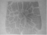
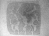
- FIG. 6 is a drawing showing the results of X-ray observation of a bonding layer in a bonding test sample of Example 5. It is drawing which shows the result of the X-ray observation of the joining layer in the joining test sample of Example 6. FIG. It is drawing which shows the result of the SEM observation of the cross section of the joining layer in the joining test sample of Example 6.
- FIG. 6 is a drawing showing the results of X-ray observation of a bonding layer in a bonding test sample of Comparative Example 4.
- 6 is a drawing showing the results of X-ray observation of a bonding layer in a bonding test sample of Comparative Example 5.
- the nickel particle composition of the present invention contains the following components A to C, and the weight ratio of component A and component B (component A: component B) is in the range of 30:70 to 70:30.
- the nickel particles of component A have an average particle diameter in the range of 0.5 to 20 ⁇ m by laser diffraction / scattering method from the viewpoint of suppressing volume shrinkage when forming a bonding layer by heating.
- the average particle diameter of the nickel particles of component A is less than 0.5 ⁇ m, the volume shrinkage increases when the bonding layer is formed by heating, and the objects to be bonded are not sufficiently bonded.
- the average particle diameter of the nickel particles of component A exceeds 20 ⁇ m, the applicability is deteriorated on the bonded body, and the adjustment of the bonding layer thickness becomes difficult.
- the nickel particles of component A may be appropriately selected according to the purpose of use, and the content of nickel element may be appropriately selected.
- the amount of nickel element is preferably 50% by weight or more, more preferably with respect to all metal elements. It is good to set it as 75 weight% or more, More preferably, it is 90 weight% or more.
- the nickel particles of component A most preferably contain 99.0% by weight or more of nickel element.
- the nickel element content of the component A nickel particles is set to 99.0% by weight or more based on the amount of nickel element generally contained in commercially available nickel particles.
- the nickel particles of component A may contain impurity metals in addition to oxygen and carbon as other components other than the nickel element.
- the nickel particles of component A are different from the shell (shell) containing nickel element. It may have a multilayer structure such as a core-shell structure composed of a metal core (center part), or the nickel element concentration in the surface layer part of the nickel particles is higher than the center part, and the concentration of dissimilar metals is in the center part. And may have a high structure.
- the nickel particles of component A are preferably 50% by weight or more, more preferably 75% by weight or more, and still more preferably 90% by weight with respect to all metal elements in the surface layer portion. % Or more is preferable. Therefore, the nickel element concentration can be provided with a gradient so that the surface layer portion of the nickel particles can be highly concentrated, so that the nickel element content can be about 10% by weight with respect to the total metal elements.
- the nickel particles of component A can be used regardless of the production method.
- the nickel particles of component A for example, commercially available products such as those manufactured by Kanto Chemical Co., Ltd. (product name: nickel (powder)) and Sigma-Aldrich Japan LLC (product name: Nickel) can be preferably used.
- the nickel fine particles of component B have an average primary particle diameter in the range of 30 to 200 nm as observed with a scanning electron microscope.
- the average primary particle diameter of the nickel fine particles of component B is preferably in the range of 30 to 100 nm.
- the average primary particle diameter of the nickel fine particles of component B is preferably in the range of 30 to 160 nm.
- the average primary particle size of the nickel fine particles of component B is less than 30 nm, the nickel fine particles are likely to aggregate, and uniform mixing with the nickel particles of component A becomes difficult.
- the average primary particle size of the nickel fine particles of component B exceeds 200 nm, the sintering ability between the nickel fine particles or between the nickel fine particles and the nickel particles of component A is insufficient, leading to a reduction in bonding strength.
- the average particle diameter of the primary particles of the nickel fine particles of component B is determined by a field emission scanning electron microscope (FE-SEM). It is a value calculated by taking a photograph of a sample, randomly extracting 200 samples from the sample, obtaining the area of each sample, and converting the particle size into a true sphere based on the number.
- the nickel fine particles of component B may be appropriately selected according to the purpose of use, and the content of nickel element may be appropriately selected.
- the amount of nickel element is preferably 50% by weight or more, more preferably based on the total metal elements. It may be contained in an amount of 75% by weight or more, more preferably in the range of 90 to 99.0% by weight.
- the average primary particle diameter is within the range of 30 to 200 nm, In the presence of passive oxygen, the content of nickel element becomes the above value.
- the nickel fine particles of the component B are different from the shell (shell portion) containing nickel element from such a viewpoint. It may have a multi-layered structure such as a core-shell structure consisting of a metal core (center part), or the nickel element concentration in the surface layer part of the nickel fine particles is higher than the center part, and the concentration of dissimilar metals is in the center part. And may have a high structure.
- the nickel element is preferably contained in an amount of 50% by weight or more, more preferably 75% by weight or more, and still more preferably 90% by weight or more with respect to all the metal elements in the surface layer portion. . Therefore, the nickel element concentration can be provided with a gradient so that the surface layer portion of the nickel particles can be highly concentrated, so that the nickel element content can be about 10% by weight with respect to the total metal elements.
- the nickel fine particles of component B may contain a metal other than nickel, but the content is most preferably in the range of 1 to 10% by weight.
- metals other than nickel include, for example, base metals such as tin, titanium, cobalt, copper, chromium, manganese, iron, zirconium, tungsten, molybdenum, vanadium, gold, silver, platinum, palladium, iridium, osmium, ruthenium, rhodium, A metal element such as a noble metal such as rhenium can be given. These may be contained alone or in combination of two or more.
- a nonmetallic element such as an oxygen element and a carbon element may be contained.
- the nickel fine particles of component B contain carbon element, the content thereof is, for example, in the range of 0.3 to 2.5% by weight, and preferably in the range of 0.5 to 2.0% by weight.
- the carbon element is derived from an organic compound present on the surface of the nickel fine particles, and contributes to an improvement in the dispersibility of the nickel fine particles.
- the content of the carbon element in the nickel fine particles of component B is less than 0.3% by weight, sufficient dispersibility may not be obtained, and if it exceeds 2.5% by weight, it is carbonized after firing. There is a possibility of remaining charcoal, which may reduce the conductivity of the bonding layer.
- the nickel fine particles of component B contain an oxygen element, the content thereof is, for example, in the range of 0.7 to 7.5% by weight, preferably in the range of 1.0 to 2.0% by weight. is there.
- the nickel fine particles of component B can be used regardless of the production method, but those obtained by a known method in which nickel ions are heated and reduced by a wet reduction method from a mixture containing a nickel salt and an organic amine are preferable. .
- a method for producing nickel fine particles by a wet reduction method will be described.
- the production of nickel fine particles by the wet reduction method includes the following steps 1 and 2; Step 1) A complexing reaction solution generating step of obtaining a complexing reaction solution by heating a mixture containing nickel carboxylate and a primary amine to a temperature within a range of 100 ° C. to 165 ° C., as well as, Step 2) Nickel to obtain a slurry of nickel fine particles coated with primary amine by heating the complexing reaction liquid to a temperature of 170 ° C. or higher by microwave irradiation to reduce nickel ions in the complexing reaction liquid A fine particle slurry generating step.
- the nickel carboxylate (nickel salt of carboxylic acid) is not limited to the type of carboxylic acid.
- the carboxyl group may be a monocarboxylic acid having one carboxyl group, or a carboxylic acid having two or more carboxyl groups. It may be.
- acyclic carboxylic acid may be sufficient and cyclic carboxylic acid may be sufficient.
- a nickel carboxylate acyclic monocarboxylate nickel can be preferably used.
- nickel acyclic monocarboxylates it is more preferable to use, for example, nickel formate, nickel acetate, nickel propionate, nickel oxalate, nickel benzoate and the like.
- nickel acyclic monocarboxylates for example, the resulting nickel fine particles are less likely to have a variation in shape and are easily formed as a uniform shape.
- the nickel carboxylate may be an anhydride or a hydrate.
- the primary amine can form a complex with nickel ions, and effectively exhibits a reducing ability for nickel complexes (or nickel ions).
- secondary amines have great steric hindrance and may hinder the good formation of nickel complexes. Since tertiary amines do not have the ability to reduce nickel ions, none can be used alone. When these are used, these may be used in combination as long as the shape of the nickel fine particles to be produced is not hindered.
- the primary amine is not particularly limited as long as it can form a complex with nickel ions, and can be a solid or liquid at room temperature. Here, room temperature means 20 ° C. ⁇ 15 ° C.
- the primary amine that is liquid at room temperature also functions as an organic solvent for forming the nickel complex.
- it is a primary amine solid at normal temperature, there is no particular problem as long as it is liquid by heating at 100 ° C. or higher, or can be dissolved using an organic solvent.
- the primary amine may be an aromatic primary amine, but an aliphatic primary amine is preferred from the viewpoint of easy nickel complex formation in the reaction solution.
- the aliphatic primary amine can control the particle diameter of the nickel fine particles produced by adjusting the length of the carbon chain, for example, the nickel fine particles having an average primary particle diameter in the range of 30 nm to 200 nm. This is advantageous when manufacturing.
- the aliphatic primary amine is preferably selected from those having about 6 to 20 carbon atoms. The larger the carbon number, the smaller the particle size of the nickel fine particles obtained.
- amines examples include octylamine, trioctylamine, dioctylamine, hexadecylamine, dodecylamine, tetradecylamine, stearylamine, oleylamine, myristylamine, and laurylamine.
- oleylamine exists in a liquid state under the temperature conditions in the nickel fine particle production process, and therefore the reaction can proceed efficiently in a homogeneous solution.
- the primary amine functions as a surface modifier during the production of the nickel fine particles, secondary aggregation can be suppressed even after removal of the primary amine.
- the primary amine is preferably liquid at room temperature from the viewpoint of ease of processing operation in the washing step of separating the solid component of the nickel fine particles produced after the reduction reaction and the solvent or unreacted primary amine.
- the primary amine is preferably one having a boiling point higher than the reduction temperature from the viewpoint of ease of reaction control when the nickel complex is reduced to obtain nickel fine particles. That is, the aliphatic primary amine preferably has a boiling point of 180 ° C. or higher, more preferably 200 ° C. or higher, and preferably has 9 or more carbon atoms.
- the boiling point of C 9 H 21 N (nonylamine) of an aliphatic amine having 9 carbon atoms is 201 ° C.
- the amount of primary amine is preferably 2 mol or more, more preferably 2.2 mol or more, and more preferably 4 mol or more with respect to 1 mol of nickel.
- the upper limit of the amount of primary amine is not particularly limited, but is preferably 20 mol or less from the viewpoint of productivity, for example.
- an organic solvent different from the primary amine may be newly added in order to allow the reaction in the homogeneous solution to proceed more efficiently.
- the organic solvent may be mixed simultaneously with the nickel carboxylate and the primary amine.
- the organic solvent is added after first mixing the nickel carboxylate and the primary amine to form a complex, It is more preferable because it efficiently coordinates to a nickel atom.
- the organic solvent that can be used is not particularly limited as long as it does not inhibit the complex formation between the primary amine and the nickel ion. For example, the organic solvent having 4 to 30 carbon atoms, the organic solvent having 7 to 30 carbon atoms, and the like.
- a saturated or unsaturated hydrocarbon organic solvent, an alcohol organic solvent having 8 to 18 carbon atoms, or the like can be used. Further, from the viewpoint of enabling use even under heating conditions by microwave irradiation, it is preferable to select an organic solvent having a boiling point of 170 ° C. or higher, more preferably in the range of 200 to 300 ° C. It is better to choose one. Specific examples of such an organic solvent include tetraethylene glycol and n-octyl ether.
- the complex formation reaction can proceed even at room temperature, the reaction is carried out by heating to a temperature within the range of 100 ° C. to 165 ° C. in order to perform a sufficient and more efficient complex formation reaction.
- This heating is particularly advantageous when nickel carboxylate hydrate such as nickel formate dihydrate or nickel acetate tetrahydrate is used as nickel carboxylate.
- the heating temperature is preferably a temperature exceeding 100 ° C., more preferably a temperature of 105 ° C. or more, so that the ligand substitution reaction between the coordinating water coordinated with nickel carboxylate and the primary amine is efficient.
- the water molecule as the complex ligand can be dissociated, and the water can be discharged out of the system, so that the complex can be formed efficiently.
- nickel formate dihydrate has a complex structure in which two coordination waters and two formate ions as bidentate ligands exist at room temperature.
- the heat treatment in the complex formation reaction between nickel carboxylate and primary amine is surely separated from the subsequent heat reduction process by microwave irradiation of the nickel complex (or nickel ion) to complete the complex formation reaction.
- the temperature is set to the upper limit temperature or lower, preferably 160 ° C. or lower, more preferably 150 ° C. or lower.
- the heating time can be appropriately determined according to the heating temperature and the content of each raw material, but is preferably 10 minutes or more from the viewpoint of completing the complex formation reaction. There is no upper limit on the heating time, but heat treatment for a long time is useless from the viewpoint of saving energy consumption and process time.
- the heating method is not particularly limited, and may be heating by a heat medium such as an oil bath or heating by microwave irradiation.
- the complex formation reaction between nickel carboxylate and primary amine can be confirmed by a change in the color of the solution when a solution obtained by mixing nickel carboxylate and primary amine in an organic solvent is heated. .
- this complex formation reaction is carried out by measuring the absorption maximum wavelength of the absorption spectrum observed in the wavelength region of 300 nm to 750 nm using, for example, an ultraviolet / visible absorption spectrum measuring apparatus, and measuring the maximum absorption wavelength of the raw material (eg, nickel formate) In dihydrate, the maximum absorption wavelength is 710 nm, and in nickel acetate tetrahydrate, the maximum absorption wavelength is 710 nm.)
- the shift of the complexing reaction solution (the maximum absorption wavelength shifts to 600 nm) is observed. Can be confirmed.
- the resulting reaction solution is heated by microwave irradiation to reduce the nickel ions of the nickel complex as described below.
- the carboxylate ions coordinated in the nuclei are decomposed, and finally nickel fine particles containing nickel having an oxidation number of 0 are generated.
- nickel carboxylate is hardly soluble under conditions other than using water as a solvent, and a solution containing nickel carboxylate needs to be a homogeneous reaction solution as a pre-stage of the heat reduction reaction by microwave irradiation.
- the primary amine used in the present embodiment is liquid under the operating temperature conditions, and is considered to be liquefied by coordination with nickel ions to form a homogeneous reaction solution.
- Step 2) Nickel fine particle slurry generation step:
- the complexing reaction solution obtained by the complexation reaction between nickel carboxylate and primary amine is heated to a temperature of 170 ° C. or higher by microwave irradiation to reduce nickel ions in the complexing reaction solution.
- the temperature for heating by microwave irradiation is preferably 180 ° C. or higher, more preferably 200 ° C. or higher, from the viewpoint of suppressing variation in the shape of the obtained nickel fine particles.
- the upper limit of the heating temperature is not particularly limited, but is preferably set to 270 ° C. or less, for example, from the viewpoint of efficiently performing the treatment.
- the use wavelength of a microwave is not specifically limited, For example, it is 2.45 GHz.
- the heating temperature can be appropriately adjusted by, for example, the type of nickel carboxylate and the use of an additive that promotes the nucleation of nickel fine particles.
- the nickel complex is uniformly and sufficiently generated in the complexing reaction liquid generating step (step in which the nickel complex is generated) in step 1;
- the nickel fine particle slurry generation step it is necessary to simultaneously generate and grow nickel (zero-valent) nuclei generated by reduction of the nickel complex (or nickel ions).
- the heating temperature in the complexing reaction liquid production step within the above specific range and ensuring that it is lower than the microwave heating temperature in the nickel fine particle slurry production step, the particle size and shape are adjusted. Particles are easily generated.
- the heating temperature is too high in the complexing reaction liquid generation step, the formation of nickel complex and the reduction reaction to nickel (zero valence) proceed simultaneously, so that the particles with the uniform particle shape in the nickel fine particle slurry generation step Generation may be difficult.
- the heating temperature of the nickel fine particle slurry generation process is too low, the reduction reaction rate to nickel (zero valence) is slowed and the generation of nuclei is reduced, so that not only the particles are enlarged, but also in terms of the yield of nickel fine particles. Is also not preferred.
- Nickel fine particle slurry obtained by heating by microwave irradiation is, for example, allowed to stand and separated, and after removing the supernatant, washed with an appropriate solvent and dried to obtain nickel fine particles.
- the organic solvent described above may be added as necessary.
- the primary amine used for the complex formation reaction is preferably used as it is as the organic solvent.
- nickel fine particles having an average primary particle diameter in the range of 30 to 200 nm can be prepared.
- Component C Organic binder
- the organic binder of component C has the effect of connecting the nickel particles of component A and the nickel fine particles of component B and placing them in close proximity to make the bonding layer agglomerated. Since the nickel particle composition of the present embodiment includes micrometer-sized particles and nanometer-sized fine particles, due to the difference in particle size, aggregation is less likely to occur compared to uniform particles, and there are few contacts between the particles.
- the organic binder of component C is added thereto, the connection between the particles is formed over a wide range. Then, firing is performed while maintaining a wide range of connection between the nickel particles of component A and the nickel fine particles of component B by the organic binder of component C, thereby obtaining a massive bonding layer having high bonding strength.
- any binder that can be dissolved in an organic solvent can be used without particular limitation.
- thermosetting resins such as phenol resin, epoxy resin, unsaturated polyester resin, urea resin, melamine resin
- thermoplastic resins such as polyethylene resin, acrylic resin, methacrylic resin, nylon resin, acetal resin, and polyvinyl acetal resin.
- a polyvinyl acetal resin is preferable, and a polyvinyl acetal resin having an acetal group unit, an acetyl group unit, and a hydroxyl unit in the molecule is more preferable.
- the organic binder of component C suppresses sedimentation of the nickel particles of component A and the nickel fine particles of component B and maintains a sufficiently dispersed state.
- the molecular weight is preferably 30000 or more, more preferably 100000 or more. preferable.
- organic binder of component C for example, commercially available products such as Sekisui Chemical Co., Ltd. polyvinyl acetal resin (ESREC BH-A; trade name) can be preferably used.
- the weight ratio of component A and component B is in the range of 30:70 to 70:30.
- the ratio of the nickel particles of component A is higher than the above range, the unsintered nickel particles increase, resulting in insufficient strength as a bonding layer.
- the ratio of the nickel particles of component A is lower than the above range, the volume shrinkage of the entire bonding layer increases, and in this case, sufficient bonding strength cannot be obtained.
- the blending amount of the component C organic binder in the nickel particle composition is in the range of 0.1 to 2.5% by weight, preferably 0.3 to 1%, based on the total amount of metals in the composition. It is in the range of 0.5% by weight, more preferably 0.5 to 1.2% by weight.
- total amount of metal means the total weight of the nickel particles of component A and the nickel fine particles of component B.
- the nickel particle composition of the present embodiment includes, as an optional component, for example, a carbon material such as non-spherical nickel having a scale shape or a wire shape, or a carbon nanotube that does not inhibit sintering. Can be included.
- a carbon material such as non-spherical nickel having a scale shape or a wire shape, or a carbon nanotube that does not inhibit sintering. Can be included.
- the bonding material of the present embodiment contains the nickel particle composition.
- the bonding material of the present embodiment can further contain an organic solvent having a boiling point in the range of 100 to 300 ° C.
- the boiling point of the solvent contained in the bonding material is preferably in the range of 150 to 260 ° C. from the viewpoint of practical use. If the boiling point of the organic solvent used is less than 100 ° C, long-term stability tends to be lacking. If the boiling point exceeds 300 ° C, residual carbon is generated in the joining layer without volatilization during heating, and the particles are sintered. And tends to inhibit the formation of intermetallic compounds.
- the joining material is preferably concentrated after adding a high-boiling organic solvent to form a paste.
- the content of the nickel particle composition in the bonding material is, for example, in the range of 70 to 96% by weight, and preferably in the range of 85 to 95% by weight. If the content of the nickel particle composition is less than 70% by weight, the thickness of the bonding layer may be reduced. For example, it may be necessary to repeat coating several times, resulting in unevenness and sufficient bonding strength. It may not be possible. On the other hand, if the content of the nickel particle composition exceeds 96% by weight, the fluidity as a paste is lost, and the usability may be lowered, such as difficulty in coating.
- alcohol-based, aromatic-based, hydrocarbon-based, ester-based, ketone-based and ether-based solvents can be used.
- alcohol solvents include 1-heptanol, 1-octanol, 2-octanol, 2-ethyl-1-hexanol, 1-nonanol, 3,5,5-trimethyl-1-hexanol, 1-decanol, 1-decanol, Aliphatic alcohols having 7 or more carbon atoms such as undecanol, ethylene glycol, diethylene glycol, propylene glycol, trimethylene glycol, 1,2-butanediol, 1,3-butanediol, 1,4-butanediol, tetramethylene glycol, Polyhydric alcohols such as methyl triglycol, terpineols such as ⁇ -terpineol, ⁇ -terpineol
- hydrocarbon solvent examples include octane, nonane, decane, undecane, dodecane, tridecane, tetradecane, and pentadecane.
- 1-undecanol and tetradecane are preferable, and 1-undecanol and / or tetradecane are more preferably included in the range of 15% by weight to 50% by weight with respect to the total organic solvent.
- terpineol it is more preferable to use terpineol in the range of 50% by weight to 85% by weight with respect to the total organic solvent.
- the content of the organic solvent in the bonding material of the present embodiment is, for example, in the range of 4 to 30% by weight, and preferably in the range of 5 to 15% by weight.
- the content of the organic solvent in the bonding material is less than 4% by weight, the fluidity may be lowered and the usability as the bonding material may be reduced.
- the content of the organic solvent exceeds 30% by weight, for example, it becomes necessary to repeat coating several times, which may cause unevenness, and sufficient bonding strength may not be obtained.
- the bonding material of the present embodiment can contain, for example, a thickener, a thixotropic agent, a leveling agent, a surfactant and the like as optional components in addition to the above components.
- the joining material is interposed between the members to be joined in a reducing gas atmosphere containing a reducing gas, for example, within a range of 200 to 400 ° C., preferably 250 to 400.
- a bonding layer is formed between the members to be bonded by heating at a temperature in the range of ° C, more preferably in the range of 250 to 350 ° C.
- the heating temperature for volatilizing or decomposing organic substances present on the surface of the nickel fine particles is, for example, 200 ° C. or higher, preferably 250 ° C.
- the nickel fine particles and the nickel particles are heated.
- the passive layer on the surface of both particles can be removed.
- the heating temperature exceeds 400 ° C., the periphery of the semiconductor device as the bonded member may be damaged.
- a step of applying a paste-like bonding material to one or both bonded surfaces of a pair of bonded members bonding the bonded surfaces together, for example, a temperature of 200
- a step (sintering step) of sintering the bonding material by heating within a range of ⁇ 400 ° C., preferably within a range of 250 ° C. to 400 ° C., more preferably within a range of 250 ° C. to 350 ° C. can be included.
- the coating process for coating the bonding material for example, methods such as spray coating, inkjet coating, and printing can be employed.
- the bonding material can be applied in an arbitrary shape such as a pattern shape, an island shape, a mesh shape, a lattice shape, or a stripe shape according to the purpose.
- the firing step can be performed by pressing the members to be joined at, for example, 10 MPa or less, preferably 1 MPa or less, or more preferably in a non-pressurized state.
- the firing process can be simplified, and further damage due to pressurization of the members to be joined can be reduced.
- the bonding method of the present embodiment can be used, for example, in the bonding of Si or SiC semiconductor materials or in the manufacturing process of electronic components.
- the electronic component mainly include a semiconductor device and an energy conversion module component.
- the electronic component is a semiconductor device, for example, between the back surface of the semiconductor element and the substrate, between the semiconductor electrode and the substrate electrode, between the semiconductor electrode and the semiconductor electrode, between the power device or the power module and the heat dissipation member. It can be applied to joining.
- a contact metal layer made of a material such as Au, Cu, Pd, Ni, Ag, Cr, Ti or an alloy thereof is previously formed on one or both of the surfaces to be bonded.
- a contact metal layer made of a material such as Ti, TiW, TiN, Cr, Ni, Pd, V or an alloy thereof is used. It is preferable to provide it.
- the bonding method of the present embodiment can be used for bonding metal materials.
- the base material deteriorates in the heat-affected zone in joining by wax material or welding, it is preferable to join at a low temperature.
- the joining method of the present embodiment is also suitable for joining, for example, hardened steel, stainless steel, metal materials strengthened by work hardening, inorganic materials and metal materials that deteriorate due to thermal oxidation and thermal strain.
- the joined body include, but are not limited to, a pipe, a plate, a joint, a rod, a wire, and a bolt.
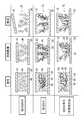
- FIG. 1 schematically shows the state of the bonding site in each of the coating, solvent drying, and firing stages when the member to be bonded 10 and the member to be bonded 20 are bonded by three types of methods including the method of the present invention.
- reference numeral 30 denotes component A nickel particles
- reference numeral 40 denotes component B nickel fine particles
- reference numeral 50 denotes an organic binder of component C
- reference numeral 60 denotes an organic solvent
- reference numeral 70 denotes a bonding layer.
- the upper part of FIG. 1 is a case where a bonding material containing component B nickel fine particles 40 is used, and the middle part is a case where a bonding material containing component B nickel fine particles 40 and component C organic binder 50 is used.
- the lower row shows the case where the bonding material of the present invention containing the nickel particles 30 of component A, the nickel fine particles 40 of component B, and the organic binder 50 of component C is used.
- the particle diameters are uniform in nanometer size, so that they are uniformly dispersed at the time of application.
- the bonding layer 70 is formed based on agglomerates between a small number of adjacent particles based on the aggregating action of the nickel fine particles 40.
- the bonding layer 70 is likely to be broken into fine fragments, and the member 10 to be bonded is easily peeled off.
- the particle diameter is uniform in nanometer size, so that it is uniform during coating. It is in a distributed state.
- the joining layer 70 is formed with the aggregate of the nickel fine particles 40 as a basic unit by the connecting action of the organic binder 50.
- the connection action by the organic binder 50 only strengthens the connection inside the aggregate of the nickel fine particles 40, and the connection between the aggregates is small, so that the bonding layer 70 breaks up into fragments with the aggregate as a unit. It is easy and a sufficiently high bonding strength cannot be obtained.
- the joint layer 70 according to the method of the present invention integrally formed in this way is less likely to be divided and has a very high joint strength as compared with the joint layer 70 having an aggregate (upper stage) or aggregate (middle stage) as a unit. It is done.
- the average particle diameter of the nickel particles used as component A was measured by a laser diffraction / scattering method.
- the apparatus used was LMS-30 manufactured by Seishin Co., Ltd., and the measurement was performed in a flow cell using water as a dispersion medium.
- the average particle size of component B (nickel fine particles) was measured by taking a picture of a sample with a field emission scanning electron microscope (FE-SEM), and randomly taking 200 of them. The respective areas were extracted and the average particle diameter of primary particles was calculated based on the number of particles when converted to a true sphere.
- FE-SEM field emission scanning electron microscope
- the sinterability test sample is fired using a small inert gas oven (trade name: KLO-30NH, manufactured by Koyo Thermo Systems Co., Ltd.) while flowing a mixed gas of 3% hydrogen and 97% nitrogen at a flow rate of 5 L / min.
- the temperature was raised from room temperature to 250 ° C., 300 ° C. or 350 ° C. at a rate of temperature rise of 5 ° C./min, and then the predetermined temperature was maintained for 1 hour. Next, the temperature was lowered to 50 ° C. over 400 minutes, and then left to room temperature.
- no pressure is applied to the sample. That is, firing without pressure.
- shear strength (shear strength) 1] Using a stainless steel mask (mask width; 2.0 mm ⁇ length; 2.0 mm ⁇ thickness; 0.1 mm), the sample was gold-plated copper substrate (width; 10 mm ⁇ length; 10 mm ⁇ thickness; 0 mm) is applied to form a coating film, and then a silicon die (width: 2.0 mm ⁇ length; 2.0 mm ⁇ thickness: 0.40 mm) is mounted on the coating film and firing is performed. went. The shear strength of the obtained joined sample (joint layer thickness; about 50 ⁇ m) was measured with a joint strength tester (manufactured by Daisy Japan, trade name: Bond Tester 4000).
- a bond tester tool was pressed from the side of the die at a height of 50 ⁇ m from the substrate and a tool speed of 100 ⁇ m / second, and the load when the joint was sheared was determined as shear strength (shear strength).
- the gold-plated copper substrate is obtained by plating Ni / Au with a thickness of 4 ⁇ m / 40 to 50 nm on the surface of a Cu substrate (thickness: 1.0 mm), and the silicon die is a Si substrate (thickness). ; 0.40 mm) on the bonding surface, Au was sputtered.
- the nickel fine particle slurry 1 obtained in Synthesis Example 1 was allowed to stand and separated, the supernatant was removed, washed with toluene and methanol, and then dried for 6 hours in a vacuum dryer maintained at 60 ° C. Fine particles 1 (average primary particle size; 92 nm) were obtained.
- Example 1 [Preparation of Paste 1] 125 parts by weight of the slurry solution 1 was collected, and 57 parts by weight of nickel particles 1 (manufactured by Kanto Chemical Co., Ltd., trade name: nickel (powder), average particle diameter by laser diffraction / scattering method); 8 ⁇ m, content of nickel element: 99 wt% or more based on the whole nickel particles), 9.4 parts by weight of ⁇ -terpineol (manufactured by Wako Pure Chemical Industries, Ltd., boiling point: 220 ° C.), 2.0 parts by weight Tetradecane (manufactured by Wako Pure Chemical Industries, Ltd., boiling point: 254 ° C.), 0.78 parts by weight of binder resin 1 (manufactured by Sekisui Chemical Co., Ltd., trade name: ESREC BH-A) were mixed, and 60 ° C. with an evaporator. Concentration was performed at 100 hPa to prepare 126 parts by weight of paste 1 (
- Example 2 [Preparation of paste 2 and evaluation of shear strength] 114 parts by weight of the slurry solution 1 was taken, and 78 parts by weight of nickel particles 1, 10.7 parts by weight of ⁇ -terpineol, 2.3 parts by weight of tetradecane, 0.78 parts by weight of binder resin 1 And concentrated in an evaporator at 60 ° C. and 100 hPa to prepare 170 parts by weight of paste 2 (solid content concentration 91.8% by weight).
- Example 3 [Preparation of paste 3 and evaluation of shear strength] 116 parts by weight of the slurry solution 1 was collected, and 119 parts by weight of nickel particles 1, 13.2 parts by weight of ⁇ -terpineol, 2.9 parts by weight of tetradecane, 1.1 parts by weight of binder resin 1 And concentrated at 60 ° C. and 100 hPa with an evaporator to prepare 215 parts by weight of paste 3 (solid content concentration 92.0% by weight).
- Example 4 [Preparation of paste 4 and evaluation of shear strength] 94.0 parts by weight of slurry solution 1 was fractionated, and 149 parts by weight of nickel particles 1, 13.0 parts by weight of ⁇ -terpineol, 2.7 parts by weight of tetradecane, 1.2 parts by weight of binder Resin 1 was mixed and concentrated by an evaporator at 60 ° C. and 100 hPa to prepare 230 parts by weight of paste 4 (solid content concentration 92.7% by weight).
- the paste 4 was prepared at 350 ° C. in accordance with the above [Baking method 1] and [Shear strength evaluation 1], and the shear strength was evaluated. As a result, a sufficient strength of 8.2 MPa was obtained. The results are shown in Table 1.
- the paste 7 was prepared at 350 ° C. in accordance with the above [Baking method 1] and [Shear strength evaluation 1], and the shear strength was evaluated. As a result, no strength was obtained at 0.0 MPa. The results are shown in Table 1.
- Example 5 ⁇ Preparation of paste 8 and evaluation of shear strength> 167 parts by weight of the slurry solution 1 was collected, and 114 parts by weight of nickel particles, 1,27.0 parts by weight of ⁇ -terpineol, and 1.3 parts by weight of binder resin 1 were mixed, and 60 parts by evaporator. Concentration was conducted at 100 ° C. and 100 hPa to prepare 257 parts by weight of paste 8 (solid content concentration 89.0% by weight).
- Example 6 [Preparation of paste 9 and evaluation of shear strength] 193 parts by weight of the slurry solution 1 was collected, and 131 parts by weight of nickel particles 1, 6.9 parts by weight of ⁇ -terpineol, 6.9 parts by weight of 1-undecanol (manufactured by Wako Pure Chemical Industries, Ltd.) , Boiling point: 220 ° C.), 1.4 parts by weight of binder resin 1 is mixed, and concentrated at 60 ° C. and 100 hPa in an evaporator to prepare 278 parts by weight of paste 9 (solid content concentration 94.5% by weight). did.
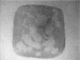
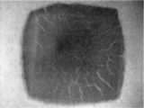
- FIG. 3 shows the result of X-ray observation when the bonding layer in the produced bonding test sample is observed in the direction perpendicular to the bonding surface through the silicon die
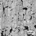
- FIG. 4 shows the result of SEM observation of the cross section of the bonding layer. Indicated.
- Example 7 [Preparation of paste 10 and evaluation of shear strength] 120 parts by weight of the slurry solution 1 was collected, and 81.9 parts by weight of nickel particles 2 (manufactured by Sigma-Aldrich Japan G.K., trade name: Nickel, average particle diameter by laser diffraction / scattering method; 1.9 ⁇ m) Content of nickel element; 99.8% by weight or more based on the whole nickel particles), 13.4 parts by weight of ⁇ -terpineol, 0.9 part by weight of binder resin 1 were mixed, and an evaporator was used at 60 ° C., Concentration was performed at 100 hPa to prepare 178 parts by weight of paste 10 (solid content concentration 92.0% by weight).
- the paste 10 was produced at 300 ° C. in accordance with the above [Baking method 1] and [Shear strength evaluation 1], and the shear strength was evaluated. As a result, a sufficient strength of 10.5 MPa was obtained. The results are shown in Table 2.
- Example 8 [Preparation of paste 11 and evaluation of shear strength] 127 parts by weight of the slurry solution 1 was collected, and 65.0 parts by weight of nickel particles 1, 65.0 parts by weight of nickel particles 2, 5.7 parts by weight of ⁇ -terpineol, 5.7 parts by weight 1-undecanol and 1.2 parts by weight of binder resin 1 were mixed and concentrated by an evaporator at 60 ° C. and 100 hPa to prepare 229 parts by weight of paste 11 (solid content concentration 89.0% by weight).
- the paste 11 was prepared according to the above [Baking method 1] and [Evaluation of shear strength 1] at 300 ° C., and the shear strength was evaluated. As a result, good strength of 32.7 MPa was obtained. The results are shown in Table 2.
- Example 9 [Preparation of paste 12 and evaluation of shear strength] 118 parts by weight of the slurry solution 1 was collected, and 101 parts by weight of nickel particles, 10.0 parts by weight of nickel particles 2, 5.3 parts by weight of ⁇ -terpineol, 5.3 parts by weight of 1 -Undecanol and 1.1 parts by weight of binder resin 1 were mixed and concentrated by an evaporator at 60 ° C and 100 hPa to prepare 213 parts by weight of paste 12 (solid content concentration 94.5% by weight).
- FIG. 5 shows the result of X-ray observation when the bonding layer in the manufactured bonding test sample was observed through the silicon die in the direction perpendicular to the bonding surface.
- the paste 14 was prepared at 300 ° C. in accordance with the above [Baking method 1] and [Shear strength evaluation 1], and the shear strength was evaluated. As a result, a sufficient strength of 2.5 MPa was not obtained.
- Table 2 The results are shown in Table 2. Moreover, the result of the X-ray observation when the bonding layer in the manufactured bonding test sample was observed in a direction perpendicular to the bonding surface through the silicon die is shown in FIG.
- Example 10 [Preparation of paste 16 and evaluation of shear strength] 106 parts by weight of the slurry solution 1 was fractionated into 72.2 parts by weight of nickel particles 2, 3.8 parts by weight of ⁇ -terpineol, 3.8 parts by weight of 1-undecanol, 0.77 parts by weight. The binder resin 1 was mixed and concentrated in an evaporator at 60 ° C. and 100 hPa to prepare 153 parts by weight of paste 16 (solid content concentration 94.5% by weight).
- Example 11 ⁇ Preparation of paste 17 and evaluation of shear strength> 160 parts by weight of the slurry solution 1 was fractionated into 109 parts by weight of nickel particles 1, 6.1 parts by weight of ⁇ -terpineol, 6.1 parts by weight of 1-undecanol, 0.46 parts by weight of binder. Resin 1 was mixed and concentrated in an evaporator at 60 ° C. and 100 hPa to prepare 231 parts by weight of paste 17 (solid content concentration 94.5% by weight).
- the paste 17 was prepared at 300 ° C. in accordance with the above [Baking method 1] and [Shear strength evaluation 1], and the shear strength was evaluated. As a result, a sufficient strength of 13.4 MPa was obtained. The results are shown in Table 3.
- Example 12 ⁇ Preparation of paste 18 and evaluation of shear strength> 179 parts by weight of slurry solution 1 was fractionated into 122 parts by weight of nickel particles 1, 6.6 parts by weight of ⁇ -terpineol, 6.6 parts by weight of 1-undecanol, 2.6 parts by weight of diethylene glycol. (Manufactured by Kanto Chemical Co., Inc., boiling point 244 ° C.) 2.6 parts by weight of the binder resin 1 are mixed, concentrated at 60 ° C. and 100 hPa in an evaporator, and 262 parts by weight of paste 18 (solid content concentration 93.93). 0% by weight) was prepared.
- the paste 18 was prepared at 300 ° C. according to the above [Baking method 1] and [Shear strength evaluation 1], and the shear strength was evaluated. As a result, a good strength of 20.8 MPa was obtained. The results are shown in Table 3.
- Example 13 ⁇ Preparation of paste 19 and evaluation of shear strength> 191 parts by weight of slurry solution 1 was fractionated, and 130 parts by weight of nickel particles, 13.4 parts by weight of ⁇ -terpineol, 23.4 parts by weight of 1-undecanol, and 4.7 parts by weight of binder. Resin 1 was mixed and concentrated in an evaporator at 60 ° C. and 100 hPa to prepare 312 parts by weight of paste 19 (solid content concentration 83.5% by weight).
- Example 14 [Preparation of paste 20] 126 parts by weight of the slurry solution 1 was collected, and 85.8 parts by weight of nickel particles 1, 12.1 parts by weight of ⁇ -terpineol, 2.8 parts by weight of binder resin 2 (BIC Chemie Japan K.K.) Manufactured, trade name: BYK-220S), and concentrated in an evaporator at 60 ° C. and 100 hPa to prepare 186 parts by weight of paste 20 (solid content concentration 92.0% by weight).
- binder resin 2 BIC Chemie Japan K.K.
- the paste 20 was produced at 300 ° C. according to the above [Baking method 1] and [Shear strength evaluation 1], and the shear strength was evaluated. As a result, a sufficient strength of 23.5 MPa was obtained. The results are shown in Table 3.
- the nickel fine particle slurry 2 obtained in Synthesis Example 2 was left standing and separated, the supernatant was removed, washed with toluene and methanol, and then dried for 6 hours in a vacuum dryer maintained at 60 ° C. Fine particles 2 (average primary particle size; 119 nm) were obtained.
- slurry solution 2 100 parts by weight of the nickel fine particle slurry 2 obtained in Synthesis Example 2 was taken, 20 parts by weight of octanoic acid was added thereto, stirred for 15 minutes, and then washed with toluene to obtain slurry solution 2 (solid content concentration 70.9). % By weight) was prepared.
- the nickel fine particle slurry 3 obtained in Synthesis Example 3 was allowed to stand and separated, the supernatant was removed, washed with toluene and methanol, and then dried for 6 hours in a vacuum dryer maintained at 60 ° C. Fine particles 3 (average primary particle size; 40 nm) were obtained.
- slurry solution 3 100 parts by weight of the nickel fine particle slurry 3 obtained in Synthesis Example 3 was taken, 20 parts by weight of octanoic acid was added thereto, stirred for 15 minutes, and then washed with toluene to obtain slurry solution 3 (solid content concentration 67.3). % By weight) was prepared.
- Example 15 [Preparation of paste 22 and evaluation of shear strength] 141 parts by weight of the slurry solution 2 was collected, and 100 parts by weight of nickel particles 1, 5.3 parts by weight of ⁇ -terpineol, 5.3 parts by weight of 1-undecanol, 1.1 parts by weight of binder Resin 1 was mixed and concentrated in an evaporator at 60 ° C. and 100 hPa to prepare 212 parts by weight of paste 22 (solid content concentration 94.5% by weight).
- the paste 22 was prepared according to the above [Baking method 1] and [Evaluation of shear strength 1] at 300 ° C., and the shear strength was evaluated. As a result, a good strength of 26.4 MPa was obtained. The results are shown in Table 4.
- Example 16 [Preparation of paste 23 and evaluation of shear strength] 202 parts by weight of the slurry solution 3 was taken, and 136 parts by weight of nickel particles 1, 7.2 parts by weight of ⁇ -terpineol, 7.2 parts by weight of 1-undecanol, 1.5 parts by weight of binder Resin 1 was mixed and concentrated in an evaporator at 60 ° C. and 100 hPa to prepare 288 parts by weight of paste 23 (solid content concentration 94.5% by weight).
Landscapes
- Engineering & Computer Science (AREA)
- Mechanical Engineering (AREA)
- Physics & Mathematics (AREA)
- Chemical & Material Sciences (AREA)
- Dispersion Chemistry (AREA)
- Spectroscopy & Molecular Physics (AREA)
- Powder Metallurgy (AREA)
- Manufacture Of Metal Powder And Suspensions Thereof (AREA)
Abstract
Description
A)レーザー回折/散乱法による平均粒子径が0.5~20μmの範囲内であり、ニッケル元素を50重量%以上含有するニッケル粒子、
B)走査型電子顕微鏡観察による平均一次粒子径が30~200nmの範囲内であり、ニッケル元素を50重量%以上含有するニッケル微粒子、
C)全金属量に対して0.1~2.5重量%の範囲内の有機バインダー、
を含有し、
前記成分A及び成分Bの重量比(成分A:成分B)が30:70~70:30の範囲内である。
本発明のニッケル粒子組成物は、次の成分A~Cを含有し、成分A及び成分Bの重量比(成分A:成分B)が30:70~70:30の範囲内である。
A)レーザー回折/散乱法による平均粒子径が0.5~20μmの範囲内であり、ニッケル元素を50重量%以上含有するニッケル粒子、
B)走査型電子顕微鏡観察による平均一次粒子径が30~200nmの範囲内であり、ニッケル元素を50重量%以上含有するニッケル微粒子、
及び、
C)全金属量に対して0.1~2.5重量%の範囲内の有機バインダー。
成分Aのニッケル粒子は、加熱よる接合層形成時の体積収縮を抑制する観点から、レーザー回折/散乱法による平均粒子径が0.5~20μmの範囲内とする。成分Aのニッケル粒子の平均粒子径が0.5μm未満であると、加熱による接合層形成時において体積収縮が大きくなり、被接合体同士が十分に接合しない。一方、成分Aのニッケル粒子の平均粒子径が20μmを超えると、被接合体上に塗布性の悪化や、接合層厚みの調整が困難となる。
成分Bのニッケル微粒子は、走査型電子顕微鏡観察による平均一次粒子径が30~200nmの範囲内である。例えば、本発明のニッケル粒子組成物を300℃の温度で加熱して焼結させる場合は、成分Bのニッケル微粒子の平均一次粒子径は30~100nmの範囲内であることが好ましい。また、本発明のニッケル粒子組成物を350℃の温度で加熱して焼結させる場合は、成分Bのニッケル微粒子の平均一次粒子径は30~160nmの範囲内であることが好ましい。成分Bのニッケル微粒子の平均一次粒子径が30nm未満であると、ニッケル微粒子が凝集しやすくなり、成分Aのニッケル粒子との均一な混合が困難となる。一方、成分Bのニッケル微粒子の平均一次粒子径が200nmを超えると、ニッケル微粒子間もしくはニッケル微粒子と成分Aのニッケル粒子との焼結能力が不十分であり、接合強度の低下を招く。なお、本明細書において、成分Bのニッケル微粒子の一次粒子の平均粒子径は、実施例で用いた値を含めて、電界放出形走査電子顕微鏡(Field Emission-Scanning Electron Microscope:FE-SEM)により試料の写真を撮影して、その中から無作為に200個を抽出してそれぞれの面積を求め、真球に換算したときの粒子径を個数基準として算出した値である。
工程1)カルボン酸ニッケル及び1級アミンを含む混合物を、100℃~165℃の範囲内の温度に加熱して錯化反応液を得る錯化反応液生成工程、
及び、
工程2)該錯化反応液を、マイクロ波照射によって170℃以上の温度に加熱して該錯化反応液中のニッケルイオンを還元し、1級アミンで被覆されたニッケル微粒子のスラリーを得るニッケル微粒子スラリー生成工程、を含むことができる。
(カルボン酸ニッケル)
カルボン酸ニッケル(カルボン酸のニッケル塩)は、カルボン酸の種類を限定するものではなく、例えば、カルボキシル基が1つのモノカルボン酸であってもよく、また、カルボキシル基が2つ以上のカルボン酸であってもよい。また、非環式カルボン酸であってもよく、環式カルボン酸であってもよい。このようなカルボン酸ニッケルとして、非環式モノカルボン酸ニッケルを好適に用いることができる。非環式モノカルボン酸ニッケルのなかでも、例えばギ酸ニッケル、酢酸ニッケル、プロピオン酸ニッケル、シュウ酸ニッケル、安息香酸ニッケル等を用いることがより好ましい。これらの非環式モノカルボン酸ニッケルを用いることによって、例えば、得られるニッケル微粒子は、その形状のばらつきが抑制され、均一な形状として形成されやすくなる。カルボン酸ニッケルは、無水物であってもよく、また水和物であってもよい。
1級アミンは、ニッケルイオンとの錯体を形成することができ、ニッケル錯体(又はニッケルイオン)に対する還元能を効果的に発揮する。一方、2級アミンは立体障害が大きいため、ニッケル錯体の良好な形成を阻害するおそれがあり、3級アミンはニッケルイオンの還元能を有しないため、いずれも単独では使用できないが、1級アミンを使用する上で、生成するニッケル微粒子の形状に支障を与えない範囲でこれらを併用することは差し支えない。1級アミンは、ニッケルイオンとの錯体を形成できるものであれば、特に限定するものではなく、常温で固体又は液体のものが使用できる。ここで、常温とは、20℃±15℃をいう。常温で液体の1級アミンは、ニッケル錯体を形成する際の有機溶媒としても機能する。なお、常温で固体の1級アミンであっても、100℃以上の加熱によって液体であるか、又は有機溶媒を用いて溶解するものであれば、特に問題はない。
工程1では、均一溶液での反応をより効率的に進行させるために、1級アミンとは別の有機溶媒を新たに添加してもよい。有機溶媒を用いる場合、有機溶媒をカルボン酸ニッケル及び1級アミンと同時に混合してもよいが、カルボン酸ニッケル及び1級アミンを先ず混合し錯形成した後に有機溶媒を加えると、1級アミンが効率的にニッケル原子に配位するので、より好ましい。使用できる有機溶媒としては、1級アミンとニッケルイオンとの錯形成を阻害しないものであれば、特に限定するものではなく、例えば炭素数4~30のエーテル系有機溶媒、炭素数7~30の飽和又は不飽和の炭化水素系有機溶媒、炭素数8~18のアルコール系有機溶媒等を使用することができる。また、マイクロ波照射による加熱条件下でも使用を可能とする観点から、使用する有機溶媒は、沸点が170℃以上のものを選択することが好ましく、より好ましくは200~300℃の範囲内にあるものを選択することがよい。このような有機溶媒の具体例としては、例えばテトラエチレングリコール、n-オクチルエーテル等が挙げられる。
本工程では、カルボン酸ニッケルと1級アミンとの錯形成反応によって得られた錯化反応液を、マイクロ波照射によって170℃以上の温度に加熱し、錯化反応液中のニッケルイオンを還元して1級アミンで被覆されたニッケル微粒子スラリーを得る。マイクロ波照射によって加熱する温度は、得られるニッケル微粒子の形状のばらつきを抑制するという観点から、好ましくは180℃以上、より好ましくは200℃以上とすることがよい。加熱温度の上限は特にないが、処理を能率的に行う観点からは例えば270℃以下とすることが好適である。なお、マイクロ波の使用波長は、特に限定するものではなく、例えば2.45GHzである。また、加熱温度は、例えばカルボン酸ニッケルの種類やニッケル微粒子の核発生を促進させる添加剤の使用などによって、適宜調整することができる。
成分Cの有機バインダーは、成分Aのニッケル粒子と成分Bのニッケル微粒子とを連結させ、両者を近接した状態に置くことによって、接合層を塊状にする作用を有する。本実施の形態のニッケル粒子組成物では、マイクロメートルサイズの粒子とナノメートルサイズの微粒子を含むことから、粒子サイズの相違によって、均一粒子に比べて凝集が生じにくく、粒子どうしの接点が少ない。そこに成分Cの有機バインダーを添加すると、粒子どうしの連結が広範囲にわたって形成される。そして、成分Cの有機バインダーによって成分Aのニッケル粒子と成分Bのニッケル微粒子との広範囲の連結状態を維持したまま、焼成を行うことによって、高い接合強度を有する塊状の接合層が得られる。
ニッケル粒子組成物は、成分A及び成分Bの重量比(成分A:成分B)が30:70~70:30の範囲内である。上記範囲よりも成分Aのニッケル粒子の割合が高くなると、焼結されていないニッケル粒子が増えることにより、接合層としての強度不足が生じる。一方、上記範囲よりも成分Aのニッケル粒子の割合が低くなると、接合層全体の体積収縮が大きくなり、この場合もまた十分な接合強度が得られない。
本実施の形態の接合材は、上記ニッケル粒子組成物を含有する。本実施の形態の接合材は、さらに、沸点100~300℃の範囲内にある有機溶媒を含有することができる。接合材に含有される溶媒の沸点は、実使用上の観点から、150~260℃の範囲内が好ましい。使用する有機溶媒の沸点が100℃未満であると、長期安定性に欠ける傾向があり、300℃を超えると、加熱時に揮発せずに、接合層中に残炭が生じ、粒子同士の焼結や金属間化合物の形成を阻害する傾向がある。接合材は、高沸点の有機溶媒を添加後、濃縮し、ペーストの形態とすることが好ましい。
本実施の形態の接合方法は、上記接合材を、被接合部材の間に介在させて還元性ガスを含有する還元性ガス雰囲気下で、例えば200~400℃の範囲内、好ましくは250~400℃の範囲内、より好ましくは250~350℃の範囲内の温度で加熱することにより、被接合部材の間に接合層を形成する。ニッケル微粒子どうし、ニッケル微粒子とニッケル粒子との間に焼結を進行させるためには、ニッケル微粒子およびニッケル粒子の金属表面を露出させることが必要であると考えられる。ニッケル微粒子表面に存在する有機物を揮発又は分解させる加熱温度は、例えば200℃以上であり、250℃以上が好ましく、さらには、還元性ガス雰囲気下で加熱を行うことにより、ニッケル微粒子、ニッケル粒子の両粒子表面の不動態層を除去することができる。一方、加熱温度が400℃を超えると、被接合部材としての半導体デバイス周辺にダメージを与える場合がある。
次に、図1を参照しながら、本発明の作用について説明する。図1は、本発明方法を含む3種類の方法で被接合部材10と被接合部材20とを接合する場合の塗布、溶剤乾燥、焼成の各ステージにおける接合部位の状態を模式的に示している。図1において、符号30は成分Aのニッケル粒子、符号40は成分Bのニッケル微粒子、符号50は成分Cの有機バインダー、符号60は有機溶媒、符号70は接合層を意味する。
成分Aとして使用されるニッケル粒子の平均粒子径の測定は、レーザー回折/散乱法によって行った。装置は株式会社セイシン企業製LMS-30を用い、水を分散媒としてフローセル中で測定した。
成分B(ニッケル微粒子)の平均粒子径の測定は、電界放出形走査電子顕微鏡(Field Emission-Scanning Electron Microscope:FE-SEM)により試料の写真を撮影して、その中から無作為に200個を抽出してそれぞれの面積を求め、真球に換算したときの粒子径を個数基準として一次粒子の平均粒子径を算出した。
焼結性試験用サンプルの焼成は、小型イナートガスオーブン(光洋サーモシステム社製、商品名;KLO-30NH)を使用し、3%水素及び97%窒素の混合ガスを流量5L/分でフローしながら、昇温速度5℃/分で、常温から250℃、300℃又は350℃まで昇温した後、1時間所定温度を保持した。次いで、400分間かけて50℃まで降温した後、常温まで放置した。なお、焼結性試験用サンプルの焼成においては、サンプルへの加圧は行っていない。すなわち、無加圧での焼成である。
ステンレス製マスク(マスク幅;2.0mm×長さ;2.0mm×厚さ;0.1mm)を用いて、試料を金めっき銅基板(幅;10mm×長さ;10mm×厚さ;1.0mm)上に塗布して塗布膜を形成した後、その塗布膜の上に、シリコンダイ(幅;2.0mm×長さ;2.0mm×厚さ;0.40mm)を搭載し、焼成を行った。得られた接合サンプル(接合層の厚さ;50μm程度)を接合強度試験機(デイジ・ジャパン社製、商品名;ボンドテスター4000)により、せん断強度を測定した。ダイ側面からボンドテスターツールを、基板からの高さ50μm、ツール速度100μm/秒で押圧し、接合部がせん断破壊したときの荷重をせん断強度(シェア強度)とした。なお、金めっき銅基板は、Cu基板(厚さ;1.0mm)の表面に、Ni/Auをそれぞれ4μm/40~50nmの厚みでめっきしたものであり、シリコンダイは、Si基板(厚さ;0.40mm)の接合面に、Auをスパッタしたものである。
上記せん断強度評価1と同様に作製した接合サンプルを、エポキシ樹脂により包埋後、断面加工を施し、電界放出形走査電子顕微鏡(FE-SEM)にて観察した。
642重量部のオレイルアミンに100.1重量部の酢酸ニッケル四水和物を加え、窒素フロー下、150℃で20分加熱することによって酢酸ニッケルを溶解させて錯化反応液を得た。次いで、その錯化反応液に、492重量部のオレイルアミンを加え、マイクロ波を用いて250℃で5分加熱することによって、ニッケル微粒子スラリー1を得た。
合成例1で得られたニッケル微粒子スラリー1を100重量部分取し、これに20重量部のオクタン酸を加え、15分間撹拌した後、トルエンで洗浄し、スラリー溶液1(固形分濃度68.1重量%)を調製した。
[ペースト1の調製]
スラリー溶液1の125重量部を分取し、これに、57重量部のニッケル粒子1(関東化学工業株式会社製、商品名;ニッケル(粉末)、レーザー回折/散乱法による平均粒子径;9.8μm、ニッケル元素の含有量;ニッケル粒子全体に対して99重量%以上)、9.4重量部のα-テルピネオール(和光純薬工業株式会社製、沸点;220℃)、2.0重量部のテトラデカン(和光純薬工業株式会社製、沸点254℃)、0.78重量部のバインダー樹脂1(積水化学工業株式会社製、商品名;エスレックBH-A)を混合し、エバポレータにて60℃、100hPaで濃縮を行い、126重量部のペースト1(固形分濃度92.1重量%)を調製した。
[ペースト2の調製とせん断強度評価]
スラリー溶液1の114重量部を分取し、これに、78重量部のニッケル粒子1、10.7重量部のα-テルピネオール、2.3重量部のテトラデカン、0.78重量部のバインダー樹脂1を混合し、エバポレータにて60℃、100hPaで濃縮を行い、170重量部のペースト2(固形分濃度91.8重量%)を調製した。
[ペースト3の調製とせん断強度評価]
スラリー溶液1の116重量部を分取し、これに、119重量部のニッケル粒子1、13.2重量部のα-テルピネオール、2.9重量部のテトラデカン、1.1重量部のバインダー樹脂1を混合し、エバポレータにて60℃、100hPaで濃縮を行い、215重量部のペースト3(固形分濃度92.0重量%)を調製した。
[ペースト4の調製とせん断強度評価]
スラリー溶液1の94.0重量部を分取し、これに、149重量部のニッケル粒子1、13.0重量部のα-テルピネオール、2.7重量部のテトラデカン、1.2重量部のバインダー樹脂1を混合し、エバポレータにて60℃、100hPaで濃縮を行い、230重量部のペースト4(固形分濃度92.7重量%)を調製した。
[ペースト5の調製とせん断強度評価]
スラリー溶液1の229重量部を分取し、これに、26.8重量部のα-テルピネオール、5.8重量部のテトラデカン、1.9重量部のバインダー樹脂1を混合し、エバポレータにて60℃、100hPaで濃縮を行い、190重量部のペースト5(固形分濃度81.9重量%)を調製した。
[ペースト6の調製とせん断強度評価]
スラリー溶液1の134重量部を分取し、これに、23重量部のニッケル粒子1、8.9重量部のα-テルピネオール、1.9重量部のテトラデカン、0.63重量部のバインダー樹脂1を混合し、エバポレータにて60℃、100hPaで濃縮を行い、126重量部のペースト6(固形分濃度91.0重量%)を調製した。
[ペースト7の調製とせん断強度評価]
スラリー溶液1の92.1重量部を分取し、これに、251重量部のニッケル粒子1、18.3重量部のα-テルピネオール、3.8重量部のテトラデカン、1.7重量部のバインダー樹脂1を混合し、エバポレータにて60℃、100hPaで濃縮を行い、337重量部のペースト7(固形分濃度93.0重量%)を調製した。

<ペースト8の調製とせん断強度評価>
スラリー溶液1の167重量部を分取し、これに、114重量部のニッケル粒子1、27.0重量部のα-テルピネオール、1.3重量部のバインダー樹脂1を混合し、エバポレータにて60℃、100hPaで濃縮を行い、257重量部のペースト8(固形分濃度89.0重量%)を調製した。
[ペースト9の調製とせん断強度評価]
スラリー溶液1の193重量部を分取し、これに、131重量部のニッケル粒子1、6.9重量部のα-テルピネオール、6.9重量部の1-ウンデカノール(和光純薬工業株式会社製、沸点;220℃)、1.4重量部のバインダー樹脂1を混合し、エバポレータにて60℃、100hPaで濃縮を行い、278重量部のペースト9(固形分濃度94.5重量%)を調製した。
[ペースト10の調製とせん断強度評価]
スラリー溶液1の120重量部を分取し、これに、81.9重量部のニッケル粒子2(シグマアルドリッチジャパン合同会社製、商品名;Nickel、レーザー回折/散乱法による平均粒子径;1.9μm、ニッケル元素の含有量;ニッケル粒子全体に対して99.8重量%以上)、13.4重量部のα-テルピネオール、0.9重量部のバインダー樹脂1を混合し、エバポレータにて60℃、100hPaで濃縮を行い、178重量部のペースト10(固形分濃度92.0重量%)を調製した。
[ペースト11の調製とせん断強度評価]
スラリー溶液1の127重量部を分取し、これに、65.0重量部のニッケル粒子1、65.0重量部のニッケル粒子2、5.7重量部のα-テルピネオール、5.7重量部の1-ウンデカノール、1.2重量部のバインダー樹脂1を混合し、エバポレータにて60℃、100hPaで濃縮を行い、229重量部のペースト11(固形分濃度89.0重量%)を調製した。
[ペースト12の調製とせん断強度評価]
スラリー溶液1の118重量部を分取し、これに、101重量部のニッケル粒子1、20.0重量部のニッケル粒子2、5.3重量部のα-テルピネオール、5.3重量部の1-ウンデカノール、1.1重量部のバインダー樹脂1を混合し、エバポレータにて60℃、100hPaで濃縮を行い、213重量部のペースト12(固形分濃度94.5重量%)を調製した。
[ペースト13の調製]
スラリー溶液1の151重量部を分取し、これに、12.8重量部のα-テルピネオール、を混合し、エバポレータにて60℃、100hPaで濃縮を行い、126重量部のペースト13(固形分濃度88.9重量%)を調製した。
[ペースト14の調製]
スラリー溶液1の163重量部を分取し、これに、13.2重量部のα-テルピネオール、2.0重量部の1-ウンデカノール、0.63重量部のバインダー樹脂1を混合し、エバポレータにて60℃、100hPaで濃縮を行い、126重量部のペースト14(固形分濃度92.1重量%)を調製した。
[ペースト15の調製]
スラリー溶液1の121重量部を分取し、これに、82.5重量部のニッケル粒子1、4.8重量部のα-テルピネオール、4.8重量部の1-ウンデカノールを混合し、エバポレータにて60℃、100hPaで濃縮を行い、175重量部のペースト15(固形分濃度94.5重量%)を調製した。
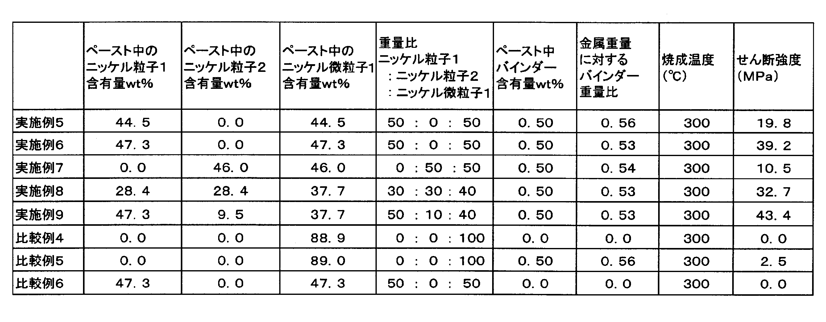
[ペースト16の調製とせん断強度評価]
スラリー溶液1の106重量部を分取し、これに、72.2重量部のニッケル粒子2、3.8重量部のα-テルピネオール、3.8重量部の1-ウンデカノール、0.77重量部のバインダー樹脂1を混合し、エバポレータにて60℃、100hPaで濃縮を行い、153重量部のペースト16(固形分濃度94.5重量%)を調製した。
<ペースト17の調製とせん断強度評価>
スラリー溶液1の160重量部を分取し、これに、109重量部のニッケル粒子1、6.1重量部のα-テルピネオール、6.1重量部の1-ウンデカノール、0.46重量部のバインダー樹脂1を混合し、エバポレータにて60℃、100hPaで濃縮を行い、231重量部のペースト17(固形分濃度94.5重量%)を調製した。
<ペースト18の調製とせん断強度評価>
スラリー溶液1の179重量部を分取し、これに、122重量部のニッケル粒子1、6.6重量部のα-テルピネオール、6.6重量部の1-ウンデカノール、2.6重量部のジエチレングリコール(関東化学工業株式会社製、沸点244℃)、2.6重量部のバインダー樹脂1を混合し、エバポレータにて60℃、100hPaで濃縮を行い、262重量部のペースト18(固形分濃度93.0重量%)を調製した。
<ペースト19の調製とせん断強度評価>
スラリー溶液1の191重量部を分取し、これに、130重量部のニッケル粒子1、23.4重量部のα-テルピネオール、23.4重量部の1-ウンデカノール、4.7重量部のバインダー樹脂1を混合し、エバポレータにて60℃、100hPaで濃縮を行い、312重量部のペースト19(固形分濃度83.5重量%)を調製した。
[ペースト20の調製]
スラリー溶液1の126重量部を分取し、これに、85.8重量部のニッケル粒子1、12.1重量部のα-テルピネオール、2.8重量部のバインダー樹脂2(ビックケミー・ジャパン株式会社製、商品名;BYK-220S)を混合し、エバポレータにて60℃、100hPaで濃縮を行い、186重量部のペースト20(固形分濃度92.0重量%)を調製した。
[ペースト21の調製]
スラリー溶液1の169重量部を分取し、これに、115重量部のニッケル粒子1、39.7重量部のα-テルピネオール、39.7重量部の1-ウンデカノール、7.9重量部のバインダー樹脂1を混合し、エバポレータにて60℃、100hPaで濃縮を行い、317重量部のペースト21(固形分濃度72.5重量%)を調製した。
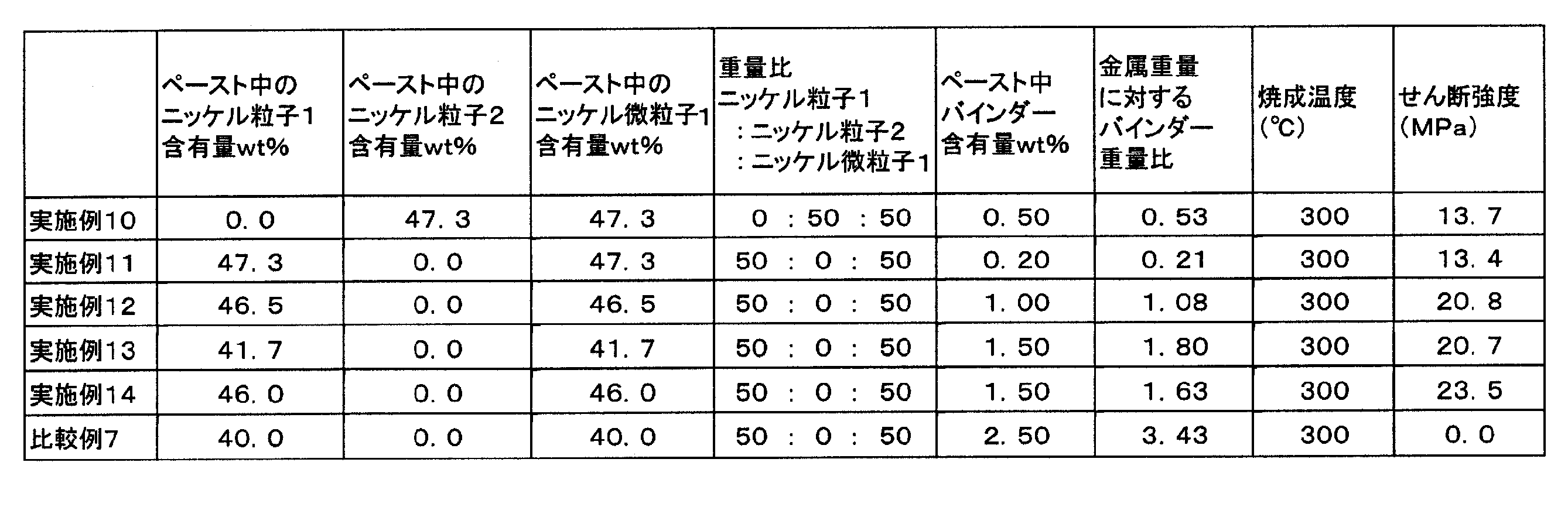
211重量部のオレイルアミンに33重量部の酢酸ニッケル四水和物を加え、窒素フロー下、150℃で20分加熱することによって酢酸ニッケルを溶解させて錯化反応液を得た。次いで、その錯化反応液に、100重量部のオレイルアミンを加え、マイクロ波を用いて250℃で5分加熱することによって、ニッケル微粒子スラリー2を得た。
合成例2で得られたニッケル微粒子スラリー2を100重量部分取し、これに20重量部のオクタン酸を加え、15分間撹拌した後、トルエンで洗浄し、スラリー溶液2(固形分濃度70.9重量%)を調製した。
182重量部のオレイルアミンに18.5重量部のギ酸ニッケル二水和物を加え、窒素フロー下、120℃で10分間加熱することによって、ギ酸ニッケルを溶解させて錯化反応液を得た。次いで、その錯化反応液に、121重量部のオレイルアミンを加え、マイクロ波を用いて180℃で10分間加熱することによって、ニッケル微粒子スラリー3を得た。
合成例3で得られたニッケル微粒子スラリー3を100重量部分取し、これに20重量部のオクタン酸を加え、15分間撹拌した後、トルエンで洗浄し、スラリー溶液3(固形分濃度67.3重量%)を調製した。
[ペースト22の調製とせん断強度評価]
スラリー溶液2の141重量部を分取し、これに、100重量部のニッケル粒子1、5.3重量部のα-テルピネオール、5.3重量部の1-ウンデカノール、1.1重量部のバインダー樹脂1を混合し、エバポレータにて60℃、100hPaで濃縮を行い、212重量部のペースト22(固形分濃度94.5重量%)を調製した。
[ペースト23の調製とせん断強度評価]
スラリー溶液3の202重量部を分取し、これに、136重量部のニッケル粒子1、7.2重量部のα-テルピネオール、7.2重量部の1-ウンデカノール、1.5重量部のバインダー樹脂1を混合し、エバポレータにて60℃、100hPaで濃縮を行い、288重量部のペースト23(固形分濃度94.5重量%)を調製した。
[ペースト23のせん断強度評価]
ペースト23を上記[焼成方法1]、[せん断強度の評価1]に従い、接合試験サンプルを250℃で作製し、せん断強度を評価した結果、13.7MPaと十分な強度が得られた。結果を表4に示す。
[ペースト9のせん断強度評価]
ペースト9を上記[焼成方法1]、[せん断強度の評価1]に従い、接合試験サンプルを250℃で作製し、せん断強度を評価した結果、19.2MPaと良好な強度が得られた。結果を表4に示す。
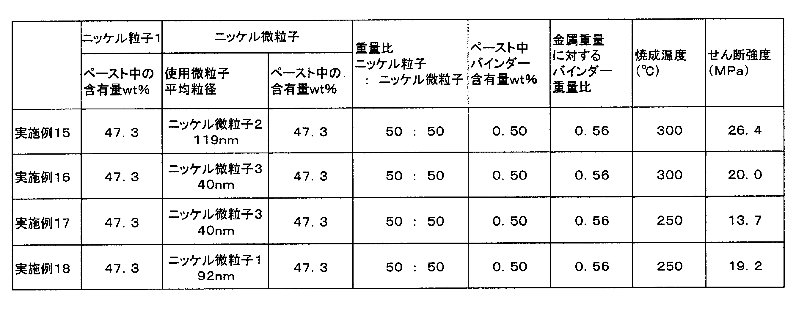
Claims (10)
- 次の成分A~C;
A)レーザー回折/散乱法による平均粒子径が0.5~20μmの範囲内であり、ニッケル元素を50重量%以上含有するニッケル粒子、
B)走査型電子顕微鏡観察による平均一次粒子径が30~200nmの範囲内であり、ニッケル元素を50重量%以上含有するニッケル微粒子、
C)全金属量に対して0.1~2.5重量%の範囲内の有機バインダー、
を含有し、
前記成分A及び成分Bの重量比(成分A:成分B)が30:70~70:30の範囲内であるニッケル粒子組成物。 - 前記成分Aのニッケル元素の含有量が99.0重量%以上である請求項1に記載のニッケル粒子組成物。
- 前記成分Bのニッケル元素の含有量が90~99.0重量%の範囲内である請求項1又は2に記載のニッケル粒子組成物。
- 前記成分Aのニッケル元素の含有量が99.0重量%以上、前記成分Bのニッケル元素の含有量が90~99.0重量%の範囲内である請求項1に記載のニッケル粒子組成物。
- 前記成分Aのニッケル元素の含有量が99.0重量%以上、前記成分Bのニッケル元素の含有量が90~99.0重量%の範囲内、前記成分Cの含有量が全金属量に対して0.1~2.5重量%の範囲内である請求項1に記載のニッケル粒子組成物。
- 前記成分Aのニッケル元素の含有量が99.0重量%以上、前記成分Bのニッケル元素の含有量が90~99.0重量%の範囲内、前記成分Cの含有量が全金属量に対して0.3~1.5重量%の範囲内である請求項1に記載のニッケル粒子組成物。
- 請求項1~6のいずれか1項に記載のニッケル粒子組成物を含有する接合材であって、前記ニッケル粒子組成物の含有量が70~96重量%の範囲内である接合材。
- さらに、沸点100~300℃の範囲内にある有機溶媒を含有し、前記有機溶媒の含有量が4~30重量%の範囲内である請求項7に記載の接合材。
- 前記有機溶媒が1-ウンデカノール及びテトラデカンからなる群より選ばれる少なくとも1種を全有機溶媒に対して15重量%~50重量%の範囲内で含む請求項8記載の接合材。
- 請求項7~9のいずれか1項に記載の接合材を、被接合部材の間に介在させて還元性ガスを含有する還元性ガス雰囲気下で200~400℃の範囲内の温度で加熱することにより、被接合部材の間に接合層を形成する接合方法。
Priority Applications (3)
| Application Number | Priority Date | Filing Date | Title |
|---|---|---|---|
| JP2016531371A JP6734775B2 (ja) | 2014-06-30 | 2015-06-30 | ニッケル粒子組成物、接合材及びそれを用いた接合方法 |
| EP15815115.9A EP3162467B1 (en) | 2014-06-30 | 2015-06-30 | Nickel particle composition, bonding material, and bonding method in which said material is used |
| US15/323,092 US10207373B2 (en) | 2014-06-30 | 2015-06-30 | Nickel particle composition, bonding material, and bonding method in which said material is used |
Applications Claiming Priority (2)
| Application Number | Priority Date | Filing Date | Title |
|---|---|---|---|
| JP2014135245 | 2014-06-30 | ||
| JP2014-135245 | 2014-06-30 |
Publications (1)
| Publication Number | Publication Date |
|---|---|
| WO2016002741A1 true WO2016002741A1 (ja) | 2016-01-07 |
Family
ID=55019273
Family Applications (1)
| Application Number | Title | Priority Date | Filing Date |
|---|---|---|---|
| PCT/JP2015/068757 Ceased WO2016002741A1 (ja) | 2014-06-30 | 2015-06-30 | ニッケル粒子組成物、接合材及びそれを用いた接合方法 |
Country Status (5)
| Country | Link |
|---|---|
| US (1) | US10207373B2 (ja) |
| EP (1) | EP3162467B1 (ja) |
| JP (1) | JP6734775B2 (ja) |
| TW (1) | TWI652353B (ja) |
| WO (1) | WO2016002741A1 (ja) |
Cited By (4)
| Publication number | Priority date | Publication date | Assignee | Title |
|---|---|---|---|---|
| JP2018172792A (ja) * | 2017-03-31 | 2018-11-08 | 新日鉄住金化学株式会社 | ニッケル微粒子組成物、接合構造体及び接合方法 |
| CN109153036A (zh) * | 2016-05-13 | 2019-01-04 | 纳诺克技术公司 | 用于增材制造的可烧结金属浆料 |
| CN109475983A (zh) * | 2016-08-02 | 2019-03-15 | 株式会社弘辉 | 焊膏用助焊剂和焊膏 |
| US11810885B2 (en) * | 2018-08-31 | 2023-11-07 | Waseda University | Semiconductor element bonding structure, method for producing semiconductor element bonding structure, and electrically conductive bonding agent |
Families Citing this family (5)
| Publication number | Priority date | Publication date | Assignee | Title |
|---|---|---|---|---|
| DE102021110298A1 (de) * | 2021-04-22 | 2022-10-27 | Infineon Technologies Ag | Bleifreies lotmaterial, schichtstruktur, verfahren zur herstellung eines lotmaterials und verfahren zur herstellung einer schichtstruktur |
| CN114986018B (zh) * | 2022-05-20 | 2023-07-18 | 浙江亚通新材料股份有限公司 | 一种塑性高温钎料组合物及其制备方法 |
| CN115519118B (zh) * | 2022-09-29 | 2024-01-19 | 晶高优材(北京)科技有限公司 | 提升增材制造金属粉末的流动性、松装及振实密度的方法 |
| CN117759786B (zh) * | 2023-12-29 | 2024-07-02 | 浙江峰毅鼎盛科技有限公司 | 一种快接式pe管及其制备工艺 |
| CN119489290B (zh) * | 2024-11-26 | 2025-10-31 | 中国机械总院集团郑州机械研究所有限公司 | 焊材粉末、药芯焊丝及其制备方法 |
Citations (3)
| Publication number | Priority date | Publication date | Assignee | Title |
|---|---|---|---|---|
| JPH05255709A (ja) * | 1992-03-11 | 1993-10-05 | Mitsuboshi Belting Ltd | 金属もしくはセラミックスから選ばれた被接合材の接合方法およびこれに用いる接合剤 |
| JP2000331534A (ja) * | 1999-05-18 | 2000-11-30 | Matsushita Electric Ind Co Ltd | 電子部品用電極インキおよびその製造方法並びに電子部品の製造方法 |
| WO2002035554A1 (en) * | 2000-10-25 | 2002-05-02 | Harima Chemicals, Inc. | Electroconductive metal paste and method for production thereof |
Family Cites Families (15)
| Publication number | Priority date | Publication date | Assignee | Title |
|---|---|---|---|---|
| US7097686B2 (en) * | 1997-02-24 | 2006-08-29 | Cabot Corporation | Nickel powders, methods for producing powders and devices fabricated from same |
| US6375703B1 (en) * | 2000-10-17 | 2002-04-23 | National Science Council | Method of synthesizing nickel fibers and the nickel fibers so prepared |
| CN1737072B (zh) * | 2004-08-18 | 2011-06-08 | 播磨化成株式会社 | 导电粘合剂及使用该导电粘合剂制造物件的方法 |
| US7279229B2 (en) * | 2005-03-24 | 2007-10-09 | General Electric Company | Nickel-base braze material and method of filling holes therewith |
| US7601199B2 (en) * | 2006-01-19 | 2009-10-13 | Gm Global Technology Operations, Inc. | Ni and Ni/NiO core-shell nanoparticles |
| US8889065B2 (en) * | 2006-09-14 | 2014-11-18 | Iap Research, Inc. | Micron size powders having nano size reinforcement |
| US7758784B2 (en) * | 2006-09-14 | 2010-07-20 | Iap Research, Inc. | Method of producing uniform blends of nano and micron powders |
| JP4872663B2 (ja) * | 2006-12-28 | 2012-02-08 | 株式会社日立製作所 | 接合用材料及び接合方法 |
| US20090107584A1 (en) * | 2007-09-27 | 2009-04-30 | Nanodynamics, Inc. | Solder and methods of making solder |
| JP4633857B1 (ja) | 2009-04-16 | 2011-02-16 | ニホンハンダ株式会社 | 有機物被覆金属粒子の加熱焼結性の評価方法、加熱焼結性金属ペーストの製造方法、および金属製部材接合体の製造方法 |
| JP5824201B2 (ja) | 2009-09-11 | 2015-11-25 | Dowaエレクトロニクス株式会社 | 接合材およびそれを用いた接合方法 |
| JP4795483B1 (ja) | 2010-04-12 | 2011-10-19 | ニホンハンダ株式会社 | 金属製部材接合体の製造方法および金属製部材接合体 |
| GB201200619D0 (en) | 2012-01-16 | 2012-02-29 | Cambridge Display Tech Ltd | Polymer |
| US8967453B2 (en) * | 2012-03-21 | 2015-03-03 | GM Global Technology Operations LLC | Methods of bonding components for fabricating electronic assemblies and electronic assemblies including bonded components |
| US8815648B1 (en) * | 2013-04-01 | 2014-08-26 | Texas Instruments Incorporated | Multi-step sintering of metal paste for semiconductor device wire bonding |
-
2015
- 2015-06-30 TW TW104121039A patent/TWI652353B/zh active
- 2015-06-30 JP JP2016531371A patent/JP6734775B2/ja active Active
- 2015-06-30 EP EP15815115.9A patent/EP3162467B1/en not_active Not-in-force
- 2015-06-30 US US15/323,092 patent/US10207373B2/en active Active
- 2015-06-30 WO PCT/JP2015/068757 patent/WO2016002741A1/ja not_active Ceased
Patent Citations (3)
| Publication number | Priority date | Publication date | Assignee | Title |
|---|---|---|---|---|
| JPH05255709A (ja) * | 1992-03-11 | 1993-10-05 | Mitsuboshi Belting Ltd | 金属もしくはセラミックスから選ばれた被接合材の接合方法およびこれに用いる接合剤 |
| JP2000331534A (ja) * | 1999-05-18 | 2000-11-30 | Matsushita Electric Ind Co Ltd | 電子部品用電極インキおよびその製造方法並びに電子部品の製造方法 |
| WO2002035554A1 (en) * | 2000-10-25 | 2002-05-02 | Harima Chemicals, Inc. | Electroconductive metal paste and method for production thereof |
Non-Patent Citations (1)
| Title |
|---|
| See also references of EP3162467A4 * |
Cited By (10)
| Publication number | Priority date | Publication date | Assignee | Title |
|---|---|---|---|---|
| CN109153036A (zh) * | 2016-05-13 | 2019-01-04 | 纳诺克技术公司 | 用于增材制造的可烧结金属浆料 |
| EP3454998B1 (en) * | 2016-05-13 | 2023-10-11 | Mantle Inc. | Additive manufacturing method for depositing a metal paste |
| US12139638B2 (en) | 2016-05-13 | 2024-11-12 | Mantle Inc. | Sinterable metal paste for use in additive manufacturing |
| CN109475983A (zh) * | 2016-08-02 | 2019-03-15 | 株式会社弘辉 | 焊膏用助焊剂和焊膏 |
| EP3495090A4 (en) * | 2016-08-02 | 2020-01-01 | Koki Company Limited | Solder paste flux and solder paste |
| US11425825B2 (en) | 2016-08-02 | 2022-08-23 | Koki Company Limited | Solder paste using a solder paste flux and solder powder |
| CN109475983B (zh) * | 2016-08-02 | 2024-01-26 | 株式会社弘辉 | 焊膏用助焊剂和焊膏 |
| JP2018172792A (ja) * | 2017-03-31 | 2018-11-08 | 新日鉄住金化学株式会社 | ニッケル微粒子組成物、接合構造体及び接合方法 |
| JP7164313B2 (ja) | 2017-03-31 | 2022-11-01 | 日鉄ケミカル&マテリアル株式会社 | ニッケル微粒子組成物、接合構造体及び接合方法 |
| US11810885B2 (en) * | 2018-08-31 | 2023-11-07 | Waseda University | Semiconductor element bonding structure, method for producing semiconductor element bonding structure, and electrically conductive bonding agent |
Also Published As
| Publication number | Publication date |
|---|---|
| EP3162467A1 (en) | 2017-05-03 |
| US20170136585A1 (en) | 2017-05-18 |
| TW201606091A (zh) | 2016-02-16 |
| JPWO2016002741A1 (ja) | 2017-04-27 |
| EP3162467B1 (en) | 2019-03-27 |
| EP3162467A4 (en) | 2018-02-28 |
| US10207373B2 (en) | 2019-02-19 |
| TWI652353B (zh) | 2019-03-01 |
| JP6734775B2 (ja) | 2020-08-05 |
Similar Documents
| Publication | Publication Date | Title |
|---|---|---|
| JP6734775B2 (ja) | ニッケル粒子組成物、接合材及びそれを用いた接合方法 | |
| JP6061427B2 (ja) | 電子部品の接合材、接合用組成物、接合方法、及び電子部品 | |
| JP6422289B2 (ja) | ニッケル粒子組成物、接合材及び接合方法 | |
| TWI651149B (zh) | 金屬接合用組成物 | |
| JP5667191B2 (ja) | Co前駆体を含む金属ペースト | |
| JP6037893B2 (ja) | 金属微粒子組成物、接合材、電子部品、接合層の形成方法、導体層の形成方法及びインク組成物 | |
| EP3778069A1 (en) | Copper paste, bonding method, and method for producing bonded body | |
| JP7245165B2 (ja) | 複合体粒子及びその製造方法、複合体粒子組成物、接合材及び接合方法、並びに接合体 | |
| JPWO2002035554A1 (ja) | 導電性金属ペースト及びその製造方法 | |
| JP2015004122A (ja) | 金属ナノ粒子ペースト、それを含有する接合材料、およびそれを用いた半導体装置 | |
| JP6042747B2 (ja) | ニッケル微粒子、その使用方法及びニッケル微粒子の製造方法 | |
| US20170278589A1 (en) | Metal oxide particles for bonding, sintering binder including same, process for producing metal oxide particles for bonding, and method for bonding electronic components | |
| JP6463195B2 (ja) | ニッケル粒子組成物、接合材及びそれを用いた接合方法 | |
| Zhang et al. | A high-performance nano-copper paste with good oxidation resistance | |
| JP5468885B2 (ja) | 導電性アルミニウムペースト | |
| CN114521271A (zh) | 氧化铜糊剂及电子部件的制造方法 | |
| JP6270241B2 (ja) | 接合材料及びそれを用いた半導体装置 | |
| JP7164313B2 (ja) | ニッケル微粒子組成物、接合構造体及び接合方法 | |
| JP6126426B2 (ja) | 接合方法 | |
| JP6938125B2 (ja) | 接合体およびその製造方法、並びに半導体モジュール | |
| JP6338419B2 (ja) | 金属粒子組成物、接合材及びそれを用いた接合方法 | |
| JP6861073B2 (ja) | ニッケル被覆銅粒子、接合材及び接合方法 | |
| JP2017128782A (ja) | ニッケル微粒子含有組成物及び接合材 | |
| JP2015194415A (ja) | ニッケル微粒子 | |
| TW202231398A (zh) | 氧化銅糊料及電子零件之製造方法 |
Legal Events
| Date | Code | Title | Description |
|---|---|---|---|
| 121 | Ep: the epo has been informed by wipo that ep was designated in this application |
Ref document number: 15815115 Country of ref document: EP Kind code of ref document: A1 |
|
| ENP | Entry into the national phase |
Ref document number: 2016531371 Country of ref document: JP Kind code of ref document: A |
|
| REEP | Request for entry into the european phase |
Ref document number: 2015815115 Country of ref document: EP |
|
| WWE | Wipo information: entry into national phase |
Ref document number: 2015815115 Country of ref document: EP |
|
| WWE | Wipo information: entry into national phase |
Ref document number: 15323092 Country of ref document: US |
|
| NENP | Non-entry into the national phase |
Ref country code: DE |